EP3702702A1 - Kühlsystem - Google Patents
Kühlsystem Download PDFInfo
- Publication number
- EP3702702A1 EP3702702A1 EP18871691.4A EP18871691A EP3702702A1 EP 3702702 A1 EP3702702 A1 EP 3702702A1 EP 18871691 A EP18871691 A EP 18871691A EP 3702702 A1 EP3702702 A1 EP 3702702A1
- Authority
- EP
- European Patent Office
- Prior art keywords
- control unit
- containers
- refrigeration
- container
- apparatuses
- Prior art date
- Legal status (The legal status is an assumption and is not a legal conclusion. Google has not performed a legal analysis and makes no representation as to the accuracy of the status listed.)
- Granted
Links
Images









Classifications
-
- F—MECHANICAL ENGINEERING; LIGHTING; HEATING; WEAPONS; BLASTING
- F25—REFRIGERATION OR COOLING; COMBINED HEATING AND REFRIGERATION SYSTEMS; HEAT PUMP SYSTEMS; MANUFACTURE OR STORAGE OF ICE; LIQUEFACTION SOLIDIFICATION OF GASES
- F25B—REFRIGERATION MACHINES, PLANTS OR SYSTEMS; COMBINED HEATING AND REFRIGERATION SYSTEMS; HEAT PUMP SYSTEMS
- F25B47/00—Arrangements for preventing or removing deposits or corrosion, not provided for in another subclass
- F25B47/02—Defrosting cycles
-
- F—MECHANICAL ENGINEERING; LIGHTING; HEATING; WEAPONS; BLASTING
- F25—REFRIGERATION OR COOLING; COMBINED HEATING AND REFRIGERATION SYSTEMS; HEAT PUMP SYSTEMS; MANUFACTURE OR STORAGE OF ICE; LIQUEFACTION SOLIDIFICATION OF GASES
- F25D—REFRIGERATORS; COLD ROOMS; ICE-BOXES; COOLING OR FREEZING APPARATUS NOT OTHERWISE PROVIDED FOR
- F25D21/00—Defrosting; Preventing frosting; Removing condensed or defrost water
- F25D21/002—Defroster control
- F25D21/006—Defroster control with electronic control circuits
-
- F—MECHANICAL ENGINEERING; LIGHTING; HEATING; WEAPONS; BLASTING
- F25—REFRIGERATION OR COOLING; COMBINED HEATING AND REFRIGERATION SYSTEMS; HEAT PUMP SYSTEMS; MANUFACTURE OR STORAGE OF ICE; LIQUEFACTION SOLIDIFICATION OF GASES
- F25B—REFRIGERATION MACHINES, PLANTS OR SYSTEMS; COMBINED HEATING AND REFRIGERATION SYSTEMS; HEAT PUMP SYSTEMS
- F25B47/00—Arrangements for preventing or removing deposits or corrosion, not provided for in another subclass
- F25B47/02—Defrosting cycles
- F25B47/022—Defrosting cycles hot gas defrosting
-
- F—MECHANICAL ENGINEERING; LIGHTING; HEATING; WEAPONS; BLASTING
- F25—REFRIGERATION OR COOLING; COMBINED HEATING AND REFRIGERATION SYSTEMS; HEAT PUMP SYSTEMS; MANUFACTURE OR STORAGE OF ICE; LIQUEFACTION SOLIDIFICATION OF GASES
- F25D—REFRIGERATORS; COLD ROOMS; ICE-BOXES; COOLING OR FREEZING APPARATUS NOT OTHERWISE PROVIDED FOR
- F25D13/00—Stationary devices, e.g. cold-rooms
- F25D13/02—Stationary devices, e.g. cold-rooms with several cooling compartments, e.g. refrigerated locker systems
-
- F—MECHANICAL ENGINEERING; LIGHTING; HEATING; WEAPONS; BLASTING
- F25—REFRIGERATION OR COOLING; COMBINED HEATING AND REFRIGERATION SYSTEMS; HEAT PUMP SYSTEMS; MANUFACTURE OR STORAGE OF ICE; LIQUEFACTION SOLIDIFICATION OF GASES
- F25D—REFRIGERATORS; COLD ROOMS; ICE-BOXES; COOLING OR FREEZING APPARATUS NOT OTHERWISE PROVIDED FOR
- F25D21/00—Defrosting; Preventing frosting; Removing condensed or defrost water
- F25D21/06—Removing frost
-
- F—MECHANICAL ENGINEERING; LIGHTING; HEATING; WEAPONS; BLASTING
- F25—REFRIGERATION OR COOLING; COMBINED HEATING AND REFRIGERATION SYSTEMS; HEAT PUMP SYSTEMS; MANUFACTURE OR STORAGE OF ICE; LIQUEFACTION SOLIDIFICATION OF GASES
- F25D—REFRIGERATORS; COLD ROOMS; ICE-BOXES; COOLING OR FREEZING APPARATUS NOT OTHERWISE PROVIDED FOR
- F25D29/00—Arrangement or mounting of control or safety devices
-
- F—MECHANICAL ENGINEERING; LIGHTING; HEATING; WEAPONS; BLASTING
- F25—REFRIGERATION OR COOLING; COMBINED HEATING AND REFRIGERATION SYSTEMS; HEAT PUMP SYSTEMS; MANUFACTURE OR STORAGE OF ICE; LIQUEFACTION SOLIDIFICATION OF GASES
- F25D—REFRIGERATORS; COLD ROOMS; ICE-BOXES; COOLING OR FREEZING APPARATUS NOT OTHERWISE PROVIDED FOR
- F25D29/00—Arrangement or mounting of control or safety devices
- F25D29/003—Arrangement or mounting of control or safety devices for movable devices
-
- F—MECHANICAL ENGINEERING; LIGHTING; HEATING; WEAPONS; BLASTING
- F25—REFRIGERATION OR COOLING; COMBINED HEATING AND REFRIGERATION SYSTEMS; HEAT PUMP SYSTEMS; MANUFACTURE OR STORAGE OF ICE; LIQUEFACTION SOLIDIFICATION OF GASES
- F25B—REFRIGERATION MACHINES, PLANTS OR SYSTEMS; COMBINED HEATING AND REFRIGERATION SYSTEMS; HEAT PUMP SYSTEMS
- F25B2400/00—Component parts or details not otherwise provided for in this subclass
- F25B2400/06—Several compression cycles arranged in parallel
-
- F—MECHANICAL ENGINEERING; LIGHTING; HEATING; WEAPONS; BLASTING
- F25—REFRIGERATION OR COOLING; COMBINED HEATING AND REFRIGERATION SYSTEMS; HEAT PUMP SYSTEMS; MANUFACTURE OR STORAGE OF ICE; LIQUEFACTION SOLIDIFICATION OF GASES
- F25B—REFRIGERATION MACHINES, PLANTS OR SYSTEMS; COMBINED HEATING AND REFRIGERATION SYSTEMS; HEAT PUMP SYSTEMS
- F25B2600/00—Control issues
- F25B2600/02—Compressor control
-
- F—MECHANICAL ENGINEERING; LIGHTING; HEATING; WEAPONS; BLASTING
- F25—REFRIGERATION OR COOLING; COMBINED HEATING AND REFRIGERATION SYSTEMS; HEAT PUMP SYSTEMS; MANUFACTURE OR STORAGE OF ICE; LIQUEFACTION SOLIDIFICATION OF GASES
- F25B—REFRIGERATION MACHINES, PLANTS OR SYSTEMS; COMBINED HEATING AND REFRIGERATION SYSTEMS; HEAT PUMP SYSTEMS
- F25B2600/00—Control issues
- F25B2600/23—Time delays
-
- F—MECHANICAL ENGINEERING; LIGHTING; HEATING; WEAPONS; BLASTING
- F25—REFRIGERATION OR COOLING; COMBINED HEATING AND REFRIGERATION SYSTEMS; HEAT PUMP SYSTEMS; MANUFACTURE OR STORAGE OF ICE; LIQUEFACTION SOLIDIFICATION OF GASES
- F25B—REFRIGERATION MACHINES, PLANTS OR SYSTEMS; COMBINED HEATING AND REFRIGERATION SYSTEMS; HEAT PUMP SYSTEMS
- F25B2700/00—Sensing or detecting of parameters; Sensors therefor
- F25B2700/21—Temperatures
- F25B2700/2104—Temperatures of an indoor room or compartment
Definitions
- the present disclosure relates to a refrigeration system that uses multiple refrigeration apparatuses to refrigerate and cool a storage configured by joining multiple containers.
- An example of a known storage that stores loads is a container including a refrigeration apparatus for refrigerating and cooling the inside of the storage (for example, refer to Patent Document 1).
- Patent Document 1 Japanese Laid-Open Patent Publication No. 2011-112270
- Multiple containers including refrigeration apparatuses may be joined together to configure a storage.
- the refrigeration apparatuses of the containers are separately controlled so that each container separately performs a refrigerating-cooling operation. Since no consideration is made to a synchronous operation between the containers, there is room for improvement in this point.
- a refrigeration system includes a storage in which multiple containers are joined and each include a refrigeration apparatus.
- the refrigeration system includes communication units that perform communication so that the refrigeration apparatuses of the containers operate in synchronization with each other.
- the refrigeration apparatuses of the containers are synchronously controlled through the communication units. This allows the refrigeration apparatuses of the containers to operate in synchronization with each other.
- a refrigeration system 1 is used as a stationary storage in which a first container 1A, a second container 1B, and a third container 1C are joined together.
- the first container 1A includes an elongated-box-shaped casing 10A.
- the second container 1B and the third container 1C include a casing 10B and a casing 10C in the same manner as the first container 1A.
- the longitudinal direction of the containers 1A to 1C is defined as "the first direction X”
- a direction orthogonal to the first direction X is defined as "the second direction Y.”
- the first container 1A is located at one side of the second container 1B, and the third container 1C is located at the other side of the second container 1B.
- the first container 1A includes an opening 11A formed by removing a wall of the first container 1A from a portion opposed to the second container 1B.
- the third container 1C includes an opening 11C formed by removing a wall of the third container 1C from a portion opposed to the second container 1B.
- the second container 1B includes openings 11B formed by removing walls of the second container 1B from portions opposed to the first container 1A and the third container 1C.
- the first container 1A is joined to the second container 1B
- the third container 1C is joined to the second container 1B so that the second container 1B is sandwiched between the first container 1A and the third container 1C.
- the accommodation space S accommodates, for example, loads CG (refer to Fig. 2 ).
- Each of the containers 1A to 1C includes a refrigeration apparatus 20. That is, the refrigeration system 1 including the containers 1Ato 1C includes multiple (in the present embodiment, three) refrigeration apparatuses 20.
- the refrigeration apparatuses 20 refrigerate and cool the accommodation space S, which is the inside of the storage.
- the refrigeration apparatuses 20 are installed on respective walls 12 of the casings 10A to 10C.
- Each of the containers 1A to 1C includes observation windows 13 and a ventilator 14 in an upper portion of the front side of the wall 12 in the first direction X.
- Each observation window 13 includes a door configured to open and close during maintenance.
- the ventilator 14 ventilates the storage.
- Two observation windows 13 are arranged next to each other in the second direction Y on the upper portion of the wall 12.
- the walls 12 of the containers 1A to 1C have the same structure.
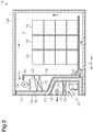
- Fig. 2 shows the structure of the wall 12 of the first container 1A as an example.
- a lower portion of the wall 12 is bulged toward the interior of the first container 1A to form a concave portion 15.
- an exterior accommodation space S1 is defined at an exterior side of the lower portion of the wall 12
- an interior accommodation space S2 is defined at an interior side of the upper portion of the wall 12.
- the wall 12 includes a metal exterior casing 12a, a metal interior casing 12b, and a thermal insulation layer 12c sandwiched between the metal exterior casing 12a and the metal interior casing 12b.
- An example of the material of the exterior casing 12a and the interior casing 12b is aluminum.
- the thermal insulation layer 12c is formed of a foamed material.
- a partition plate 16 is disposed in an interior side of the casing 10A to separate the accommodation space S and the interior accommodation space S2 of the casing 10A.
- the partition plate 16 is spaced apart from the wall 12 in the first direction X.
- the exterior accommodation space S1 and the interior accommodation space S2 accommodate the refrigeration apparatus 20 including a refrigerant circuit 30. More specifically, the refrigeration apparatuses 20 includes, for example, a compressor 21, a condenser 22, an exterior fan 23, an interior fan 24, an evaporator 25, and an electric component 26 (refer to Fig. 1B ).
- the exterior accommodation space S1 accommodates the compressor 21, the condenser 22, the exterior fan 23, and the electric component 26.
- the interior accommodation space S2 accommodates the interior fan 24 and the evaporator 25.
- the refrigeration apparatus 20 including a refrigerant circuit 30 of the second container 1B and the refrigeration apparatus 20 including a refrigerant circuit 30 of the third container 1C have the same structure as the refrigeration apparatus 20 including the refrigerant circuit 30 of the first container 1A. In the description hereafter, the refrigeration apparatus 20 of the first container 1A will be described. The refrigeration apparatus 20 of the second container 1B and the refrigeration apparatus 20 of the third container 1C will not be described in detail.
- the refrigeration apparatus 20 includes the refrigerant circuit 30 in which, for example, the compressor 21, the condenser 22, and the evaporator 25 are connected by a refrigerant pipe.
- the refrigerant circuit 30 includes a main circuit 31, a hot gas bypass circuit 32, and a liquid refrigerant bypass circuit 41.
- the main circuit 31 is configured by sequentially connecting the compressor 21 that is driven by a motor, the condenser 22, a first expansion valve 27A, and the evaporator 25 in series with the refrigerant pipe.
- the exterior accommodation space accommodates, for example, the compressor 21, the condenser 22, the first expansion valve 27A, and the exterior fan 23, which circulates the air outside the storage to the condenser 22.
- the interior accommodation space accommodates, for example, the evaporator 25 and the interior fan 24, which circulates the air in the storage to the evaporator 25.
- the compressor 21 may be, for example, a rotary compressor or a scroll compressor.
- the compressor 21 is configured so that the operating capacity is variable when an inverter controls the operating frequency to control the rotational speed.
- the condenser 22 and the evaporator 25 may be a fin-and-tube heat exchanger.
- the condenser 22 exchanges heat between the air outside the storage supplied by the exterior fan 23 and the refrigerant circulating in the condenser 22.
- the evaporator 25 exchanges heat between the air in the storage supplied by the interior fan 24 and the refrigerant circulating in the evaporator 25.
- An example of the exterior fan 23 and the interior fan 24 is a propeller fan.
- a drain pan 38 is disposed below the evaporator 25. The drain pan 38 collects, for example, frost and ice blocks falling from the evaporator 25 and water condensed from the air.
- the first expansion valve 27A may be, for example, an electric expansion valve configured so that the opening degree is variable using a pulse motor.
- the compressor 21 and the condenser 22 are connected by a high pressure gas pipe 34 that includes a first opening-closing valve 28A and a check valve 29 sequentially arranged in a direction in which the refrigerant flows.
- the first opening-closing valve 28A may be, for example, an electric expansion valve configured so that the opening degree is variable using a pulse motor.
- the check valve 29 allows the refrigerant to flow in directions of arrows shown in Fig. 3 .
- the condenser 22 and the first expansion valve 27A are connected by a high pressure liquid pipe 35 that includes a receiver 39, a second opening-closing valve 29B, a dryer 40, and a supercooling heat exchanger 33 sequentially arranged in the direction in which the refrigerant flows.
- the second opening-closing valve 29B may be, for example, an electromagnetic valve configured to open and close.
- the supercooling heat exchanger 33 includes a primary passage 33a and a secondary passage 33b configured to exchange heat with each other.
- the primary passage 33a is disposed in the main circuit 31 between the dryer 40 and the first expansion valve 27A.
- the secondary passage 33b is disposed in the liquid refrigerant bypass circuit 41.
- the liquid refrigerant bypass circuit 41 is a bypass circuit that connects the high pressure liquid pipe 35 and an intermediate pressure portion (not shown) of a compression mechanism of the compressor 21.
- a third opening-closing valve 29C and a second expansion valve 27B are sequentially connected, in the direction in which the high pressure liquid refrigerant flows, to the liquid refrigerant bypass circuit 41 between the high pressure liquid pipe 35 and the secondary passage 33b.
- the second expansion valve 27B expands the liquid refrigerant to an intermediate pressure, so that the liquid refrigerant has a lower temperature than the liquid refrigerant flowing through the high pressure liquid pipe 35 and flows to the secondary passage 33b.
- the third opening-closing valve 29C may be, for example, an electromagnetic valve configured to open and close.
- the second expansion valve 27B may be, for example, an electric expansion valve configured so that the opening degree is variable using a pulse motor.
- the hot gas bypass circuit 32 connects a high pressure gas pipe 34 and the inlet side of the evaporator 25 to send the high-pressure high-temperature gas refrigerant discharged from the compressor 21 to the inlet side of the evaporator 25.
- the hot gas bypass circuit 32 includes a main passage 42, and a first branch passage 43 and a second branch passage 44 divided from the main passage 42.
- the first branch passage 43 and the second branch passage 44 configure a parallel circuit in which one end of each of the first branch passage 43 and the second branch passage 44 is connected to the main passage 42 and the other end is connected to the inlet side of the evaporator 25, that is, a low pressure connection pipe 36 that extends between the first expansion valve 27A and the evaporator 25.
- the main passage 42 includes a fourth opening-closing valve 29D.
- the fourth opening-closing valve 29D may be, for example, an electromagnetic valve configured to open and close.
- the first branch passage 43 includes only a pipe.
- the second branch passage 44 includes a drain pan heater 45.
- the drain pan heater 45 is disposed at the bottom of the drain pan 38 to heat the drain pan 38 with the refrigerant having a high temperature.
- the refrigeration apparatus 20 including the refrigerant circuit 30 is provided with various sensors.
- the refrigeration apparatus 20 includes an intake air temperature detector 46 and a blow-out air temperature detector 47.
- the intake air temperature detector 46 is disposed at the intake side of the evaporator 25 to detect the temperature of the air in the storage immediately before passing through the evaporator 25.
- the blow-out air temperature detector 47 is disposed at the blow-out side of the evaporator 25 to detect the temperature of the air in the storage immediately after passing through the evaporator 25.
- the first container 1A of the refrigeration system 1 includes a first controller 50
- the second container 1B includes a second controller 60
- the third container 1C includes a third controller 70.
- the first controller 50 receives a signal (hereafter, referred to as "intake air temperature Tv1”) corresponding to the temperature of the air in the storage immediately before passing through the evaporator 25.
- the signal is a detection result of the intake air temperature detector 46 of the refrigeration apparatus 20 of the first container 1A.
- the first controller 50 also receives a signal (hereafter, referred to as "blow-out air temperature Tb1”) corresponding to the temperature of the air in the storage immediately after passing through the evaporator 25.
- the signal is a detection result of the blow-out air temperature detector 47 of the refrigeration apparatus 20 of the first container 1A.
- the second controller 60 receives a signal (hereafter, referred to as "intake air temperature Tv2") corresponding to the temperature of the air in the storage immediately before passing through the evaporator 25.
- the signal is a detection result of the intake air temperature detector 46 of the refrigeration apparatus 20 of the second container 1B.
- the second controller 60 also receives a signal (hereafter, referred to as "blow-out air temperature Tb2”) corresponding to the temperature of the air in the storage immediately after passing through the evaporator 25.
- the signal is a detection result of the blow-out air temperature detector 47 of the refrigeration apparatus 20 of the second container 1B.
- the third controller 70 receives a signal (hereafter, referred to as "intake air temperature Tv3”) corresponding to the temperature of the air in the storage immediately before passing through the evaporator 25.
- the signal is a detection result of the intake air temperature detector 46 of the refrigeration apparatus 20 of the third container 1C.
- the third controller 70 also receives a signal (hereafter, referred to as "blow-out air temperature Tb3") corresponding to the temperature of the air in the storage immediately after passing through the evaporator 25.
- the signal is a detection result of the blow-out air temperature detector 47 of the refrigeration apparatus 20 of the third container 1C.
- the first controller 50, the second controller 60, and the third controller 70 have the same configuration.
- the first controller 50 includes a first control unit 51, which is an example of a control unit, a first communication unit 52, which is an example of a communication unit, a first operating unit 53, which is an example of an operating unit, and a clock 54.
- the first control unit 51 includes, for example, an arithmetic processing unit that executes a predetermined control program and a storage unit.
- the arithmetic processing unit includes, for example, a central processing unit (CPU) or a micro processing unit (MPU).
- the storage unit stores various control programs and information used for various control processes.
- the storage unit includes, for example, a nonvolatile memory and a volatile memory.
- the first communication unit 52 includes a transmitter 52a and a receiver 52b.
- the first communication unit 52 is electrically connected to the first control unit 51, the first operating unit 53, and the clock 54.
- the first communication unit 52 communicates with the second controller 60 and the third controller 70.
- the first operating unit 53 includes a touch screen or the like. When operated by an operator, the first operating unit 53 sends operating information such as a change in various settings to the first control unit 51.
- the clock 54 may be, for example, an analog quartz clock.
- the second controller 60 includes a second control unit 61, which is an example of a control unit, a second communication unit 62, which is an example of a communication unit, a second operating unit 63, which is an example of an operating unit, and a clock 64.
- the second communication unit 62 includes a transmitter 62a and a receiver 62b.
- the third controller 70 includes a third control unit 71, which is an example of a control unit, a third communication unit 72, which is an example of a communication unit, a third operating unit 73, which is an example of an operating unit, and a clock 74.
- the third communication unit 72 includes a transmitter 72a and a receiver 72b.
- the first communication unit 52, the second communication unit 62, and the third communication unit 72 are configured so that the refrigeration apparatuses 20 of the containers 1A to 1C connect and communicate with each other. More specifically, the first communication unit 52, the second communication unit 62, and the third communication unit 72 are connected so as to perform communication with each other. In the present embodiment, the first communication unit 52, the second communication unit 62, and the third communication unit 72 are connected by a communication line 80. More specifically, the communication line 80 is connected to a communication port 55 of the first controller 50, a communication port 65 of the second controller 60, and a communication port 75 of the third controller 70. The communication port 55 of the first controller 50 is electrically connected to the first communication unit 52. The communication port 65 of the second controller 60 is electrically connected to the second communication unit 62. The communication port 75 of the third controller 70 is electrically connected to the third communication unit 72.
- the control units 51, 61, and 71 control operations of the containers 1A to 1C such as a refrigerating-cooling operation and a defrosting operation.
- the refrigerating-cooling operation and the defrosting operation will now be described with reference to Fig. 3 .
- the first opening-closing valve 28A, a second opening-closing valve 28B, and a third opening-closing valve 28C are open, and a fourth opening-closing valve 28D is closed.
- the opening degrees of the first expansion valve 27A and the second expansion valve 27B are appropriately adjusted.
- the compressor 21, the exterior fan 23, and the interior fan 24 are operated.
- the refrigerant circulates as indicated by the solid arrows. More specifically, the gas refrigerant is compressed in the compressor 21 and is condensed in the condenser 22 to become the liquid refrigerant. Subsequently, the liquid refrigerant is stored in the receiver 39. The liquid refrigerant flows from the receiver 39 through the second opening-closing valve 28B and the dryer 40. The liquid refrigerant is supercooled in the primary passage 33a of the supercooling heat exchanger 33 and flows to the first expansion valve 27A.
- a portion of the liquid refrigerant discharged from the receiver 39 flows as a supercooling source through the third opening-closing valve 28C and the second expansion valve 27B to become a low-pressure low-temperature refrigerant.
- the low-pressure low-temperature refrigerant flows to the secondary passage 33b of the supercooling heat exchanger 33 to supercool the liquid refrigerant in the primary passage 33a.
- the liquid refrigerant supercooled in the supercooling heat exchanger 33 is depressurized in the first expansion valve 27A and then flows through the evaporator 25.
- the refrigerant absorbs heat from the air in the storage and evaporates. As a result, the air in the storage is cooled.
- the refrigerant evaporated in the evaporator 25 is drawn and compressed again in the compressor 21.
- frost collects on surfaces of, for example, a fin and a heat transfer tube of the evaporator 25.
- the frost gradually develops and enlarges.
- the controllers 50, 60, and 70 perform the defrosting operation, that is, an operation for removing frost from the evaporators 25.
- the defrosting operation directly supplies a high-temperature high-pressure gas refrigerant, which is compressed in the compressor 21, to the evaporator 25 bypassing the condenser 22, the receiver 39, the supercooling heat exchanger 33, and the first expansion valve 27A.
- the fourth opening-closing valve 28D is open, and the first opening-closing valve 28A, the second opening-closing valve 28B, the third opening-closing valve 28C, and the second expansion valve 27B are fully closed.
- the compressor 21 starts to operate, and the exterior fan 23 and the interior fan 24 are stopped.
- the high-pressure gas refrigerant compressed in the compressor 21 flows through the main passage 42 and the fourth opening-closing valve 28D and then divides into the first branch passage 43 and the second branch passage 44.
- the refrigerant divided into the second branch passage 44 flows through the drain pan heater 45.
- the refrigerant discharged from the drain pan heater 45 joins the refrigerant that has passed through the first branch passage 43 and flows through the evaporator 25.
- a high-pressure gas refrigerant (so-called hot gas) flows in the heat transfer tube.
- the frost collected on the fin and the heat transfer tube is gradually heated from an inner side by the refrigerant.
- the drain pan 38 gradually receives the frost from the evaporator 25.
- the refrigerant used to defrost the evaporator 25 is drawn and compressed again in the compressor 21.
- an ice block falls from the surface of the evaporator 25 and is received in the drain pan 38.
- the ice block is heated and melted by the refrigerant flowing in the drain pan heater 45.
- the melted water is discharged out of the storage through a predetermined flow passage.
- the containers 1A to 1C define the accommodation space S, and the refrigerating-cooling operation and the defrosting operation are performed in the accommodation space S.
- the controllers 50, 60, and 70 of the containers 1A to 1C start the defrosting operation. Since the times of the clocks 54, 64, and 74 of the controllers 50, 60, and 70 are set by an operator, the operator may set the clocks 54, 64, and 74 to different times.
- the times of the clocks 54, 64, and 74 may differ from each other as time elapses.
- the rest of the containers 1A to 1C do not start the defrosting operation, that is, continue the refrigerating-cooling operation.
- This refrigerating-cooling operation may hinder completion of defrosting of the one or more of the containers 1A to 1C and termination of the defrosting operation.
- the temperature of the accommodation space S will increase.
- the accommodation space S may be locally overcooled.
- the refrigeration system 1 of the present embodiment executes synchronized control that synchronously operates the refrigeration apparatuses 20 of the containers 1A to 1C.
- the refrigeration system 1 synchronizes timing at which the refrigeration apparatuses 20 of the containers 1A to 1C start the defrosting operation.
- the refrigeration system 1 synchronizes timing at which the refrigeration apparatuses 20 of the containers 1A to 1C end the defrosting operation. More preferably, in synchronized control, after the refrigeration apparatuses 20 of the containers 1Ato 1C end the defrosting operation, the refrigeration system 1 synchronizes the start timing of the refrigerating-cooling operation.
- the controllers 50, 60, and 70 of the containers 1A to 1C set one of the controllers 50, 60, and 70 to a master device and set the remaining two controllers to slave devices.
- the first control unit 51 of the first controller 50 is set to a main control unit
- the second control unit 61 of the second controller 60 and the third control unit 71 of the third controller 70 are set to slave control units.
- the first communication unit 52 transmits time information of the clock 54 of the first controller 50 to the second communication unit 62 and the third communication unit 72.
- the containers 1A to 1C synchronously start each of the defrosting operation and the refrigerating-cooling operation based on the time of the clock of the master device.
- the first control unit 51 executes the synchronized control.
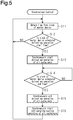
- the procedures of the synchronized control will now be described with reference to the flowchart shown in Fig. 5 .
- the first control unit 51 executes the synchronized control in a period from when the refrigeration apparatuses 20 of the containers 1A to 1C start to operate to when the refrigeration apparatuses 20 of the containers 1A to 1C stops operating.
- step S11 the first control unit 51 obtains the time of the clock 54 of the master device (first controller 50).
- step S12 the first control unit 51 determines whether the time of the clock 54 of the master device is a scheduled start time of the defrosting operation.
- the scheduled start time of the defrosting operation is set to, for example, a time after a predetermined time elapses from when the containers 1A to 1C start the refrigerating-cooling operation.
- the scheduled start time of the defrosting operation may be set to multiple times. In this case, an interval from a scheduled start time of the defrosting operation to the next scheduled start time of the defrosting operation is set to be greater than a period in which the defrosting operation is executed.
- step S12 When determining that the time of the clock 54 of the master device is not the scheduled start time of the defrosting operation (step S12: NO), the first control unit 51 proceeds to step S11. When determining that the time of the clock 54 of the master device is the scheduled start time of the defrosting operation (step S12: YES), the first control unit 51 proceeds to step S13 and synchronizes all of the containers 1A to 1C to start the defrosting operation. More specifically, the first control unit 51 transmits a defrosting start synchronization signal to the second control unit 61 and the third control unit 71 through the first communication unit 52 and starts the defrosting operation of the first container 1A.
- the defrosting start synchronization signal is an instruction signal for synchronously starting the defrosting operations of all of the containers 1A to 1C.
- the second control unit 61 starts the defrosting operation of the second container 1B.
- the third control unit 71 starts the defrosting operation of the third container 1C.
- step S14 the first control unit 51 determines whether the time of the clock 54 of the master device is a scheduled end time of the defrosting operation.
- the scheduled end time of the defrosting operation is set to a time after a predetermined time elapses from the scheduled start time of the defrosting operation.
- multiple scheduled start times of the defrosting operation are set, multiple scheduled end times of the defrosting operation are set in correspondence with the scheduled start times.
- step S14 NO
- the first control unit 51 When determining that the time of the clock 54 of the master device is not the scheduled end time of the defrosting operation (step S14: NO), the first control unit 51 returns to the determination of step S14. That is, when all of the containers 1A to 1C start the defrosting operations, the defrosting operations of all of the containers 1A to 1C continue until the scheduled end time of the defrosting operation.
- the first control unit 51 When determining that the time of the clock 54 of the master device is the scheduled end time of the defrosting operation (step S14: YES), the first control unit 51 proceeds to step S15 to synchronously end the defrosting operations of all of the containers 1A to 1C. More specifically, the first control unit 51 transmits a defrosting end synchronization signal to the second control unit 61 and the third control unit 71 through the first communication unit 52 and ends the defrosting operation of the first container 1A.
- the defrosting end synchronization signal is an instruction signal for synchronously ending the defrosting operations of all of the containers 1A to 1C.
- the second control unit 61 ends the defrosting operation of the second container 1B.
- the third control unit 71 ends the defrosting operation of the third container 1C.
- step S16 the first control unit 51 synchronously starts the refrigerating-cooling operations of all of the containers 1A to 1C. More specifically, the first control unit 51 transmits a refrigerating-cooling start synchronization signal to the second control unit 61 and the third control unit 71 through the first communication unit 52 and starts the refrigerating-cooling operation of the first container 1A.
- the refrigerating-cooling start synchronization signal is an instruction signal for synchronously resuming the refrigerating-cooling operations of all of the containers 1A to 1C.
- the second control unit 61 When receiving the refrigerating-cooling start synchronization signal from the first control unit 51 through the second communication unit 62, the second control unit 61 starts the refrigerating-cooling operation of the second container 1B.
- the third control unit 71 When receiving the refrigerating-cooling start synchronization signal from the first control unit 51 through the third communication unit 72, the third control unit 71 starts the refrigerating-cooling operation of the third container 1C. Then, the process returns to step S11.
- the master device first controller 50
- the slave devices second controller 60 and third controller 70
- the master device may not be able to instruct the slave devices to start the defrosting operation or synchronize the refrigerating-cooling operations. This may result in a failure of execution of the synchronized control.
- the master device may not be able to instruct the slave devices to start the defrosting operation or synchronize the refrigerating-cooling operations. This may result in a failure of execution of the synchronized control.
- the refrigeration system 1 of the present embodiment executes setting change control that sets one of the slave devices (second controller 60 and third controller 70) to a new master device and sets the master device (the first controller 50) to a slave device.
- the setting change control for example, as shown in the lower part of Fig. 6
- the second control unit 61 transmits the defrosting start synchronization signal, the defrosting end synchronization instruction, and the refrigerating-cooling start synchronization signal to the first control unit 51 and the third control unit 71.
- step S21 the second control unit 61 transmits a response check signal to the first control unit 51.
- step S22 the second control unit 61 determines whether a response signal is received from the first control unit 51.
- step S22 determines whether a response signal is received from the first control unit 51.
- step S23 determines whether a predetermined time has elapsed from when the response check signal is transmitted. The predetermined time is used to determine occurrence of an abnormality in transmission of a signal from the first control unit 51 and is set in advance through tests or the like.
- the second control unit 61 proceeds to step S24 and sets the second controller 60 to the master device and sets the first controller 50 to a slave device.
- the second control unit 61 is set to the main control unit, and the first control unit 51 is set to a slave control unit.
- the second control unit 61 executes synchronized control. In this case, the second control unit 61 operates the first controller 50 based on information (operating information) related to the operation of the first container 1A obtained before the first controller 50 malfunctions as the master device.
- the second control unit 61 transmits operating information of the first container 1A obtained before the first controller 50 malfunctions as the master device, that is, the operating information of the first container 1A lastly received from the first controller 50, to the first controller 50.
- the first control unit 51 operates the refrigeration apparatus 20 of the first container 1A based on the operating information of the first container 1A received from the second control unit 61.
- step S23 NO
- step S22 YES
- step S21 the second control unit 61 proceeds to step S21.
- the one or more of the containers 1A to 1C may fail to perform various operations. This may result in a failure of execution of the synchronized control.
- the second control unit 61 cannot obtain the blow-out air temperature Tb2 and thus may fail to start or end various operations of the second container 1B.
- the containers 1A to 1C transmit operating information or the like to each other through the communication units 52, 62, and 72.
- the first control unit 51 receives information related to the operation performed by the second control unit 61 and information related to the operation performed by the third control unit 71.
- the second control unit 61 receives information related to the operation performed by the first control unit 51 and information related to the operation performed by the third control unit 71.
- the third control unit 71 receives information related to the operation performed by the first control unit 51 and information related to the operation performed by the second control unit 61.
- the storage units of the control units 51, 61, and 71 store the information related to the operation performed by the first control unit 51, the information related to the operation performed by the second control unit 61, and the information related to the operation performed by the third control unit 71.
- Information related to operations performed by the control units 51, 61, and 71 includes the intake air temperatures Tv1 to Tv3, the blow-out air temperatures Tb1 to Tb3, the kind of operation performed by the control units 51, 61, and 71 (refrigerating-cooling operation and defrosting operation), operating frequencies of the compressors 21, rotational speeds of the exterior fans 23, rotational speeds of the interior fans 24, opening degrees of the expansion valves 27A and 27B, and opening degrees of the opening-closing valves 28A to 28D.
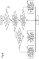
- the operation of the one or more of the containers 1A to 1C is controlled based on detection results of the intake air temperature detector 46 and the blow-out air temperature detector 47 of a remaining one of the containers 1A to 1C. For example, as shown in the lower part of Fig.
- the first control unit 51 determines whether at least one of the intake air temperature detector 46 or the blow-out air temperature detector 47 of the first container 1A is faulty. More specifically, the first control unit 51 determines whether the intake air temperature detector 46 and the blow-out air temperature detector 47 of the first container 1A have each transmitted a detection signal to the first controller 50 in a predetermined period. When the detection signal has not been received from at least one of the intake air temperature detector 46 or the blow-out air temperature detector 47 in the predetermined period, the first control unit 51 determines that at least one of the intake air temperature detector 46 or the blow-out air temperature detector 47 is faulty.
- step S31 When determining that neither the intake air temperature detector 46 nor the blow-out air temperature detector 47 of the first container 1A is faulty (step S31: NO), the first control unit 51 proceeds to step S32 and determines whether at least one of the intake air temperature detector 46 or the blow-out air temperature detector 47 of the second container 1B is faulty. More specifically, the second control unit 61 determines whether the intake air temperature detector 46 and the blow-out air temperature detector 47 of the second container 1B have each transmitted a detection signal to the second controller 60 in a predetermined period. This determination process is executed in the same manner as step S31. The second control unit 61 transmits the determination result to the first control unit 51.
- step S32 When determining that neither the intake air temperature detector 46 nor the blow-out air temperature detector 47 of the second container 1B is faulty (step S32: NO), the first control unit 51 proceeds to step S33 and determines whether at least one of the intake air temperature detector 46 or the blow-out air temperature detector 47 of the third container 1C is faulty. More specifically, the third control unit 71 determines whether the intake air temperature detector 46 and the blow-out air temperature detector 47 of the third container 1C have each transmitted a detection signal to the third controller 70 in a predetermined period. This determination process is executed in the same manner as step S31. The third control unit 71 transmits the determination result to the first control unit 51.
- step S33: NO When determining that neither the intake air temperature detector 46 nor the blow-out air temperature detector 47 of the third container 1C is faulty (step S33: NO), that is, when none of the intake air temperature detectors 46 and the blow-out air temperature detectors 47 of the containers 1A to 1C is faulty, the first control unit 51 temporarily ends the process.
- step S32 When determining that at least one of the intake air temperature detector 46 or the blow-out air temperature detector 47 of the second container 1B is faulty (step S32: YES), the first control unit 51 proceeds to step S34 and determines whether at least one of the intake air temperature detector 46 or the blow-out air temperature detector 47 of the third container 1C is faulty. When determining that at least one of the intake air temperature detector 46 or the blow-out air temperature detector 47 of the third container 1C is faulty (step S34: YES), the first control unit 51 proceeds to step S41.
- step S34 when an affirmative determination is made in step S34, the intake air temperature detector 46 and the blow-out air temperature detector 47 of the first container 1A are not faulty, and at least one of the intake air temperature detector 46 or the blow-out air temperature detector 47 of each of the second and third containers 1B and 1C is faulty. Therefore, in step S41, the first control unit 51 performs various operations of the second container 1B and the third container 1C based on the detection results of the intake air temperature detector 46 and the blow-out air temperature detector 47 of the first container 1A. When determining that neither the intake air temperature detector 46 nor the blow-out air temperature detector 47 of the third container 1C is faulty (step S34: NO), the first control unit 51 proceeds to step S42.
- step S34 when a negative determination is made in step S34, neither the intake air temperature detectors 46 nor the blow-out air temperature detectors 47 of the first container 1A and the third container 1C are faulty, at least one of the intake air temperature detector 46 or the blow-out air temperature detector 47 of the second container 1B is faulty. Therefore, in step S42, the first control unit 51 performs various operations of the second container 1B based on the detection results of the intake air temperature detector 46 and the blow-out air temperature detector 47 of the first container 1A. In step S42, the first control unit 51 may perform various operations of the second container 1B based on the detection results of the intake air temperature detector 46 and the blow-out air temperature detector 47 of the third container 1C.
- step S33 When determining in step S33 that at least one of the intake air temperature detector 46 or the blow-out air temperature detector 47 of the third container 1C is faulty (step S33: YES), the first control unit 51 proceeds to step S43. More specifically, when a negative determination is made in step S33, neither the intake air temperature detectors 46 nor the blow-out air temperature detectors 47 of the first container 1A and the second container 1B are faulty, and at least one of the intake air temperature detector 46 or the blow-out air temperature detector 47 of the third container 1C is faulty. Therefore, in step S43, the first control unit 51 controls various operations of the third container 1C based on the detection results of the intake air temperature detector 46 and the blow-out air temperature detector 47 of the second container 1B.
- step S31 when an affirmative determination is made in step S31, the first control unit 51 proceeds to step S35 and determines whether at least one of the intake air temperature detector 46 or the blow-out air temperature detector 47 of the second container 1B is faulty.
- step S35 determines whether at least one of the intake air temperature detector 46 or the blow-out air temperature detector 47 of the second container 1B is faulty.
- step S36 determines whether at least one of the intake air temperature detector 46 or the blow-out air temperature detector 47 of the third container 1C is faulty.
- step S35 When determining that at least one of the intake air temperature detector 46 or the blow-out air temperature detector 47 of the third container 1C is faulty (step S35: YES), the first control unit 51 proceeds to step S44. More specifically, when an affirmative determination is made in step S35, at least one of the intake air temperature detector 46 or the blow-out air temperature detector 47 of each of the containers 1A to 1C is faulty. In step S44, the first control unit 51 stops the operations of the containers 1A to 1C. In this case, the first control unit 51 may transmit a message indicating that the operations of the containers 1A to 1C are abnormal and have been stopped to, for example, a service center (control center) through the first communication unit 52.
- a service center control center
- step S36 When determining that neither the intake air temperature detector 46 nor the blow-out air temperature detector 47 of the third container 1C is faulty (step S36: NO), the first control unit 51 proceeds to step S45. More specifically, when a negative determination is made in step S36, at least one of the intake air temperature detector 46 or the blow-out air temperature detector 47 of each of the first and second containers 1A and 1B is faulty, and neither the intake air temperature detector 46 nor the blow-out air temperature detector 47 of the third container 1C is faulty. Therefore, in step S45, the first control unit 51 controls various operations of the first and second containers 1A and 1B based on the detection results of the intake air temperature detector 46 and the blow-out air temperature detector 47 of the third container 1C.
- step S45 When determining in step S45 that neither the intake air temperature detector 46 nor the blow-out air temperature detector 47 of the second container 1B is faulty (step S35: NO), the first control unit 51 proceeds to step S37 and determines whether at least one of the intake air temperature detector 46 or the blow-out air temperature detector 47 of the third container 1C is faulty. When determining that at least one of the intake air temperature detector 46 or the blow-out air temperature detector 47 of the third container 1C is faulty (step S37: YES), the first control unit 51 proceeds to step S46.
- step S37 when an affirmative determination is made in step S37, at least one of the intake air temperature detector 46 or the blow-out air temperature detector 47 of each of the first and third containers 1A and 1C is faulty, and neither the intake air temperature detector 46 nor the blow-out air temperature detector 47 of the second container 1B is faulty. Therefore, in step S46, the first control unit 51 controls various operations of the first and third containers 1A and 1C based on the detection results of the intake air temperature detector 46 and the blow-out air temperature detector 47 of the second container 1B.
- step S37 When determining that neither the intake air temperature detector 46 nor the blow-out air temperature detector 47 of the third container 1C is faulty (step S37: NO), the first control unit 51 proceeds to step S47. More specifically, when a negative determination is made in step S37, at least one of the intake air temperature detector 46 or the blow-out air temperature detector 47 of the first container 1A is faulty, and neither the intake air temperature detector 46 nor the blow-out air temperature detector 47 of the second and third containers 1B and 1C is faulty. Therefore, in step S47, the first control unit 51 controls various operations of the first container 1A based on the detection results of the intake air temperature detector 46 and the blow-out air temperature detector 47 of the second container 1B.
- the refrigeration apparatuses 20 of the containers 1A to 1C perform synchronized operation at a point in time of starting the refrigerating-cooling operation and change from the synchronized operation to separated operation after starting the refrigerating-cooling operation.
- the refrigeration apparatuses 20 of the containers 1A to 1C separately perform the refrigerating-cooling operation on at separate storage set temperatures. More specifically, in the separated operation, the refrigeration apparatuses 20 of the containers 1A to 1C separately control, for example, the compressor 21, the interior fan 24, and the exterior fan 23 in accordance with the difference between the storage set temperature and the storage temperature of the corresponding container.
- the refrigeration apparatus 20 of the first container 1A calculates the storage temperature based on, for example, the intake air temperature Tv1.
- the refrigeration apparatus 20 of the second container 1B calculates the storage temperature based on, for example, the intake air temperature Tv2.
- the refrigeration apparatus 20 of the third container 1C calculates the storage temperature based on, for example, the intake air temperature Tv3.
- the first control unit 51 transmits an instruction signal for starting the separated operation to the second control unit 61 and the third control unit 71 through the first communication unit 52.
- the second control unit 61 starts the separated operation of the second container 1B.
- the third control unit 71 starts the separated operation of the third container 1C.
- the separated control which separately operates the refrigeration apparatuses 20 of the containers 1Ato 1C, may be executed without execution of the synchronized control.
- the first control unit 51 performs the defrosting operation of the first container 1A.
- the second control unit 61 performs the defrosting operation of the second container 1B.
- the third control unit 71 performs the defrosting operation of the third container 1C.
- the control units 51, 61, and 71 separately control the containers 1A to 1C.
- the control units 51, 61, and 71 separately control the containers 1A to 1C.
- the rest of the containers 1A to 1C do not start the defrosting operation based on the start of the defrosting operation of the one or more of the containers 1A to 1C.
- the operator may select the separated control and the synchronized control by operating the operating units 53, 63, and 73.
- a first setting and a second setting may be selected.
- an operation performed on one of the operating units 53, 63, and 73 reflects operations of the remaining two operating units.
- an operation performed on one of the operating units 53, 63, and 73 does not reflect operations of the remaining two operating units.
- the first communication unit 52 transmits information indicating that synchronized control is selected to the second controller 60 and the third controller 70.
- the second controller 60 sets the second container 1B so that the second container 1B is controlled synchronously with the first container 1A and the third container 1C.
- the third controller 70 sets the third container 1C so that the third container 1C is controlled synchronously with the first container 1A and the second container 1B.
- the operating units 53, 63, and 73 are in the second setting, the operator operates each of the operating units 53, 63, and 73 to select, for example, the synchronized control. Accordingly, the controllers 50, 60, and 70 execute the synchronized control.
- the operator may set the containers 1A to 1C to a container that is subject to the synchronized control.
- the operator may select a container that undergoes the synchronized control and a container that undergoes the separated control, for example, in accordance with the kind of load in the containers 1A to 1C.
- the synchronized control may be executed on the first container 1A and the second container 1B, and the separated control may be executed on the third container 1C.
- the operator may set one of the controllers 50, 60, and 70 to the master device by operating the operating units 53, 63, and 73.
- controllers other than the controller that is set to the master device are automatically set to the slave devices. More specifically, for example, when the operator operates the first operating unit 53 to set the first controller 50 to the master device, the first communication unit 52 transmits information indicating that the first controller 50 is the master device to the second controller 60 and the third controller 70.
- the second controller 60 sets the second controller 60 to a slave device.
- the third controller 70 sets the third controller 70 to a slave device.
- the controllers 50, 60, and 70 send time information of the clock 54 of the master device and information related to operations of the containers 1A to 1C to each other. For example, when the clock 54 has reached a preset time (scheduled start time of defrosting operation) and the clocks 64 and 74 have not reached the scheduled start time, the first control unit 51 sends information indicating that the clock 54 has reached the scheduled start time to the second control unit 61 and the third control unit 71 through the first communication unit 52. The first control unit 51 transmits the defrosting start synchronization signal to the second control unit 61 and the third control unit 71 based on the information indicating that the clock 54 has reached the scheduled start time.
- a preset time scheduled start time of defrosting operation
- the defrosting operations of the containers 1Ato 1C synchronously start, thereby limiting separation between starts of the defrosting operations that would be caused by differences in the set time between the clocks 54, 64, and 74.
- the present embodiment has the following advantages.
- FIG. 11 A second embodiment of a refrigeration system 1 will now be described with reference to Fig. 11 .
- the refrigeration system 1 of the present embodiment differs from the refrigeration system 1 of the first embodiment in synchronized control.
- the same reference numerals are given to those elements that are the same as the corresponding elements of the refrigeration system 1 of the first embodiment. Such elements will not be described in detail.
- the containers 1A to 1C of the present embodiment perform the defrosting operation based on the amount of frost collected on the evaporator 25 and the difference (Tv1-Tb1, Tv2-Tb2, Tv3-Tb3) between the intake air temperature and the blow-out air temperature of the respective containers 1A to 1C. If the containers 1A to 1C are separately controlled, the amount of frost collected on the evaporator 25 varies between the containers 1A to 1C. This may produce a state in which one or more of the containers 1A to 1C perform the defrosting operation and the rest of the containers 1A to 1C perform the refrigerating-cooling operation.
- the refrigerating-cooling operation of the remaining containers 1A to 1C may overcool in the same manner as the first embodiment.
- the containers 1A to 1C are performing the defrosting operation, if one or more of the containers 1A to 1C end the defrosting operation and resume the refrigerating-cooling operation, the one or more of the containers 1A to 1C perform the refrigerating-cooling operation while the rest of the containers 1A to 1C perform the defrosting operation. This also may hinder termination of the defrosting operation and locally overcool a space where the refrigerating-cooling operation is performed.
- the refrigeration system 1 of the present embodiment executes the synchronized control, in which information related to the operations performed by the control units 51, 61, and 71 is obtained, when one of the containers 1A to 1C has started the defrosting operation, the remaining containers start the defrosting operation, and when one of the containers 1A to 1C has started the refrigerating-cooling operation, the remaining containers start the refrigerating-cooling operation.
- the first controller 50 is set to the master device
- the second controller 60 and the third controller 70 are set to the slave devices.
- the first control unit 51 used as the main control unit executes the synchronized control.
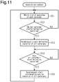
- the procedures of the synchronized control will now be described with reference to the flowchart shown in Fig. 11 .
- the first control unit 51 executes the synchronized control during a period from when the containers 1A to 1C start to operate to when the containers 1A to 1C stops operating.
- step S51 the first control unit 51 obtains the kind of operation of each of the containers 1A to 1C.
- step S52 the first control unit 51 determines whether any of the containers 1A to 1C has started the defrosting operation. More specifically, the first control unit 51, the second control unit 61, and the third control unit 71 send information indicating that the control units 51, 61, and 71 of the containers 1A to 1C have started the defrosting operation through the communication units 52, 62, and 72. More specifically, when the first container 1A has started the defrosting operation, the first control unit 51 transmits a defrosting operation start signal to the second control unit 61 and the third control unit 71.
- the second control unit 61 transmits a defrosting operation start signal to the first control unit 51 and the third control unit 71.
- the third control unit 71 transmits a defrosting operation start signal to the first control unit 51 and the second control unit 61.
- the first control unit 51 transmits the defrosting operation start signal
- the first control unit 51 determines that the first container 1A has started the defrosting operation.
- the defrosting operation start signal is received from the second control unit 61
- the first control unit 51 determines that the second container 1B has started the defrosting operation.
- the defrosting operation start signal is received from the third control unit 71
- the first control unit 51 determines that the third container 1C has started the defrosting operation.
- step S52 determines that any of the containers 1A to 1C has not started the defrosting operation (step S52: NO)
- step S52 proceeds to step S11.
- step S52: YES the first control unit 51 proceeds to step S53 and synchronizes all of the containers 1A to 1C to start the defrosting operation.
- the second control unit 61 starts the defrosting operation of the second container 1B when receiving the defrosting operation start signal from the first control unit 51
- the third control unit 71 starts the defrosting operation of the third container 1C when receiving the defrosting operation start signal from the first control unit 51.
- the first control unit 51 starts the defrosting operation of the first container 1A when receiving the defrosting operation start signal from the second control unit 61
- the third control unit 71 starts the defrosting operation of the third container 1C when receiving the defrosting operation start signal from the second control unit 61.
- the first control unit 51 starts the defrosting operation of the first container 1A when receiving the defrosting operation start signal from the third control unit 71
- the second control unit 61 starts the defrosting operation of the second container 1B when receiving the defrosting operation start signal from the third control unit 71.
- step S54 the first control unit 51 determines whether all of the containers 1A to 1C have ended the defrosting operations. More specifically, the first control unit 51, the second control unit 61, and the third control unit 71 send information indicating that the control units 51, 61, and 71 of the containers 1A to 1C have ended the defrosting operations through the communication units 52, 62, and 72. More specifically, when the first container 1A has end the defrosting operation, the first control unit 51 transmits a defrosting operation end signal to the second control unit 61 and the third control unit 71. When the second container 1B has ended the defrosting operation, the second control unit 61 transmits a defrosting operation end signal to the first control unit 51 and the third control unit 71.
- the third control unit 71 transmits a defrosting operation end signal to the first control unit 51 and the second control unit 61.
- the first control unit 51 transmits the defrosting operation end signal
- the first control unit 51 determines that the first container 1A has ended the defrosting operation.
- the first control unit 51 determines that the second container 1B has ended the defrosting operation when receiving the defrosting operation end signal from the second control unit 61, and determines that the third container 1C has ended the defrosting operation when receiving the defrosting operation end signal from the third control unit 71.
- step S54 NO
- the first control unit 51 again proceeds to the determination of step S54.
- the operation of the first container 1A is stopped, and the second container 1B and the third container 1C continue the defrosting operation.
- the second container 1B has ended the defrosting operation and the third container 1C has not ended the defrosting operation
- the operation of the first container 1A continues to be stopped, the operation of the second container 1B is stopped, and the third container 1C continues the defrosting operation.
- step S54 When determining that all of the containers 1A to 1C have ended the defrosting operations (step S54: YES), the first control unit 51 proceeds to step S55 and synchronizes all of the containers 1A to 1C to start the refrigerating-cooling operation. More specifically, the first control unit 51 transmits the refrigerating-cooling start synchronization signal to the second control unit 61 and the third control unit 71 through the first communication unit 52. Thus, the start of the refrigerating-cooling operation is synchronized between the containers 1A to 1C.
- the first control unit 51 performs the refrigerating-cooling operation of the first container 1A.
- the second control unit 61 performs the refrigerating-cooling operation of the second container 1B.
- the third control unit 71 performs the refrigerating-cooling operation of the third container 1C. Then, the process returns to step S51.
- the first control unit 51 transmits the defrosting operation start signal to the second control unit 61 and the third control unit 71.
- the second control unit 61 and the third control unit 71 start the defrosting operations of the second container 1B and the third container 1C based on the defrosting operation start signal.
- the second and third containers 1B and 1C start the defrosting operations in cooperation with the start of the defrosting operation of the first container 1A.
- the containers 1A to 1C synchronously start the defrosting operation. This reduces situations in which the defrosting operations of the containers 1Ato 1C separately start, causing some of the containers 1A to 1C to execute the refrigerating-cooling operation.
- the present embodiment has the same advantages as the first embodiment.
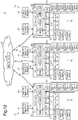
- a third embodiment of a refrigeration system 1 will now be described with reference to Fig. 12 .
- the refrigeration system 1 of the present embodiment differs from the refrigeration system 1 of the first embodiment in the communication mode of the controllers 50, 60, and 70.
- the same reference numerals are given to those elements that are the same as the corresponding elements of the refrigeration system 1 of the first embodiment. Such elements will not be described in detail.
- the first communication unit 52 of the first controller 50, the second communication unit 62 of the second controller 60, and the third communication unit 72 of the third controller 70 are configured to perform wireless communication with an external server 90.
- An example of the server 90 is a cloud server.
- the server 90 includes a main control unit 91.
- the main control unit 91 includes, for example, an arithmetic processing unit that executes a predetermined control program and a storage unit.
- the communication units 52, 62, and 72 transmit the times of the clocks 54, 64, and 74 and information related to operations performed by the control units 51, 61, and 71 to the main control unit 91.
- the main control unit 91 stores the times of the clocks 54, 64, and 74 and the information related to operations performed by the control units 51, 61, and 71.
- Information related to operations performed by the control units 51, 61, and 71 includes the intake air temperatures Tv1 to Tv3, the blow-out air temperatures Tb1 to Tb3, the kind of operation performed by the control units 51, 61, and 71 (refrigerating-cooling operation and defrosting operation), operating frequencies of the compressors 21, rotational speeds of the exterior fans 23, rotational speeds of the interior fans 24, opening degrees of the expansion valves 27A and 27B, and opening degrees of the opening-closing valves 28A to 28D.
- the main control unit 91 transmits control signals related to operations of the containers 1A to 1C to the communication units 52, 62, and 72 based on the times of the clocks 54, 64, and 74 and the information related to operations performed by the control units 51, 61, and 71.
- the control units 51, 61, and 71 control operations of the respective containers 1A to 1C based on the control signals of the main control unit 91. That is, the control units 51, 61, and 71 are slave control units of the main control unit 91.
- the main control unit 91 executes various controls such as the synchronized control and the substituted control on the containers 1A to 1C.
- the main control unit 91 transmits the defrosting start synchronization signal, the defrosting end synchronization signal, and the refrigerating-cooling start synchronization signal to the communication units 52, 62, and 72 in the same manner as in the synchronized control of the first embodiment.
- the communication units 52, 62, and 72 transmit the defrosting start synchronization signal, the defrosting end synchronization signal, and the refrigerating-cooling start synchronization signal to the control units 51, 61, and 71.
- the communication units 52, 62, and 72 transmit determination results indicating whether at least one of the intake air temperature detectors 46 or the blow-out air temperature detectors 47 of the containers 1A to 1C is faulty to the main control unit 91.
- the main control unit 91 controls the operations of the containers 1A to 1C based on the determination results received from the communication units 52, 62, and 72 in the same manner as in the substituted control of the first embodiment.
- the present embodiment has the following advantages.
- the communication units 52, 62, and 72 of the refrigeration apparatuses 20 of the containers 1A to 1C are configured to be connected to the server 90.
- the server 90 synchronization of the start of the refrigerating-cooling operation and synchronization of the start of the defrosting operation between the refrigeration apparatuses 20 are controlled through the main control unit 91 of the server 90, which may be a cloud-based server.
- the main control unit 91 of the server 90 which may be a cloud-based server.
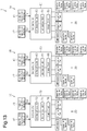
- a fourth embodiment of a refrigeration system 1 will now be described with reference to Fig. 13 .
- the refrigeration system 1 of the present embodiment differs in the configurations of the controllers 50, 60, and 70.
- the same reference numerals are given to those elements that are the same as the corresponding elements of the refrigeration system 1 of the first embodiment. Such elements will not be described in detail.
- the controllers 50, 60, and 70 of the present embodiment include atomic clocks 56, 66, and 76 instead of the clocks 54, 64, and 74.
- the time of the atomic clock 56 is transmitted to the first control unit 51.
- the time of the atomic clock 66 is transmitted to the second control unit 61.
- the time of the atomic clock 76 is transmitted to the third control unit 71.
- the control units 51, 61, and 71 of the present embodiment start the defrosting operation at a preset first start time (scheduled start time of defrosting operation) and end the defrosting operation at a preset first end time (scheduled end time of defrosting operation). More specifically, when determining that the atomic clock 56 has reached the scheduled start time of the defrosting operation, the first control unit 51 starts the defrosting operation. When determining that the atomic clock 56 has reached the scheduled end time of the defrosting operation, the first control unit 51 ends the defrosting operation. When determining that the atomic clock 66 has reached the scheduled start time of the defrosting operation, the second control unit 61 starts the defrosting operation.
- the second control unit 61 ends the defrosting operation.
- the third control unit 71 starts the defrosting operation.
- the third control unit 71 ends the defrosting operation.
- the control units 51, 61, and 71 of the present embodiment separately control the starting and ending of the defrosting operation.
- control units 51, 61, and 71 start the refrigerating-cooling operation at a preset second start time (scheduled start time of refrigerating-cooling operation) and end the refrigerating-cooling operation at a preset second end time (scheduled end time of refrigerating-cooling operation). More specifically, when determining that the atomic clock 56 has reached the scheduled start time of the refrigerating-cooling operation, the first control unit 51 performs the refrigerating-cooling operation. When determining that the atomic clock 56 has reached the scheduled end time of the refrigerating-cooling operation, the first control unit 51 ends the refrigerating-cooling operation.
- the second control unit 61 When determining that the atomic clock 66 has reached the scheduled start time of the refrigerating-cooling operation, the second control unit 61 performs the refrigerating-cooling operation. When determining that the atomic clock 66 has reached the scheduled end time of the refrigerating-cooling operation, the second control unit 61 ends the refrigerating-cooling operation. When determining that the atomic clock 76 has reached the scheduled start time of the refrigerating-cooling operation, the third control unit 71 performs the refrigerating-cooling operation. When determining that the atomic clock 76 has reached the scheduled end time of the refrigerating-cooling operation, the third control unit 71 ends the refrigerating-cooling operation.
- a defrosting period (period from the scheduled start time of the defrosting operation to the scheduled end time of the defrosting operation) and a refrigerating-cooling period (period from the scheduled start time of the refrigerating-cooling operation to the scheduled end time of the refrigerating-cooling operation) are set so that the defrosting period does not overlap with the refrigerating-cooling period.
- Each of the control units 51, 61, and 71 of the present embodiment may set the first start time to a time after a first predetermined time elapses from the second start time, which is the scheduled start time of the refrigerating-cooling operation.
- each of the control units 51, 61, and 71 may set the first end time, which is the scheduled end time of the defrosting operation, to a time after a second predetermined time elapses from the first start time, and may set a third start time, that is, a resuming time of the refrigerating-cooling operation, to a time after a third predetermined time elapses from the first end time.
- control units 51, 61, and 71 may use the atomic clocks 56, 66, and 76 to interrupt the refrigerating-cooling operation and perform the defrosting operation.
- multiple first start times and multiple first end times may be set so that the refrigerating-cooling operation is interrupted with the defrosting operation a number of times.
- the first predetermined time, the second predetermined time, and the third predetermined time may be set in any manner.
- the second predetermined time is shorter than the first predetermined time
- the third predetermined time is shorter than the second predetermined time.
- the third predetermined time may be set to zero seconds so that the refrigerating-cooling operation is resumed immediately after the defrosting operation ends.
- the present embodiment has the following advantages.
- the control units 51, 61, and 71 start the defrosting operation or the refrigerating-cooling operation based on the times of the atomic clocks 56, 66, and 76 mounted on the refrigeration apparatuses 20 of the containers 1A to 1C.
- information of the atomic clocks 56, 66, and 76 mounted on the refrigeration apparatuses 20 of the containers 1A to 1C is used to control start of the refrigerating-cooling operation and start of the defrosting operation of the refrigeration apparatuses 20.
- the refrigeration apparatuses 20 synchronously start the refrigerating-cooling operation, and the refrigeration apparatuses 20 synchronously start the defrosting operation.
- variations in the operation of the refrigeration apparatuses 20 are limited.
- the above embodiments exemplify, without any intention to limit, applicable forms of a refrigeration system according to the present disclosure.
- the refrigeration system is applicable to, for example, modified examples of the above embodiments that are described below and combinations of at least two of the modified examples that do not contradict each other.
- the same reference numerals are given to those elements that are the same as the corresponding elements of the above embodiments. Such elements will not be described in detail.
- the first communication unit 52 of the first controller 50, the second communication unit 62 of the second controller 60, and the third communication unit 72 of the third controller 70 may be configured to perform wireless communication with each other.
- the communication line 80 is omitted.
- the communication units 52, 62, and 72 that are configured to perform wireless communication with each other are, for example, a universal serial bus (USB) adapter configured to perform wireless communication such as a Wi-Fi (wireless LAN) slave device.
- the USB adapter is connected to each of the communication ports 55, 65, and 75.
- the first control unit 51 may transmit the defrosting start synchronization signal to the second control unit 61 and the third control unit 71 through the first communication unit 52.
- the first control unit 51 may transmit the defrosting start synchronization signal to the second control unit 61 and the third control unit 71 through the first communication unit 52.
- the first control unit 51 transmits the defrosting start synchronization signal, instead of the defrosting operation start signal, to the second control unit 61 and the third control unit 71 to synchronously start the defrosting operation of the containers 1A to 1C.
- the defrosting operation or the refrigerating-cooling operation may be started based on a clock (e.g., clock in the cloud) of the server 90.
- a clock e.g., clock in the cloud
- information of the clock of the server 90 is used to control start of the refrigerating-cooling operation and start of the defrosting operation of the refrigeration apparatuses 20.
- the refrigeration apparatuses 20 synchronously start the refrigerating-cooling operation, and the refrigeration apparatuses 20 synchronously start the defrosting operation.
- variations in the operation of the refrigeration apparatuses 20 are limited.
- the first communication unit 52 may be added to the first controller 50
- the second communication unit 62 may be added to the second controller 60
- the third communication unit 72 may be added to the third controller 70.
- the controllers 50, 60, and 70 may send information related to operations performed by the containers 1A to 1C to each other.
- the refrigeration system 1 may control the refrigeration apparatuses 20 of the containers 1A to 1C so that in the refrigeration apparatuses 20 of the containers 1A to 1C, a refrigeration apparatus 20 performing the defrosting operation coincides with a refrigeration apparatus 20 performing an operation other than the defrosting operation. More specifically, in the separated operation of the refrigeration system 1, one of the refrigeration apparatuses 20 performing the defrosting operation may coincide with one of the refrigeration apparatuses 20 performing an operation other than the defrosting operation (e.g., refrigerating-cooling operation).
- the refrigeration system 1 determines whether to perform the defrosting operation based on, for example, the amount of frost collected on the evaporators 25 and the differences (Tv1-Tb1, Tv2-Tb2, Tv3-Tb3) between the intake air temperature and the blow-out air temperature of the containers 1A to 1C.
- the refrigeration system 1 may decrease cooling power of the refrigeration apparatus 20 corresponding to a location where the storage temperature is relatively low and increase cooling power of the refrigeration apparatus 20 corresponding to a location where the storage temperature is relatively high.
- the refrigeration system 1 controls the refrigerating-cooling operation of the refrigeration apparatuses 20 of the containers 1A to 1C so that the storage temperatures of the containers 1A to 1C reach the medium one of the storage temperatures of the containers 1A to 1C.
- the refrigeration system 1 sets the storage set temperature to the storage temperature of the second container 1B.
- the refrigeration system 1 decreases cooling power of the refrigeration apparatus 20 of the first container 1A having the low storage temperature and increases cooling power of the refrigeration apparatus 20 of the third container 1C having the high storage temperature.
- the setting change control of each embodiment may synchronize the master device with the slave devices and control the master device having the mulfunction based on operating information of the slave devices. More specifically, when the first controller 50 used as the master device malfunctions as the master device, the second control unit 61 synchronizes with the first controller 50 and operates the first controller 50 based on information (operating information) related to the operation of the second container 1B. Instead of the second control unit 61, the third control unit 71 may synchronize with the first controller 50 and operate the first controller 50 based on information (operating information) related to the operation of the second container 1B.
- a case in which the master device malfunctions as the master device includes a case in which the clock 54 of the master device (first controller 50) is faulty.
- the clock 54 of the master device first controller 50
- one of the slave devices having a non-faulty clock is changed to the master device, and the master device (first controller 50) is changed to a slave device.
- the new master device executes synchronized control based on the non-faulty clock.
- the specific procedures are shown in the flowchart of the setting change control in Fig. 15 .
- the second control unit 61 determines whether the clock 54 of the master device is faulty. When determining that the clock 54 of the master device is not faulty (step S61: NO), the second control unit 61 temporarily ends the process.
- step S61 When determining that the clock 54 of the master device is faulty (step S61: YES), the second control unit 61 proceeds to step S62 and sets the second controller 60 to the master device and sets the first controller 50 to a slave device. In step S63, instead of the first control unit 51, the second control unit 61 executes the synchronized control. Synchronized control executed by the second control unit 61 is executed based on the clock 64 of the second controller 60.
- the setting change control of this modified example may be combined and executed with the setting change control of each embodiment.
- the container having the malfunctioning master device may be operated based on information of the operation of a container located adjacent to the container having the new master device.
- the container having the malfunctioning master device may control the operation based on the operating information of the container.
- the control unit of the container that is newly set to the master device transmits the defrosting start synchronization signal, the defrosting end synchronization signal, and the refrigerating-cooling start synchronization signal to the control unit of the container having the malfunctioning master device so that the containers 1A to 1C synchronize with each other.
- the operating units 53, 63, and 73 of the controllers 50, 60, and 70 may be configured to perform only one of the setting of the master device and the slave devices and the setting of the synchronized control, which synchronously operates the refrigeration apparatuses 20, and the separated control, which separately operates the refrigeration apparatuses 20.
- the operator may change the setting related to the containers 1A to 1C with a remote operation using an external device.
- the operator operates a tablet 100, which is an example of the external device, to change the setting related to the containers 1A to 1C.
- the tablet 100 is configured to communicate with the controllers 50, 60, and 70.
- the setting related to the containers 1A to 1C includes, for example, the selecting of the synchronized control and the separated control and the setting of the master device and the slave devices.
- a smartphone may be used instead of the tablet 100. More specifically, the operator may use an external device configured to communicate with the containers 1A to 1C to change the setting related to the containers 1A to 1C.
- the operator may operate an external device to manually perform the setting of the master device and the slave devices and the setting of control (synchronized control) that synchronously operates the refrigeration apparatuses 20 and control (separated control) that separately operates the refrigeration apparatuses 20.
- At least one of the containers 1A to 1C may be joined in the first direction X.
- the wall opposite to the wall 12, on which the refrigeration apparatus 20 is disposed, in the first direction X may be removed to form an opening in each container.
- the openings may be opposed to each other to join the containers.
- multiple containers including the refrigeration apparatuses 20 may be joined to a container that does not include the refrigeration apparatus 20 to form a stationary storage.
- the refrigeration system 1 has a configuration in which the first container 1A, the second container 1B, and the third container 1C are joined.
- the number of containers in the refrigeration system 1 is not limited to this and may be changed to any number that is greater than or equal to two.
- a refrigeration system may have a configuration in which four or more containers are joined.
- refrigeration system 1A) first container, 1B) second container, 1C) third container, 20) refrigeration apparatus, 46) intake air temperature detector, 47) blow-out air temperature detector, 51) first control unit (control unit, main control unit), 52) first communication unit (communication unit), 53) first control unit (control unit), 54) clock, 61) second control unit (control unit, slave control unit), 62) second communication unit (communication unit), 63) second operating unit (operating unit), 64) clock, 71) third control unit (control unit, slave control unit), 72) third communication unit (communication unit), 73) third operating unit (operating unit), 74) clock, 90) server, 91) main control unit, 100) tablet (external device)
Landscapes
- Engineering & Computer Science (AREA)
- Physics & Mathematics (AREA)
- Mechanical Engineering (AREA)
- Thermal Sciences (AREA)
- General Engineering & Computer Science (AREA)
- Chemical & Material Sciences (AREA)
- Combustion & Propulsion (AREA)
- Devices That Are Associated With Refrigeration Equipment (AREA)
- Defrosting Systems (AREA)
- Cold Air Circulating Systems And Constructional Details In Refrigerators (AREA)
Applications Claiming Priority (2)
| Application Number | Priority Date | Filing Date | Title |
|---|---|---|---|
| JP2017206316 | 2017-10-25 | ||
| PCT/JP2018/036408 WO2019082599A1 (ja) | 2017-10-25 | 2018-09-28 | 冷凍システム |
Publications (3)
| Publication Number | Publication Date |
|---|---|
| EP3702702A1 true EP3702702A1 (de) | 2020-09-02 |
| EP3702702A4 EP3702702A4 (de) | 2021-08-11 |
| EP3702702B1 EP3702702B1 (de) | 2025-04-16 |
Family
ID=66246456
Family Applications (1)
| Application Number | Title | Priority Date | Filing Date |
|---|---|---|---|
| EP18871691.4A Active EP3702702B1 (de) | 2017-10-25 | 2018-09-28 | Kühlsystem |
Country Status (6)
| Country | Link |
|---|---|
| US (1) | US11959674B2 (de) |
| EP (1) | EP3702702B1 (de) |
| JP (2) | JPWO2019082599A1 (de) |
| CN (1) | CN111263873A (de) |
| SG (1) | SG11202003610UA (de) |
| WO (1) | WO2019082599A1 (de) |
Families Citing this family (2)
| Publication number | Priority date | Publication date | Assignee | Title |
|---|---|---|---|---|
| US11137805B2 (en) * | 2019-06-14 | 2021-10-05 | Klinge Corporation | Dual redundant cooling system for a container |
| EP4303503A1 (de) * | 2022-07-05 | 2024-01-10 | Carrier Corporation | Mehrkammertransportkühlsystem |
Family Cites Families (24)
| Publication number | Priority date | Publication date | Assignee | Title |
|---|---|---|---|---|
| JPS62219111A (ja) | 1986-03-20 | 1987-09-26 | Fujitsu General Ltd | 空気調和機の湿度制御回路 |
| JPH024180U (de) | 1988-06-20 | 1990-01-11 | ||
| JP3066147B2 (ja) | 1991-10-24 | 2000-07-17 | 三洋電機株式会社 | ショーケースの除霜制御方法 |
| JP3609437B2 (ja) | 1993-04-28 | 2005-01-12 | 三洋電機株式会社 | 空気調和装置の除霜方法 |
| JP3677114B2 (ja) * | 1996-03-15 | 2005-07-27 | 福島工業株式会社 | ショーケースの霜取制御システム |
| JPH1123040A (ja) | 1997-07-02 | 1999-01-26 | Matsushita Electric Ind Co Ltd | 乾燥装置 |
| JP3895869B2 (ja) | 1998-05-21 | 2007-03-22 | 三洋電機株式会社 | ショーケースの連結制御システム |
| JP2001305255A (ja) | 2000-04-20 | 2001-10-31 | Canon Inc | 時刻管理システム |
| JP4159243B2 (ja) * | 2000-12-11 | 2008-10-01 | 三洋電機株式会社 | 冷却貯蔵庫 |
| JP2004293923A (ja) | 2003-03-27 | 2004-10-21 | Sanden Corp | 蓄冷装置 |
| JP4267984B2 (ja) | 2003-09-01 | 2009-05-27 | ホシザキ電機株式会社 | 冷却装置群の運転制御システム |
| JP2006194512A (ja) | 2005-01-13 | 2006-07-27 | Toyo Tire & Rubber Co Ltd | 冷却収納庫の断熱パーティション構造 |
| JP2008008558A (ja) | 2006-06-29 | 2008-01-17 | Toshiba Kyaria Kk | 冷凍装置 |
| JP2009139028A (ja) * | 2007-12-07 | 2009-06-25 | Sanyo Electric Co Ltd | 制御装置および制御装置の制御方法 |
| JP2011112270A (ja) | 2009-11-25 | 2011-06-09 | Daikin Industries Ltd | コンテナ用冷凍装置 |
| US20130014527A1 (en) * | 2011-07-12 | 2013-01-17 | A.P. Moller - Maersk A/S | Temperature control in a refrigerated transport container |
| JP5845737B2 (ja) | 2011-09-02 | 2016-01-20 | 株式会社リコー | 情報処理装置、情報処理システム、情報処理プログラム |
| CN102889010A (zh) | 2012-10-23 | 2013-01-23 | 扬州通利冷藏集装箱有限公司 | 冷藏集装箱组合冷库 |
| KR101323686B1 (ko) | 2013-03-22 | 2013-10-30 | 극동일렉콤주식회사 | 냉동컨테이너 제어겸용 모니터링 시스템 |
| CN203239002U (zh) * | 2013-05-15 | 2013-10-16 | 中集集团集装箱控股有限公司 | 组合集装箱式冷库 |
| JP5865875B2 (ja) | 2013-07-12 | 2016-02-17 | ダイキン工業株式会社 | 船舶の糧食庫用冷凍装置 |
| JP6016730B2 (ja) | 2013-08-13 | 2016-10-26 | 三菱電機株式会社 | デマンド制御装置およびデマンド制御方法 |
| JP6790706B2 (ja) | 2016-02-17 | 2020-11-25 | 住友電気工業株式会社 | 監視装置、収集装置、監視システムおよび監視方法 |
| JP2017161102A (ja) | 2016-03-07 | 2017-09-14 | ホシザキ株式会社 | 冷却貯蔵庫 |
-
2018
- 2018-09-28 JP JP2019550897A patent/JPWO2019082599A1/ja active Pending
- 2018-09-28 WO PCT/JP2018/036408 patent/WO2019082599A1/ja not_active Ceased
- 2018-09-28 CN CN201880068612.0A patent/CN111263873A/zh active Pending
- 2018-09-28 SG SG11202003610UA patent/SG11202003610UA/en unknown
- 2018-09-28 US US16/757,871 patent/US11959674B2/en active Active
- 2018-09-28 EP EP18871691.4A patent/EP3702702B1/de active Active
-
2021
- 2021-07-19 JP JP2021118755A patent/JP2021165633A/ja active Pending
Also Published As
| Publication number | Publication date |
|---|---|
| CN111263873A (zh) | 2020-06-09 |
| US20200340723A1 (en) | 2020-10-29 |
| EP3702702B1 (de) | 2025-04-16 |
| WO2019082599A1 (ja) | 2019-05-02 |
| SG11202003610UA (en) | 2020-05-28 |
| JP2021165633A (ja) | 2021-10-14 |
| JPWO2019082599A1 (ja) | 2020-11-12 |
| US11959674B2 (en) | 2024-04-16 |
| EP3702702A4 (de) | 2021-08-11 |
Similar Documents
| Publication | Publication Date | Title |
|---|---|---|
| CN111780362B (zh) | 一种空调器及其控制方法 | |
| US9739521B2 (en) | Air conditioning apparatus | |
| EP3190357B1 (de) | Klimaanlage | |
| EP3056837B1 (de) | Kühlvorrichtung mit wärmerückgewinnung | |
| EP3859249B1 (de) | Kältemittelleckbestimmungsvorrichtung, gefriervorrichtung mit dieser kältemittelleckbestimmungsvorrichtung und kältemittelleckbestimmungsverfahren | |
| JP6641376B2 (ja) | 異常検知システム、冷凍サイクル装置、及び異常検知方法 | |
| US12516851B2 (en) | Refrigeration cycle system | |
| EP3702702B1 (de) | Kühlsystem | |
| CN113865029A (zh) | 空调器 | |
| US12410956B2 (en) | Refrigeration cycle system | |
| JP6448775B2 (ja) | 空気調和装置 | |
| US10359209B2 (en) | Air conditioning apparatus | |
| EP3150941A1 (de) | Kühlvorrichtung | |
| EP4596998A1 (de) | Kältekreislaufvorrichtung | |
| EP3396276B1 (de) | Klimatisierungsvorrichtung | |
| JP2009186123A (ja) | 空気調和装置 | |
| CN114777381B (zh) | 组合冰箱及其控制方法 | |
| EP4257891B1 (de) | Kältekreislaufsystem | |
| JP6636193B2 (ja) | 異常検知システム、冷凍サイクル装置、及び異常検知方法 | |
| EP3943841A1 (de) | Klimatisierungssystem | |
| EP4067765A1 (de) | Klimatisierungssystem und verfahren zur steuerung davon | |
| CN119085027B (zh) | 空调 | |
| EP4343236B1 (de) | Kältekreislaufvorrichtung und kältemittelleckagebestimmungssystem | |
| JP6678785B2 (ja) | 異常検知システム、冷凍サイクル装置、及び異常検知方法 | |
| CN106091265A (zh) | 空调器的控制方法 |
Legal Events
| Date | Code | Title | Description |
|---|---|---|---|
| STAA | Information on the status of an ep patent application or granted ep patent |
Free format text: STATUS: THE INTERNATIONAL PUBLICATION HAS BEEN MADE |
|
| PUAI | Public reference made under article 153(3) epc to a published international application that has entered the european phase |
Free format text: ORIGINAL CODE: 0009012 |
|
| STAA | Information on the status of an ep patent application or granted ep patent |
Free format text: STATUS: REQUEST FOR EXAMINATION WAS MADE |
|
| 17P | Request for examination filed |
Effective date: 20200417 |
|
| AK | Designated contracting states |
Kind code of ref document: A1 Designated state(s): AL AT BE BG CH CY CZ DE DK EE ES FI FR GB GR HR HU IE IS IT LI LT LU LV MC MK MT NL NO PL PT RO RS SE SI SK SM TR |
|
| AX | Request for extension of the european patent |
Extension state: BA ME |
|
| DAV | Request for validation of the european patent (deleted) | ||
| DAX | Request for extension of the european patent (deleted) | ||
| A4 | Supplementary search report drawn up and despatched |
Effective date: 20210709 |
|
| RIC1 | Information provided on ipc code assigned before grant |
Ipc: F25D 13/00 20060101AFI20210705BHEP Ipc: F25B 47/02 20060101ALI20210705BHEP Ipc: F25D 21/06 20060101ALI20210705BHEP Ipc: F25D 21/00 20060101ALI20210705BHEP Ipc: F25D 29/00 20060101ALI20210705BHEP |
|
| RAP3 | Party data changed (applicant data changed or rights of an application transferred) |
Owner name: DAIKIN INDUSTRIES, LTD. |
|
| STAA | Information on the status of an ep patent application or granted ep patent |
Free format text: STATUS: EXAMINATION IS IN PROGRESS |
|
| 17Q | First examination report despatched |
Effective date: 20230320 |
|
| P01 | Opt-out of the competence of the unified patent court (upc) registered |
Effective date: 20230525 |
|
| GRAP | Despatch of communication of intention to grant a patent |
Free format text: ORIGINAL CODE: EPIDOSNIGR1 |
|
| STAA | Information on the status of an ep patent application or granted ep patent |
Free format text: STATUS: GRANT OF PATENT IS INTENDED |
|
| INTG | Intention to grant announced |
Effective date: 20241212 |
|
| GRAS | Grant fee paid |
Free format text: ORIGINAL CODE: EPIDOSNIGR3 |
|
| GRAA | (expected) grant |
Free format text: ORIGINAL CODE: 0009210 |
|
| STAA | Information on the status of an ep patent application or granted ep patent |
Free format text: STATUS: THE PATENT HAS BEEN GRANTED |
|
| AK | Designated contracting states |
Kind code of ref document: B1 Designated state(s): AL AT BE BG CH CY CZ DE DK EE ES FI FR GB GR HR HU IE IS IT LI LT LU LV MC MK MT NL NO PL PT RO RS SE SI SK SM TR |
|
| REG | Reference to a national code |
Ref country code: GB Ref legal event code: FG4D |
|
| REG | Reference to a national code |
Ref country code: CH Ref legal event code: EP Ref country code: DE Ref legal event code: R096 Ref document number: 602018081200 Country of ref document: DE |
|
| REG | Reference to a national code |
Ref country code: IE Ref legal event code: FG4D |
|
| REG | Reference to a national code |
Ref country code: NL Ref legal event code: MP Effective date: 20250416 |
|
| PG25 | Lapsed in a contracting state [announced via postgrant information from national office to epo] |
Ref country code: NL Free format text: LAPSE BECAUSE OF FAILURE TO SUBMIT A TRANSLATION OF THE DESCRIPTION OR TO PAY THE FEE WITHIN THE PRESCRIBED TIME-LIMIT Effective date: 20250416 |
|
| REG | Reference to a national code |
Ref country code: AT Ref legal event code: MK05 Ref document number: 1785926 Country of ref document: AT Kind code of ref document: T Effective date: 20250416 |
|
| PG25 | Lapsed in a contracting state [announced via postgrant information from national office to epo] |
Ref country code: ES Free format text: LAPSE BECAUSE OF FAILURE TO SUBMIT A TRANSLATION OF THE DESCRIPTION OR TO PAY THE FEE WITHIN THE PRESCRIBED TIME-LIMIT Effective date: 20250416 Ref country code: FI Free format text: LAPSE BECAUSE OF FAILURE TO SUBMIT A TRANSLATION OF THE DESCRIPTION OR TO PAY THE FEE WITHIN THE PRESCRIBED TIME-LIMIT Effective date: 20250416 Ref country code: PT Free format text: LAPSE BECAUSE OF FAILURE TO SUBMIT A TRANSLATION OF THE DESCRIPTION OR TO PAY THE FEE WITHIN THE PRESCRIBED TIME-LIMIT Effective date: 20250818 |
|
| PGFP | Annual fee paid to national office [announced via postgrant information from national office to epo] |
Ref country code: DE Payment date: 20250919 Year of fee payment: 8 |
|
| REG | Reference to a national code |
Ref country code: LT Ref legal event code: MG9D |
|
| PG25 | Lapsed in a contracting state [announced via postgrant information from national office to epo] |
Ref country code: NO Free format text: LAPSE BECAUSE OF FAILURE TO SUBMIT A TRANSLATION OF THE DESCRIPTION OR TO PAY THE FEE WITHIN THE PRESCRIBED TIME-LIMIT Effective date: 20250716 Ref country code: GR Free format text: LAPSE BECAUSE OF FAILURE TO SUBMIT A TRANSLATION OF THE DESCRIPTION OR TO PAY THE FEE WITHIN THE PRESCRIBED TIME-LIMIT Effective date: 20250717 |
|
| PG25 | Lapsed in a contracting state [announced via postgrant information from national office to epo] |
Ref country code: PL Free format text: LAPSE BECAUSE OF FAILURE TO SUBMIT A TRANSLATION OF THE DESCRIPTION OR TO PAY THE FEE WITHIN THE PRESCRIBED TIME-LIMIT Effective date: 20250416 |
|
| PG25 | Lapsed in a contracting state [announced via postgrant information from national office to epo] |
Ref country code: BG Free format text: LAPSE BECAUSE OF FAILURE TO SUBMIT A TRANSLATION OF THE DESCRIPTION OR TO PAY THE FEE WITHIN THE PRESCRIBED TIME-LIMIT Effective date: 20250416 |
|
| PG25 | Lapsed in a contracting state [announced via postgrant information from national office to epo] |
Ref country code: HR Free format text: LAPSE BECAUSE OF FAILURE TO SUBMIT A TRANSLATION OF THE DESCRIPTION OR TO PAY THE FEE WITHIN THE PRESCRIBED TIME-LIMIT Effective date: 20250416 |
|
| PG25 | Lapsed in a contracting state [announced via postgrant information from national office to epo] |
Ref country code: AT Free format text: LAPSE BECAUSE OF FAILURE TO SUBMIT A TRANSLATION OF THE DESCRIPTION OR TO PAY THE FEE WITHIN THE PRESCRIBED TIME-LIMIT Effective date: 20250416 |
|
| PG25 | Lapsed in a contracting state [announced via postgrant information from national office to epo] |
Ref country code: RS Free format text: LAPSE BECAUSE OF FAILURE TO SUBMIT A TRANSLATION OF THE DESCRIPTION OR TO PAY THE FEE WITHIN THE PRESCRIBED TIME-LIMIT Effective date: 20250716 |
|
| PG25 | Lapsed in a contracting state [announced via postgrant information from national office to epo] |
Ref country code: IS Free format text: LAPSE BECAUSE OF FAILURE TO SUBMIT A TRANSLATION OF THE DESCRIPTION OR TO PAY THE FEE WITHIN THE PRESCRIBED TIME-LIMIT Effective date: 20250816 |
|
| PG25 | Lapsed in a contracting state [announced via postgrant information from national office to epo] |
Ref country code: LV Free format text: LAPSE BECAUSE OF FAILURE TO SUBMIT A TRANSLATION OF THE DESCRIPTION OR TO PAY THE FEE WITHIN THE PRESCRIBED TIME-LIMIT Effective date: 20250416 |
|
| PG25 | Lapsed in a contracting state [announced via postgrant information from national office to epo] |
Ref country code: DK Free format text: LAPSE BECAUSE OF FAILURE TO SUBMIT A TRANSLATION OF THE DESCRIPTION OR TO PAY THE FEE WITHIN THE PRESCRIBED TIME-LIMIT Effective date: 20250416 Ref country code: SM Free format text: LAPSE BECAUSE OF FAILURE TO SUBMIT A TRANSLATION OF THE DESCRIPTION OR TO PAY THE FEE WITHIN THE PRESCRIBED TIME-LIMIT Effective date: 20250416 |
|
| REG | Reference to a national code |
Ref country code: DE Ref legal event code: R097 Ref document number: 602018081200 Country of ref document: DE |
|
| PG25 | Lapsed in a contracting state [announced via postgrant information from national office to epo] |
Ref country code: CZ Free format text: LAPSE BECAUSE OF FAILURE TO SUBMIT A TRANSLATION OF THE DESCRIPTION OR TO PAY THE FEE WITHIN THE PRESCRIBED TIME-LIMIT Effective date: 20250416 |
|
| PG25 | Lapsed in a contracting state [announced via postgrant information from national office to epo] |
Ref country code: EE Free format text: LAPSE BECAUSE OF FAILURE TO SUBMIT A TRANSLATION OF THE DESCRIPTION OR TO PAY THE FEE WITHIN THE PRESCRIBED TIME-LIMIT Effective date: 20250416 |
|
| PG25 | Lapsed in a contracting state [announced via postgrant information from national office to epo] |
Ref country code: SK Free format text: LAPSE BECAUSE OF FAILURE TO SUBMIT A TRANSLATION OF THE DESCRIPTION OR TO PAY THE FEE WITHIN THE PRESCRIBED TIME-LIMIT Effective date: 20250416 Ref country code: RO Free format text: LAPSE BECAUSE OF FAILURE TO SUBMIT A TRANSLATION OF THE DESCRIPTION OR TO PAY THE FEE WITHIN THE PRESCRIBED TIME-LIMIT Effective date: 20250416 |
|
| PG25 | Lapsed in a contracting state [announced via postgrant information from national office to epo] |
Ref country code: IT Free format text: LAPSE BECAUSE OF FAILURE TO SUBMIT A TRANSLATION OF THE DESCRIPTION OR TO PAY THE FEE WITHIN THE PRESCRIBED TIME-LIMIT Effective date: 20250416 |
|
| PLBE | No opposition filed within time limit |
Free format text: ORIGINAL CODE: 0009261 |
|
| STAA | Information on the status of an ep patent application or granted ep patent |
Free format text: STATUS: NO OPPOSITION FILED WITHIN TIME LIMIT |
|
| REG | Reference to a national code |
Ref country code: CH Ref legal event code: L10 Free format text: ST27 STATUS EVENT CODE: U-0-0-L10-L00 (AS PROVIDED BY THE NATIONAL OFFICE) Effective date: 20260225 |
|
| 26N | No opposition filed |
Effective date: 20260119 |
|
| REG | Reference to a national code |
Ref country code: CH Ref legal event code: H13 Free format text: ST27 STATUS EVENT CODE: U-0-0-H10-H13 (AS PROVIDED BY THE NATIONAL OFFICE) Effective date: 20260425 |
|
| PG25 | Lapsed in a contracting state [announced via postgrant information from national office to epo] |
Ref country code: LU Free format text: LAPSE BECAUSE OF NON-PAYMENT OF DUE FEES Effective date: 20250928 |
|
| GBPC | Gb: european patent ceased through non-payment of renewal fee |
Effective date: 20250928 |
|
| REG | Reference to a national code |
Ref country code: BE Ref legal event code: MM Effective date: 20250930 |
|
| PG25 | Lapsed in a contracting state [announced via postgrant information from national office to epo] |
Ref country code: LT Free format text: LAPSE BECAUSE OF FAILURE TO SUBMIT A TRANSLATION OF THE DESCRIPTION OR TO PAY THE FEE WITHIN THE PRESCRIBED TIME-LIMIT Effective date: 20250416 |
|
| PG25 | Lapsed in a contracting state [announced via postgrant information from national office to epo] |
Ref country code: MC Free format text: LAPSE BECAUSE OF FAILURE TO SUBMIT A TRANSLATION OF THE DESCRIPTION OR TO PAY THE FEE WITHIN THE PRESCRIBED TIME-LIMIT Effective date: 20250416 |
|
| PG25 | Lapsed in a contracting state [announced via postgrant information from national office to epo] |
Ref country code: GB Free format text: LAPSE BECAUSE OF NON-PAYMENT OF DUE FEES Effective date: 20250928 |
|
| PG25 | Lapsed in a contracting state [announced via postgrant information from national office to epo] |
Ref country code: BE Free format text: LAPSE BECAUSE OF NON-PAYMENT OF DUE FEES Effective date: 20250930 Ref country code: IE Free format text: LAPSE BECAUSE OF NON-PAYMENT OF DUE FEES Effective date: 20250928 Ref country code: CH Free format text: LAPSE BECAUSE OF NON-PAYMENT OF DUE FEES Effective date: 20250930 |
|
| PG25 | Lapsed in a contracting state [announced via postgrant information from national office to epo] |
Ref country code: FR Free format text: LAPSE BECAUSE OF NON-PAYMENT OF DUE FEES Effective date: 20250930 |
|
| PG25 | Lapsed in a contracting state [announced via postgrant information from national office to epo] |
Ref country code: SE Free format text: LAPSE BECAUSE OF FAILURE TO SUBMIT A TRANSLATION OF THE DESCRIPTION OR TO PAY THE FEE WITHIN THE PRESCRIBED TIME-LIMIT Effective date: 20250416 |