EP3702327B1 - Amorphe hochporöse folie mit reduziertem graphenoxid und deren anwendungen - Google Patents
Amorphe hochporöse folie mit reduziertem graphenoxid und deren anwendungen Download PDFInfo
- Publication number
- EP3702327B1 EP3702327B1 EP19382146.9A EP19382146A EP3702327B1 EP 3702327 B1 EP3702327 B1 EP 3702327B1 EP 19382146 A EP19382146 A EP 19382146A EP 3702327 B1 EP3702327 B1 EP 3702327B1
- Authority
- EP
- European Patent Office
- Prior art keywords
- film
- rgo
- graphene oxide
- reduced graphene
- membrane
- Prior art date
- Legal status (The legal status is an assumption and is not a legal conclusion. Google has not performed a legal analysis and makes no representation as to the accuracy of the status listed.)
- Active
Links
Images


Classifications
-
- C—CHEMISTRY; METALLURGY
- C01—INORGANIC CHEMISTRY
- C01B—NON-METALLIC ELEMENTS; COMPOUNDS THEREOF; METALLOIDS OR COMPOUNDS THEREOF NOT COVERED BY SUBCLASS C01C
- C01B32/00—Carbon; Compounds thereof
- C01B32/15—Nano-sized carbon materials
- C01B32/182—Graphene
- C01B32/184—Preparation
- C01B32/19—Preparation by exfoliation
- C01B32/192—Preparation by exfoliation starting from graphitic oxides
-
- C—CHEMISTRY; METALLURGY
- C01—INORGANIC CHEMISTRY
- C01B—NON-METALLIC ELEMENTS; COMPOUNDS THEREOF; METALLOIDS OR COMPOUNDS THEREOF NOT COVERED BY SUBCLASS C01C
- C01B32/00—Carbon; Compounds thereof
- C01B32/15—Nano-sized carbon materials
- C01B32/182—Graphene
- C01B32/198—Graphene oxide
-
- C—CHEMISTRY; METALLURGY
- C01—INORGANIC CHEMISTRY
- C01B—NON-METALLIC ELEMENTS; COMPOUNDS THEREOF; METALLOIDS OR COMPOUNDS THEREOF NOT COVERED BY SUBCLASS C01C
- C01B32/00—Carbon; Compounds thereof
- C01B32/20—Graphite
- C01B32/21—After-treatment
- C01B32/23—Oxidation
-
- H—ELECTRICITY
- H01—ELECTRIC ELEMENTS
- H01G—CAPACITORS; CAPACITORS, RECTIFIERS, DETECTORS, SWITCHING DEVICES, LIGHT-SENSITIVE OR TEMPERATURE-SENSITIVE DEVICES OF THE ELECTROLYTIC TYPE
- H01G11/00—Hybrid capacitors, i.e. capacitors having different positive and negative electrodes; Electric double-layer [EDL] capacitors; Processes for the manufacture thereof or of parts thereof
- H01G11/22—Electrodes
- H01G11/30—Electrodes characterised by their material
- H01G11/32—Carbon-based
- H01G11/36—Nanostructures, e.g. nanofibres, nanotubes or fullerenes
-
- C—CHEMISTRY; METALLURGY
- C01—INORGANIC CHEMISTRY
- C01P—INDEXING SCHEME RELATING TO STRUCTURAL AND PHYSICAL ASPECTS OF SOLID INORGANIC COMPOUNDS
- C01P2002/00—Crystal-structural characteristics
- C01P2002/70—Crystal-structural characteristics defined by measured X-ray, neutron or electron diffraction data
- C01P2002/72—Crystal-structural characteristics defined by measured X-ray, neutron or electron diffraction data by d-values or two theta-values, e.g. as X-ray diagram
-
- C—CHEMISTRY; METALLURGY
- C01—INORGANIC CHEMISTRY
- C01P—INDEXING SCHEME RELATING TO STRUCTURAL AND PHYSICAL ASPECTS OF SOLID INORGANIC COMPOUNDS
- C01P2002/00—Crystal-structural characteristics
- C01P2002/70—Crystal-structural characteristics defined by measured X-ray, neutron or electron diffraction data
- C01P2002/74—Crystal-structural characteristics defined by measured X-ray, neutron or electron diffraction data by peak-intensities or a ratio thereof only
-
- C—CHEMISTRY; METALLURGY
- C01—INORGANIC CHEMISTRY
- C01P—INDEXING SCHEME RELATING TO STRUCTURAL AND PHYSICAL ASPECTS OF SOLID INORGANIC COMPOUNDS
- C01P2002/00—Crystal-structural characteristics
- C01P2002/80—Crystal-structural characteristics defined by measured data other than those specified in group C01P2002/70
- C01P2002/82—Crystal-structural characteristics defined by measured data other than those specified in group C01P2002/70 by IR- or Raman-data
-
- C—CHEMISTRY; METALLURGY
- C01—INORGANIC CHEMISTRY
- C01P—INDEXING SCHEME RELATING TO STRUCTURAL AND PHYSICAL ASPECTS OF SOLID INORGANIC COMPOUNDS
- C01P2002/00—Crystal-structural characteristics
- C01P2002/80—Crystal-structural characteristics defined by measured data other than those specified in group C01P2002/70
- C01P2002/85—Crystal-structural characteristics defined by measured data other than those specified in group C01P2002/70 by XPS, EDX or EDAX data
-
- C—CHEMISTRY; METALLURGY
- C01—INORGANIC CHEMISTRY
- C01P—INDEXING SCHEME RELATING TO STRUCTURAL AND PHYSICAL ASPECTS OF SOLID INORGANIC COMPOUNDS
- C01P2004/00—Particle morphology
- C01P2004/01—Particle morphology depicted by an image
- C01P2004/04—Particle morphology depicted by an image obtained by TEM, STEM, STM or AFM
-
- C—CHEMISTRY; METALLURGY
- C01—INORGANIC CHEMISTRY
- C01P—INDEXING SCHEME RELATING TO STRUCTURAL AND PHYSICAL ASPECTS OF SOLID INORGANIC COMPOUNDS
- C01P2006/00—Physical properties of inorganic compounds
- C01P2006/40—Electric properties
Definitions
- the present invention relates to amorphous reduced graphene oxide (rGO) films which exhibit high porosity as well as high electrical conductivity in electrolyte-based systems.
- rGO films can be integrated in devices in which high and fast charge injection is required, such as implantable electronic devices for neural interfacing (e.g. neural stimulators for deep brain stimulation or peripheral nervous system stimulation, cochlear and retinal implants, pacemakers, brain-computer interfaces, etc.).
- neural interfacing e.g. neural stimulators for deep brain stimulation or peripheral nervous system stimulation, cochlear and retinal implants, pacemakers, brain-computer interfaces, etc.
- Neuroprosthetic devices are powerful tools to monitor, prevent and treat neural diseases, disorders and conditions by interfacing electrically with the nervous system. They are capable of recording and stimulating electrically neural activity once implanted in the nervous tissue. Currently, most neuroprosthetic technologies base their interface with the neural tissue on electrodes.
- the interfacing can occur through Faradaic or capacitive currents.
- Faradaic currents are associated to redox reactions taking place in the electrode/tissue interface. Those reactions end up degrading the electrode and damaging the tissue.
- capacitive currents are due to the charge and discharge of the double layer that appears when an electrical conductor is placed in a liquid environment. For implants, capacitive currents are always preferred over the Faradaic ones since they do not harm the tissue nor degrade the electrode material. Thus, high capacitances are ideal to achieve effective and safe interfacing with the neural tissue.
- the capacitance sets performance values such as the charge injection capacitance (CIC) of the material and its impedance.
- CIC charge injection capacitance
- Electrodes High levels of charge injection and low impedances are desired when recording and stimulating the neural activity of the nervous system.
- the size of electrodes is limited by the performance of the materials they are made of; materials with high performance, in terms of high capacitance, allow higher levels of miniaturization.
- Interface precision and device durability are aspects to be improved in order to increase the acceptance of the technology, improve its therapeutic application, and reduce post-operatory complications.
- the interface precision can be improved by reducing electrodes sizes and increasing the resolution of electrodes arrays.
- electrodes exhibit miniaturization limitations due to the intrinsic impedance and charge injection capacitance (CIC) of the materials they are made of.
- CIC charge injection capacitance
- the durability of the devices depends on the chemical stability of the electrodes material, its biocompatibility, and its mechanical compliance with the living tissue.
- the immune response of the body to the materials is another factor to take into account when implanting devices in living tissue. For example scar tissue formation and inflammation around the implant area can occur.
- the immune response tends to encapsulate foreign bodies, which decrease the electrical performance of the device over time. Those materials possessing a strong stiffness mismatch with the tissue where are implanted are more aggressively attacked by the body. Therefore, flexible and soft materials are desired over rigid or thick ones. Thin devices are also necessary to minimize the immune response.
- Standard commercially available neural interfaces are based on metallic microelectrodes made of Pt, platinum-iridium (Pt/Ir), iridium oxide (IrOx) or titanium nitride (TiN).
- Pt/Ir platinum-iridium
- IrOx iridium oxide
- TiN titanium nitride
- PEDOT:PSS polymer mixture poly(3,4-ethylenedioxythio-phene) polystyrene sulfonate
- Graphene is a material with very interesting properties for neural interfacing. Being electrically conductive, flexible, mechanically robust and highly inert, it is a good candidate for safe electrical interfacing in aqueous environments.
- the performance of single layer graphene microelectrodes is far from being optimal for neural interfacing, in particular for applications requiring stimulation of the neural tissue.
- the impedance is limited by the capacitance of the graphene/tissue interface and the stimulation is a capacitive process, three-dimensional porous graphene-based materials with large area to volume ratios have been suggested to overcome this issue.
- WO 2017/021936 A1 discloses a thin film made of a nanoscale material such as, inter alia, reduced graphene oxide.
- the film has a thickness of about 0.01 ⁇ m to 100 ⁇ m.
- the film includes a porous substrate including pores having an average diameter of about 10 nm to 100 ⁇ m.
- US 2017/178824 A1 discloses a cellular 3D porous rGO film having a thickness of 12.6 ⁇ m.
- the film includes pores having a pore size in the range of hundreds nanometres to several micrometres.
- WO 2018/039715 A1 discloses a porous graphene-based film having a thickness from about 30 nm to 3 micrometres and including pores having an average diameter from about 1nm to 1000nm.
- CN 106430161 A discloses a reduced graphene oxide film with a buckling structure having a reduced thickness.
- the reduced graphene oxide film may have a thickness of 510 nm.
- WO 2016/011124 A1 discloses a membrane including nanoporous graphene and/or graphene oxide barrier layers provided on a nanofibrous supporting scaffold.
- the membrane may include one or more layers of nanoporous graphene oxide having a thickness of about 10 nm to 1000 nm, e.g., of about 20 nm to 500 nm.
- the nanoporous graphene oxide layers may include pores having an average diameter from about 5 nm to 300 nm
- the inventors have developed highly porous thin films of amorphous reduced graphene oxide (rGO) which are capable of providing high charge injection properties in an efficient and consistent manner for the duration of its functional lifetime. These graphene materials may be used in the fabrication of electronic devices, such as microelectrodes.
- rGO amorphous reduced graphene oxide
- the rGO films of the invention are flexible, and mechanically and chemically highly stable, in particular, in aqueous solutions. Besides, their production is easily scalable and compatible with massive manufacturing processes.
- Electronic devices comprising the rGO films of the invention when used as neural interfaces have the advantage that they can be used safely when they are implanted into the body, because they do not leave undesired residues. Consequently, these implants have minimal inflammatory (local or systemic) responses from the neural tissue.
- the devices comprising the rGO materials of the invention can be miniaturized (e.g. diameter lower than about 10 ⁇ m and thickness lower than about 1 ⁇ m), thereby extending their functionality to interface with the nervous system to areas about 25 times smaller than current commercial technology on the one hand, and being minimally invasive on the other hand. Furthermore, if it is desired to study larger areas of the body, the devices comprising the rGO films of the invention can be arranged in the form of arrays of varying density.
- the devices comprising the rGO material of the invention are biocompatible and, as it will be shown in the examples, achieve a significant improvement in signal-to-noise ratio (SNR) and substantial reduction in electrical interference noise compared to gold electrodes. They allow detection of assemblies of neurons and even signals of individual neurons (noise levels equal to or below about 3 pV root mean square (rms) for electrodes with a diameter of about 25 pm) and of assemblies of neurons. They also allow recording over large areas (up to few tens of cm 2 ) and with high spatial resolution (hundreds of pm 2 of the active recording site).
- SNR signal-to-noise ratio
- a first aspect of the invention relates to an amorphous reduced graphene oxide (rGO) film having a total thickness from 20 nm to 5 micrometer, which comprises pores which have a diameter equal to or less than 10 nm as measured by High-angle annular dark-field scanning transmission electron microscopy (HAADF-STEM).
- rGO amorphous reduced graphene oxide
- the rGO film is adapted for use in an implantable electronic device for neural interfacing.
- amorphous rGO films of the invention can be optionally attached to additional conductive materials or supports, such as a Single Layer Graphene (SLG), few layer or multilayer graphene (FLG, MLG), as well as other conductive substrates such as metals, indium tin oxide, and the like.
- SLG Single Layer Graphene
- FLG few layer or multilayer graphene
- rGO electrically back-contacted conductive reduced graphene oxide
- Another aspect of the invention relates to a process for the preparation of the amorphous rGO film as defined above, which comprises the following steps:
- Yet another aspect of the invention relates to a process for the preparation of an electrically back-contacted conductive reduced graphene oxide (rGO) structure as defined above, which comprises the following steps:
- a still further aspect of the invention relates to the use of an amorphous reduced graphene oxide (rGO) film in an implantable electronic device for neural interfacing, said film having a total thickness from 20 nm to 5 micrometer and comprising pores which have a diameter equal to or less than 10 nm.
- rGO amorphous reduced graphene oxide
- electrode refers to an electrical conductor that interfaces two media, in this case it connects the body (or tissue from the body) to a device for eliciting electrical signals (e.g. for providing neural stimulation) and/or receiving electrical signals (e.g. for monitoring neural activity).
- capacitor refers to the ratio between the charge stored in the capacitor and the given potential difference. The capacitance is measured in Farads (F).
- charge storage capacitance refers to the maximal amount of charge that a system consisting of two electrically conductive media separated by a dielectric medium can withstand at a given potential difference.
- CSC charge storage capacitance
- cyclic voltammetry technique can be performed. For that, the voltage applied to it is varied cyclically and the current measured. The accumulated charge due to the measured current corresponds to the charge storage capacitance.
- the charge storage capacitance is measured in coulombs (C).
- charge injection limit refers to the maximal amount of charge that can be injected to the electrolyte media through an electrode without inducing irreversible faradaic reactions. Ideally, the charge is injected only through capacitive currents and avoids reversible faradaic reactions. The charge injection limit is measured in mC/cm 2 .
- the term "impedance" as used herein refers to the measure of the opposition that a circuit presents to a current when a voltage is applied.
- the impedance of an electric circuit can be obtained dividing the current flowing through it by the voltage signal applied.
- the impedance is measured in Ohms (0). According to the behaviour of the current and the voltage, a capacitance can be identified and fitted to the impedance.
- the impedance is called interfacial impedance.
- the present invention relates to an amorphous reduced graphene oxide (rGO) film having a total thickness from 20 nm to 5 micrometer.
- the amorphous reduced graphene oxide (rGO) film can have a total thickness from 25 nm to 1 micrometer, more particularly from 25 to 500 nm, even more particularly from 25 to 200 nm. This thickness results in a transparent material and provides a further advantage in some applications since the interface between the transparent electrode and the tissue can be observed by optical techniques.
- graphene oxide refers herein to a plurality of sheets exfoliated from the oxidation of graphite, the sheets of GO containing one or a few layers of carbon atoms like graphene but also comprising a population or quantity of oxygen functional groups.
- reduced graphene oxide refers to graphene oxide (GO) that has been reduced by a reduction process, such as for example a hydrothermal reduction process, and as a consequence has a reduced oxygen content in comparison to the GO before the reduction step (i.e. non-reduced GO).
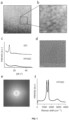
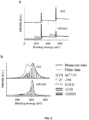
- the amorphous reduced graphene oxide (rGO) film of the invention can show a X-ray photoelectron spectroscopy (XPS) spectra as shown in FIG. 2(a) and (b) (see HTrGO).
- XPS X-ray photoelectron spectroscopy
- the amorphous reduced graphene oxide (rGO) film of the invention can have a carbon-to-oxygen ratio from 1.2 to 2.0, more particularly from from 1.6 to 1.8.
- the carbon-to-oxygen ratio can be calculated from X-ray photoelectron spectroscopy (XPS).
- the thickness of the amorphous rGO films of the invention can be measured e.g. by scanning and/or transmission electron microscopy (SEM, TEM).
- porous refers to voids, cavities, openings, or spacings, which are present in the structure of the rGO film of the invention.
- the material exhibits closely-packed pores, and the pores have a diameter equal to or less than 10 nm.
- the term "closely packed” pores as used herein has to be understood as its well-known meaning in geometry. It means that the pores are spaced apart from adjacent pores by a distance of less than the widths of the adjacent pores.
- the pore diameter may be measured by High-angle annular dark-field scanning transmission electron microscopy (HAADF-STEM). For example, a TECNAI F20 TEM operated at 200 kV may be used ( FIG. 1 (a, b)).
- XRD X-ray diffractometer
- CuK ⁇ radiation 1.540598 ⁇
- the detector used is a Pixcel which is a fast X-ray detector based on Medipix2 technology.
- substantially absent refers to a presence of equal to or less than about 1%, more particularly equal to or less than 0.1%.
- the amorphous reduced graphene oxide (rGO) film as defined above shows a X-ray diffraction spectra as shown in FIG. 1 (c) (HTrGO).
- amorphous rGO film refers to the fact that the rGO film of the invention shows a disordered structure.
- the amorphous structure of the film is the result of the hydrothermal reduction. This feature may be assessed by preparing a FIB lamella, Helios NanoLab DualBeam (LMA-INA, Zaragoza) for the cross-section study of the sample.
- the amorphous reduced graphene oxide (rGO) film as defined above shows a characteristic annular fingerprint of an amorphous material in the Fast Fourier Transform (FFT) pattern of a High-resolution transmission electron microscopy (HRTEM) image. More particularly, the amorphous reduced graphene oxide (rGO) film as defined above shows the annular fingerprint in the Fast Fourier Transform (FFT) pattern of a High-resolution transmission electron microscopy (HRTEM) image as shown FIG. 1(e) .
- Raman spectroscopy may also be used for characterizing the amorphous reduced graphene oxide (rGO) film of the invention.
- the ratio of intensity D to G (D/G) bands is a measure of the defect present in the graphene structure.
- the amorphous reduced graphene oxide (rGO) film as defined above shows a D-toG ratio of about 0.86 in the Raman spectrum. More particularly, the amorphous reduced graphene oxide (rGO) film as defined above shows the Raman spectrum as shown in FIG. 1(f) .
- the amorphous reduced graphene oxide (rGO) film of the invention is a highly porous material.
- it shows high porosity in the inner portion of the film, also referred herein to as rGO bulk.
- the high porosity is responsible for a large area-to-volume ratio, which results in a material with a very high capacitance.
- the pores are homogeneously distributed as shown in FIG. 1 .
- a “homogeneous distribution” means that the amount of pores does not substantially vary throughout different portions of the film, i.e., the pores are distributed uniformly over the entire film.
- the amorphous reduced graphene oxide (rGO) film of the invention exhibits high porosity and high electrical conductivity in electrolyte-based systems.
- the amorphous reduced graphene oxide (rGO) film of the invention when implemented in an electrode of about 25 micrometer diameter, is capable of providing a charge injection limit (CIL) from 2 to 10 mC/cm 2 , and an impedance of 10 to 100 k ⁇ at a frequency of 1kHz in an electrolyte-based system, more particular in an aqueous system.
- CIL charge injection limit
- the amorphous reduced graphene oxide (rGO) film as defined above comprises an upper film portion, a bulk portion (internal part), and a lower film portion.
- the upper film portion comprises the film portion from the upper or top surface up to the bulk portion.
- the bulk portion is the film portion placed between the upper film portion and the lower film portion; and the lower film portion is the film portion comprising from the bulk portion up to the lower or bottom surface.
- the upper and lower portions of the amorphous rGO film of the invention as defined above may prevent any possible delamination of the flakes of the inner portion while keeping the access of liquids to them, thus avoiding that the material leaves undesired residues when integrated e.g. in an implantable device. This minimizes inflammatory (local or systemic) responses from the neural tissue.
- these upper and lower portions provide mechanical stability.
- each of the upper portion and lower portion independently have a thickness from 2 to 6 nm.
- the bulk portion has a thickness from 14 to 996 nm.
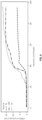
- the elemental composition of the resulting rGO film in the surfaces (upper and lower portions) and in the internal part (bulk) may be different, being the upper portion higher oxidized in comparison to the bulk.
- the elemental composition can be measured by energy dispersive x-ray spectroscopy (EDX) ( FIG. 3 ).
- the elemental composition of the bulk portion consists essentially of carbon in an amount equal to or more than about 85% of the atomic composition, and oxygen in an amount equal to or less than about 15% of the atomic composition.
- the elemental composition of each of the upper portion and lower portion of the film independently consist essentially of carbon in an amount equal to or lower than about 60% of the atomic composition and oxygen in an amount equal to or higher than about 30% of the atomic composition.
- the term "the elemental composition consists essentially of' means that specific further components can be present in the film, namely those not materially affecting the essential characteristics of the amorphous reduced graphene oxide.
- the elemental composition of the bulk portion and/or the elemental composition of the upper and lower portion of the film consists of carbon and oxygen in the amounts mentioned above.
- the present invention also relates to an electrically back-contacted conductive reduced graphene oxide (rGO) structure comprising the amorphous rGO film as previously defined, and an additional conductive support on which the rGO is deposited.
- rGO electrically back-contacted conductive reduced graphene oxide
- the term "back-contacted" as used herein means that the amorphous rGO film is placed onto the additional conductive support, such that the lower surface of the film is in contact with one of the surfaces of the conductive support.
- the additional conductive layer contributes to lowering the electrical access resistance to the bulk or inner portion of the rGO film of the invention.
- the additional conductive support is selected from the group consisting of a metal, Single Layer Graphene (SLG), few layer graphene (FLG), and multilayer graphene (MLG). More particularly, the additional conductive support is a Single Layer Graphene (SLG). SLG is commercially available.
- the particular structure of the rGO material previously described may be achieved by a process including a filtration step of graphene oxide on a membrane and subsequent transfer to a support and reduction of the material. Therefore, it also forms part of the invention a reduced graphene oxide material as defined above, which is obtainable by a process which comprises the following steps:
- composition "obtainable by the process" of the invention is used herein for defining the rGO material by its preparation process and refers to the rGO material that can be obtained through the preparation process which comprises the steps i) to v) as previously defined.
- the expressions “obtainable”, “obtained” and similar equivalent expressions are used interchangeably and, in any case, the expression “obtainable” encompasses the expression “obtained”.
- the invention also relates to the process for the preparation of the amorphous reduced graphene oxide (rGO) film as defined above, which comprises the steps i) to v) as previously defined.
- the starting graphene oxide (GO) used in step i) of the process above is commercially available.
- Graphene oxide contains high-density oxygen functional groups, like hydroxyl and epoxy group on its basal plane, and carboxyl at its edge. It is synthesized dominantly via chemical oxidation of natural graphite even though there are a few reports on alternative electrochemical oxidation.
- the graphene oxide (GO) solution of step i) can be an aqueous solution. More particularly, the graphene oxide (GO) solution used in step i) can have a concentration from 0.001 to 5 mg/mL. Typically, the volume of GO solution which is filtered goes from 5 to 1000 mL.
- the graphene oxide (GO) used in step i) can have a typical carbon-to-oxygen ratio from 0.5 to 1.0.
- the carbon-to-oxygen ratio can be calculated from X-ray photoelectron spectroscopy (XPS).
- the starting graphene oxide (GO) used in step i) can be in the form of flakes of >500 nm and ⁇ 20 pm wide and 0.3 -100 nm thick.
- the term "flake” as used herein refers to a material having a flat and thin geometry.
- the porous membrane used in step i) can be made of a material selected from the group consisting of nitrocellulose.
- the pores of the membrane used in step i) should be smaller than the size of the starting GO flakes.
- the membrane has a pore size from 0.025 pm to 200 pm.
- the filtration of step i) can be carried out at a pressure equal or lower than atmospheric pressure, e.g. at a pressure from 1 to 100 KPa,, more particularly from 1 to 10 KPa.
- step i) a GO film is formed on the membrane.
- the film can be dried out at room temperature for 2-10 hours.
- the back side of the membrane can be hydrated. More particularly, a wet paper is used for that purpose.
- Other solvents that, like water, are able to dissolve the GO which is in direct contact with the porous membrane and are able to pass through the membrane without damaging or dissolving it may also be used.
- the number of layers and the thickness of the film may be varied resulting in a higher or lower transparency.
- a higher GO concentration is filtered, a larger number of layers is formed with the result of less transparency.
- Films thicker than 200 nm have an optical transmission below about 5% with respect to the total transmission in wavelengths from 400 to 1160 nm.
- the membrane can be inverted.
- the surface of the GO film that was initially on the top becomes the bottom surface and this surface is the one which is placed in contact with the sacrificial substrate in the following step.
- sacrificial substrate as used herein means a substrate that is used to hold the reduced graphene oxide material of the invention and that is subsequently removed to produce a substrate free reduced graphene oxide material.
- the sacrificial substrate used in step ii) can be rigid or flexible. It can be electrically conductive or not. Depending on the nature of the substrate it may be used as a definitive substrate when the reduced graphene oxide material of the invention further comprises an additional layer of conductive material particularly placed at the bottom of the GO film.
- the substrate used in step ii) can be selected from the group consisting of SiO wafer, single layer graphene (SLG), few layer layer graphene (FLG), multilayer graphene (MLG), and a conductive metal compound.
- conductive metal compound that can be used as a substrate include metals e.g. platinum, gold, titanium, iridium, tungsten, stainless steel, silver, copper, nickel, and alloys or combinations thereof, and also iridium oxide, silver chloride and tin nitride.
- the substrate used in step ii) is a SiO wafer.
- Other substrates that may be used include polymers, such as polyimide or parylene C, deposited on top of SiO wafers.
- the deposition techniques can be spin coating or evaporation.
- the membrane can be optionally dried by e.g. blowing it with air/No from the side which is not in contact with the GO film towards the substrate.
- air/N2 is blowed from 1 to 60 second for this purpose.
- the transfer of the GO film from the membrane onto a sacrificial substrate of step ii) is performed by placing the GO film attached to the membrane in contact with the sacrificial substrate, whereby the GO film is placed between the membrane at the top and the sacrificial substrate at the bottom, and the membrane is pressed (e.g. in a roller) with a pressure from 1-500 Kg/cm 2 .
- step iii) the membrane is removed, whereby the GO film remains attached onto the sacrificial substrate only.
- the removal can be performed by peeling off the membrane.
- the GO film on the substrate is hydrothermally reduced in step iv).
- the reduction is carried out in the presence of water, in particular in an autoclave.
- Bases such as NH3 or acids (such as HNO3 or HCl) can also be present.
- the reduction is carried out at a temperature from 100 to 240 °C, under a pressure from 10 5 to 10 6 Pa, for a time period from 1 min to 20 h.
- the hydrothermal reduction is carried out in a sealed container, more particularly in a Teflon lined container inside of an autoclave, such that the GO film is not in direct contact with water.
- the reduction can be carried out at a temperature from 100 to 240 °C, more particularly from 100 to 150 °C, and even more particularly at about 134 °C.
- the reduction can be carried out at a pressure from 10 5 to 10 6 Pa, more particularly from 100000 to 300000 Pa.
- the hydrothermal reduction can be carried out for a time period from 1 min to 20 h.
- the properties of the rGO, in particular the capacitance of the resulting reduced GO film may be modulated.
- this is detached from the substrate. This can be done by immersing the reduced GO material (rGO) into water and recover the floating reduced GO material (rGO).
- a process for the preparation of the amorphous reduced graphene oxide (rGO) film as defined above can comprise the following steps:
- a process analogue to the process as previously described comprising steps i) to iv) may be used provided that instead of the sacrificial substrate the additional conductive layer is used. In this case, there is no need to carry out step v) (removal of the substrate to detach the rGO material).
- the electrically back-contacted conductive reduced graphene oxide (rGO) structure as defined above is obtainable by the process comprising the following steps:
- the rGO material with the additional conductive layer may be prepared either by the process as described above comprising steps i) to v) and then attaching the graphene material to the additional conductive layer, or by the process as described above comprising steps i) to iv) and then transferring the graphene material to the additional conductive layer and removing the sacrificial substrate.
- the electrically back-contacted conductive reduced graphene oxide (rGO) structure can be electrically activated in an electrolyte system, more particularly in an aqueous environment.
- This activation comprises placing the material in an electrolyte and sending electrical signals through the material/electrolyte interface.
- This has the advantage that it improves the electrical conductivity and interfacial capacitance, while lowering the interfacial impedance.
- this process can be applied with no irreversible damage of the electrode until being able to inject up to 10 mC/cm 2 , depending on the thickness of the rGO film.
- the electronic device as defined above is a neural electrode.
- the electronic device as defined above comprises a flexible substrate patterned with conductive leads, e.g. metals like Au, Pt or other conductors such as indium tin oxides, on which the rGO film or the electrically back-contacted conductive rGO-based material is deposited, and an encapsulating (also denominated passivating or insulating layer) with openings on the top.
- conductive leads e.g. metals like Au, Pt or other conductors such as indium tin oxides
- encapsulating also denominated passivating or insulating layer
- the term “flexible” refers to the ability of the device to be bended without breaking or cracking.
- the flexible substrate is made of polyimide or parylene C.
- the encapsulating layer is made of polyimide or parylene C.
- the electronic device as defined above can have a thickness from 10 to 30 ⁇ m.
- the electronic device as defined above can be an array of microelectrodes.
- the array may typically comprise from 4 to 256 microeletrodes, more particularly circular-shaped microelectrodes with a diameter ranging from 5 to 100 micrometers.
- the microelectrodes may be spaced with an interelectrode distance that can typically range from 10 to 300 micrometers.
- the electronic device may be fabricated by a process comprising the following steps:
- a wet chemical method was used to transfer the graphene from the copper foil to the SiO 2 substrate.
- a poly(methyl methacrylate) PMMA A2 (MicroChem) was deposited on the graphene/copper foil and was let dry for 12 h.
- the back side graphene was etched.
- the sample was laid at the surface of an etchant solution composed of FeCl 3 /HCl (0.5M/2M) for 2 min. The back of the sample side was then flushed with water.
- the sample was laid on the etchant solution to remove the copper for at least 6h.
- the sample was cleaned several times in water and transferred onto the SiO 2 wafer.
- the wafer was dried for 30 min at 40 °C on a hot plate and then gradually up to 180 °C annealed in a vacuum oven.
- the PMMA was dissolved in acetone and isopropanol.
- a GO film was prepared and transferred as described in steps 1 and 2 of Example 1, in which the SiO 2 wafer was substituted by the SLG/SiO 2 stack described in this example.
- the transfer method used is the one described in Hébert, et al., Advanced Functional Materials, Vol. 28 (March 2018 ).
- the GO/SLG/SiO 2 wafer was placed into an autoclave and hydrothermally reduced for 3 hours at 135 °C.
- the structural properties of the HTrGO were as in Example 1; however, the film was in this case placed on a conductive transparent layer (SLG).
- SLG conductive transparent layer
- Example 3- Microelectrode based on a HTrGO/SLG stack
- a single layer graphene (SLG) was grown as described in Example 2.
- a metallic microelectrode was defined onto a SiO 2 wafer as follows. First, the wafer was patterned with a photoresist (AZ5214 MichroChemicals GmbH) using standard optical lithography methods; a circular pattern with a diameter of 25 micrometers was open in the photoresist. Afterwards, a layer of chromium (10 nm)/gold (200 nm) was evaporated onto the wafer. Afterwards, the photoresist was removed by immersing the wafer in acetone; then in isopropanol and finally the wafer was blown dry. Then, the SLG was transferred onto the wafer with the microelectrode as described in Example 2.
- a photoresist AZ5214 MichroChemicals GmbH
- the filtered GO film was transferred onto the SLG as described in steps 1 and 2 of Example 1, in which the SiO 2 wafer is now substituted by the SLG/ SiO 2 stack described in Example 2.
- the area of the graphene-containing microelectrode was defined by using a combination of photolithography and reactive ion etching.
- a passivation of layer of polyimide PI 2611 (HD MicroSystems) was spin coated and cured to insulate electrically the metallic contacts.
- the microelectrode regions were patterned with photolithography and opened with reactive ion etching through the polyimide.
- the wafer containing the GO/SLG/metal microelectrode was placed into an autoclave and hydrothermally reduced for 3 hours at 135 °C.
- the electrochemical properties of the 25 micrometer diameter electrode were characterized in phosphate buffer solution (PBS) 0.5M with a SP-200 Bio-Logic potentiostat using a three-electrode configuration.
- the working electrode was connected to the graphene microelectrode, the counter electrode was a large platinum wire and the reference electrode was a Ag/AgCl.
- Cyclic voltammetry characterization revealed a quasi-ideal capacitive behavior with a wide potential window of 1.8 V. From these measurements, a capacitance of 50 mF/cm 2 (normalized by the geometrical area of the 25 micrometer diameter electrode) and charge storage capacitances (CSC) of 80 mC/cm 2 were obtained.
- Electrochemical impedance spectroscopy of the microelectrode revealed an impedance of 20 k ⁇ at a frequency of 1kHz.
- Example 4 Flexible microelectrode array based on a HTrGO/SLG stack
- microelectrodes An array of 64 microelectrodes, arranged in a 8x8 matrix and covering a total area of 1.44 mm 2 was prepared.
- the microelectrodes have a diameter of 25 ⁇ m and are spaced 300 ⁇ m from each other.
- PI Polyimide
- PI 2611 HD MicroSystems a 10 ⁇ m thick layer of Polyimide
- gold leads consisting of a bilayer of Ti and Au, 10 nm Ti and 200 nm Au
- SLG and the GO film transfer were followed by the SLG and the GO film transfer, and their patterning by photolithography and reactive ion etching.
- electrochemical properties charge storage capacitance, charge injection limit, and impedance
- This section presents the suitability of the microelectrode array of Example 4 to record in vivo neural activity with low noise.
- a flexible micro electrocorticography ( ⁇ LECoG) device containing the array of microelectrodes according to the invention was placed on the surface of the auditory cortex while an auditory stimulus was presented to record the neurophysiological activity on that area ( FIG. 4 (a) ).
- the device according to the invention was fabricated as explained in Example 4.
- the Pt-based device was acquired commercially (E64-500-20-60, NeuroNexus, USA).
- ⁇ ECoG microelectrocorticography
- FIG. 4 (d) and e show the signal recorded by the device according to the invention and the Pt device, respectively.
- an evoked local field potential LFP
- LFP evoked local field potential
- Only the microelectrode of the invention recorded an LFP on the offset of the audio signal, probably due to its localization on the auditory cortex.
- the intrinsic noise of the electrodes under post mortem conditions is shown overlapped on the evoked LFP for the device according to the invention and for Pt also in FIG. 4(d) and (e) , respectively.
- it had a peak-to-peak amplitude of 12 ⁇ V, while Pt reached 15 ⁇ V.
- the recording capabilities of device according to the invention can be further explored and compared with Pt studying the power spectral density (PSD) from the in vivo and post mortem signals ( FIG. 4 (f) ).
- PSD power spectral density
- FIG. 4 (f) From the analysis of the post-mortem data, rms noise of 2.9 ⁇ V was obtained for the device according to the invention compared to 3.2 ⁇ V for Pt when the PSD was integrated between 10 Hz and 10 kHz.
- a PSD study of the in-vivo data indicated that the microelectrodes of the invention were capable of capturing more neurophysiological data than the Pt ones between 20 Hz and 10 kHz. This phenomenon could also be observed in FIG.
- microelectrode arrays of example 4 were fabricated and implanted transversally in the sciatic nerve of rats in acute experiments.
- the devices selectively stimulated subsets of axons in different fascicles within the nerve while the activation of the plantar (PL), gastrocnemius (GM) and tibialis anterior (TA) muscles was recorded by electromyographic (EMG) signals ( FIG. 5 (a) ).
- the implant consisted of a long flexible and foldable stripe with 18 microelectrodes each with a diameter of 25 ⁇ m diameter according to the invention on the top side.
- the stripe was folded in a V-shape in such a way that the 18 microelectrodes were distributed in 2 arrays of 9, each facing one side of the stripe. This way, each of the 2 arrays span a total length of 1.2 mm, a length similar to the diameter of the sciatic nerve of rats.
- the microelectrodes were characterized, proving its suitability to reliably inject 8 mC/cm2 in biphasic pulses of 400 ⁇ A and 100 of ⁇ s/phase duration as well as an average impedance of 55 ⁇ 15 k ⁇ .
- the device was implanted intrafascicularly into the sciatic nerve of an anesthetized rat in such a way that the 2 arrays of 9 microelectrodes were crossing the fascicles or subfascicles responsible for the innervation of the PL, GM and TA muscles ( FIG. 5 (b,c)). Thereafter, electrical stimuli were injected in the nerve through each of the microelectrodes and the amplitude of the compound muscle action potentials (CMAP) elicited in the each of the three muscles was monitored through monopolar needles inserted into the GM, PL and TA muscle bellies.
- CMAP compound muscle action potentials
- the measured amplitudes were normalized to the maximum CMAP amplitude obtained previously by external stimulation at supramaximal intensity using stainless-steel needle electrodes in the sciatic nerve.
- the stimuli consisted of trains of 100 biphasic pulses with increasing current amplitude that ranged from 0 to 100 ⁇ A against an external reference electrode placed proximally in the nerve.
Landscapes
- Chemical & Material Sciences (AREA)
- Organic Chemistry (AREA)
- Engineering & Computer Science (AREA)
- Inorganic Chemistry (AREA)
- Nanotechnology (AREA)
- Materials Engineering (AREA)
- Power Engineering (AREA)
- Microelectronics & Electronic Packaging (AREA)
- General Life Sciences & Earth Sciences (AREA)
- Geology (AREA)
- Life Sciences & Earth Sciences (AREA)
- Crystallography & Structural Chemistry (AREA)
- Carbon And Carbon Compounds (AREA)
- Electrotherapy Devices (AREA)
- Investigating Or Analyzing Materials By The Use Of Fluid Adsorption Or Reactions (AREA)
Claims (13)
- Amorphe Folie aus reduziertem Graphenoxid (rGO) zur Verwendung in einer implantierbaren elektronischen Vorrichtung zur neuronalen Anbindung, wobei die Folie eine Gesamtdicke von 20 nm bis 5 Mikrometer hat und Poren mit einem Durchmesser von gleich oder kleiner als 10 nm aufweist.
- Amorphe Folie aus reduziertem Graphenoxid (rGO) nach Anspruch 1, die ein Röntgenbeugungsspektrum zeigt, in dem das Vorhandensein eines Peaks bei 11 ± 0,5, σ = 4, Grad 2 Theta, gemessen in einem Röntgen-Diffraktometer mit CuKα-Strahlung (1,540598 Å), charakteristisch für nicht-reduziertes Graphenoxid, gleich oder kleiner als 1 % Fläche/Fläche, vorzugsweise gleich oder kleiner als 0,1 % Fläche/Fläche ist.
- Amorphe Folie aus reduziertem Graphenoxid (rGO) nach einem der Ansprüche 1 oder 2, die einen oberen Folienabschnitt, einen unteren Folienabschnitt und einen Hauptabschnitt aufweist, der zwischen dem oberen Folienabschnitt und dem unteren Folienabschnitt sitzt,wobei die Elementzusammensetzung des Hauptabschnitts im Wesentlichen aus Kohlenstoff in einer Menge von gleich oder mehr als 85% der Elementzusammensetzung und Sauerstoff in einer Menge von gleich oder kleiner als 15% der Elementzusammensetzung besteht, undwobei die Elementzusammensetzung von jeweils dem oberen Abschnitt und unteren Abschnitt der Folie unabhängig im Wesentlichen aus Kohlenstoff in einer Menge von gleich oder weniger als 60% der Elementzusammensetzung und Sauerstoff in einer Menge von gleich oder mehr als 30% der Elementzusammensetzung besteht.
- Amorphe Folie aus reduziertem Graphenoxid (rGO) nach Anspruch 3, wobei der obere Folienabschnitt und untere Folienabschnitt unabhängig jeweils eine Dicke von 2 bis 6 nm haben.
- Elektrisch rückkontaktierte leitfähige Struktur aus reduziertem Graphenoxid (rGO), aufweisend die amorphe Folie aus reduziertem Graphenoxid (rGO), nach einem der Ansprüche 1 bis 4, und einen zusätzlichen leitfähigen Träger, auf dem das rGO abgeschieden ist.
- Elektrisch rückkontaktierte leitfähige Struktur nach Anspruch 5, wobei der zusätzliche leitfähige Träger ausgewählt ist aus der Gruppe bestehend aus einem Metall, aus Einzelschicht-Graphen (SLG), Graphen mit wenigen Schichten (FLG) und Graphen mit vielen Schichten (MLG).
- Verfahren zur Herstellung einer amorphen Folie aus reduziertem Graphenoxid (rGO) nach einem der Ansprüche 1-4, das die folgenden Schritte umfasst:i) Filtern einer Lösung aus Graphenoxid (GO) durch eine poröse Membran, wodurch sich eine GO-Folie auf der Membranoberseite bildet;ii) Überführen der GO-Folie von der Membran auf ein Opfersubstrat, wobei die GO-Folie zwischen der Membran an der Oberseite und dem Opfersubstrat an der Unterseite platziert wird;iii) Entfernen der Membran, wobei die GO-Folie am Opfersubstrat haften bleibt;iv) hydrothermales Reduzieren der GO-Folie zur Bildung eines reduzierten GO-Materials (rGO); undv) Ablösen des rGO-Materials vom Opfersubstrat.
- Verfahren zur Herstellung einer elektrisch rückkontaktierten leitfähigen Struktur aus reduziertem Graphenoxid (rGO) nach Anspruch 5 oder 6, das die folgenden Schritte umfasst:i') Filtern einer Lösung aus Graphenoxid (GO) durch eine poröse Membran, wodurch sich eine GO-Folie auf der Membranoberseite bildet;ii') Überführen der GO-Folie von der Membran auf den zusätzlichen leitfähigen Träger, wobei die GO-Folie zwischen der Membran an der Oberseite und dem zusätzlichen leitfähigen Träger an der Unterseite platziert wird;iii') Entfernen der Membran, wobei die GO-Folie an dem zusätzlichen leitfähigen Träger haften bleibt, undiv') hydrothermales Reduzieren der GO-Folie zur Bildung eines reduzierten GO-Materials (rGO).
- Verfahren nach einem der Ansprüche 7-8, wobei die hydrothermale Reduktion in einem dicht verschlossenen Behälter im Inneren eines Autoklaven ausgeführt wird und die GO-Folie nicht in direktem Kontakt mit Wasser ist.
- Elektronische Vorrichtung zum Erfassen, Empfangen und/oder Induzieren elektrischer Signale, aufweisend die amorphe Folie aus reduziertem Graphenoxid (rGO) nach einem der Ansprüche 1 bis 4 oder die elektrisch rückkontaktierte leitfähige Struktur aus reduziertem Graphenoxid (rGO) nach den Ansprüchen 5-6.
- Elektronische Vorrichtung nach Anspruch 10, bei der es sich um eine neuronale Elektrode handelt.
- Elektronische Vorrichtung nach einem der Ansprüche 10-11, die einen flexiblen Träger, der mit leitfähigen Bahnen strukturiert ist, auf denen die amorphe Folie aus reduziertem Graphenoxid (rGO) oder die elektrisch rückkontaktierte leitfähige rGO-Struktur abgeschieden ist, und eine Verkapselungsschicht mit Öffnungen an der Oberseite aufweist.
- Verwendung einer amorphen Folie aus reduziertem Graphenoxid (rGO) in einer implantierbaren elektronischen Vorrichtung zur neuronalen Anbindung, wobei die Folie eine Gesamtdicke von 20 nm bis 5 Mikrometer hat und Poren mit einem Durchmesser von gleich oder kleiner als 10 nm aufweist.
Priority Applications (11)
| Application Number | Priority Date | Filing Date | Title |
|---|---|---|---|
| EP19382146.9A EP3702327B1 (de) | 2019-02-27 | 2019-02-27 | Amorphe hochporöse folie mit reduziertem graphenoxid und deren anwendungen |
| DE19382146.9T DE19382146T1 (de) | 2019-02-27 | 2019-02-27 | Amorphe hochporöse folie mit reduziertem graphenoxid und deren anwendungen |
| EP25159718.3A EP4610225A3 (de) | 2019-02-27 | 2019-02-27 | Amorphe hochporöse folie aus reduziertem graphenoxid und ihre anwendungen |
| ES19382146T ES3017700T3 (en) | 2019-02-27 | 2019-02-27 | Amorphous highly porous reduced graphene oxide film and its applications |
| PCT/EP2020/055195 WO2020174066A1 (en) | 2019-02-27 | 2020-02-27 | Reduced graphene oxide film comprising a stack of rgo layers and its applications |
| KR1020217030821A KR102601906B1 (ko) | 2019-02-27 | 2020-02-27 | rGO층의 스택을 포함하는 환원된 산화그래핀 필름 및 그 응용 |
| SG11202109019XA SG11202109019XA (en) | 2019-02-27 | 2020-02-27 | Reduced graphene oxide film comprising a stack of rgo layers and its applications |
| JP2021549933A JP7579796B2 (ja) | 2019-02-27 | 2020-02-27 | rGO層のスタックを含む還元型酸化グラフェン膜及びその用途 |
| US17/310,894 US12486174B2 (en) | 2019-02-27 | 2020-02-27 | Reduced graphene oxide film comprising a stack of rGO layers and its applications |
| CN202080030752.6A CN114096483B (zh) | 2019-02-27 | 2020-02-27 | 包含还原氧化石墨烯层堆叠的还原氧化石墨烯膜片及其应用 |
| US19/376,341 US20260054992A1 (en) | 2019-02-27 | 2025-10-31 | Reduced graphene oxide film comprising a stack of rgo layers and its applications |
Applications Claiming Priority (1)
| Application Number | Priority Date | Filing Date | Title |
|---|---|---|---|
| EP19382146.9A EP3702327B1 (de) | 2019-02-27 | 2019-02-27 | Amorphe hochporöse folie mit reduziertem graphenoxid und deren anwendungen |
Related Child Applications (1)
| Application Number | Title | Priority Date | Filing Date |
|---|---|---|---|
| EP25159718.3A Division EP4610225A3 (de) | 2019-02-27 | 2019-02-27 | Amorphe hochporöse folie aus reduziertem graphenoxid und ihre anwendungen |
Publications (3)
| Publication Number | Publication Date |
|---|---|
| EP3702327A1 EP3702327A1 (de) | 2020-09-02 |
| EP3702327B1 true EP3702327B1 (de) | 2025-02-26 |
| EP3702327C0 EP3702327C0 (de) | 2025-02-26 |
Family
ID=65766955
Family Applications (2)
| Application Number | Title | Priority Date | Filing Date |
|---|---|---|---|
| EP19382146.9A Active EP3702327B1 (de) | 2019-02-27 | 2019-02-27 | Amorphe hochporöse folie mit reduziertem graphenoxid und deren anwendungen |
| EP25159718.3A Pending EP4610225A3 (de) | 2019-02-27 | 2019-02-27 | Amorphe hochporöse folie aus reduziertem graphenoxid und ihre anwendungen |
Family Applications After (1)
| Application Number | Title | Priority Date | Filing Date |
|---|---|---|---|
| EP25159718.3A Pending EP4610225A3 (de) | 2019-02-27 | 2019-02-27 | Amorphe hochporöse folie aus reduziertem graphenoxid und ihre anwendungen |
Country Status (9)
| Country | Link |
|---|---|
| US (2) | US12486174B2 (de) |
| EP (2) | EP3702327B1 (de) |
| JP (1) | JP7579796B2 (de) |
| KR (1) | KR102601906B1 (de) |
| CN (1) | CN114096483B (de) |
| DE (1) | DE19382146T1 (de) |
| ES (1) | ES3017700T3 (de) |
| SG (1) | SG11202109019XA (de) |
| WO (1) | WO2020174066A1 (de) |
Families Citing this family (6)
| Publication number | Priority date | Publication date | Assignee | Title |
|---|---|---|---|---|
| EP4015033B1 (de) * | 2020-12-21 | 2025-07-16 | INBRAIN Neuroelectronics SL | Flexibler elektrodenträger |
| US20220322505A1 (en) * | 2021-03-31 | 2022-10-06 | National University Of Singapore | Thermal material and a method of making the same |
| EP4098316B1 (de) * | 2021-06-03 | 2024-05-15 | INBRAIN Neuroelectronics SL | Nervenstimulationssystem |
| CN114804080B (zh) * | 2022-04-14 | 2024-09-24 | 伊诺福科光学技术有限公司 | 一种低成本大面积制备石墨烯薄膜的方法 |
| CN114722339B (zh) * | 2022-04-18 | 2024-12-17 | 西南石油大学 | 一种碳氧比能谱中氢峰基线估计方法 |
| EP4523731A1 (de) * | 2023-09-18 | 2025-03-19 | INBRAIN Neuroelectronics SL | Neuronale schnittstelle und geschlossenes regelkreis-decodierungs- und neuromodulations-/neurostimulationssystem damit |
Citations (1)
| Publication number | Priority date | Publication date | Assignee | Title |
|---|---|---|---|---|
| WO2016011124A1 (en) * | 2014-07-17 | 2016-01-21 | The Research Foundation For The State University Of New York | Porous graphene based composite membranes for nanofiltration, desalination, and pervaporation |
Family Cites Families (20)
| Publication number | Priority date | Publication date | Assignee | Title |
|---|---|---|---|---|
| US9388049B2 (en) | 2013-06-12 | 2016-07-12 | Research & Business Foundation Sungkyunkwan University | Method of producing graphene using surfactant |
| KR101465205B1 (ko) | 2013-06-13 | 2014-11-25 | 성균관대학교산학협력단 | 방향족 작용기를 함유하는 계면활성제를 이용한 그래핀 제조 방법 |
| US10214422B2 (en) * | 2013-10-16 | 2019-02-26 | Research & Business Foundation Sungkyunkwan University | Interlayer distance controlled graphene, supercapacitor and method of producing the same |
| TWI531407B (zh) | 2014-11-20 | 2016-05-01 | 中原大學 | 石墨烯過濾膜及其製作方法 |
| KR20160071939A (ko) * | 2014-12-12 | 2016-06-22 | 주식회사 엘지화학 | 부분 산화 그래핀 및 이의 제조 방법 |
| KR102314988B1 (ko) * | 2014-12-26 | 2021-10-21 | 솔브레인 주식회사 | 용매 정제용 그래핀 멤브레인 필름과 그 제조방법 및 이를 이용한 용매 정제 시스템 |
| JP6840476B2 (ja) * | 2015-07-16 | 2021-03-10 | 株式会社半導体エネルギー研究所 | 蓄電装置の作製方法 |
| KR20170010680A (ko) * | 2015-07-20 | 2017-02-01 | 한국기계연구원 | 신축성 향상을 위한 메타 계면 구조물 및 그 제작방법 |
| EP3331823A1 (de) * | 2015-08-06 | 2018-06-13 | King Abdullah University Of Science And Technology | Verfahren zur herstellung von mikrostruktur-arrays auf der oberfläche von dünnschichtmaterial |
| CN105084355B (zh) * | 2015-09-11 | 2017-12-19 | 四川大学 | 层间距可控的稳定氧化石墨烯膜及其制备方法 |
| CN105542333B (zh) | 2015-12-15 | 2018-02-09 | 东华大学 | 一种还原氧化石墨烯复合薄膜及其制备方法 |
| CA3006997A1 (en) * | 2015-12-22 | 2017-06-29 | The Regents Of The University Of California | Cellular graphene films |
| US10010859B2 (en) * | 2015-12-28 | 2018-07-03 | Nanotek Instruments, Inc. | Integral 3D graphene-carbon hybrid foam and devices containing same |
| US9847184B2 (en) * | 2016-02-01 | 2017-12-19 | Nanotek Instruments, Inc. | Supercapacitor electrode having highly oriented and closely packed graphene sheets and production process |
| KR101888743B1 (ko) * | 2016-07-28 | 2018-08-14 | 연세대학교 산학협력단 | 다공성 그래핀 및 탄소질을 포함하는 복합체 |
| AU2017320334A1 (en) * | 2016-08-30 | 2019-03-14 | Swinburne University Of Technology | Porous graphene-based films and processes for preparing the films |
| CN106430161B (zh) * | 2016-09-09 | 2018-05-22 | 浙江理工大学 | 一种基于双层屈曲结构的还原氧化石墨烯薄膜的心尖搏动传感器 |
| US20210134537A1 (en) * | 2017-03-01 | 2021-05-06 | B.G. Negev Technologies And Applications Ltd., At Ben-Gurion University | An electrode and an electrochemical capacitor comprising the electrode |
| CN106865537B (zh) * | 2017-03-17 | 2019-05-28 | 吉林大学 | 一种高强度石墨烯基复合纸的制备方法 |
| CN107261857B (zh) | 2017-05-10 | 2020-06-30 | 四川大学 | 用于一价与多价金属离子分离的改性石墨烯膜及其制备方法 |
-
2019
- 2019-02-27 DE DE19382146.9T patent/DE19382146T1/de active Pending
- 2019-02-27 ES ES19382146T patent/ES3017700T3/es active Active
- 2019-02-27 EP EP19382146.9A patent/EP3702327B1/de active Active
- 2019-02-27 EP EP25159718.3A patent/EP4610225A3/de active Pending
-
2020
- 2020-02-27 CN CN202080030752.6A patent/CN114096483B/zh active Active
- 2020-02-27 SG SG11202109019XA patent/SG11202109019XA/en unknown
- 2020-02-27 JP JP2021549933A patent/JP7579796B2/ja active Active
- 2020-02-27 US US17/310,894 patent/US12486174B2/en active Active
- 2020-02-27 WO PCT/EP2020/055195 patent/WO2020174066A1/en not_active Ceased
- 2020-02-27 KR KR1020217030821A patent/KR102601906B1/ko active Active
-
2025
- 2025-10-31 US US19/376,341 patent/US20260054992A1/en active Pending
Patent Citations (1)
| Publication number | Priority date | Publication date | Assignee | Title |
|---|---|---|---|---|
| WO2016011124A1 (en) * | 2014-07-17 | 2016-01-21 | The Research Foundation For The State University Of New York | Porous graphene based composite membranes for nanofiltration, desalination, and pervaporation |
Non-Patent Citations (4)
| Title |
|---|
| BADIA ET AL.: "Comparative analysis of transverse intrafascicular multichannel, longitudinal intrafascicular and multipolar cuff electrodes for the selective stimulation of nerve fascicles", J NEURL ENG, June 2011 (2011-06-01) * |
| HEBERT ET AL., ADVANCED FUNCTIONAL MATERIALS, vol. 28, March 2018 (2018-03-01) * |
| HEBERT ET AL.: "Flexible Graphene Solution-Gated Field-Effect Transistors: Efficient Transducers for Micro-Electrocorticography", ADVANCED FUNCTIONAL MATERIALS, vol. 28, no. 12, March 2018 (2018-03-01) * |
| NING-JING SONG ET AL: "Thermally reduced graphene oxide films as flexible lateral heat spreaders", JOURNAL OF MATERIALS CHEMISTRY A, vol. 2, no. 39, 1 January 2014 (2014-01-01), GB, pages 16563 - 16568, XP055584086, ISSN: 2050-7488, DOI: 10.1039/C4TA02693D * |
Also Published As
| Publication number | Publication date |
|---|---|
| KR20220002273A (ko) | 2022-01-06 |
| SG11202109019XA (en) | 2021-09-29 |
| DE19382146T1 (de) | 2021-01-14 |
| JP7579796B2 (ja) | 2024-11-08 |
| KR102601906B1 (ko) | 2023-11-14 |
| JP2022527433A (ja) | 2022-06-02 |
| EP4610225A2 (de) | 2025-09-03 |
| US20220144644A1 (en) | 2022-05-12 |
| WO2020174066A1 (en) | 2020-09-03 |
| EP3702327A1 (de) | 2020-09-02 |
| CN114096483A (zh) | 2022-02-25 |
| EP4610225A3 (de) | 2025-10-08 |
| ES3017700T3 (en) | 2025-05-13 |
| EP3702327C0 (de) | 2025-02-26 |
| US20260054992A1 (en) | 2026-02-26 |
| CN114096483B (zh) | 2023-10-10 |
| US12486174B2 (en) | 2025-12-02 |
Similar Documents
| Publication | Publication Date | Title |
|---|---|---|
| EP3702327B1 (de) | Amorphe hochporöse folie mit reduziertem graphenoxid und deren anwendungen | |
| US8751015B2 (en) | Graphene electrodes on a planar cubic silicon carbide (3C-SiC) long term implantable neuronal prosthetic device | |
| Yi et al. | A flexible and implantable microelectrode arrays using high-temperature grown vertical carbon nanotubes and a biocompatible polymer substrate | |
| EP2674393A1 (de) | Micro-Stimulation und Datenerfassung aus biologischen Zellen | |
| JP7546563B2 (ja) | 金属化グラフェン繊維の作製方法および生体電子用途 | |
| US12065745B2 (en) | Porous platinum nanorod electrode array flexible sensor devices and fabrication | |
| US20240268740A1 (en) | An electrochemically activated and reduced graphene oxide structure | |
| EP2394696A1 (de) | Vorrichtung zur Stimulierung oder Aufzeichnung eines Signals an oder von einem lebenden Gewebe | |
| Ahani et al. | Flexible PET/ITO electrode array for implantable biomedical applications | |
| HK40067175A (en) | Reduced graphene oxide film comprising a stack of rgo layers and its applications | |
| HK40067175B (zh) | 包含还原氧化石墨烯层堆叠的还原氧化石墨烯膜片及其应用 | |
| Viana et al. | Graphene-based thin film microelectrode technology for in vivo high resolution neural recording and stimulation | |
| Negi et al. | INCREASE IN LONGIVITY OF IMPLANTABLE NEURAL DEVICE USING NOVEL MATERIAL | |
| Viana et al. | Graphene-based thin film microelectrode technology forin vivohigh resolution neural recording and stimulation | |
| WO2024215255A1 (en) | Neural electrode, neural device and methods of fabrication thereof | |
| Xu et al. | Novel structure of carbon nanotube micro electrode for high-resolution stimulation of neurons | |
| Bhandari et al. | A novel surface modification method to achieve low impedance neural microelectrode arrays | |
| Motlagh et al. | Titre | |
| de Asis et al. | Electrical stimulation of brain tissue with carbon nanofiber microbrush arrays | |
| Murphy et al. | Vitamin C-Reduced Graphene Oxide Coatings Improve the Performance and Stability of Multimodal Microelectrodes for Neural Recording, Stimulation, and Dopamine Sensing |
Legal Events
| Date | Code | Title | Description |
|---|---|---|---|
| PUAI | Public reference made under article 153(3) epc to a published international application that has entered the european phase |
Free format text: ORIGINAL CODE: 0009012 |
|
| STAA | Information on the status of an ep patent application or granted ep patent |
Free format text: STATUS: THE APPLICATION HAS BEEN PUBLISHED |
|
| AK | Designated contracting states |
Kind code of ref document: A1 Designated state(s): AL AT BE BG CH CY CZ DE DK EE ES FI FR GB GR HR HU IE IS IT LI LT LU LV MC MK MT NL NO PL PT RO RS SE SI SK SM TR |
|
| AX | Request for extension of the european patent |
Extension state: BA ME |
|
| REG | Reference to a national code |
Ref country code: DE Ref legal event code: R210 Ref country code: DE Ref legal event code: R210 Ref document number: 602019066442 Country of ref document: DE |
|
| STAA | Information on the status of an ep patent application or granted ep patent |
Free format text: STATUS: REQUEST FOR EXAMINATION WAS MADE |
|
| 17P | Request for examination filed |
Effective date: 20210222 |
|
| RBV | Designated contracting states (corrected) |
Designated state(s): AL AT BE BG CH CY CZ DE DK EE ES FI FR GB GR HR HU IE IS IT LI LT LU LV MC MK MT NL NO PL PT RO RS SE SI SK SM TR |
|
| STAA | Information on the status of an ep patent application or granted ep patent |
Free format text: STATUS: EXAMINATION IS IN PROGRESS |
|
| 17Q | First examination report despatched |
Effective date: 20210409 |
|
| REG | Reference to a national code |
Ref country code: AT Ref legal event code: EECC Ref document number: AT T Effective date: 20210515 |
|
| REG | Reference to a national code |
Ref country code: DE Ref legal event code: R079 Free format text: PREVIOUS MAIN CLASS: C01B0032230000 Ref document number: 602019066442 Country of ref document: DE Ipc: H01G0011360000 |
|
| RIC1 | Information provided on ipc code assigned before grant |
Ipc: C01B 32/198 20170101ALI20240801BHEP Ipc: C01B 32/192 20170101ALI20240801BHEP Ipc: C01B 32/23 20170101ALI20240801BHEP Ipc: H01G 11/36 20130101AFI20240801BHEP |
|
| GRAP | Despatch of communication of intention to grant a patent |
Free format text: ORIGINAL CODE: EPIDOSNIGR1 |
|
| STAA | Information on the status of an ep patent application or granted ep patent |
Free format text: STATUS: GRANT OF PATENT IS INTENDED |
|
| INTG | Intention to grant announced |
Effective date: 20241016 |
|
| GRAS | Grant fee paid |
Free format text: ORIGINAL CODE: EPIDOSNIGR3 |
|
| GRAA | (expected) grant |
Free format text: ORIGINAL CODE: 0009210 |
|
| STAA | Information on the status of an ep patent application or granted ep patent |
Free format text: STATUS: THE PATENT HAS BEEN GRANTED |
|
| REG | Reference to a national code |
Ref country code: DE Ref legal event code: R082 Ref document number: 602019066442 Country of ref document: DE |
|
| AK | Designated contracting states |
Kind code of ref document: B1 Designated state(s): AL AT BE BG CH CY CZ DE DK EE ES FI FR GB GR HR HU IE IS IT LI LT LU LV MC MK MT NL NO PL PT RO RS SE SI SK SM TR |
|
| REG | Reference to a national code |
Ref country code: GB Ref legal event code: FG4D |
|
| REG | Reference to a national code |
Ref country code: CH Ref legal event code: EP |
|
| REG | Reference to a national code |
Ref country code: DE Ref legal event code: R096 Ref document number: 602019066442 Country of ref document: DE |
|
| REG | Reference to a national code |
Ref country code: IE Ref legal event code: FG4D |
|
| REG | Reference to a national code |
Ref country code: CH Ref legal event code: PK Free format text: BERICHTIGUNGEN |
|
| RIN2 | Information on inventor provided after grant (corrected) |
Inventor name: KOSTARELOS, KOSTANTINOS Inventor name: VIANA, DAMIA Inventor name: GARRIDO ARIZA, JOSE ANTONIO Inventor name: WALSTON, STEVEN TREMAYNE Inventor name: BUSSY, CYRILL Inventor name: BULLOCK, CHRISTOPHER JOHN |
|
| U01 | Request for unitary effect filed |
Effective date: 20250321 |
|
| U07 | Unitary effect registered |
Designated state(s): AT BE BG DE DK EE FI FR IT LT LU LV MT NL PT RO SE SI Effective date: 20250404 |
|
| REG | Reference to a national code |
Ref country code: ES Ref legal event code: FG2A Ref document number: 3017700 Country of ref document: ES Kind code of ref document: T3 Effective date: 20250513 |
|
| U20 | Renewal fee for the european patent with unitary effect paid |
Year of fee payment: 7 Effective date: 20250516 |
|
| PG25 | Lapsed in a contracting state [announced via postgrant information from national office to epo] |
Ref country code: RS Free format text: LAPSE BECAUSE OF FAILURE TO SUBMIT A TRANSLATION OF THE DESCRIPTION OR TO PAY THE FEE WITHIN THE PRESCRIBED TIME-LIMIT Effective date: 20250526 |
|
| PG25 | Lapsed in a contracting state [announced via postgrant information from national office to epo] |
Ref country code: PL Free format text: LAPSE BECAUSE OF FAILURE TO SUBMIT A TRANSLATION OF THE DESCRIPTION OR TO PAY THE FEE WITHIN THE PRESCRIBED TIME-LIMIT Effective date: 20250226 |
|
| PGFP | Annual fee paid to national office [announced via postgrant information from national office to epo] |
Ref country code: ES Payment date: 20250506 Year of fee payment: 7 Ref country code: GB Payment date: 20250407 Year of fee payment: 7 |
|
| PG25 | Lapsed in a contracting state [announced via postgrant information from national office to epo] |
Ref country code: IS Free format text: LAPSE BECAUSE OF FAILURE TO SUBMIT A TRANSLATION OF THE DESCRIPTION OR TO PAY THE FEE WITHIN THE PRESCRIBED TIME-LIMIT Effective date: 20250626 Ref country code: NO Free format text: LAPSE BECAUSE OF FAILURE TO SUBMIT A TRANSLATION OF THE DESCRIPTION OR TO PAY THE FEE WITHIN THE PRESCRIBED TIME-LIMIT Effective date: 20250526 |
|
| PG25 | Lapsed in a contracting state [announced via postgrant information from national office to epo] |
Ref country code: HR Free format text: LAPSE BECAUSE OF FAILURE TO SUBMIT A TRANSLATION OF THE DESCRIPTION OR TO PAY THE FEE WITHIN THE PRESCRIBED TIME-LIMIT Effective date: 20250226 |
|
| PG25 | Lapsed in a contracting state [announced via postgrant information from national office to epo] |
Ref country code: GR Free format text: LAPSE BECAUSE OF FAILURE TO SUBMIT A TRANSLATION OF THE DESCRIPTION OR TO PAY THE FEE WITHIN THE PRESCRIBED TIME-LIMIT Effective date: 20250527 |
|
| PGFP | Annual fee paid to national office [announced via postgrant information from national office to epo] |
Ref country code: CH Payment date: 20250505 Year of fee payment: 7 |
|
| PG25 | Lapsed in a contracting state [announced via postgrant information from national office to epo] |
Ref country code: SM Free format text: LAPSE BECAUSE OF FAILURE TO SUBMIT A TRANSLATION OF THE DESCRIPTION OR TO PAY THE FEE WITHIN THE PRESCRIBED TIME-LIMIT Effective date: 20250226 |
|
| PG25 | Lapsed in a contracting state [announced via postgrant information from national office to epo] |
Ref country code: CZ Free format text: LAPSE BECAUSE OF FAILURE TO SUBMIT A TRANSLATION OF THE DESCRIPTION OR TO PAY THE FEE WITHIN THE PRESCRIBED TIME-LIMIT Effective date: 20250226 |
|
| PG25 | Lapsed in a contracting state [announced via postgrant information from national office to epo] |
Ref country code: SK Free format text: LAPSE BECAUSE OF FAILURE TO SUBMIT A TRANSLATION OF THE DESCRIPTION OR TO PAY THE FEE WITHIN THE PRESCRIBED TIME-LIMIT Effective date: 20250226 |
|
| PG25 | Lapsed in a contracting state [announced via postgrant information from national office to epo] |
Ref country code: MC Free format text: LAPSE BECAUSE OF FAILURE TO SUBMIT A TRANSLATION OF THE DESCRIPTION OR TO PAY THE FEE WITHIN THE PRESCRIBED TIME-LIMIT Effective date: 20250226 |
|
| PLBE | No opposition filed within time limit |
Free format text: ORIGINAL CODE: 0009261 |
|
| STAA | Information on the status of an ep patent application or granted ep patent |
Free format text: STATUS: NO OPPOSITION FILED WITHIN TIME LIMIT |
|
| REG | Reference to a national code |
Ref country code: CH Ref legal event code: L10 Free format text: ST27 STATUS EVENT CODE: U-0-0-L10-L00 (AS PROVIDED BY THE NATIONAL OFFICE) Effective date: 20260107 |
|
| PG25 | Lapsed in a contracting state [announced via postgrant information from national office to epo] |
Ref country code: IE Free format text: LAPSE BECAUSE OF NON-PAYMENT OF DUE FEES Effective date: 20250227 |
|
| 26N | No opposition filed |
Effective date: 20251127 |
|
| REG | Reference to a national code |
Ref country code: CH Ref legal event code: U11 Free format text: ST27 STATUS EVENT CODE: U-0-0-U10-U11 (AS PROVIDED BY THE NATIONAL OFFICE) Effective date: 20260301 |