EP3702279B1 - Unbemanntes flugzeug - Google Patents
Unbemanntes flugzeug Download PDFInfo
- Publication number
- EP3702279B1 EP3702279B1 EP18934520.0A EP18934520A EP3702279B1 EP 3702279 B1 EP3702279 B1 EP 3702279B1 EP 18934520 A EP18934520 A EP 18934520A EP 3702279 B1 EP3702279 B1 EP 3702279B1
- Authority
- EP
- European Patent Office
- Prior art keywords
- arms
- aerial vehicle
- unmanned aerial
- group
- actuator
- Prior art date
- Legal status (The legal status is an assumption and is not a legal conclusion. Google has not performed a legal analysis and makes no representation as to the accuracy of the status listed.)
- Active
Links
Images





Classifications
-
- B—PERFORMING OPERATIONS; TRANSPORTING
- B64—AIRCRAFT; AVIATION; COSMONAUTICS
- B64C—AEROPLANES; HELICOPTERS
- B64C27/00—Rotorcraft; Rotors peculiar thereto
- B64C27/04—Helicopters
- B64C27/12—Rotor drives
- B64C27/16—Drive of rotors by means, e.g. propellers, mounted on rotor blades
-
- B—PERFORMING OPERATIONS; TRANSPORTING
- B64—AIRCRAFT; AVIATION; COSMONAUTICS
- B64U—UNMANNED AERIAL VEHICLES [UAV]; EQUIPMENT THEREFOR
- B64U10/00—Type of UAV
- B64U10/10—Rotorcrafts
- B64U10/13—Flying platforms
- B64U10/14—Flying platforms with four distinct rotor axes, e.g. quadcopters
-
- B—PERFORMING OPERATIONS; TRANSPORTING
- B64—AIRCRAFT; AVIATION; COSMONAUTICS
- B64U—UNMANNED AERIAL VEHICLES [UAV]; EQUIPMENT THEREFOR
- B64U30/00—Means for producing lift; Empennages; Arrangements thereof
- B64U30/20—Rotors; Rotor supports
- B64U30/29—Constructional aspects of rotors or rotor supports; Arrangements thereof
- B64U30/296—Rotors with variable spatial positions relative to the UAV body
-
- B—PERFORMING OPERATIONS; TRANSPORTING
- B64—AIRCRAFT; AVIATION; COSMONAUTICS
- B64U—UNMANNED AERIAL VEHICLES [UAV]; EQUIPMENT THEREFOR
- B64U2101/00—UAVs specially adapted for particular uses or applications
- B64U2101/60—UAVs specially adapted for particular uses or applications for transporting passengers; for transporting goods other than weapons
- B64U2101/64—UAVs specially adapted for particular uses or applications for transporting passengers; for transporting goods other than weapons for parcel delivery or retrieval
-
- B—PERFORMING OPERATIONS; TRANSPORTING
- B64—AIRCRAFT; AVIATION; COSMONAUTICS
- B64U—UNMANNED AERIAL VEHICLES [UAV]; EQUIPMENT THEREFOR
- B64U60/00—Undercarriages
- B64U60/50—Undercarriages with landing legs
Definitions
- the present invention relates to an unmanned aerial vehicle.
- a drone includes a holding mechanism configured to hold a package, and is capable of dropping the package after landing.
- a holding mechanism configured to hold a package, and is capable of dropping the package after landing.
- US 2016/0159472 A1 states a reconfigurable unmanned aircraft system and a system and method for configuring a reconfigurable unmanned aircraft system, wherein the aircraft is selectively reconfigurable to modify flight characteristics, wherein the aircraft comprises a set of rotors and the position of at least one rotor relative to the base can be modified by at least one of translation of the rotor relative to the boom, pivoting of the boom relative to the base, and translation of the boom relative to the base; so that flight characteristics can be modified by configuration of at least one rotor relative to the base.
- US 9,550,561 B1 states a system and method for determining the center of gravity of a payload engaged by an automated aerial vehicle and adjusting components of the automated aerial vehicle and/or the engagement location with the payload so that the center of gravity of the payload is within a defined position with respect to the center of gravity of the automated aerial vehicle.
- UAV generally includes a UAV chassis including an upper portion, a plurality of propulsion members configured to provide lift for the UAV chassis, and a parcel carrier configured for being selectively coupled to and removed from the UAV chassis.
- KR 101 852 844 B1 states a fixing device for an unmanned aerial vehicle, which includes a first cargo contact unit and a second cargo contact unit, coming into contact with a box-shaped cargo; an elasticity applying unit applying elasticity between the first cargo contact unit and a second cargo contact unit and coming into contact with the first cargo contact unit and the second cargo contact unit; a magnetic force applying unit installed in at least one among the first cargo contact unit and the second cargo contact unit and applying a magnetic force between the first cargo contact unit and the second cargo contact unit; a control unit controlling a motion of the magnetic force applying unit; and a main body, wherein the fixing device for an unmanned aerial vehicle can stably fix and release various sizes of the box-shaped cargos to and from an unmanned aerial vehicle by using the elasticity generated by a spring and the magnetic force generated by an electromagnet.
- a large drone is excellent in stability of flying.
- the large drone cannot easily turn in a compact space and requires a larger space for flying or takeoff and landing, that is, has low maneuverability. Therefore, the large drone is not suitable for conveyance of a small package.
- the present invention has an object to achieve both stability and maneuverability of flying.
- FIG. 1 is a side view for illustrating an unmanned aerial vehicle according to a first embodiment of the present invention.
- FIG. 2 is a plan view for illustrating the unmanned aerial vehicle illustrated in FIG. 1 .
- the unmanned aerial vehicle is an aerial vehicle on which a person is not on board.
- the unmanned aerial vehicle may be a drone driven by a battery or driven by an engine.
- the unmanned aerial vehicle includes a plurality of rotary wings 10 (for example, propellers), which are configured to generate a downward airstream.
- the rotary wings 10 are driven by a motor and a battery (not shown).
- the unmanned aerial vehicle includes a control unit, a storage unit, a communication unit, and a sensor unit (not shown).
- the unmanned aerial vehicle includes a package carrier 12.
- the package carrier 12 includes a plurality of vertical members 14.
- the plurality of vertical members 14 surround a package 16 in a horizontal direction so as to prevent falling of the package 16.
- a load of the package 16 is supported at a plurality of positions by a plurality of support members 18 (for example, arms or claws).
- the plurality of support members 18 are each fixed to a corresponding one of the plurality of vertical members 14.
- the support members 18 extend from the vertical members 14 (for example, at lower ends thereof) in a direction toward the space surrounded by the plurality of vertical members 14.
- One pair of support members 18 extending in a direction of opposing each other is fixed to one pair of opposing vertical members 14.
- the one pair of opposing support members 18 are apart from each other.
- the vertical members 14 having the support members 18 fixed thereto are configured to support the load of the package 16.
- the support members 18 support only end portions of the package 16.
- the plurality of vertical members 10 are each held by a corresponding one of the plurality of arms 20.
- the plurality of vertical members 14 are each held by a corresponding one of the plurality of arms 20.
- the plurality of arms 20 are each configured to hold both at least a corresponding one of the plurality of vertical members 14 and at least a corresponding one of the plurality of rotary wings 10.
- FIG. 3 is a side view for illustrating a state in which the arms 20 of the unmanned aerial vehicle illustrated in FIG. 1 are extended.
- FIG. 4 is a plan view for illustrating the state in which the arms 20 of the unmanned aerial vehicle illustrated in FIG. 2 are extended.
- the plurality of arms 20 extend in the horizontal direction and are extendable and contractible.
- the plurality of rotary wings 10 are changeable in relative positions in the horizontal direction.
- the package carrier 12 is changeable in relative positions in the horizontal direction.
- a length of each of the support members 18 in the horizontal direction is shorter than a length of horizontal movement of each of the vertical members 14.
- the plurality of arms 20 are moved by the actuator 22.
- the actuator 22 is configured to extend and contract the plurality of arms 20.
- the plurality of rotary wings 10 can be changed in relative positions by the actuator 22.
- the plurality of vertical members 14 can be changed in relative positions by the actuator 22.
- the shape of the package carrier 12 is changed in accordance with the relative positions of the plurality of vertical members 14.
- the package carrier 12 is changed in shape in the horizontal direction.
- the plurality of rotary wings 10 and the plurality of vertical members 14 are all mounted to the plurality of arms 20.
- a change in relative positions of the plurality of rotary wings 10 by the actuator 22 is in conjunction with a shape of the package carrier 12.
- a change amount of the relative positions of the plurality of rotary wings 10 is proportional to a change amount of the relative positions of the plurality of vertical members 14.
- the actuator 22 may be omitted, and the relative positions of the vertical members 14 and the relative positions of the plurality of rotary wings 10 may be manually changed.
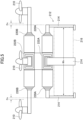
- FIG. 5 is a side view for illustrating an unmanned aerial vehicle according to a second embodiment of the present invention.
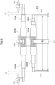
- FIG. 6 is a side view for illustrating a state in which arms of the unmanned aerial vehicle illustrated in FIG. 5 are extended.
- a plurality of vertical members 214 are each held by a corresponding one of first arms 220A.
- the first arms 220A extend in the horizontal direction and are extendable and contractible.
- a first actuator 222A is configured to extend and contract the first arms 220A.
- the plurality of vertical members 214 can be changed so that a maximum inscribed rectangle thereamong is formed into a similar shape or a non-similar shape.
- a plurality of rotary wings 210 are each held by a corresponding one of second arms 220B.
- the second arms 220B extend in the horizontal direction and are extendable and contractible.
- a second actuator 222B is configured to extend and contract the second arms 220B.
- the second group of arms 220B each vertically overlap with a corresponding one of the first group of arms 220A and extend in the same direction.
- the plurality of rotary wings 210 are arranged on an outer side of a shape of the package carrier 212 (vertical members 214) by a distance D A , D B . With this, the downward airstream of the rotary wings 210 is prevented from hitting the package 216.
- a size of the distance D A , D B is proportional to a size (width W A , W B ) of the shape of the package carrier 212. For example, when the width W B of the large package 216 illustrated in FIG. 6 is n times larger than the width W A of the small package 216 illustrated in FIG. 5 , the distance D B may be n times larger than the distance D A . With regard to other contents, the contents described in the first embodiment are applied.
- FIG. 7 is a plan view for illustrating an unmanned aerial vehicle according to a third embodiment of the present invention.
- a plurality of vertical members 314 are each held by a corresponding one of first arms 320A.
- the first arms 320A extend in the horizontal direction and are extendable and contractible.
- the first arms 320A are moved by a first actuator 322A.
- the first actuator 322A is configured to extend and contract the first arms 320A.
- the plurality of vertical members 314 can be changed so that a maximum inscribed rectangle thereamong is formed into a similar shape or a non-similar shape.
- a package 316A illustrated in FIG. 7 has a square shape in plan view.
- a plurality of rotary wings 310 are each held by a corresponding one of second arms 320B.
- the second arms 320B extend in directions different from those of the first arms 320A.
- the second arms 320B are moved by a second actuator 322B.
- the second actuator 322B is configured to swing each of the second group of arms 320B at least at one position.
- the second actuator 322B is configured to swing each of the second group of arms 320B in a horizontal direction.
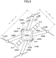
- FIG. 8 is a plan view for illustrating a state in which the arms of the unmanned aerial vehicle illustrated in FIG. 7 are extended and contracted.
- the plurality of rotary wings 310 include a first pair of rotary wings 310A which are adjacent to each other along a first direction D1.
- the plurality of rotary wings 310 include a second pair of rotary wings 310B which are adjacent to each other along a second direction D2 orthogonal to the first direction D1.
- a maximum inscribed rectangle among the plurality of vertical members 314 is formed into a rectangle elongated in the first direction D1
- a clearance C 1 of the first pair of rotary wings 310A is set larger than a clearance C 2 of the second pair of rotary wings 310B.
- a package 316B illustrated in FIG. 8 has a rectangular shape in plan view. With regard to other contents, the contents described in the first and second embodiments are applied.
- FIG. 9 is a side view for illustrating an unmanned aerial vehicle according to a fourth example not forming part of the presently claimed invention.
- the unmanned aerial vehicle includes landing gears 424, which are configured to support a vehicle body, and a package carrier 412.
- the package carrier 412 includes a plurality of vertical members 414.
- the plurality of vertical members 414 surround the package 416 in the horizontal direction to prevent falling of the package 416.
- the plurality of vertical members 414 are changeable in relative positions.
- the unmanned aerial vehicle includes a plurality of rotary wings 410.
- the plurality of rotary wings 410 are each held by a corresponding one of a plurality of arms 420.
- the plurality of arms 420 are moved by an actuator 422.
- the actuator 422 is configured to swing each of the arms 420 in a perpendicular direction.
- the swing of the arms 420 in the perpendicular direction causes the rotary wings 410 to change in the horizontal direction from a first position P 1 to a second position P 2 . That is, the plurality of rotary wings 410 are changeable in relative positions in the horizontal direction.
- the plurality of rotary wings 410 are most apart from each other, and the plurality of vertical members 414 are most apart from each other so that the package carrier 412 becomes largest.
- the plurality of rotary wings 410 are close to each other, and the plurality of vertical members 414 are close to each other so that the package carrier 412 becomes smaller.
- rotation shafts thereof are moved in parallel by a link mechanism (not shown) even when the arms 420 swing.
- the contents described in the first to third embodiments are applied.
Landscapes
- Engineering & Computer Science (AREA)
- Aviation & Aerospace Engineering (AREA)
- Mechanical Engineering (AREA)
- Remote Sensing (AREA)
- Forklifts And Lifting Vehicles (AREA)
- Manipulator (AREA)
- Toys (AREA)
Claims (11)
- Unbemanntes Luftfahrzeug, umfassend:einen Paketträger (12) einschließlich einer Vielzahl von vertikalen Elementen (14), wobei die Vielzahl von vertikalen Elementen (14) in ihren relativen Positionen in einer horizontalen Richtung veränderbar sind und ein Paket (16) in der horizontalen Richtung umgeben, um ein Herunterfallen des Pakets (16) zu verhindern;eine Vielzahl von Drehflügeln (10), deren relative Positionen in horizontaler Richtung veränderbar sind;einen Aktuator (22), der konfiguriert ist, um die relativen Positionen der Vielzahl von vertikalen Elementen (14) und die relativen Positionen der Vielzahl von Drehflügeln (10) zu verändern; undeine Vielzahl von Armen (20), die durch den Aktuator (22) beweglich sind,wobei der Paketträger (12) in horizontaler Richtung in Übereinstimmung mit den relativen Positionen der Vielzahl von vertikalen Elementen (14) in seiner Form verändert wird,wobei die Änderung der relativen Positionen der Vielzahl von Drehflügeln (10) in Verbindung mit der Form des Paketträgers (12) steht,wobei jedes der Vielzahl von vertikalen Elemente (14) von einem entsprechenden der Vielzahl von Arme (20) gehalten wird, undwobei jeder der Vielzahl von Drehflügel (10) von einem entsprechenden der Vielzahl von Arme (20) gehalten wird.
- Unbemanntes Luftfahrzeug nach Anspruch 1, wobei jeder der Vielzahl von Armen (20) konfiguriert ist, um sowohl mindestens ein entsprechendes der Vielzahl von vertikalen Elemente (14) als auch mindestens einen entsprechenden der Vielzahl von Drehflügel (10) zu halten.
- Unbemanntes Luftfahrzeug nach Anspruch 2, wobei die Vielzahl von Armen (20) sich in horizontaler Richtung erstreckt und streckbar und zusammenziehbar ist, und
wobei der Aktuator (22) konfiguriert ist, um die Vielzahl von Armen (20) zu strecken und zusammenzuziehen. - Unbemanntes Luftfahrzeug nach Anspruch 1,wobei die Vielzahl von Armen (20) einschließt:eine erste Gruppe von Armen (220A), die konfiguriert sind, um die Vielzahl von vertikalen Elementen (214) zu halten; undeine zweite Gruppe von Armen (220B), die konfiguriert sind, um die Vielzahl von Drehflügeln (210) zu halten, undwobei der Aktuator (22) einschließt:einen ersten Aktuator (222A), der konfiguriert ist, um die erste Gruppe von Armen (220A) zu bewegen; undeinen zweiten Aktuator (222B), der konfiguriert ist, um die zweite Gruppe von Armen (220B) zu bewegen.
- Unbemanntes Luftfahrzeug nach Anspruch 4, wobei die zweite Gruppe von Armen (220B) jeweils vertikal mit einem entsprechenden Arm der ersten Gruppe von Armen (220A) überlappt und sich in die gleiche Richtung erstreckt.
- Unbemanntes Luftfahrzeug nach Anspruch 4, wobei die zweite Gruppe von Armen (220B) sich in andere Richtungen als die erste Gruppe von Armen (220A) erstreckt.
- Unbemanntes Luftfahrzeug nach einem der Ansprüche 4 bis 6, wobei ein Änderungsbetrag der relativen Positionen der Vielzahl von Drehflügeln (10) proportional zu einem Änderungsbetrag der relativen Positionen der Vielzahl von vertikalen Elementen (14) ist.
- Unbemanntes Luftfahrzeug nach einem der Ansprüche 4 bis 6,wobei die erste Gruppe von Armen (320A) sich in horizontaler Richtung erstreckt und streckbar und zusammenziehbar ist, undwobei der erste Aktuator (322A) konfiguriert ist, um die erste Gruppe von Armen (320A) zu strecken und zusammenzuziehen.
- Unbemanntes Luftfahrzeug nach einem der Ansprüche 4 bis 6,wobei die zweite Gruppe von Armen (320B) sich in horizontaler Richtung erstreckt und streckbar und zusammenziehbar ist, undwobei der zweite Aktuator (322B) konfiguriert ist, um die zweite Gruppe von Armen (320B) zu strecken und zusammenzuziehen.
- Unbemanntes Luftfahrzeug nach einem der Ansprüche 4 bis 6, wobei der zweite Aktuator (322B) konfiguriert ist, um jeden der Arme der zweiten Gruppe (320B) in mindestens eine Position zu schwenken.
- Unbemanntes Luftfahrzeug nach Anspruch 10, wobei der zweite Aktuator (322B) konfiguriert ist, um jeden der Arme der zweiten Gruppe (320B) in eine horizontale Richtung zu schwenken.
Applications Claiming Priority (1)
| Application Number | Priority Date | Filing Date | Title |
|---|---|---|---|
| PCT/JP2018/048145 WO2020136803A1 (ja) | 2018-12-27 | 2018-12-27 | 無人航空機 |
Publications (3)
| Publication Number | Publication Date |
|---|---|
| EP3702279A1 EP3702279A1 (de) | 2020-09-02 |
| EP3702279A4 EP3702279A4 (de) | 2021-07-21 |
| EP3702279B1 true EP3702279B1 (de) | 2025-01-22 |
Family
ID=68314249
Family Applications (1)
| Application Number | Title | Priority Date | Filing Date |
|---|---|---|---|
| EP18934520.0A Active EP3702279B1 (de) | 2018-12-27 | 2018-12-27 | Unbemanntes flugzeug |
Country Status (5)
| Country | Link |
|---|---|
| US (1) | US11554856B2 (de) |
| EP (1) | EP3702279B1 (de) |
| JP (1) | JP6596617B1 (de) |
| CN (1) | CN111629963B (de) |
| WO (1) | WO2020136803A1 (de) |
Families Citing this family (7)
| Publication number | Priority date | Publication date | Assignee | Title |
|---|---|---|---|---|
| JP6613014B1 (ja) * | 2018-12-27 | 2019-11-27 | 楽天株式会社 | 無人航空機 |
| WO2020196733A1 (ja) * | 2019-03-28 | 2020-10-01 | 有限会社渥美不動産アンドコーポレーション | 筒型回転体を備える作業装置 |
| CN114901551A (zh) * | 2019-12-27 | 2022-08-12 | 周鹏跃 | 多旋翼飞行器 |
| JP6841544B1 (ja) * | 2020-06-08 | 2021-03-10 | 株式会社エアロネクスト | 飛行体及びこれを用いた荷物の輸送方法 |
| JP6952380B1 (ja) | 2020-08-11 | 2021-10-20 | 株式会社エアロネクスト | 移動体 |
| US12246834B2 (en) * | 2021-03-09 | 2025-03-11 | International Business Machines Corporation | Elimination of air flow interference for mid-air package transfers |
| CN115402505A (zh) * | 2022-06-20 | 2022-11-29 | 南京航空航天大学 | 采用连杆驱动机构的变直径旋翼装置 |
Family Cites Families (20)
| Publication number | Priority date | Publication date | Assignee | Title |
|---|---|---|---|---|
| DE102011116326A1 (de) * | 2011-10-18 | 2013-04-18 | Airbus Operations Gmbh | Führungsvorrichtung zum Öffnen und Schließen einer Ladeklappe eines Flugzeugs, Flugzeug mit einer solchen Führungsvorrichtung und Verfahren zum Öffnen und Schließen einer Ladeklappe eines Flugzeugs |
| WO2015109322A1 (en) * | 2014-01-20 | 2015-07-23 | Robodub Inc. | Multicopters with variable flight characteristics |
| US9550561B1 (en) | 2014-08-11 | 2017-01-24 | Amazon Technologies, Inc. | Determining center of gravity of an automated aerial vehicle and a payload |
| US9688404B1 (en) * | 2014-12-02 | 2017-06-27 | Amazon Technologies, Inc. | Stabilized airborne drop delivery |
| US20160272310A1 (en) | 2014-12-04 | 2016-09-22 | Elwha Llc | Reconfigurable unmanned aircraft system |
| US9919797B2 (en) * | 2014-12-04 | 2018-03-20 | Elwha Llc | System and method for operation and management of reconfigurable unmanned aircraft |
| US9915956B2 (en) * | 2015-01-09 | 2018-03-13 | Workhorse Group Inc. | Package delivery by means of an automated multi-copter UAS/UAV dispatched from a conventional delivery vehicle |
| CN105984583A (zh) * | 2015-02-13 | 2016-10-05 | 鸿富锦精密工业(深圳)有限公司 | 飞行器 |
| WO2017020225A1 (zh) * | 2015-08-03 | 2017-02-09 | 北京艾肯拓科技有限公司 | 无人直升飞机 |
| US10040370B2 (en) * | 2015-09-19 | 2018-08-07 | Ningbo Wise Digital Technology Co., Ltd | Container comprising a battery, transportation system comprising the same and method thereof |
| JP6536996B2 (ja) | 2016-04-26 | 2019-07-03 | 株式会社プロドローン | 鉛直投下装置 |
| CN109071015B (zh) * | 2016-04-29 | 2021-11-30 | 美国联合包裹服务公司 | 无人机拾取及递送系统 |
| KR101852844B1 (ko) * | 2016-12-27 | 2018-04-27 | 한국항공대학교산학협력단 | 무인 항공기용 고정 장치 및 무인 항공기 |
| JP2018144732A (ja) * | 2017-03-08 | 2018-09-20 | 株式会社Soken | 飛行装置 |
| CN207670664U (zh) * | 2017-11-22 | 2018-07-31 | 昊翔电能运动科技(昆山)有限公司 | 放牧旋翼无人机 |
| CN108248849A (zh) * | 2017-12-22 | 2018-07-06 | 成都才智圣有科技有限责任公司 | 一种改进的双层旋翼无人机 |
| CN108528729B (zh) * | 2018-04-16 | 2020-10-20 | 山东正夏自动化设备有限公司 | 一种物流运输用智能无人机 |
| CN208102337U (zh) * | 2018-05-03 | 2018-11-16 | 成都云翅科技有限公司 | 一种可伸缩的无人机旋翼支撑架结构 |
| US11174027B2 (en) * | 2018-07-27 | 2021-11-16 | The Boeing Company | Vehicle docking systems, payload transfer systems, and related methods |
| WO2020100820A1 (ja) | 2018-11-16 | 2020-05-22 | 有限会社渥美不動産アンドコーポレーション | 飛行体および飛行体制御システム |
-
2018
- 2018-12-27 EP EP18934520.0A patent/EP3702279B1/de active Active
- 2018-12-27 JP JP2019540672A patent/JP6596617B1/ja active Active
- 2018-12-27 WO PCT/JP2018/048145 patent/WO2020136803A1/ja not_active Ceased
- 2018-12-27 US US16/759,353 patent/US11554856B2/en active Active
- 2018-12-27 CN CN201880073803.6A patent/CN111629963B/zh active Active
Also Published As
| Publication number | Publication date |
|---|---|
| US20210214075A1 (en) | 2021-07-15 |
| JPWO2020136803A1 (ja) | 2021-02-15 |
| CN111629963A (zh) | 2020-09-04 |
| JP6596617B1 (ja) | 2019-10-23 |
| US11554856B2 (en) | 2023-01-17 |
| CN111629963B (zh) | 2023-10-17 |
| EP3702279A4 (de) | 2021-07-21 |
| EP3702279A1 (de) | 2020-09-02 |
| WO2020136803A1 (ja) | 2020-07-02 |
Similar Documents
| Publication | Publication Date | Title |
|---|---|---|
| EP3702279B1 (de) | Unbemanntes flugzeug | |
| EP3765360B1 (de) | Klemmpropellermontage | |
| CN112638769B (zh) | 无人飞行器的外部容纳装置 | |
| US10196143B2 (en) | System and method for modular unmanned aerial system | |
| EP3797070B1 (de) | Konzentrisch montierte propellerblätter für schleppverminderung | |
| US10189565B2 (en) | Modular unmanned aerial system with multi-mode propulsion | |
| CN114560088B (zh) | 飞行器、货物到达方法、系统、程序 | |
| JP7390054B2 (ja) | 移動体 | |
| CN112105555B (zh) | 用于机架的机械接合器和具有易碎机架结构的无人飞行器 | |
| WO2017204998A3 (en) | Unmanned aerial vehicle pick-up and delivery systems | |
| EP2506109B1 (de) | Flugwegsteuersystem für ein Flugzeug | |
| US20210221499A1 (en) | Unmanned aerial vehicle | |
| US20200055600A1 (en) | Payload release apparatus | |
| JP2010168034A (ja) | ダクト付きファンuav制御の代替方法 | |
| US12091173B2 (en) | UAV with distributed propulsion and blown control surfaces | |
| KR101852844B1 (ko) | 무인 항공기용 고정 장치 및 무인 항공기 | |
| WO2023113908A1 (en) | Uav with augmented lift rotors | |
| CN207902754U (zh) | 无人驾驶飞行载物装置 | |
| CN114072334B (zh) | 一种承载装置 | |
| WO2023026338A1 (ja) | 飛行体 |
Legal Events
| Date | Code | Title | Description |
|---|---|---|---|
| STAA | Information on the status of an ep patent application or granted ep patent |
Free format text: STATUS: UNKNOWN |
|
| STAA | Information on the status of an ep patent application or granted ep patent |
Free format text: STATUS: THE INTERNATIONAL PUBLICATION HAS BEEN MADE |
|
| PUAI | Public reference made under article 153(3) epc to a published international application that has entered the european phase |
Free format text: ORIGINAL CODE: 0009012 |
|
| STAA | Information on the status of an ep patent application or granted ep patent |
Free format text: STATUS: REQUEST FOR EXAMINATION WAS MADE |
|
| 17P | Request for examination filed |
Effective date: 20200330 |
|
| AK | Designated contracting states |
Kind code of ref document: A1 Designated state(s): AL AT BE BG CH CY CZ DE DK EE ES FI FR GB GR HR HU IE IS IT LI LT LU LV MC MK MT NL NO PL PT RO RS SE SI SK SM TR |
|
| AX | Request for extension of the european patent |
Extension state: BA ME |
|
| A4 | Supplementary search report drawn up and despatched |
Effective date: 20210617 |
|
| RIC1 | Information provided on ipc code assigned before grant |
Ipc: B64C 39/02 20060101AFI20210611BHEP Ipc: B64D 1/08 20060101ALI20210611BHEP Ipc: B64C 27/20 20060101ALI20210611BHEP Ipc: B64C 39/00 20060101ALI20210611BHEP |
|
| RAP3 | Party data changed (applicant data changed or rights of an application transferred) |
Owner name: RAKUTEN GROUP, INC. |
|
| DAV | Request for validation of the european patent (deleted) | ||
| DAX | Request for extension of the european patent (deleted) | ||
| STAA | Information on the status of an ep patent application or granted ep patent |
Free format text: STATUS: EXAMINATION IS IN PROGRESS |
|
| 17Q | First examination report despatched |
Effective date: 20230313 |
|
| REG | Reference to a national code |
Ref country code: DE Ref legal event code: R079 Free format text: PREVIOUS MAIN CLASS: B64C0039020000 Ipc: B64U0010140000 Ref document number: 602018078783 Country of ref document: DE |
|
| GRAP | Despatch of communication of intention to grant a patent |
Free format text: ORIGINAL CODE: EPIDOSNIGR1 |
|
| STAA | Information on the status of an ep patent application or granted ep patent |
Free format text: STATUS: GRANT OF PATENT IS INTENDED |
|
| RIC1 | Information provided on ipc code assigned before grant |
Ipc: B64U 101/64 20230101ALI20240812BHEP Ipc: B64U 30/296 20230101ALI20240812BHEP Ipc: B64U 10/14 20230101AFI20240812BHEP |
|
| INTG | Intention to grant announced |
Effective date: 20240905 |
|
| GRAS | Grant fee paid |
Free format text: ORIGINAL CODE: EPIDOSNIGR3 |
|
| GRAA | (expected) grant |
Free format text: ORIGINAL CODE: 0009210 |
|
| STAA | Information on the status of an ep patent application or granted ep patent |
Free format text: STATUS: THE PATENT HAS BEEN GRANTED |
|
| AK | Designated contracting states |
Kind code of ref document: B1 Designated state(s): AL AT BE BG CH CY CZ DE DK EE ES FI FR GB GR HR HU IE IS IT LI LT LU LV MC MK MT NL NO PL PT RO RS SE SI SK SM TR |
|
| REG | Reference to a national code |
Ref country code: GB Ref legal event code: FG4D |
|
| REG | Reference to a national code |
Ref country code: CH Ref legal event code: EP |
|
| REG | Reference to a national code |
Ref country code: IE Ref legal event code: FG4D |
|
| REG | Reference to a national code |
Ref country code: DE Ref legal event code: R096 Ref document number: 602018078783 Country of ref document: DE |
|
| REG | Reference to a national code |
Ref country code: NL Ref legal event code: MP Effective date: 20250122 |
|
| PG25 | Lapsed in a contracting state [announced via postgrant information from national office to epo] |
Ref country code: NL Free format text: LAPSE BECAUSE OF FAILURE TO SUBMIT A TRANSLATION OF THE DESCRIPTION OR TO PAY THE FEE WITHIN THE PRESCRIBED TIME-LIMIT Effective date: 20250122 |
|
| PG25 | Lapsed in a contracting state [announced via postgrant information from national office to epo] |
Ref country code: RS Free format text: LAPSE BECAUSE OF FAILURE TO SUBMIT A TRANSLATION OF THE DESCRIPTION OR TO PAY THE FEE WITHIN THE PRESCRIBED TIME-LIMIT Effective date: 20250422 |
|
| PG25 | Lapsed in a contracting state [announced via postgrant information from national office to epo] |
Ref country code: FI Free format text: LAPSE BECAUSE OF FAILURE TO SUBMIT A TRANSLATION OF THE DESCRIPTION OR TO PAY THE FEE WITHIN THE PRESCRIBED TIME-LIMIT Effective date: 20250122 |
|
| PG25 | Lapsed in a contracting state [announced via postgrant information from national office to epo] |
Ref country code: PL Free format text: LAPSE BECAUSE OF FAILURE TO SUBMIT A TRANSLATION OF THE DESCRIPTION OR TO PAY THE FEE WITHIN THE PRESCRIBED TIME-LIMIT Effective date: 20250122 |
|
| PG25 | Lapsed in a contracting state [announced via postgrant information from national office to epo] |
Ref country code: ES Free format text: LAPSE BECAUSE OF FAILURE TO SUBMIT A TRANSLATION OF THE DESCRIPTION OR TO PAY THE FEE WITHIN THE PRESCRIBED TIME-LIMIT Effective date: 20250122 |
|
| REG | Reference to a national code |
Ref country code: LT Ref legal event code: MG9D |
|
| PG25 | Lapsed in a contracting state [announced via postgrant information from national office to epo] |
Ref country code: IS Free format text: LAPSE BECAUSE OF FAILURE TO SUBMIT A TRANSLATION OF THE DESCRIPTION OR TO PAY THE FEE WITHIN THE PRESCRIBED TIME-LIMIT Effective date: 20250522 Ref country code: NO Free format text: LAPSE BECAUSE OF FAILURE TO SUBMIT A TRANSLATION OF THE DESCRIPTION OR TO PAY THE FEE WITHIN THE PRESCRIBED TIME-LIMIT Effective date: 20250422 |
|
| REG | Reference to a national code |
Ref country code: AT Ref legal event code: MK05 Ref document number: 1761317 Country of ref document: AT Kind code of ref document: T Effective date: 20250122 |
|
| PG25 | Lapsed in a contracting state [announced via postgrant information from national office to epo] |
Ref country code: HR Free format text: LAPSE BECAUSE OF FAILURE TO SUBMIT A TRANSLATION OF THE DESCRIPTION OR TO PAY THE FEE WITHIN THE PRESCRIBED TIME-LIMIT Effective date: 20250122 |
|
| PG25 | Lapsed in a contracting state [announced via postgrant information from national office to epo] |
Ref country code: LV Free format text: LAPSE BECAUSE OF FAILURE TO SUBMIT A TRANSLATION OF THE DESCRIPTION OR TO PAY THE FEE WITHIN THE PRESCRIBED TIME-LIMIT Effective date: 20250122 Ref country code: PT Free format text: LAPSE BECAUSE OF FAILURE TO SUBMIT A TRANSLATION OF THE DESCRIPTION OR TO PAY THE FEE WITHIN THE PRESCRIBED TIME-LIMIT Effective date: 20250522 |
|
| PG25 | Lapsed in a contracting state [announced via postgrant information from national office to epo] |
Ref country code: BG Free format text: LAPSE BECAUSE OF FAILURE TO SUBMIT A TRANSLATION OF THE DESCRIPTION OR TO PAY THE FEE WITHIN THE PRESCRIBED TIME-LIMIT Effective date: 20250122 Ref country code: GR Free format text: LAPSE BECAUSE OF FAILURE TO SUBMIT A TRANSLATION OF THE DESCRIPTION OR TO PAY THE FEE WITHIN THE PRESCRIBED TIME-LIMIT Effective date: 20250423 |
|
| PG25 | Lapsed in a contracting state [announced via postgrant information from national office to epo] |
Ref country code: AT Free format text: LAPSE BECAUSE OF FAILURE TO SUBMIT A TRANSLATION OF THE DESCRIPTION OR TO PAY THE FEE WITHIN THE PRESCRIBED TIME-LIMIT Effective date: 20250122 |
|
| PG25 | Lapsed in a contracting state [announced via postgrant information from national office to epo] |
Ref country code: SE Free format text: LAPSE BECAUSE OF FAILURE TO SUBMIT A TRANSLATION OF THE DESCRIPTION OR TO PAY THE FEE WITHIN THE PRESCRIBED TIME-LIMIT Effective date: 20250122 |
|
| PG25 | Lapsed in a contracting state [announced via postgrant information from national office to epo] |
Ref country code: SM Free format text: LAPSE BECAUSE OF FAILURE TO SUBMIT A TRANSLATION OF THE DESCRIPTION OR TO PAY THE FEE WITHIN THE PRESCRIBED TIME-LIMIT Effective date: 20250122 |
|
| PG25 | Lapsed in a contracting state [announced via postgrant information from national office to epo] |
Ref country code: DK Free format text: LAPSE BECAUSE OF FAILURE TO SUBMIT A TRANSLATION OF THE DESCRIPTION OR TO PAY THE FEE WITHIN THE PRESCRIBED TIME-LIMIT Effective date: 20250122 |
|
| PG25 | Lapsed in a contracting state [announced via postgrant information from national office to epo] |
Ref country code: IT Free format text: LAPSE BECAUSE OF FAILURE TO SUBMIT A TRANSLATION OF THE DESCRIPTION OR TO PAY THE FEE WITHIN THE PRESCRIBED TIME-LIMIT Effective date: 20250122 |
|
| PG25 | Lapsed in a contracting state [announced via postgrant information from national office to epo] |
Ref country code: CZ Free format text: LAPSE BECAUSE OF FAILURE TO SUBMIT A TRANSLATION OF THE DESCRIPTION OR TO PAY THE FEE WITHIN THE PRESCRIBED TIME-LIMIT Effective date: 20250122 Ref country code: EE Free format text: LAPSE BECAUSE OF FAILURE TO SUBMIT A TRANSLATION OF THE DESCRIPTION OR TO PAY THE FEE WITHIN THE PRESCRIBED TIME-LIMIT Effective date: 20250122 |
|
| REG | Reference to a national code |
Ref country code: DE Ref legal event code: R097 Ref document number: 602018078783 Country of ref document: DE |
|
| PG25 | Lapsed in a contracting state [announced via postgrant information from national office to epo] |
Ref country code: RO Free format text: LAPSE BECAUSE OF FAILURE TO SUBMIT A TRANSLATION OF THE DESCRIPTION OR TO PAY THE FEE WITHIN THE PRESCRIBED TIME-LIMIT Effective date: 20250122 |
|
| PG25 | Lapsed in a contracting state [announced via postgrant information from national office to epo] |
Ref country code: SK Free format text: LAPSE BECAUSE OF FAILURE TO SUBMIT A TRANSLATION OF THE DESCRIPTION OR TO PAY THE FEE WITHIN THE PRESCRIBED TIME-LIMIT Effective date: 20250122 |
|
| PLBE | No opposition filed within time limit |
Free format text: ORIGINAL CODE: 0009261 |
|
| STAA | Information on the status of an ep patent application or granted ep patent |
Free format text: STATUS: NO OPPOSITION FILED WITHIN TIME LIMIT |
|
| 26N | No opposition filed |
Effective date: 20251023 |
|
| PGFP | Annual fee paid to national office [announced via postgrant information from national office to epo] |
Ref country code: DE Payment date: 20251126 Year of fee payment: 8 |
|
| PGFP | Annual fee paid to national office [announced via postgrant information from national office to epo] |
Ref country code: GB Payment date: 20251120 Year of fee payment: 8 |
|
| PGFP | Annual fee paid to national office [announced via postgrant information from national office to epo] |
Ref country code: FR Payment date: 20251120 Year of fee payment: 8 |