EP3765360B1 - Klemmpropellermontage - Google Patents
Klemmpropellermontage Download PDFInfo
- Publication number
- EP3765360B1 EP3765360B1 EP19792118.2A EP19792118A EP3765360B1 EP 3765360 B1 EP3765360 B1 EP 3765360B1 EP 19792118 A EP19792118 A EP 19792118A EP 3765360 B1 EP3765360 B1 EP 3765360B1
- Authority
- EP
- European Patent Office
- Prior art keywords
- clip
- aerial vehicle
- base mount
- propeller blades
- propulsion
- Prior art date
- Legal status (The legal status is an assumption and is not a legal conclusion. Google has not performed a legal analysis and makes no representation as to the accuracy of the status listed.)
- Active
Links
Images


Classifications
-
- B—PERFORMING OPERATIONS; TRANSPORTING
- B64—AIRCRAFT; AVIATION; COSMONAUTICS
- B64C—AEROPLANES; HELICOPTERS
- B64C11/00—Propellers, e.g. of ducted type; Features common to propellers and rotors for rotorcraft
- B64C11/02—Hub construction
- B64C11/04—Blade mountings
-
- B—PERFORMING OPERATIONS; TRANSPORTING
- B64—AIRCRAFT; AVIATION; COSMONAUTICS
- B64C—AEROPLANES; HELICOPTERS
- B64C11/00—Propellers, e.g. of ducted type; Features common to propellers and rotors for rotorcraft
- B64C11/02—Hub construction
- B64C11/04—Blade mountings
- B64C11/08—Blade mountings for non-adjustable blades
-
- B—PERFORMING OPERATIONS; TRANSPORTING
- B64—AIRCRAFT; AVIATION; COSMONAUTICS
- B64C—AEROPLANES; HELICOPTERS
- B64C11/00—Propellers, e.g. of ducted type; Features common to propellers and rotors for rotorcraft
- B64C11/16—Blades
- B64C11/20—Constructional features
- B64C11/28—Collapsible or foldable blades
-
- B—PERFORMING OPERATIONS; TRANSPORTING
- B64—AIRCRAFT; AVIATION; COSMONAUTICS
- B64C—AEROPLANES; HELICOPTERS
- B64C27/00—Rotorcraft; Rotors peculiar thereto
- B64C27/22—Compound rotorcraft, i.e. aircraft using in flight the features of both aeroplane and rotorcraft
- B64C27/26—Compound rotorcraft, i.e. aircraft using in flight the features of both aeroplane and rotorcraft characterised by provision of fixed wings
-
- B—PERFORMING OPERATIONS; TRANSPORTING
- B64—AIRCRAFT; AVIATION; COSMONAUTICS
- B64C—AEROPLANES; HELICOPTERS
- B64C29/00—Aircraft capable of landing or taking-off vertically, e.g. vertical take-off and landing [VTOL] aircraft
- B64C29/0008—Aircraft capable of landing or taking-off vertically, e.g. vertical take-off and landing [VTOL] aircraft having its flight directional axis horizontal when grounded
- B64C29/0016—Aircraft capable of landing or taking-off vertically, e.g. vertical take-off and landing [VTOL] aircraft having its flight directional axis horizontal when grounded the lift during taking-off being created by free or ducted propellers or by blowers
- B64C29/0025—Aircraft capable of landing or taking-off vertically, e.g. vertical take-off and landing [VTOL] aircraft having its flight directional axis horizontal when grounded the lift during taking-off being created by free or ducted propellers or by blowers the propellers being fixed relative to the fuselage
-
- B—PERFORMING OPERATIONS; TRANSPORTING
- B64—AIRCRAFT; AVIATION; COSMONAUTICS
- B64C—AEROPLANES; HELICOPTERS
- B64C39/00—Aircraft not otherwise provided for
- B64C39/04—Aircraft not otherwise provided for having multiple fuselages or tail booms
-
- B—PERFORMING OPERATIONS; TRANSPORTING
- B64—AIRCRAFT; AVIATION; COSMONAUTICS
- B64D—EQUIPMENT FOR FITTING IN OR TO AIRCRAFT; FLIGHT SUITS; PARACHUTES; ARRANGEMENT OR MOUNTING OF POWER PLANTS OR PROPULSION TRANSMISSIONS IN AIRCRAFT
- B64D31/00—Power plant control systems; Arrangement of power plant control systems in aircraft
- B64D31/02—Initiating means
- B64D31/06—Initiating means actuated automatically
-
- B—PERFORMING OPERATIONS; TRANSPORTING
- B64—AIRCRAFT; AVIATION; COSMONAUTICS
- B64U—UNMANNED AERIAL VEHICLES [UAV]; EQUIPMENT THEREFOR
- B64U30/00—Means for producing lift; Empennages; Arrangements thereof
- B64U30/20—Rotors; Rotor supports
-
- B—PERFORMING OPERATIONS; TRANSPORTING
- B64—AIRCRAFT; AVIATION; COSMONAUTICS
- B64U—UNMANNED AERIAL VEHICLES [UAV]; EQUIPMENT THEREFOR
- B64U30/00—Means for producing lift; Empennages; Arrangements thereof
- B64U30/20—Rotors; Rotor supports
- B64U30/29—Constructional aspects of rotors or rotor supports; Arrangements thereof
- B64U30/293—Foldable or collapsible rotors or rotor supports
-
- B—PERFORMING OPERATIONS; TRANSPORTING
- B64—AIRCRAFT; AVIATION; COSMONAUTICS
- B64U—UNMANNED AERIAL VEHICLES [UAV]; EQUIPMENT THEREFOR
- B64U50/00—Propulsion; Power supply
- B64U50/10—Propulsion
- B64U50/13—Propulsion using external fans or propellers
-
- B—PERFORMING OPERATIONS; TRANSPORTING
- B64—AIRCRAFT; AVIATION; COSMONAUTICS
- B64U—UNMANNED AERIAL VEHICLES [UAV]; EQUIPMENT THEREFOR
- B64U50/00—Propulsion; Power supply
- B64U50/10—Propulsion
- B64U50/18—Thrust vectoring
-
- G—PHYSICS
- G05—CONTROLLING; REGULATING
- G05D—SYSTEMS FOR CONTROLLING OR REGULATING NON-ELECTRIC VARIABLES
- G05D1/00—Control of position, course, altitude or attitude of land, water, air or space vehicles, e.g. using automatic pilots
- G05D1/04—Control of altitude or depth
- G05D1/042—Control of altitude or depth specially adapted for aircraft
-
- G—PHYSICS
- G05—CONTROLLING; REGULATING
- G05D—SYSTEMS FOR CONTROLLING OR REGULATING NON-ELECTRIC VARIABLES
- G05D1/00—Control of position, course, altitude or attitude of land, water, air or space vehicles, e.g. using automatic pilots
- G05D1/08—Control of attitude, i.e. control of roll, pitch, or yaw
- G05D1/0808—Control of attitude, i.e. control of roll, pitch, or yaw specially adapted for aircraft
-
- B—PERFORMING OPERATIONS; TRANSPORTING
- B64—AIRCRAFT; AVIATION; COSMONAUTICS
- B64U—UNMANNED AERIAL VEHICLES [UAV]; EQUIPMENT THEREFOR
- B64U10/00—Type of UAV
- B64U10/20—Vertical take-off and landing [VTOL] aircraft
-
- B—PERFORMING OPERATIONS; TRANSPORTING
- B64—AIRCRAFT; AVIATION; COSMONAUTICS
- B64U—UNMANNED AERIAL VEHICLES [UAV]; EQUIPMENT THEREFOR
- B64U30/00—Means for producing lift; Empennages; Arrangements thereof
- B64U30/40—Empennages, e.g. V-tails
-
- B—PERFORMING OPERATIONS; TRANSPORTING
- B64—AIRCRAFT; AVIATION; COSMONAUTICS
- B64U—UNMANNED AERIAL VEHICLES [UAV]; EQUIPMENT THEREFOR
- B64U50/00—Propulsion; Power supply
- B64U50/10—Propulsion
- B64U50/13—Propulsion using external fans or propellers
- B64U50/14—Propulsion using external fans or propellers ducted or shrouded
-
- F—MECHANICAL ENGINEERING; LIGHTING; HEATING; WEAPONS; BLASTING
- F16—ENGINEERING ELEMENTS AND UNITS; GENERAL MEASURES FOR PRODUCING AND MAINTAINING EFFECTIVE FUNCTIONING OF MACHINES OR INSTALLATIONS; THERMAL INSULATION IN GENERAL
- F16B—DEVICES FOR FASTENING OR SECURING CONSTRUCTIONAL ELEMENTS OR MACHINE PARTS TOGETHER, e.g. NAILS, BOLTS, CIRCLIPS, CLAMPS, CLIPS OR WEDGES; JOINTS OR JOINTING
- F16B21/00—Means for preventing relative axial movement of a pin, spigot, shaft or the like and a member surrounding it; Stud-and-socket releasable fastenings
- F16B21/02—Releasable fastening devices locking by rotation
- F16B21/04—Releasable fastening devices locking by rotation with bayonet catch
-
- F—MECHANICAL ENGINEERING; LIGHTING; HEATING; WEAPONS; BLASTING
- F16—ENGINEERING ELEMENTS AND UNITS; GENERAL MEASURES FOR PRODUCING AND MAINTAINING EFFECTIVE FUNCTIONING OF MACHINES OR INSTALLATIONS; THERMAL INSULATION IN GENERAL
- F16C—SHAFTS; FLEXIBLE SHAFTS; ELEMENTS OR CRANKSHAFT MECHANISMS; ROTARY BODIES OTHER THAN GEARING ELEMENTS; BEARINGS
- F16C2226/00—Joining parts; Fastening; Assembling or mounting parts
- F16C2226/50—Positive connections
- F16C2226/70—Positive connections with complementary interlocking parts
- F16C2226/72—Positive connections with complementary interlocking parts with bayonet joints, i.e. parts are rotated to create positive interlock
-
- F—MECHANICAL ENGINEERING; LIGHTING; HEATING; WEAPONS; BLASTING
- F16—ENGINEERING ELEMENTS AND UNITS; GENERAL MEASURES FOR PRODUCING AND MAINTAINING EFFECTIVE FUNCTIONING OF MACHINES OR INSTALLATIONS; THERMAL INSULATION IN GENERAL
- F16C—SHAFTS; FLEXIBLE SHAFTS; ELEMENTS OR CRANKSHAFT MECHANISMS; ROTARY BODIES OTHER THAN GEARING ELEMENTS; BEARINGS
- F16C2226/00—Joining parts; Fastening; Assembling or mounting parts
- F16C2226/50—Positive connections
- F16C2226/70—Positive connections with complementary interlocking parts
- F16C2226/74—Positive connections with complementary interlocking parts with snap-fit, e.g. by clips
-
- F—MECHANICAL ENGINEERING; LIGHTING; HEATING; WEAPONS; BLASTING
- F16—ENGINEERING ELEMENTS AND UNITS; GENERAL MEASURES FOR PRODUCING AND MAINTAINING EFFECTIVE FUNCTIONING OF MACHINES OR INSTALLATIONS; THERMAL INSULATION IN GENERAL
- F16C—SHAFTS; FLEXIBLE SHAFTS; ELEMENTS OR CRANKSHAFT MECHANISMS; ROTARY BODIES OTHER THAN GEARING ELEMENTS; BEARINGS
- F16C2326/00—Articles relating to transporting
- F16C2326/43—Aeroplanes; Helicopters
Definitions
- This disclosure relates generally to propeller blade mounts, and in particular but not exclusively, relates to propeller blade mounts for unmanned aerial vehicles.
- An unmanned vehicle which may also be referred to as an autonomous vehicle, is a vehicle capable of travel without a physically-present human operator.
- An unmanned vehicle may operate in a remote-control mode, in an autonomous mode, or in a partially autonomous mode.
- an unmanned vehicle When an unmanned vehicle operates in a remote-control mode, a pilot or driver that is at a remote location can control the unmanned vehicle via commands that are sent to the unmanned vehicle via a wireless link.
- the unmanned vehicle When the unmanned vehicle operates in autonomous mode, the unmanned vehicle typically moves based on pre-programmed navigation waypoints, dynamic automation systems, or a combination of these. Further, some unmanned vehicles can operate in both a remote-control mode and an autonomous mode, and in some instances may do so simultaneously. For instance, a remote pilot or driver may wish to leave navigation to an autonomous system while manually performing another task, such as operating a mechanical system for picking up objects, as an example.
- UAVs Unmanned aerial vehicles
- PCT patent application publication no. WO 2018/039994 A1 presents a driving device used for being connected to a propeller, wherein bars of a blade seat protrudes into inlets through a locking portion. During assembly, the propeller is rotated in the assembly direction so that the bars are set under a stepped block of the latching portion. Each bar is clamped against the propeller thanks to an elastic member.
- United States patent application publication no. US 2016/001879 A1 presents a folding propeller system for safe packing and shipping, and easy deployment.
- United States patent application publication no. US 2017/106978 A1 presents a tote package for carrying a load external to a UAV.
- Chinese utility model publication no. CN 206 569 266 U presents an aircraft and screw fast dismantle device, quick detach formula screw and screw base subassembly thereof.
- Chinese utility model publication no. CN 206 939 054 U presents a screw oar seat and unmanned aerial vehicle.
- a propulsion unit is defined in claim 1.
- an aerial vehicle is defined in claim 7.
- Preferred embodiments are defined in the dependent claims.
- Examples not covered by the claims disclosed herein describe mechanical structures and techniques for pivot mounting propeller blades to a motor rotor that enable passive folding of the propeller blades from a deployed position when in use to a stowed position when idle.
- the stowed position provides reduced drag during forward flight.
- the folding of the propeller blades to the stowed position is passively achieved by wind resistance while pivoting back to the deployed position is achieved via centrifugal force due to offset positioning of pivot mounts from the central rotational axis of the motor rotor.
- propeller blade mounts are applicable for use in a variety of vehicle applications, the described techniques are particularly useful in applications having separate propulsion units for horizontal and vertical propulsion where the vertical takeoff and landing propulsion is idle during horizontal cruise.
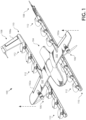
- FIGs. 1 and 2 illustrate an aerial vehicle 100, in accordance with an embodiment of the disclosure.
- the illustrated embodiment of aerial vehicle 100 is a vertical takeoff and landing (VTOL) unmanned aerial vehicle (UAV) that includes separate propulsion units 106 and 112 for providing horizontal and vertical propulsion, respectively.
- Aerial vehicle 100 is a fixed-wing aerial vehicle, which as the name implies, has a wing assembly 102 that can generate lift based on the wing shape and the vehicle's forward airspeed when propelled horizontally by propulsion units 106.
- FIG. 1 is a perspective view illustration of aerial vehicle 100 operating during a vertical takeoff or landing with the propeller blades of vertical propulsion units 112 deployed to provide vertical propulsion.
- FIG. 2 is a plan view illustration of aerial vehicle 100 operating in a horizontal cruise mode with the propeller blades of vertical propulsion units 112 idle (i.e., not spinning) and stowed to reduce a drag profile during forward motion.
- the propeller blades of vertical propulsion units 112 are stowed and passively align for reduced drag due to wind resistance resulting from the forward motion of aerial vehicle 100.
- the propeller blades of vertical propulsion units 112 are deployed in FIG. 1 due to centrifugal forces when vertical propulsion units 112 are spinning.
- the aerial vehicle 100 has an airframe that includes a fuselage 104 and wing assembly 102.
- the fuselage 104 is modular and includes a battery module, an avionics module, and a mission payload module. These modules may be detachable from each other and mechanically securable to each other to contiguously form at least a portion of the fuselage or main body.
- the battery module includes a cavity for housing one or more batteries for powering aerial vehicle 100.
- the avionics module houses flight control circuitry of aerial vehicle 100, which may include a processor and memory, communication electronics and antennas (e.g., cellular transceiver, wifi transceiver, etc.), and various sensors (e.g., global positioning sensor, an inertial measurement unit (IMU), a magnetic compass, etc.).
- the mission payload module houses equipment associated with a mission of aerial vehicle 100.
- the mission payload module may include a payload actuator for holding and releasing an externally attached payload.
- the mission payload module may include a camera/sensor equipment holder for carrying cameralsensor equipment (e.g., camera, lenses, radar, lidar, pollution monitoring sensors, weather monitoring sensors, etc.).
- aerial vehicle 100 includes horizontal propulsion units 106 positioned on wing assembly 102, which can each include a motor, a motor rotor with shaft, and propeller blades, for propelling aerial vehicle 100 horizontally.
- the aerial vehicle 100 further includes two boom assemblies 110 that secure to wing assembly 102.
- Vertical propulsion units 112 are mounted to boom assemblies 110.
- Vertical propulsion units 112 can each also include a motor, a motor rotor with shaft, and propeller blades, for providing vertical propulsion.
- vertical propulsion units 112 may be used during a hover mode where aerial vehicle 100 is descending (e.g., to a delivery location), ascending (e.g., following a delivery), or maintaining a constant altitude.
- Stabilizers 108 may be included with aerial vehicle 100 to control pitch and stabilize the aerial vehicle's yaw (left or right turns) during cruise.
- vertical propulsion units 112 are disabled and during hover mode horizontal propulsion units 106 are disabled.
- Vertical propulsion units 112 are merely powered low during cruise mode and/or horizontal propulsion units 106 are merely powered low during hover mode.
- aerial vehicle 100 may control the direction and/or speed of its movement by controlling its pitch, roll, yaw, and/or altitude. Thrust from horizontal propulsion units 106 is used to control air speed.
- the stabilizers 108 may include one or more rudders 108a for controlling the aerial vehicle's yaw
- wing assembly 102 may include elevators for controlling the aerial vehicle's pitch and/or ailerons 102a for controlling the aerial vehicle's roll.
- Increasing or decreasing the speed of all the propeller blades simultaneously can result in aerial vehicle 100 increasing or decreasing its altitude, respectively.
- FIGs. 1 and 2 illustrate one wing assembly 102, two boom assemblies 110, two horizontal propulsion units 106, and six vertical propulsion units 112 per boom assembly 110, it should be appreciated that other variants of aerial vehicle 100 may be implemented with more or less of these components.
- references herein to an "unmanned" aerial vehicle or UAV can apply equally to autonomous and semi-autonomous aerial vehicles.
- all functionality of the aerial vehicle is automated; e.g., pre-programmed or controlled via real-time computer functionality that responds to input from various sensors and/or pre-determined information.
- some functions of an aerial vehicle may be controlled by a human operator, while other functions are carried out autonomously.
- a UAV may be configured to allow a remote operator to take over functions that can otherwise be controlled autonomously by the UAV.
- a given type of function may be controlled remotely at one level of abstraction and performed autonomously at another level of abstraction.
- a remote operator may control high level navigation decisions for a UAV, such as specifying that the UAV should travel from one location to another (e.g., from a warehouse in a suburban area to a delivery address in a nearby city), while the UAV's navigation system autonomously controls more fine-grained navigation decisions, such as the specific route to take between the two locations, specific flight controls to achieve the route and avoid obstacles while navigating the route, and so on.
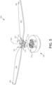
- FIGs. 3 , 4 , 5 , 6A, and 6B are different views illustrating various aspects of a subassembly 300 of a propulsion unit (e.g., a vertical propulsion unit 112) for coupling propeller blades to a motor rotor, in accordance with an embodiment of the disclosure.
- FIGs. 3 and 6A are top perspective views
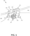
- FIG. 4 a bottom perspective view
- FIG. 5 is an exploded view of subassembly 300.
- the illustrated embodiment of subassembly 300 includes a motor rotor 305, a clip-in base mount 310, a holder base 315, a holder cap 320, pivot mounts 325, stop blocks 330, propeller blades 335, and a mechanical fastener 317.
- the illustrated embodiment of clip-in base mount 310 includes a raised alignment ring 340, cam grooves 345, and detents 350 (see FIG. 6B ).
- the illustrated embodiment of holder base 315 includes holding cams 355, a spring cavity 360, and a spring 365 (see FIG. 4 ).
- the illustrated embodiment of propeller blades 335 includes a proximal base 370, a hole 375 in proximal base 370, and a distal tip 380 (see FIGs. 3 and 5 ).
- the motor rotor 305 includes a cover plate 307 connected to a shaft 309 both of which rotate together.
- pivot mounts 325 are implemented as bearings 326 that slide through holes 375 in propeller blades 335 and mate with recesses 510 in holder cap 320.
- Bearings 326 constrain the motion of propeller blades 335 to a rotation about offset pivoting axes 505.
- Offset pivoting axes 505 are substantially parallel to, but physically offset from, a central rotational axis 306 about which motor rotor 305 turns.
- Bearings 326 extend between holder base 315 and holder cap 320 along offset pivoting axes 505. Holes 375 in proximal bases 370 slide over and fit around bearings 325.
- Bearings 326 are cylindrical bosses attached to holder base 315, which secure into recesses 510 in holder cap 320.
- Holder base 315 along with bearings 326 is fabricated of metal (e.g., aluminum) while propeller blades 335 are fabricated of plastic.
- the holder base 315 along with bearings 326 is anodized and/or coated with polytetrafluoroethylene (PTFE) to improve wear characteristics.
- PTFE polytetrafluoroethylene
- One or more of the components may be fabricated of carbon fiber reinforced polymer.
- Holder cap 320 operates not only to support the top sides of bearings 326 but also clamps propeller blades 335 between holder base 315 and holder cap 320.
- a single mechanical fastener 317 threads into a single female threaded boss on holder cap 320 along central rotational axis 306 to provide the clamping force.
- Bearings 326 may be implemented as female threaded bosses and a pair of mechanical fasteners may be threaded through holder cap 320 into the threaded bosses along offset pivoting axes 505 (e.g., see FIG. 7 ).
- the length of bearings 326 relative to the thickness of proximal bases 370 of propeller blades 335 is selected to allow propeller blades 335 to freely pivot about offset pivoting axes 505 without permitting undue slop or dihedral bending.
- stop blocks 330 that contact propeller blades 335 have curvatures that mate to the local curvatures of propeller blades 335 to distribute the forces on propeller blades 335 over a larger area.
- the contacting surfaces of stop blocks 330 are fabricated of a material that is softer than propeller blades 335 to reduce dents on or damage to propeller blades 335.
- stop blocks 330 may have a rubberized coating, a plastic coating, or otherwise.
- Stop blocks 330 are sized such that the given stop block 330 that comes to a rest in the downwind position also serves to prevent the aerodynamic surfaces (e.g., lifting surfaces, trailing edge, leading edge, etc.) of propeller blades 335 from contacting each other in the stowed position.
- FIGs. 4 and 5 illustrate stop blocks 330 integrated into holder base 315
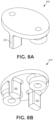
- the stop blocks may be integrated into the holder cap (e.g., see FIGs. 8A and 8B ).
- the stop blocks may be formed into the proximal bases 370 of propeller blades 335 (not illustrated).
- the illustrated embodiment of subassembly 300 is a clip-in embodiment that attaches propeller blades 335 to motor rotor 305 by hand in the field without the need of a tool.
- holder base 315 is also referred to as a clip-in rotor cap 315 since it clips onto and caps over the motor rotor 305.
- clip-in rotor cap 315 (a.k.a. holder base 315), includes holding cams 355 that mate to cam grooves 345 disposed in clip-in base mount 310. Holding cams 355 are mechanically linkages that slide in cam grooves 345.
- Each holding cam 355 is a sort of foot or L-shaped bracket that protrudes from the backside of clip-in rotor cap 315 that faces clip-in base mount 310.
- clip-in rotor cap 315 detachably clips (mates) into clip-in base mount 310 with a three part motion: (1) align holding cams 355 to cam grooves 345 and push the components together to overcome the repelling force from spring 365, (2) twist clip-in rotor cap 315 relative to clip-in base mount 310, and (3) release clip-in rotor cap 315 such that spring 365 forces holding cams 355 into detents 350.
- spring 365 is disposed within spring cavity 360 and secured in place by mechanical fastener 317 at the tight curl end of spring 365.
- Alignment ring 340 ( FIG. 6B ) extends around the perimeter of clip-in base mount 310 and provides an alignment structure and shear force retention for clip-in rotor cap 315.
- clip-in rotor cap 315 and clip-in base mount 310 are designed to provide automatic "pop off" separation in the event of a propeller blade collision with a physical object having a threshold mass.
- detents 350 have beveled stops (only abrupt 90 degree stops 351 are illustrated) and the spring rate of spring 365 selected such that a sufficient rotational force will separate clip-in rotor cap 315 along with propeller blades 335 from motor rotor 305 and clip-in base mount 310.
- the direction of rotational separation of holding cams 355 out of grooves 345 is selected to be opposite the rotational direction of motor rotor 305 during operation.
- clip-in base mount 310 is secured to motor rotor 305 with mechanical fasteners (e.g., four) through screw holes 605.
- FIG. 7 is a perspective view illustration of another subassembly 700 for coupling propeller blades 335 to a motor rotor 705.
- the subassembly 700 includes motor rotor 705, a holder base 715, a holder cap 720, pivot mounts 725, and mechanical fasteners 717 and 718.
- Subassembly 700 operates in a similar manner as subassembly 300 to secure propeller blades 335 to motor rotor 705 using pivot mounts 725 at offset pivoting axes 730 that are substantially parallel to but offset from central rotational axis 740.
- pivot mounts 725 are bearings fabricated from female threaded bosses extending from holder base 715.
- Holder cap 720 is secured over the female threaded bosses with mechanical fasteners 717 that thread through holder cap 720 into the female threaded bosses.
- motor rotor 705 is illustrated as having a hub, spoke, and rim cover plate, it should be appreciated that the cover plates of motor rotors 305 or 705 may assume this shape or otherwise.
- FIGs. 8A and 8B are perspective view illustrations of a holder cap 800.
- Holder cap 800 includes integrated stop blocks 805.
- Holder cap 800 may be used in connection with either of subassemblies 300 or 700 to replace their illustrated holder caps 320 or 720, respectively.
Landscapes
- Engineering & Computer Science (AREA)
- Aviation & Aerospace Engineering (AREA)
- Chemical & Material Sciences (AREA)
- Combustion & Propulsion (AREA)
- Mechanical Engineering (AREA)
- Remote Sensing (AREA)
- Radar, Positioning & Navigation (AREA)
- Physics & Mathematics (AREA)
- General Physics & Mathematics (AREA)
- Automation & Control Theory (AREA)
- Control Of Position, Course, Altitude, Or Attitude Of Moving Bodies (AREA)
- Structures Of Non-Positive Displacement Pumps (AREA)
- Toys (AREA)
- Shafts, Cranks, Connecting Bars, And Related Bearings (AREA)
- Sheet Holders (AREA)
Claims (8)
- Antriebseinheit (106, 112), umfassend:einen Motorrotor (305), der sich um eine zentrale Drehachse dreht; einen Einklipp-Basishalter (310), der auf dem Motorrotor angeordnet ist;eine Einklipp-Rotorkappe (315), die so geformt ist, dass sie mit dem Einklipp-Basishalter zusammenpasst und in diesen lösbar einklippt, wobei der Einklipp-Basishalter eine oder mehrere Nockennuten (345) beinhaltet und die Einklipp-Rotorkappe Haltenocken (355) beinhaltet, die mit der einen oder den mehreren Nockennuten zusammenpassen, undwobei der Einklipp-Basishalter ferner Arretierungen (350) umfasst, die in der einen oder den mehreren Nockennuten angeordnet sind, um Widerstand gegen eine Drehtrennung der Haltenocken von der einen oder den mehreren Nockennuten bereitzustellen;Propellerhalter, die an der Einklipp-Rotorkappe angebracht sind; undPropellerblätter (335), die jeweils eine proximale Basis und eine distale Spitze aufweisen, wobei die proximale Basis jedes Propellerblatts an einem entsprechenden der Propellerhalter befestigt ist.
- Antriebseinheit nach Anspruch 1,wobei die Einklipp-Rotorkappe von Hand ohne Werkzeug an dem Einklipp-Basishalter befestigbar ist; oderwobei die Einklipp-Rotorkappe ferner Folgendes beinhaltet:einen Federhohlraum (360); undeine in dem Federhohlraum angeordnete Feder (365), die eine abstoßende Kraft zwischen dem Einklipp-Basishalter und der Einklipp-Rotorkappe aufbringt, wenn die Einklipp-Rotorkappe mit dem Einklipp-Basishalter zusammengepasst ist.
- Antriebseinheit nach Anspruch 1, wobei die Arretierungen jeweils einen abgeschrägten Anschlag in der einen oder den mehreren Nockennuten umfassen.
- Antriebseinheit nach Anspruch 3, wobei eine Neigungsrichtung des abgeschrägten Anschlags zusammen mit einer Richtung der Drehtrennung der Haltenocken von der einen oder den mehreren Nuten eine Abtrennung der Einklipp-Rotorkappe und der Propellerblätter von dem Motorrotor ermöglicht, falls ein physisches Objekt einer Schwellenmasse auf ein oder mehrere der Propellerblätter trifft, wenn sich die Propellerblätter drehen.
- Antriebseinheit nach Anspruch 1, wobei der Einklipp-Basishalter ferner Folgendes umfasst:
einen erhöhten Ausrichtungsring (340), der sich zumindest teilweise um einen Umfang des Einklipp-Basishalters erstreckt. - Antriebseinheit nach Anspruch 5, wobei die eine oder die mehreren Nockennuten entlang Innenkanten des erhöhten Ausrichtungsrings angeordnet sind.
- Luftfahrzeug (100), umfassend:ein Flugwerk; undeine oder mehrere Antriebseinheiten (106, 112) nach einem der Ansprüche 1-6, die an dem Flugwerk angebracht sind, um Antrieb für das Luftfahrzeug bereitzustellen.
- Luftfahrzeug nach Anspruch 7, wobei das Luftfahrzeug ein unbemanntes Luftfahrzeug (UAV) mit Fähigkeit zu Senkrechtstart und -landung (VTOL) umfasst und die Antriebseinheiten an dem Flugwerk angebrachte horizontale Antriebseinheiten (106) zum Bereitstellen horizontalen Antriebs und an dem Flugwerk angebrachte vertikale Antriebseinheiten (112) zum Bereitstellen vertikalen Antriebs beinhalten.
Priority Applications (1)
| Application Number | Priority Date | Filing Date | Title |
|---|---|---|---|
| EP23203773.9A EP4286284A3 (de) | 2018-04-27 | 2019-04-24 | Aufklemmbare propellerbefestigung |
Applications Claiming Priority (3)
| Application Number | Priority Date | Filing Date | Title |
|---|---|---|---|
| US201862663503P | 2018-04-27 | 2018-04-27 | |
| US16/007,814 US10780975B2 (en) | 2018-04-27 | 2018-06-13 | Clip-on propeller mount |
| PCT/US2019/029007 WO2019210010A1 (en) | 2018-04-27 | 2019-04-24 | Clip-on propeller mount |
Related Child Applications (2)
| Application Number | Title | Priority Date | Filing Date |
|---|---|---|---|
| EP23203773.9A Division EP4286284A3 (de) | 2018-04-27 | 2019-04-24 | Aufklemmbare propellerbefestigung |
| EP23203773.9A Division-Into EP4286284A3 (de) | 2018-04-27 | 2019-04-24 | Aufklemmbare propellerbefestigung |
Publications (3)
| Publication Number | Publication Date |
|---|---|
| EP3765360A1 EP3765360A1 (de) | 2021-01-20 |
| EP3765360A4 EP3765360A4 (de) | 2021-12-29 |
| EP3765360B1 true EP3765360B1 (de) | 2023-11-22 |
Family
ID=68292112
Family Applications (4)
| Application Number | Title | Priority Date | Filing Date |
|---|---|---|---|
| EP19794081.0A Active EP3755624B1 (de) | 2018-04-27 | 2019-04-18 | Schubzuordnung für ein luftfahrzeug |
| EP23203773.9A Pending EP4286284A3 (de) | 2018-04-27 | 2019-04-24 | Aufklemmbare propellerbefestigung |
| EP19793603.2A Pending EP3765366A4 (de) | 2018-04-27 | 2019-04-24 | Gegenläufige propeller für luftfahrzeug |
| EP19792118.2A Active EP3765360B1 (de) | 2018-04-27 | 2019-04-24 | Klemmpropellermontage |
Family Applications Before (3)
| Application Number | Title | Priority Date | Filing Date |
|---|---|---|---|
| EP19794081.0A Active EP3755624B1 (de) | 2018-04-27 | 2019-04-18 | Schubzuordnung für ein luftfahrzeug |
| EP23203773.9A Pending EP4286284A3 (de) | 2018-04-27 | 2019-04-24 | Aufklemmbare propellerbefestigung |
| EP19793603.2A Pending EP3765366A4 (de) | 2018-04-27 | 2019-04-24 | Gegenläufige propeller für luftfahrzeug |
Country Status (6)
| Country | Link |
|---|---|
| US (2) | US11091260B2 (de) |
| EP (4) | EP3755624B1 (de) |
| CN (3) | CN112020465B (de) |
| AU (4) | AU2019260589B2 (de) |
| SG (3) | SG11202009812SA (de) |
| WO (3) | WO2019209629A1 (de) |
Families Citing this family (27)
| Publication number | Priority date | Publication date | Assignee | Title |
|---|---|---|---|---|
| US11332239B2 (en) * | 2017-07-06 | 2022-05-17 | Shanghai Autoflight Co., Ltd. | Fixed-wing VTOL aerial vehicle |
| US10387727B2 (en) | 2017-09-13 | 2019-08-20 | Wing Aviation Llc | Backup navigation system for unmanned aerial vehicles |
| US11003182B2 (en) * | 2019-01-04 | 2021-05-11 | Ford Global Technologies, Llc | Vehicle monitoring and control infrastructure |
| DE102019101903B4 (de) * | 2019-01-25 | 2024-05-16 | Volocopter Gmbh | Flugsteuerungseinheit und Verfahren zur Flug-Stabilisierung eines personen- oder lasttragenden Multikopters |
| USD903577S1 (en) * | 2019-06-17 | 2020-12-01 | Beta Air, Llc | Aircraft |
| US11505314B2 (en) * | 2019-07-22 | 2022-11-22 | Aurora Flight Sciences Corporation | Vertical takeoff and landing aircraft with tiltable rotors |
| USD903578S1 (en) * | 2019-08-28 | 2020-12-01 | Volansi, Inc | Aircraft |
| US11507115B2 (en) * | 2019-10-09 | 2022-11-22 | Wing Aviation Llc | Contingent use of commanded speed in lieu of sensed airspeed to inform flight control decisions |
| CN112849403B (zh) * | 2019-11-26 | 2023-09-29 | 上海峰飞航空科技有限公司 | 无人飞行器及其控制方法 |
| DE102020111810A1 (de) * | 2020-04-30 | 2021-11-04 | Volocopter Gmbh | Verfahren zum Betreiben eines Fluggeräts, Flugsteuerungssystem für ein Fluggerät und Fluggerät mit einem solchen |
| WO2021260730A1 (en) * | 2020-06-26 | 2021-12-30 | Ucal Fuel Systems Limited | Multipurpose and long endurance hybrid unmanned aerial vehicle |
| CN112478125B (zh) * | 2020-12-11 | 2022-04-29 | 西安电子科技大学 | 一种具备自主飞行能力的飞行阵列系统 |
| USD988926S1 (en) * | 2021-01-14 | 2023-06-13 | Wing Aviation Llc | Unmanned aerial vehicle |
| US11945597B2 (en) | 2021-01-25 | 2024-04-02 | Archer Aviation, Inc. | Systems and methods for control allocation for electric vertical take-off and landing aircraft |
| JP7345226B2 (ja) * | 2021-02-25 | 2023-09-15 | テトラ・アビエーション株式会社 | 航空機 |
| US12344390B2 (en) * | 2021-03-10 | 2025-07-01 | Textron Innovations Inc. | Method of adjusting directional movement ability in a multi-rotor aircraft |
| CN112817338B (zh) * | 2021-04-16 | 2021-07-09 | 北京三快在线科技有限公司 | 无人机的控制方法、装置、存储介质及电子设备 |
| US11208206B1 (en) * | 2021-05-17 | 2021-12-28 | Beta Air, Llc | Aircraft for fixed pitch lift |
| CN215098252U (zh) * | 2021-05-27 | 2021-12-10 | 上海峰飞航空科技有限公司 | 一种水陆两用载货无人机 |
| US20220402603A1 (en) * | 2021-06-22 | 2022-12-22 | Kitty Hawk Corporation | Vehicle with tractor tiltrotors and pusher tiltrotors |
| US11420756B1 (en) | 2021-07-01 | 2022-08-23 | Beta Air, Llc | Systems and methods for fault detection and control in an electric aircraft |
| US11827346B1 (en) * | 2022-05-04 | 2023-11-28 | Beta Air, Llc | Electric aircraft |
| JP7795431B2 (ja) * | 2022-07-29 | 2026-01-07 | 本田技研工業株式会社 | 垂直離着陸航空機 |
| US12168523B2 (en) * | 2022-10-14 | 2024-12-17 | Beta Air, Llc | Apparatus and method for displaying pilot authority |
| KR102768855B1 (ko) * | 2024-05-20 | 2025-02-18 | 한화시스템 주식회사 | 수직이착륙 항공기 및 이의 제어방법 |
| USD1109672S1 (en) * | 2024-06-29 | 2026-01-20 | Wing Aviation Llc | Uncrewed aerial vehicle |
| USD1105270S1 (en) * | 2024-08-07 | 2025-12-09 | Guangdong Syma Model Aircraft Industrial Co., Ltd. | Toy aircraft |
Family Cites Families (63)
| Publication number | Priority date | Publication date | Assignee | Title |
|---|---|---|---|---|
| GB935715A (en) * | 1961-04-18 | 1963-09-04 | Boeing Co | Improvements in or relating to airplane for vertical and/or short take-off and landing |
| JPH06107292A (ja) * | 1992-09-29 | 1994-04-19 | Mitsubishi Heavy Ind Ltd | ヘリコプタ |
| ES2277476B1 (es) * | 2004-03-05 | 2008-07-01 | Industria Helicat Y Alas Giratorias, S.L. | Sistema de sustentacion para una aeronave convertible y aeronave convertible que lo incorpora. |
| US7159817B2 (en) | 2005-01-13 | 2007-01-09 | Vandermey Timothy | Vertical take-off and landing (VTOL) aircraft with distributed thrust and control |
| US7699260B2 (en) * | 2005-01-14 | 2010-04-20 | Hughey Electricopter Corporation | Vertical takeoff and landing aircraft using a redundant array of independent rotors |
| DE102008025607A1 (de) * | 2008-05-28 | 2009-12-03 | Surauer, Michael, Dipl.-Ing. | Vertikal abhebendes, landendes und robustes Fluggerät mit Mitteln zum autonomen Schweben und aerodynamisch getragenen Horizontal Flug mit niedrigem Energieverbrauch |
| GB2462452B (en) * | 2008-08-08 | 2011-02-02 | Univ Manchester | A rotary wing vehicle |
| EP2342609B1 (de) * | 2008-10-03 | 2015-03-04 | Bell Helicopter Textron Inc. | Verfahren und vorrichtung für flugzeugsensoren- und betätigungsfehlerschutz mittels rekonfigurierbarer flugsteuerungsrichtlinien |
| DE102009004239A1 (de) * | 2009-01-05 | 2010-07-08 | Ivan Novikov-Kopp | Verfahren zur komplexen Erhöhung von Aerodynamik- und Transporteigenschaften, Bodeneffektfahrzeug zur Ausführung des Verfahrens (Varianten) und Flugverfahren |
| US8708273B2 (en) * | 2009-10-09 | 2014-04-29 | Oliver Vtol, Llc | Three-wing, six tilt-propulsion unit, VTOL aircraft |
| US8616492B2 (en) | 2009-10-09 | 2013-12-31 | Oliver Vtol, Llc | Three wing, six tilt-propulsion units, VTOL aircraft |
| KR20130126756A (ko) | 2010-07-19 | 2013-11-20 | 지.에어로 아이엔씨. | 개인용 항공기 |
| DE102010040770B4 (de) | 2010-09-14 | 2012-08-23 | Ascending Technologies Gmbh | Verfahren zur Verbesserung der Flugeigenschaften eines Multikopters in Ausfallsituationen |
| US9702254B2 (en) * | 2010-09-14 | 2017-07-11 | Manuel M. Saiz | Lift propulsion and stabilizing system and procedure for vertical take-off and landing aircraft |
| CN201932359U (zh) * | 2011-01-21 | 2011-08-17 | 文杰 | 分布式动力多旋翼垂直起降飞行器 |
| TWI538852B (zh) | 2011-07-19 | 2016-06-21 | 季航空股份有限公司 | 個人飛機 |
| FR2983319B1 (fr) * | 2011-11-25 | 2014-02-07 | Turbomeca | Procede et systeme de regulation de puissance en cas de defaillance d'au moins un moteur d'aeronef |
| KR20130081259A (ko) * | 2012-01-06 | 2013-07-16 | 엘아이지넥스원 주식회사 | 무인 비행체 제어 방법 |
| EP2817219B1 (de) | 2012-02-22 | 2020-06-03 | Volocopter GmbH | Fluggerät |
| WO2013174751A2 (de) * | 2012-05-21 | 2013-11-28 | E-Volo Gmbh | Verfahren zum steuern eines fluggeräts in form eines multicopters und entsprechendes steuerungssystem |
| DE102012104783B4 (de) * | 2012-06-01 | 2019-12-24 | Quantum-Systems Gmbh | Fluggerät, bevorzugt UAV, Drohne und/oder UAS |
| CA2892306C (en) * | 2012-10-05 | 2021-06-15 | Skykar Inc. | Electrically powered aerial vehicles and flight control methods |
| WO2014141154A1 (en) * | 2013-03-14 | 2014-09-18 | Aeryon Labs Inc. | Folding propellers system |
| JP6076833B2 (ja) | 2013-05-27 | 2017-02-08 | 富士重工業株式会社 | 垂直離着陸飛行体の制御方法 |
| CN108516082B (zh) * | 2013-06-09 | 2021-06-18 | 瑞士苏黎世联邦理工学院 | 遭遇影响效应器的故障的多旋翼器的受控飞行 |
| US9725170B2 (en) * | 2013-06-11 | 2017-08-08 | Ecole Polytechnique Federale De Lausanne (Epfl) | Vertical take-off and landing aerial vehicle |
| US10144509B2 (en) * | 2014-06-03 | 2018-12-04 | Juan Gabriel Cruz Ayoroa | High performance VTOL aircraft |
| WO2015191747A1 (en) * | 2014-06-10 | 2015-12-17 | BRAMLETTE, Richard B. | Aerial vehicles and methods of use |
| US9550561B1 (en) * | 2014-08-11 | 2017-01-24 | Amazon Technologies, Inc. | Determining center of gravity of an automated aerial vehicle and a payload |
| US9664175B2 (en) * | 2014-08-30 | 2017-05-30 | X Development Llc | Carbon fiber motor rotor integrating propeller mount |
| US9919797B2 (en) * | 2014-12-04 | 2018-03-20 | Elwha Llc | System and method for operation and management of reconfigurable unmanned aircraft |
| US9677564B1 (en) * | 2015-01-15 | 2017-06-13 | X Development Llc | Magnetic propeller safety device |
| CN104765312B (zh) * | 2015-03-09 | 2017-04-19 | 上海交通大学 | 飞行器可重构控制系统实现方法 |
| US10315759B2 (en) | 2015-04-04 | 2019-06-11 | California Institute Of Technology | Multi-rotor vehicle with yaw control and autorotation |
| US9764829B1 (en) * | 2015-06-09 | 2017-09-19 | Amazon Technologies, Inc. | Multirotor aircraft with enhanced yaw control |
| US20160376003A1 (en) * | 2015-06-26 | 2016-12-29 | Yuri Feldman | Aircraft |
| CN105000175A (zh) * | 2015-07-09 | 2015-10-28 | 杨小韬 | 多旋翼飞行器及其控制方法 |
| CN209939215U (zh) | 2015-10-17 | 2020-01-14 | X开发有限责任公司 | 装运包装 |
| US10435147B2 (en) | 2015-11-30 | 2019-10-08 | Cloud Cap Technology, Inc. | Multirotor aircraft control systems |
| US20170240273A1 (en) | 2016-02-24 | 2017-08-24 | Melville Yuen | Fixed-wing vtol aircraft with rotors on outriggers |
| US10377483B2 (en) | 2016-03-01 | 2019-08-13 | Amazon Technologies, Inc. | Six degree of freedom aerial vehicle with offset propulsion mechanisms |
| RU2618832C1 (ru) * | 2016-03-21 | 2017-05-11 | Дмитрий Сергеевич Дуров | Многовинтовой скоростной комбинированный винтокрыл |
| KR102451679B1 (ko) * | 2016-03-30 | 2022-10-07 | 삼성전자주식회사 | 무인 비행체 |
| US20170300065A1 (en) | 2016-04-18 | 2017-10-19 | Latitude Engineering, LLC | Automatic recovery systems and methods for unmanned aircraft systems |
| US10162367B2 (en) | 2016-04-18 | 2018-12-25 | Latitude Engineering, LLC | Combined pitch and forward thrust control for unmanned aircraft systems |
| CN109415120B (zh) | 2016-04-19 | 2022-10-11 | 先进飞机公司 | 无人机 |
| BR112018073801A2 (pt) | 2016-05-18 | 2019-02-26 | A^3 By Airbus, Llc | aeronave elétrica pilotada automaticamente para executar decolagens e aterrissagens verticais e método para controlar uma aeronave |
| US10232950B2 (en) * | 2016-07-01 | 2019-03-19 | Bell Helicopter Textron Inc. | Aircraft having a fault tolerant distributed propulsion system |
| US10315761B2 (en) * | 2016-07-01 | 2019-06-11 | Bell Helicopter Textron Inc. | Aircraft propulsion assembly |
| US10214285B2 (en) * | 2016-07-01 | 2019-02-26 | Bell Helicopter Textron Inc. | Aircraft having autonomous and remote flight control capabilities |
| US9944386B1 (en) * | 2017-07-13 | 2018-04-17 | Kitty Hawk Corporation | Multicopter with wide span rotor configuration and protective fuselage |
| US10086931B2 (en) | 2016-08-26 | 2018-10-02 | Kitty Hawk Corporation | Multicopter with wide span rotor configuration |
| WO2018039994A1 (zh) | 2016-08-31 | 2018-03-08 | 深圳市大疆创新科技有限公司 | 驱动装置、螺旋桨及动力系统 |
| WO2018083839A1 (ja) * | 2016-11-04 | 2018-05-11 | 英男 鈴木 | 垂直離着陸可能飛行体、垂直離着陸可能飛行体のコントローラ、制御方法及び制御プログラム |
| CN106347653B (zh) * | 2016-11-18 | 2019-12-10 | 深圳市道通智能航空技术有限公司 | 动力装置、螺旋桨及飞行器 |
| CN206569266U (zh) * | 2016-12-14 | 2017-10-20 | 深圳市道通智能航空技术有限公司 | 飞行器及其螺旋桨快拆装置、快拆式螺旋桨和螺旋桨底座组件 |
| KR101772570B1 (ko) | 2017-02-13 | 2017-09-12 | 이명근 | 가변피치 프로펠러를 이용한 드론의 추락방지 시스템 |
| CN106986009A (zh) * | 2017-03-08 | 2017-07-28 | 贾杰 | 多余度动力系统超大负载多旋翼飞行平台 |
| CN206939054U (zh) * | 2017-06-09 | 2018-01-30 | 上海小蚁科技有限公司 | 螺旋桨桨座及无人机 |
| CN107352027A (zh) * | 2017-07-25 | 2017-11-17 | 成都天麒科技有限公司 | 一种无人机桨叶连接结构 |
| CN107719659A (zh) * | 2017-08-28 | 2018-02-23 | 南京达索航空科技有限公司 | 一种垂直起降固定翼式飞行器 |
| CN111094126B (zh) | 2017-09-19 | 2023-10-27 | 意造科技私人有限公司 | 具有同轴的可反向的旋翼的无人飞行器 |
| US10994829B2 (en) * | 2017-09-22 | 2021-05-04 | The Boeing Company | Foldable rotor assembly for fixed-wing VTOL aircraft |
-
2018
- 2018-06-14 US US16/008,464 patent/US11091260B2/en active Active
- 2018-06-14 US US16/008,460 patent/US10513341B2/en active Active
-
2019
- 2019-04-18 WO PCT/US2019/028183 patent/WO2019209629A1/en not_active Ceased
- 2019-04-18 EP EP19794081.0A patent/EP3755624B1/de active Active
- 2019-04-18 CN CN201980028415.0A patent/CN112020465B/zh not_active Expired - Fee Related
- 2019-04-18 SG SG11202009812SA patent/SG11202009812SA/en unknown
- 2019-04-18 AU AU2019260589A patent/AU2019260589B2/en active Active
- 2019-04-24 SG SG11202010621XA patent/SG11202010621XA/en unknown
- 2019-04-24 EP EP23203773.9A patent/EP4286284A3/de active Pending
- 2019-04-24 EP EP19793603.2A patent/EP3765366A4/de active Pending
- 2019-04-24 AU AU2019257691A patent/AU2019257691B2/en active Active
- 2019-04-24 WO PCT/US2019/029005 patent/WO2019210009A1/en not_active Ceased
- 2019-04-24 EP EP19792118.2A patent/EP3765360B1/de active Active
- 2019-04-24 CN CN201980028695.5A patent/CN112041229B/zh not_active Expired - Fee Related
- 2019-04-24 WO PCT/US2019/029007 patent/WO2019210010A1/en not_active Ceased
- 2019-04-24 CN CN201980028625.XA patent/CN112055681A/zh active Pending
- 2019-04-24 SG SG11202010620UA patent/SG11202010620UA/en unknown
- 2019-04-24 AU AU2019257690A patent/AU2019257690B2/en active Active
-
2022
- 2022-01-18 AU AU2022200292A patent/AU2022200292B2/en active Active
Also Published As
| Publication number | Publication date |
|---|---|
| EP3765360A4 (de) | 2021-12-29 |
| WO2019210010A1 (en) | 2019-10-31 |
| AU2019257690A1 (en) | 2020-11-12 |
| CN112055681A (zh) | 2020-12-08 |
| EP4286284A3 (de) | 2024-06-05 |
| AU2022200292A1 (en) | 2022-02-10 |
| EP3765360A1 (de) | 2021-01-20 |
| EP3755624B1 (de) | 2023-12-27 |
| CN112020465B (zh) | 2024-03-12 |
| EP3755624A1 (de) | 2020-12-30 |
| SG11202009812SA (en) | 2020-11-27 |
| US20190329898A1 (en) | 2019-10-31 |
| SG11202010621XA (en) | 2020-11-27 |
| EP4286284A2 (de) | 2023-12-06 |
| CN112041229A (zh) | 2020-12-04 |
| EP3765366A1 (de) | 2021-01-20 |
| WO2019210009A1 (en) | 2019-10-31 |
| US20190329883A1 (en) | 2019-10-31 |
| AU2019260589A1 (en) | 2020-10-15 |
| EP3765366A4 (de) | 2022-01-12 |
| AU2019257690B2 (en) | 2021-11-04 |
| AU2019257691B2 (en) | 2021-12-02 |
| AU2019260589B2 (en) | 2021-08-26 |
| EP3755624A4 (de) | 2022-01-05 |
| CN112041229B (zh) | 2024-05-03 |
| US10513341B2 (en) | 2019-12-24 |
| US11091260B2 (en) | 2021-08-17 |
| SG11202010620UA (en) | 2020-11-27 |
| WO2019209629A1 (en) | 2019-10-31 |
| AU2022200292B2 (en) | 2023-07-06 |
| CN112020465A (zh) | 2020-12-01 |
| AU2019257691A1 (en) | 2020-11-12 |
Similar Documents
| Publication | Publication Date | Title |
|---|---|---|
| AU2022200292B2 (en) | Clip-on propeller mount | |
| US10780975B2 (en) | Clip-on propeller mount | |
| EP3797070B1 (de) | Konzentrisch montierte propellerblätter für schleppverminderung | |
| US12492021B2 (en) | Modular unmanned aerial vehicle airframe with structurally integrated yoke and payload assembly | |
| US10988257B2 (en) | Aircraft-retrieval system | |
| US9682774B2 (en) | System, apparatus and method for long endurance vertical takeoff and landing vehicle | |
| AU673608B2 (en) | Ancillary aerodynamic structures for an unmanned aerial vehicle having ducted, coaxial counter-rotating rotors | |
| AU2019257692B2 (en) | UAV with frangible airframe structures | |
| US20160244160A1 (en) | Convertible unmanned aerial vehicle | |
| US10933975B2 (en) | Variable geometry airframe for vertical and horizontal flight | |
| US9708059B2 (en) | Compound wing vertical takeoff and landing small unmanned aircraft system | |
| US20230192290A1 (en) | Uav with augmented lift rotors | |
| CN117550118B (zh) | 桨叶角自适应调节的飞行动力装置 | |
| CN120981394A (zh) | 飞行体、飞行体的控制方法和程序产品 |
Legal Events
| Date | Code | Title | Description |
|---|---|---|---|
| STAA | Information on the status of an ep patent application or granted ep patent |
Free format text: STATUS: THE INTERNATIONAL PUBLICATION HAS BEEN MADE |
|
| PUAI | Public reference made under article 153(3) epc to a published international application that has entered the european phase |
Free format text: ORIGINAL CODE: 0009012 |
|
| STAA | Information on the status of an ep patent application or granted ep patent |
Free format text: STATUS: REQUEST FOR EXAMINATION WAS MADE |
|
| 17P | Request for examination filed |
Effective date: 20201014 |
|
| AK | Designated contracting states |
Kind code of ref document: A1 Designated state(s): AL AT BE BG CH CY CZ DE DK EE ES FI FR GB GR HR HU IE IS IT LI LT LU LV MC MK MT NL NO PL PT RO RS SE SI SK SM TR |
|
| AX | Request for extension of the european patent |
Extension state: BA ME |
|
| DAV | Request for validation of the european patent (deleted) | ||
| DAX | Request for extension of the european patent (deleted) | ||
| A4 | Supplementary search report drawn up and despatched |
Effective date: 20211130 |
|
| RIC1 | Information provided on ipc code assigned before grant |
Ipc: F16B 21/04 20060101ALN20211124BHEP Ipc: B64C 11/08 20060101ALI20211124BHEP Ipc: B64C 11/04 20060101ALI20211124BHEP Ipc: F16B 2/20 20060101ALI20211124BHEP Ipc: B64C 29/00 20060101ALI20211124BHEP Ipc: B64C 39/02 20060101ALI20211124BHEP Ipc: B64C 11/00 20060101AFI20211124BHEP |
|
| GRAP | Despatch of communication of intention to grant a patent |
Free format text: ORIGINAL CODE: EPIDOSNIGR1 |
|
| STAA | Information on the status of an ep patent application or granted ep patent |
Free format text: STATUS: GRANT OF PATENT IS INTENDED |
|
| RIC1 | Information provided on ipc code assigned before grant |
Ipc: F16B 21/04 20060101ALN20230511BHEP Ipc: B64U 50/13 20230101ALI20230511BHEP Ipc: B64U 10/25 20230101ALI20230511BHEP Ipc: B64C 27/26 20060101ALI20230511BHEP Ipc: B64U 30/20 20230101ALI20230511BHEP Ipc: B64C 11/08 20060101ALI20230511BHEP Ipc: B64C 11/04 20060101ALI20230511BHEP Ipc: F16B 2/20 20060101ALI20230511BHEP Ipc: B64C 29/00 20060101ALI20230511BHEP Ipc: B64C 39/02 20060101ALI20230511BHEP Ipc: B64C 11/00 20060101AFI20230511BHEP |
|
| RIC1 | Information provided on ipc code assigned before grant |
Ipc: F16B 21/04 20060101ALN20230516BHEP Ipc: B64U 50/13 20230101ALI20230516BHEP Ipc: B64U 10/25 20230101ALI20230516BHEP Ipc: B64C 27/26 20060101ALI20230516BHEP Ipc: B64U 30/20 20230101ALI20230516BHEP Ipc: B64C 11/08 20060101ALI20230516BHEP Ipc: B64C 11/04 20060101ALI20230516BHEP Ipc: F16B 2/20 20060101ALI20230516BHEP Ipc: B64C 29/00 20060101ALI20230516BHEP Ipc: B64C 39/02 20060101ALI20230516BHEP Ipc: B64C 11/00 20060101AFI20230516BHEP |
|
| INTG | Intention to grant announced |
Effective date: 20230605 |
|
| RIN1 | Information on inventor provided before grant (corrected) |
Inventor name: BENSON, STEPHEN |
|
| GRAS | Grant fee paid |
Free format text: ORIGINAL CODE: EPIDOSNIGR3 |
|
| GRAA | (expected) grant |
Free format text: ORIGINAL CODE: 0009210 |
|
| STAA | Information on the status of an ep patent application or granted ep patent |
Free format text: STATUS: THE PATENT HAS BEEN GRANTED |
|
| AK | Designated contracting states |
Kind code of ref document: B1 Designated state(s): AL AT BE BG CH CY CZ DE DK EE ES FI FR GB GR HR HU IE IS IT LI LT LU LV MC MK MT NL NO PL PT RO RS SE SI SK SM TR |
|
| P01 | Opt-out of the competence of the unified patent court (upc) registered |
Effective date: 20231017 |
|
| REG | Reference to a national code |
Ref country code: GB Ref legal event code: FG4D |
|
| REG | Reference to a national code |
Ref country code: CH Ref legal event code: EP |
|
| REG | Reference to a national code |
Ref country code: DE Ref legal event code: R096 Ref document number: 602019041961 Country of ref document: DE |
|
| RAP4 | Party data changed (patent owner data changed or rights of a patent transferred) |
Owner name: WING AVIATION LLC |
|
| REG | Reference to a national code |
Ref country code: IE Ref legal event code: FG4D |
|
| REG | Reference to a national code |
Ref country code: LT Ref legal event code: MG9D |
|
| REG | Reference to a national code |
Ref country code: NL Ref legal event code: MP Effective date: 20231122 |
|
| PG25 | Lapsed in a contracting state [announced via postgrant information from national office to epo] |
Ref country code: GR Free format text: LAPSE BECAUSE OF FAILURE TO SUBMIT A TRANSLATION OF THE DESCRIPTION OR TO PAY THE FEE WITHIN THE PRESCRIBED TIME-LIMIT Effective date: 20240223 |
|
| PG25 | Lapsed in a contracting state [announced via postgrant information from national office to epo] |
Ref country code: IS Free format text: LAPSE BECAUSE OF FAILURE TO SUBMIT A TRANSLATION OF THE DESCRIPTION OR TO PAY THE FEE WITHIN THE PRESCRIBED TIME-LIMIT Effective date: 20240322 |
|
| PG25 | Lapsed in a contracting state [announced via postgrant information from national office to epo] |
Ref country code: LT Free format text: LAPSE BECAUSE OF FAILURE TO SUBMIT A TRANSLATION OF THE DESCRIPTION OR TO PAY THE FEE WITHIN THE PRESCRIBED TIME-LIMIT Effective date: 20231122 |
|
| REG | Reference to a national code |
Ref country code: AT Ref legal event code: MK05 Ref document number: 1633606 Country of ref document: AT Kind code of ref document: T Effective date: 20231122 |
|
| PG25 | Lapsed in a contracting state [announced via postgrant information from national office to epo] |
Ref country code: NL Free format text: LAPSE BECAUSE OF FAILURE TO SUBMIT A TRANSLATION OF THE DESCRIPTION OR TO PAY THE FEE WITHIN THE PRESCRIBED TIME-LIMIT Effective date: 20231122 |
|
| PG25 | Lapsed in a contracting state [announced via postgrant information from national office to epo] |
Ref country code: AT Free format text: LAPSE BECAUSE OF FAILURE TO SUBMIT A TRANSLATION OF THE DESCRIPTION OR TO PAY THE FEE WITHIN THE PRESCRIBED TIME-LIMIT Effective date: 20231122 |
|
| PG25 | Lapsed in a contracting state [announced via postgrant information from national office to epo] |
Ref country code: ES Free format text: LAPSE BECAUSE OF FAILURE TO SUBMIT A TRANSLATION OF THE DESCRIPTION OR TO PAY THE FEE WITHIN THE PRESCRIBED TIME-LIMIT Effective date: 20231122 |
|
| PG25 | Lapsed in a contracting state [announced via postgrant information from national office to epo] |
Ref country code: NL Free format text: LAPSE BECAUSE OF FAILURE TO SUBMIT A TRANSLATION OF THE DESCRIPTION OR TO PAY THE FEE WITHIN THE PRESCRIBED TIME-LIMIT Effective date: 20231122 Ref country code: LT Free format text: LAPSE BECAUSE OF FAILURE TO SUBMIT A TRANSLATION OF THE DESCRIPTION OR TO PAY THE FEE WITHIN THE PRESCRIBED TIME-LIMIT Effective date: 20231122 Ref country code: IS Free format text: LAPSE BECAUSE OF FAILURE TO SUBMIT A TRANSLATION OF THE DESCRIPTION OR TO PAY THE FEE WITHIN THE PRESCRIBED TIME-LIMIT Effective date: 20240322 Ref country code: GR Free format text: LAPSE BECAUSE OF FAILURE TO SUBMIT A TRANSLATION OF THE DESCRIPTION OR TO PAY THE FEE WITHIN THE PRESCRIBED TIME-LIMIT Effective date: 20240223 Ref country code: ES Free format text: LAPSE BECAUSE OF FAILURE TO SUBMIT A TRANSLATION OF THE DESCRIPTION OR TO PAY THE FEE WITHIN THE PRESCRIBED TIME-LIMIT Effective date: 20231122 Ref country code: BG Free format text: LAPSE BECAUSE OF FAILURE TO SUBMIT A TRANSLATION OF THE DESCRIPTION OR TO PAY THE FEE WITHIN THE PRESCRIBED TIME-LIMIT Effective date: 20240222 Ref country code: AT Free format text: LAPSE BECAUSE OF FAILURE TO SUBMIT A TRANSLATION OF THE DESCRIPTION OR TO PAY THE FEE WITHIN THE PRESCRIBED TIME-LIMIT Effective date: 20231122 Ref country code: PT Free format text: LAPSE BECAUSE OF FAILURE TO SUBMIT A TRANSLATION OF THE DESCRIPTION OR TO PAY THE FEE WITHIN THE PRESCRIBED TIME-LIMIT Effective date: 20240322 |
|
| PG25 | Lapsed in a contracting state [announced via postgrant information from national office to epo] |
Ref country code: SE Free format text: LAPSE BECAUSE OF FAILURE TO SUBMIT A TRANSLATION OF THE DESCRIPTION OR TO PAY THE FEE WITHIN THE PRESCRIBED TIME-LIMIT Effective date: 20231122 Ref country code: RS Free format text: LAPSE BECAUSE OF FAILURE TO SUBMIT A TRANSLATION OF THE DESCRIPTION OR TO PAY THE FEE WITHIN THE PRESCRIBED TIME-LIMIT Effective date: 20231122 Ref country code: PL Free format text: LAPSE BECAUSE OF FAILURE TO SUBMIT A TRANSLATION OF THE DESCRIPTION OR TO PAY THE FEE WITHIN THE PRESCRIBED TIME-LIMIT Effective date: 20231122 Ref country code: NO Free format text: LAPSE BECAUSE OF FAILURE TO SUBMIT A TRANSLATION OF THE DESCRIPTION OR TO PAY THE FEE WITHIN THE PRESCRIBED TIME-LIMIT Effective date: 20240222 Ref country code: LV Free format text: LAPSE BECAUSE OF FAILURE TO SUBMIT A TRANSLATION OF THE DESCRIPTION OR TO PAY THE FEE WITHIN THE PRESCRIBED TIME-LIMIT Effective date: 20231122 Ref country code: HR Free format text: LAPSE BECAUSE OF FAILURE TO SUBMIT A TRANSLATION OF THE DESCRIPTION OR TO PAY THE FEE WITHIN THE PRESCRIBED TIME-LIMIT Effective date: 20231122 |
|
| PG25 | Lapsed in a contracting state [announced via postgrant information from national office to epo] |
Ref country code: DK Free format text: LAPSE BECAUSE OF FAILURE TO SUBMIT A TRANSLATION OF THE DESCRIPTION OR TO PAY THE FEE WITHIN THE PRESCRIBED TIME-LIMIT Effective date: 20231122 |
|
| PG25 | Lapsed in a contracting state [announced via postgrant information from national office to epo] |
Ref country code: CZ Free format text: LAPSE BECAUSE OF FAILURE TO SUBMIT A TRANSLATION OF THE DESCRIPTION OR TO PAY THE FEE WITHIN THE PRESCRIBED TIME-LIMIT Effective date: 20231122 |
|
| PG25 | Lapsed in a contracting state [announced via postgrant information from national office to epo] |
Ref country code: SK Free format text: LAPSE BECAUSE OF FAILURE TO SUBMIT A TRANSLATION OF THE DESCRIPTION OR TO PAY THE FEE WITHIN THE PRESCRIBED TIME-LIMIT Effective date: 20231122 |
|
| PG25 | Lapsed in a contracting state [announced via postgrant information from national office to epo] |
Ref country code: SM Free format text: LAPSE BECAUSE OF FAILURE TO SUBMIT A TRANSLATION OF THE DESCRIPTION OR TO PAY THE FEE WITHIN THE PRESCRIBED TIME-LIMIT Effective date: 20231122 Ref country code: SK Free format text: LAPSE BECAUSE OF FAILURE TO SUBMIT A TRANSLATION OF THE DESCRIPTION OR TO PAY THE FEE WITHIN THE PRESCRIBED TIME-LIMIT Effective date: 20231122 Ref country code: RO Free format text: LAPSE BECAUSE OF FAILURE TO SUBMIT A TRANSLATION OF THE DESCRIPTION OR TO PAY THE FEE WITHIN THE PRESCRIBED TIME-LIMIT Effective date: 20231122 Ref country code: IT Free format text: LAPSE BECAUSE OF FAILURE TO SUBMIT A TRANSLATION OF THE DESCRIPTION OR TO PAY THE FEE WITHIN THE PRESCRIBED TIME-LIMIT Effective date: 20231122 Ref country code: EE Free format text: LAPSE BECAUSE OF FAILURE TO SUBMIT A TRANSLATION OF THE DESCRIPTION OR TO PAY THE FEE WITHIN THE PRESCRIBED TIME-LIMIT Effective date: 20231122 Ref country code: DK Free format text: LAPSE BECAUSE OF FAILURE TO SUBMIT A TRANSLATION OF THE DESCRIPTION OR TO PAY THE FEE WITHIN THE PRESCRIBED TIME-LIMIT Effective date: 20231122 Ref country code: CZ Free format text: LAPSE BECAUSE OF FAILURE TO SUBMIT A TRANSLATION OF THE DESCRIPTION OR TO PAY THE FEE WITHIN THE PRESCRIBED TIME-LIMIT Effective date: 20231122 |
|
| REG | Reference to a national code |
Ref country code: DE Ref legal event code: R097 Ref document number: 602019041961 Country of ref document: DE |
|
| PLBE | No opposition filed within time limit |
Free format text: ORIGINAL CODE: 0009261 |
|
| STAA | Information on the status of an ep patent application or granted ep patent |
Free format text: STATUS: NO OPPOSITION FILED WITHIN TIME LIMIT |
|
| PG25 | Lapsed in a contracting state [announced via postgrant information from national office to epo] |
Ref country code: SI Free format text: LAPSE BECAUSE OF FAILURE TO SUBMIT A TRANSLATION OF THE DESCRIPTION OR TO PAY THE FEE WITHIN THE PRESCRIBED TIME-LIMIT Effective date: 20231122 |
|
| 26N | No opposition filed |
Effective date: 20240823 |
|
| PG25 | Lapsed in a contracting state [announced via postgrant information from national office to epo] |
Ref country code: SI Free format text: LAPSE BECAUSE OF FAILURE TO SUBMIT A TRANSLATION OF THE DESCRIPTION OR TO PAY THE FEE WITHIN THE PRESCRIBED TIME-LIMIT Effective date: 20231122 |
|
| PG25 | Lapsed in a contracting state [announced via postgrant information from national office to epo] |
Ref country code: MC Free format text: LAPSE BECAUSE OF FAILURE TO SUBMIT A TRANSLATION OF THE DESCRIPTION OR TO PAY THE FEE WITHIN THE PRESCRIBED TIME-LIMIT Effective date: 20231122 |
|
| PG25 | Lapsed in a contracting state [announced via postgrant information from national office to epo] |
Ref country code: MC Free format text: LAPSE BECAUSE OF FAILURE TO SUBMIT A TRANSLATION OF THE DESCRIPTION OR TO PAY THE FEE WITHIN THE PRESCRIBED TIME-LIMIT Effective date: 20231122 |
|
| PG25 | Lapsed in a contracting state [announced via postgrant information from national office to epo] |
Ref country code: LU Free format text: LAPSE BECAUSE OF NON-PAYMENT OF DUE FEES Effective date: 20240424 |
|
| REG | Reference to a national code |
Ref country code: BE Ref legal event code: MM Effective date: 20240430 |
|
| PG25 | Lapsed in a contracting state [announced via postgrant information from national office to epo] |
Ref country code: LU Free format text: LAPSE BECAUSE OF NON-PAYMENT OF DUE FEES Effective date: 20240424 |
|
| PG25 | Lapsed in a contracting state [announced via postgrant information from national office to epo] |
Ref country code: BE Free format text: LAPSE BECAUSE OF NON-PAYMENT OF DUE FEES Effective date: 20240430 |
|
| PG25 | Lapsed in a contracting state [announced via postgrant information from national office to epo] |
Ref country code: BE Free format text: LAPSE BECAUSE OF NON-PAYMENT OF DUE FEES Effective date: 20240430 |
|
| PGFP | Annual fee paid to national office [announced via postgrant information from national office to epo] |
Ref country code: DE Payment date: 20250428 Year of fee payment: 7 |
|
| PGFP | Annual fee paid to national office [announced via postgrant information from national office to epo] |
Ref country code: GB Payment date: 20250422 Year of fee payment: 7 |
|
| PGFP | Annual fee paid to national office [announced via postgrant information from national office to epo] |
Ref country code: FR Payment date: 20250424 Year of fee payment: 7 |
|
| PGFP | Annual fee paid to national office [announced via postgrant information from national office to epo] |
Ref country code: CH Payment date: 20250501 Year of fee payment: 7 |
|
| PGFP | Annual fee paid to national office [announced via postgrant information from national office to epo] |
Ref country code: IE Payment date: 20250417 Year of fee payment: 7 |
|
| PG25 | Lapsed in a contracting state [announced via postgrant information from national office to epo] |
Ref country code: CY Free format text: LAPSE BECAUSE OF FAILURE TO SUBMIT A TRANSLATION OF THE DESCRIPTION OR TO PAY THE FEE WITHIN THE PRESCRIBED TIME-LIMIT; INVALID AB INITIO Effective date: 20190424 |
|
| PG25 | Lapsed in a contracting state [announced via postgrant information from national office to epo] |
Ref country code: HU Free format text: LAPSE BECAUSE OF FAILURE TO SUBMIT A TRANSLATION OF THE DESCRIPTION OR TO PAY THE FEE WITHIN THE PRESCRIBED TIME-LIMIT; INVALID AB INITIO Effective date: 20190424 |
|
| PG25 | Lapsed in a contracting state [announced via postgrant information from national office to epo] |
Ref country code: FI Free format text: LAPSE BECAUSE OF FAILURE TO SUBMIT A TRANSLATION OF THE DESCRIPTION OR TO PAY THE FEE WITHIN THE PRESCRIBED TIME-LIMIT Effective date: 20231122 |