EP3702184A1 - Module de réfrigération de transport électrique - Google Patents
Module de réfrigération de transport électrique Download PDFInfo
- Publication number
- EP3702184A1 EP3702184A1 EP20169349.6A EP20169349A EP3702184A1 EP 3702184 A1 EP3702184 A1 EP 3702184A1 EP 20169349 A EP20169349 A EP 20169349A EP 3702184 A1 EP3702184 A1 EP 3702184A1
- Authority
- EP
- European Patent Office
- Prior art keywords
- electrically powered
- circuit
- power
- refrigeration
- refrigeration module
- Prior art date
- Legal status (The legal status is an assumption and is not a legal conclusion. Google has not performed a legal analysis and makes no representation as to the accuracy of the status listed.)
- Granted
Links
- 238000005057 refrigeration Methods 0.000 title claims abstract description 100
- 239000003507 refrigerant Substances 0.000 claims abstract description 38
- 239000002826 coolant Substances 0.000 claims description 24
- 238000001816 cooling Methods 0.000 claims description 12
- 239000003570 air Substances 0.000 description 14
- 230000001105 regulatory effect Effects 0.000 description 12
- 238000002485 combustion reaction Methods 0.000 description 10
- 230000006835 compression Effects 0.000 description 8
- 238000007906 compression Methods 0.000 description 8
- 238000010438 heat treatment Methods 0.000 description 8
- 230000001276 controlling effect Effects 0.000 description 6
- PEDCQBHIVMGVHV-UHFFFAOYSA-N Glycerine Chemical compound OCC(O)CO PEDCQBHIVMGVHV-UHFFFAOYSA-N 0.000 description 3
- 230000005611 electricity Effects 0.000 description 3
- 230000007613 environmental effect Effects 0.000 description 3
- QGZKDVFQNNGYKY-UHFFFAOYSA-N Ammonia Chemical compound N QGZKDVFQNNGYKY-UHFFFAOYSA-N 0.000 description 2
- 238000004519 manufacturing process Methods 0.000 description 2
- 239000012080 ambient air Substances 0.000 description 1
- 229910021529 ammonia Inorganic materials 0.000 description 1
- 238000004891 communication Methods 0.000 description 1
- 239000004035 construction material Substances 0.000 description 1
- 238000010586 diagram Methods 0.000 description 1
- 238000005265 energy consumption Methods 0.000 description 1
- 238000005516 engineering process Methods 0.000 description 1
- 239000012530 fluid Substances 0.000 description 1
- 229930195733 hydrocarbon Natural products 0.000 description 1
- 150000002430 hydrocarbons Chemical class 0.000 description 1
- 239000007788 liquid Substances 0.000 description 1
- 239000000126 substance Substances 0.000 description 1
- 238000010257 thawing Methods 0.000 description 1
- 238000010792 warming Methods 0.000 description 1
- XLYOFNOQVPJJNP-UHFFFAOYSA-N water Substances O XLYOFNOQVPJJNP-UHFFFAOYSA-N 0.000 description 1
Images


Classifications
-
- B—PERFORMING OPERATIONS; TRANSPORTING
- B60—VEHICLES IN GENERAL
- B60H—ARRANGEMENTS OF HEATING, COOLING, VENTILATING OR OTHER AIR-TREATING DEVICES SPECIALLY ADAPTED FOR PASSENGER OR GOODS SPACES OF VEHICLES
- B60H1/00—Heating, cooling or ventilating [HVAC] devices
- B60H1/32—Cooling devices
- B60H1/3204—Cooling devices using compression
-
- F—MECHANICAL ENGINEERING; LIGHTING; HEATING; WEAPONS; BLASTING
- F25—REFRIGERATION OR COOLING; COMBINED HEATING AND REFRIGERATION SYSTEMS; HEAT PUMP SYSTEMS; MANUFACTURE OR STORAGE OF ICE; LIQUEFACTION SOLIDIFICATION OF GASES
- F25B—REFRIGERATION MACHINES, PLANTS OR SYSTEMS; COMBINED HEATING AND REFRIGERATION SYSTEMS; HEAT PUMP SYSTEMS
- F25B1/00—Compression machines, plants or systems with non-reversible cycle
- F25B1/10—Compression machines, plants or systems with non-reversible cycle with multi-stage compression
-
- F—MECHANICAL ENGINEERING; LIGHTING; HEATING; WEAPONS; BLASTING
- F25—REFRIGERATION OR COOLING; COMBINED HEATING AND REFRIGERATION SYSTEMS; HEAT PUMP SYSTEMS; MANUFACTURE OR STORAGE OF ICE; LIQUEFACTION SOLIDIFICATION OF GASES
- F25B—REFRIGERATION MACHINES, PLANTS OR SYSTEMS; COMBINED HEATING AND REFRIGERATION SYSTEMS; HEAT PUMP SYSTEMS
- F25B43/00—Arrangements for separating or purifying gases or liquids; Arrangements for vaporising the residuum of liquid refrigerant, e.g. by heat
- F25B43/006—Accumulators
-
- B—PERFORMING OPERATIONS; TRANSPORTING
- B60—VEHICLES IN GENERAL
- B60H—ARRANGEMENTS OF HEATING, COOLING, VENTILATING OR OTHER AIR-TREATING DEVICES SPECIALLY ADAPTED FOR PASSENGER OR GOODS SPACES OF VEHICLES
- B60H1/00—Heating, cooling or ventilating [HVAC] devices
- B60H1/00421—Driving arrangements for parts of a vehicle air-conditioning
- B60H1/00428—Driving arrangements for parts of a vehicle air-conditioning electric
-
- B—PERFORMING OPERATIONS; TRANSPORTING
- B60—VEHICLES IN GENERAL
- B60H—ARRANGEMENTS OF HEATING, COOLING, VENTILATING OR OTHER AIR-TREATING DEVICES SPECIALLY ADAPTED FOR PASSENGER OR GOODS SPACES OF VEHICLES
- B60H1/00—Heating, cooling or ventilating [HVAC] devices
- B60H1/32—Cooling devices
- B60H1/3204—Cooling devices using compression
- B60H1/3232—Cooling devices using compression particularly adapted for load transporting vehicles
-
- B—PERFORMING OPERATIONS; TRANSPORTING
- B60—VEHICLES IN GENERAL
- B60P—VEHICLES ADAPTED FOR LOAD TRANSPORTATION OR TO TRANSPORT, TO CARRY, OR TO COMPRISE SPECIAL LOADS OR OBJECTS
- B60P3/00—Vehicles adapted to transport, to carry or to comprise special loads or objects
- B60P3/20—Refrigerated goods vehicles
-
- F—MECHANICAL ENGINEERING; LIGHTING; HEATING; WEAPONS; BLASTING
- F25—REFRIGERATION OR COOLING; COMBINED HEATING AND REFRIGERATION SYSTEMS; HEAT PUMP SYSTEMS; MANUFACTURE OR STORAGE OF ICE; LIQUEFACTION SOLIDIFICATION OF GASES
- F25B—REFRIGERATION MACHINES, PLANTS OR SYSTEMS; COMBINED HEATING AND REFRIGERATION SYSTEMS; HEAT PUMP SYSTEMS
- F25B49/00—Arrangement or mounting of control or safety devices
- F25B49/02—Arrangement or mounting of control or safety devices for compression type machines, plants or systems
- F25B49/022—Compressor control arrangements
-
- F—MECHANICAL ENGINEERING; LIGHTING; HEATING; WEAPONS; BLASTING
- F25—REFRIGERATION OR COOLING; COMBINED HEATING AND REFRIGERATION SYSTEMS; HEAT PUMP SYSTEMS; MANUFACTURE OR STORAGE OF ICE; LIQUEFACTION SOLIDIFICATION OF GASES
- F25B—REFRIGERATION MACHINES, PLANTS OR SYSTEMS; COMBINED HEATING AND REFRIGERATION SYSTEMS; HEAT PUMP SYSTEMS
- F25B2400/00—General features or devices for refrigeration machines, plants or systems, combined heating and refrigeration systems or heat-pump systems, i.e. not limited to a particular subgroup of F25B
- F25B2400/07—Details of compressors or related parts
- F25B2400/072—Intercoolers therefor
-
- F—MECHANICAL ENGINEERING; LIGHTING; HEATING; WEAPONS; BLASTING
- F25—REFRIGERATION OR COOLING; COMBINED HEATING AND REFRIGERATION SYSTEMS; HEAT PUMP SYSTEMS; MANUFACTURE OR STORAGE OF ICE; LIQUEFACTION SOLIDIFICATION OF GASES
- F25B—REFRIGERATION MACHINES, PLANTS OR SYSTEMS; COMBINED HEATING AND REFRIGERATION SYSTEMS; HEAT PUMP SYSTEMS
- F25B2400/00—General features or devices for refrigeration machines, plants or systems, combined heating and refrigeration systems or heat-pump systems, i.e. not limited to a particular subgroup of F25B
- F25B2400/13—Economisers
-
- Y—GENERAL TAGGING OF NEW TECHNOLOGICAL DEVELOPMENTS; GENERAL TAGGING OF CROSS-SECTIONAL TECHNOLOGIES SPANNING OVER SEVERAL SECTIONS OF THE IPC; TECHNICAL SUBJECTS COVERED BY FORMER USPC CROSS-REFERENCE ART COLLECTIONS [XRACs] AND DIGESTS
- Y02—TECHNOLOGIES OR APPLICATIONS FOR MITIGATION OR ADAPTATION AGAINST CLIMATE CHANGE
- Y02T—CLIMATE CHANGE MITIGATION TECHNOLOGIES RELATED TO TRANSPORTATION
- Y02T10/00—Road transport of goods or passengers
- Y02T10/80—Technologies aiming to reduce greenhouse gasses emissions common to all road transportation technologies
- Y02T10/88—Optimized components or subsystems, e.g. lighting, actively controlled glasses
Definitions
- the embodiments disclosed herein relate generally to a transport refrigeration system (TRS). More particularly, the embodiments relate to an electrically powered transport refrigeration unit (TRU) for the TRS.
- TRS transport refrigeration system
- TRU transport refrigeration unit
- Some transport refrigeration systems may be equipped with a temperature control system, such as a TRU, to control a temperature of internal spaces of a transport unit.
- the transport unit may be a trailer, a container, a railroad car, etc.
- a TRU can be attached to a wall of the transport units.
- the TRU typically includes a compressor, a condenser and an evaporator, forming a refrigeration circuit.
- Refrigerant is circulated in the refrigeration circuit to help heat transfer between the internal spaces of the transport unit and the ambient air.
- a typically used refrigerant is R404A.
- a TRU using R404A refrigerant typically includes a compressor that is driven by a diesel engine, and a belt system to drive blowers of, for example, a condenser and an evaporator.
- Embodiments of an electrically powered TRU for a TRS are disclosed herein.
- the electrically powered TRU may be configured to use a natural refrigerant, such as R744, resulting relatively low environmental impacts.
- the electrically powered TRU may eliminate the need for an internal combustion engine, such as a diesel engine, and may also help reduce operational noise levels. Also, by using an electrically powered TRU, refrigerant leakage can be reduced because a compressor of the TRU can be made fully hermetic.
- an electrically powered TRU components, including for example, the compressor, one or more condenser or gas cooler blowers, one or more evaporator blowers and/or one or more heating rods can be individually controlled.
- the controls to the electrically powered TRU can be more precise, resulting in more precise cargo box temperature control.
- the TRU may be configured to include an electrically powered refrigeration module including a compressor, a gas cooler equipped with an electric blower, an evaporator equipped with an electric blower, and an electrically controlled main expansion valve to control a refrigerant flow into the evaporator. These components are configured to form a refrigeration circuit, in which the refrigerant is circulated.
- the TRU may also include a power regulator circuit.
- the power regulator circuit may be configured to provide one or more variable DC and/or AC outputs to supply electrical power to the components of the refrigeration circuit.
- the power regulator circuit may be configured to provide variable DC voltages, and/or variable AC voltages and/or frequencies.
- the power regulator circuit can be configured to draw power from an electric grid of a tractor, an auxiliary power unit of a tractor, a genset, and/or an electric power outlet.
- the TRU may include a control circuit that is configured to control the operation of the TRU.
- the control circuit may be configured to receive instructions from a human machine interface.
- the control circuit may be configured to receive temperature/pressure readings from temperature/pressure sensors of the refrigeration circuit.
- the control circuit may be configured to interface with a global positioning system and/or a mobile wireless network. The control circuit may be configured to determine the DC voltages, and/or the AC voltages and/or frequencies so as to control the operation of the components of the refrigeration circuit.
- a refrigerant used in a typical TRU is R404A.
- a TRU using R404A refrigerant generally includes an internal combustion engine, such as a diesel engine, to drive a compressor.
- the TRU generally also includes a belt system to drive condenser and evaporator blowers of the TRU by the engine.
- the use of the chemical refrigerant R404A and the use of fuel-burning combustion engine can result in a relatively high environment impact, causing, for example, a high Global Warming Potential (GWP) and/or other environmental impacts.
- GWP Global Warming Potential
- a TRU configured to be electrically powered to eliminate the need for an internal combustion engine, such as a diesel engine, is described.
- the TRU may be configured to use a natural refrigerant, such as e.g. R744 (CO 2 ), which is a refrigerant with a relatively low GWP (GWP is about 1 for R744).
- the TRU may include, for example, a compressor, a gas cooler, an evaporator, blowers and an expansion valve.
- the TRU may also include an inter cooler, an economizer heat exchanger, a main expansion valve (EXV), an auxiliary expansion valve (AXV) and/or heating rods.
- EXV main expansion valve
- AXV auxiliary expansion valve
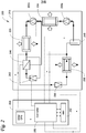
- Fig. 2 illustrates components of an embodiment of an electrically powered refrigeration module 200, which can be included in a TRU (such as the TRU 130 as illustrated in Fig. 1 ).
- the refrigeration module 200 includes an electrically powered refrigeration circuit 210 and a control circuit 260.
- the first and second stage compressors 220a and 220b can be configured to be driven by one or more electric motors (not shown).
- the main expansion valve 230 and the auxiliary expansion valve 242 can be configured to be an electro-magnetic actuated expansion valve, and/or a mechanical expansion valve.
- the inter-cooler 224, the gas cooler 225 and the evaporator 235 can be equipped with electric blowers to facilitate heat transfer. Consequently, the refrigeration circuit 210 can be configured to be powered by electricity entirely, eliminating the need for an internal combustion engine, such as a diesel engine.
- the compressors 220a and 220b may be a semi-hermetic compressor. It is to be appreciated that the refrigeration circuit 210 as illustrated in Fig. 2 is exemplary. In some embodiments, the refrigerant circuit may be configured to only have one compressor. In some embodiments, the refrigerant circuit may be configured to have a compressor that integrates two stage compression, such as a two-stage semi-hermetic compressor. In some embodiments, the refrigeration system may be configured to not have an inter-cooler. In some embodiments, the refrigeration system may be configured to use other refrigerants with a relatively low GWP, such as hydrocarbons, ammonia or other suitable types of refrigerant. Generally, the refrigeration system is configured to be electrically powered, and use refrigerant that has a relatively low GWP
- the control circuit 260 is configured to control the refrigerant circuit 210.
- the control circuit 260 includes a TRS controller 250, which may be a computer.
- the TRS controller 250 is configured to communicate with a human machine interface (HMI) 252.
- the HMI 252 may be configured to receive user inputs and communicate the user inputs to the TRS controller 250.
- the TRS controller 250 can be configured to receive information from various sources.
- the TRS controller 250 is configured to receive information from temperature and/or pressure sensors (represented by block dots in Fig. 2 ) positioned at an outlet of the gas cooler 225 and an outlet of the evaporator 235.
- the temperature and/or pressure sensors can be configured to measure, for example, temperatures and/or pressures of the refrigerant.
- the TRS controller 250 can also be configured to control the electric motors that drive the first and second stage compressor 220a and 220b so as to control the compression ratio of each compressor 220a or 220b.
- the TRS controller 250 can be further configured to control the blower speeds of the inter-cooler 224, the gas-cooler 225 and/or the evaporator 235. By controlling the blower speeds, heat transfer rates of the inter-cooler 224, the gas-cooler 225 and/or the evaporator 235 can be controlled.
- the TRS controller 250 can also be configured to control the main expansion valve 230 and/or the auxiliary expansion valve 242, so as to control an amount of refrigerant flowing into the evaporator 235 and/or the economizer 240 respectively.
- the TRS controller 250 can receive instructions from the HMI 252 and the temperature and/or pressure readings of the refrigerant from the temperature and/or pressure sensors, and determine operation parameters for the refrigerant circuit 210, such as the speeds of the electric motors for the compressors 220a, 220b, the speeds of blowers (not shown) of the inter-cooler 224, the gas cooler 225 and/or the evaporator 235, and/or the actuation of the main expansion valves 230 and the auxiliary expansion valve 242.
- the discharge temperature/pressure coming out of the compressors 220a and/or 220b can be regulated.
- the blower speeds of the inter-cooler 224, the gas cooler 225 and/or the evaporator 235 the heat transfer rates of the inter-cooler 224, the gas cooler 225 and/or the evaporator 235 can be controlled.
- the actuations of the main expansion valve 230 the suction temperature/pressure of the compressors 220a and/or 220b can be regulated.
- the auxiliary expansion valve 242 the inter-medium temperature/pressure of the compressors 220a and 220b can also be controlled.
- the TRS controller 250 may be configured to receive global positioning system (GPS) information from a GPS receiver, so that the operation parameters of the refrigeration system 210 can be determined according to the physical location of the refrigeration module 200.
- GPS global positioning system
- the TRS controller 250 may be configured to communicate with a mobile network, such as a GSM network, so that the TRS controller 250 can be controlled and/or monitored remotely through the mobile network.
- control circuit 220 can be configured to receive information from other suitable sources (e.g. box temperature sensors, ambient temperature sensors, etc.), and/or control other components of the refrigeration module 200.
- suitable sources e.g. box temperature sensors, ambient temperature sensors, etc.
- Fig. 3 illustrates another embodiment of an electrically powered refrigeration module 300 that includes a power regulating circuit 360 that is configured to be coupled to a controller circuit 320 and a refrigeration circuit 310.
- the controller circuit 320 may be configured similar to the control circuit 260as illustrated in Fig. 2
- the refrigeration circuit 310 may be configured similar to the refrigeration circuit 210 as illustrated in Fig. 2 .
- the power regulating circuit 360 is configured to receive an electric power supply, such as a DC power, from a power supply 372.
- the power supply 372 can be, for example, a power grid of a tractor (e.g. the power grid 140 as shown in Fig. 1 ), a genset, a APU, an electricity power outlet, or other suitable power supplier or storage units. Accordingly, an internal combustion engine, such as a diesel engine, may not be necessary to power the refrigeration module 300.
- the power regulating circuit 360 is configured to have a DC/AC alternator(s) 373, an AC/AC converter(s) 374, and a DC converter(s) 375.
- the DC/AC alternator(s) 373, the AC/AC converter(s) 374, and/or the DC converter(s) 375 is configured to provide one or more electrical outputs with variable voltages and/or frequencies, and is configured to be controlled by the controller circuit 320.
- a TRS controller 350 can be configured to interface with the DC/AC alternator(s) 373, the AC/AC converter(s) 374, and/or the DC converter(s) 375 and vary values for voltages and/or frequencies of the variable DC, AC outputs 380.
- These variable DC, AC outputs 380 are configured to provide power supplies to various components of the refrigeration circuit 310.
- the power regulating circuit can be configured to include all of the DC/AC alternator(s), AC/AC converter(s) and/or DC converter(s), or any combinations of these alternator(s) and/or converter(s).
- the combination of DC/AC alternator(s), AC/AC converter(s), DC converters or other suitable converters and alternators allows one or more DC and/or AC power supplies to be provided by a power regulator circuit.
- the control circuit 320 can determine the voltage and/or the frequency of each of the outputs 380 supplied to a component of the refrigeration circuit 310, so that operation of different components can be regulated by the control circuit 320. For example, by setting the voltage and/or frequency of an AC power supplied to a motor (not shown) of a compressor (e.g. the compressor 220a in Fig. 2 ), a speed of the motor can be regulated by the control circuit 320. Similarly, blower speeds for a gas cooler (e.g. the gas cooler 225) and/or an inter-cooler (e.g. the inter-cooler 224) can be regulated by the controller 350, thus operation of the gas cooler and/or the inter-cooler can be controlled by the control circuit 320.
- a gas cooler e.g. the gas cooler 225
- an inter-cooler e.g. the inter-cooler 224
- refrigerant flowing into an evaporator e.g. the evaporator 235 in Fig. 2
- the control circuit 320 By setting the voltage of a DC power supplied to an expansion valve (e.g. the expansion valve 230 in Fig.2 ), refrigerant flowing into an evaporator (e.g. the evaporator 235 in Fig. 2 ) can be regulated by the control circuit 320.
- all of the components in the refrigeration circuit 310 are configured to be electrically powered, eliminating the necessity of an internal combustion engine, such as a diesel engine.
- the control circuit 320 can control the operation of the refrigeration circuit 310 by controlling the power regulator circuit 360.
- the power regulator circuit 360 can also be configured to be coupled with a power regulator cooling circuit 390.
- the power regulator cooling circuit 390 includes a coolant pump 381, a coolant radiator 383, a coolant heat exchanger 385, and a coolant expansion tank 387.
- a coolant (not shown) circulating in the power regulator cooling circuit 390 can be water, glycerol, or any other suitable coolants.
- the coolant heat exchanger 385 may be thermally coupled to the DC/AC alternator(s) 373, the AC/AC converter(s) 374, and/or the DC converter(s) 375 (as represented in Fig. 3 by the dashed rectangular box).
- the coolant pump 381 which may be powered by the power regulator circuit 360 that is controlled by the control circuit 320 (or TRS controller 350), circulates the coolant in the power regulator cooling unit 390.
- operational temperatures of the DC/AC alternator(s) 373, the AC/AC converter(s) 374, and/or the DC converter(s) 375 can be regulated by the TRS controller 350.
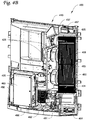
- Figs. 4A to 4C illustrate a TRU 400 that includes an electrically powered refrigeration module 410.
- the TRU 400 can be attached to a trailer, a container, a railway car, or any other suitable transport units to regulate temperatures of internal spaces of these transport units.
- a front panel 412 is configured to cover the electrically powered refrigeration system 410.
- the front panel 412 is configured to allow access to a HMI 451.
- Fig. 4B which shows a front internal view of the TRU 400 with the front panel 412 as illustrated in Fig. 4A removed
- some components of the electrically powered refrigeration system 410 are configured to be arranged on a frame 450 of the TRU 400.
- a compressor 420 is typically arranged at a lower portion 452 of the frame 450 of the TRU 400.
- the compressor 420 can be a compressor with two compression stages.
- the TRU 400 can be configured to have a separate first stage compressor and second stage compressor.
- An inter-cooler 424 and a gas cooler 425 can be arranged at a side of the TRU 400, with blowers 426 for the inter-cooler 424 and the gas cooler 425 typically positioned behind the inter-cooler 424 and the gas cooler 425.
- the blowers 426 are configured to move air through surfaces 468 of the inter-cooler 424 and the gas cooler 425 to help heat transfer.
- the frame 450 of the TRU 400 also accommodates an evaporator blower 437, which is configured to move air through an evaporator 435 (as shown in Fig. 4C ) and a cool air outlet 490 (as shown in Fig. 4C ).
- a control circuit e.g. the control unit 320 in Fig. 3
- a power regulator circuit e.g. the power regulator circuit 360
- Components of a power regulator cooling circuit can also be arranged on the frame 450 of the TRU 400.
- the coolant radiator 483 is arranged so to at least partially overlap with the inter-cooler 424 and the gas cooler 425, so that the air moved by the blowers 426 can also help move air through the coolant radiator 483.
- a back side view of the TRU 400 is illustrated in Fig. 4C .
- the back side 470 of the TRU 400 typically faces a transport unit (not shown), to which the TRU 400 is attached.
- the back side 470 of the TRU 400 includes the cool air outlet 490 that is generally in fluid communication with an internal space of the transport unit.
- the TRU 400 may also be equipped with one or more heating rods 495, which can be positioned to be overlap with the evaporator 435 (as shown in Fig. 4B .
- the heating rods 495 can be configured to be electrically powered.
- the evaporator blower 437 is configured to move air through the evaporator 435 to lower the temperature of the air, and circulates the cooled air into the internal space of the transport unit through the air outlet 490.
- the heating rods 495 can be powered on.
- the evaporator blower 437 can move air through the heating rods 495 to heat the air up so as to increase the temperature of the internal space of the transport unit, and/or remove frost.
- the heated air can be circulated into the internal space of the transport unit through the air outlet 490.
- the embodiment as shown in Figs. 4A to 4C is merely exemplary. Other suitable arrangements can be applied.
- the components in the refrigeration module can be configured to be electrically powered to eliminate the need for an internal combustion engine (e.g. a diesel engine), it is not necessary for the TRU to be configured to accommodate the internal combustion engine. Therefore, the profile and/or the weight of the TRU may be relatively smaller.
- each blower can be configured to be driven by a dedicated electric motor, there is no need to provide a belt system to drive the blowers. These features may help save manufacture costs and time associated with manufacturing and/or installing the TRU. Further, because individual components can be powered and/or driven independently, the arrangement of the components within the TRU can be more flexible.
Applications Claiming Priority (3)
| Application Number | Priority Date | Filing Date | Title |
|---|---|---|---|
| US201261703540P | 2012-09-20 | 2012-09-20 | |
| PCT/US2013/060847 WO2014047401A1 (fr) | 2012-09-20 | 2013-09-20 | Système de transport réfrigéré électrique |
| EP13838098.5A EP2897824B1 (fr) | 2012-09-20 | 2013-09-20 | Système de transport réfrigéré électrique |
Related Parent Applications (2)
| Application Number | Title | Priority Date | Filing Date |
|---|---|---|---|
| EP13838098.5A Division EP2897824B1 (fr) | 2012-09-20 | 2013-09-20 | Système de transport réfrigéré électrique |
| EP13838098.5A Division-Into EP2897824B1 (fr) | 2012-09-20 | 2013-09-20 | Système de transport réfrigéré électrique |
Publications (2)
| Publication Number | Publication Date |
|---|---|
| EP3702184A1 true EP3702184A1 (fr) | 2020-09-02 |
| EP3702184B1 EP3702184B1 (fr) | 2024-03-06 |
Family
ID=50341955
Family Applications (2)
| Application Number | Title | Priority Date | Filing Date |
|---|---|---|---|
| EP20169349.6A Active EP3702184B1 (fr) | 2012-09-20 | 2013-09-20 | Module de réfrigération de transport électrique |
| EP13838098.5A Active EP2897824B1 (fr) | 2012-09-20 | 2013-09-20 | Système de transport réfrigéré électrique |
Family Applications After (1)
| Application Number | Title | Priority Date | Filing Date |
|---|---|---|---|
| EP13838098.5A Active EP2897824B1 (fr) | 2012-09-20 | 2013-09-20 | Système de transport réfrigéré électrique |
Country Status (4)
| Country | Link |
|---|---|
| US (2) | US9776473B2 (fr) |
| EP (2) | EP3702184B1 (fr) |
| CN (2) | CN112208293A (fr) |
| WO (1) | WO2014047401A1 (fr) |
Families Citing this family (24)
| Publication number | Priority date | Publication date | Assignee | Title |
|---|---|---|---|---|
| CN112208293A (zh) * | 2012-09-20 | 2021-01-12 | 冷王公司 | 电动运输制冷系统 |
| US20140244053A1 (en) * | 2013-02-28 | 2014-08-28 | Aura Systems, Inc. | Apparatus and Method for Connecting Electrical Units |
| WO2016022877A1 (fr) | 2014-08-07 | 2016-02-11 | Thermo King Corporation | Procedes et systemes permettant a un systeme de transport refrigere de s'adapter automatiquement a une puissance d'entree |
| US10543737B2 (en) * | 2015-12-28 | 2020-01-28 | Thermo King Corporation | Cascade heat transfer system |
| FR3056289B1 (fr) * | 2016-09-16 | 2018-09-28 | Valeo Systemes Thermiques | Circuit de gestion thermique pour vehicule automobile |
| CN106671740B (zh) * | 2017-01-03 | 2023-07-21 | 埃贝思(天津)新能源技术有限公司 | 一种节能型车载制冷系统 |
| CN110612224A (zh) * | 2017-05-05 | 2019-12-24 | 开利公司 | 混合功率运输制冷系统 |
| CN110914616B (zh) | 2017-06-07 | 2022-05-24 | 开利公司 | 具有能量存储装置的运输制冷单元控制 |
| US11821661B2 (en) | 2017-06-07 | 2023-11-21 | Carrier Corporation | Energy control for a transport refrigeration unit with an energy storage device |
| US11345210B2 (en) | 2017-10-09 | 2022-05-31 | Carrier Corporation | High voltage auxiliary power unit for a transportation refrigeration system |
| EP3540340B1 (fr) | 2018-03-14 | 2023-06-28 | Carrier Corporation | Gestion de charge pour unité de camion frigorifique |
| CN110281731A (zh) * | 2018-03-19 | 2019-09-27 | 开利公司 | 冷藏卡车单元的负载管理 |
| US11073311B2 (en) * | 2018-05-17 | 2021-07-27 | Emerson Climate Technologies, Inc. | Climate-control system having pump |
| ES2905956T3 (es) * | 2018-09-20 | 2022-04-12 | Zanotti S P A | Unidad de acondicionamiento empotrable |
| EP3856550A1 (fr) * | 2018-09-28 | 2021-08-04 | Carrier Corporation | Unité de réfrigération de transport avec source d'alimentation de générateur de courant alternatif externe |
| CN111152808A (zh) * | 2018-11-08 | 2020-05-15 | 苏州迪芬德物联网科技有限公司 | 一种火车用冷藏箱远程监控系统 |
| CN110103715A (zh) * | 2019-06-04 | 2019-08-09 | 上海华羿汽车系统集成有限公司 | 一种电动商用车和供电控制方法 |
| GB202008254D0 (en) | 2020-06-02 | 2020-07-15 | Sunswap Ltd | Electric mobile refrigeration unit |
| US11738623B2 (en) | 2021-03-31 | 2023-08-29 | Thermo King Llc | Transport climate control remote management |
| KR102316363B1 (ko) * | 2021-06-22 | 2021-10-22 | 주식회사 일진정공 | 전기화물차용 저상형 전기냉동탑 |
| CN113232577B (zh) * | 2021-06-28 | 2022-09-09 | 福州市唯联高鑫智能科技有限公司 | 一种增程式冷链物流车 |
| US20230245548A1 (en) * | 2022-01-31 | 2023-08-03 | Thermo King Llc | Methods and systems for monitoring a potential hazard at an unoccupied transport unit and issuing a notification in response to detecting the hazard |
| US20230271476A1 (en) * | 2022-02-28 | 2023-08-31 | Carrier Corporation | Transport refrigeration system having direct current power sources |
| KR102539489B1 (ko) * | 2022-05-27 | 2023-06-05 | 주식회사 일진정공 | 전기냉온장탑차용 냉온장탑 |
Citations (6)
| Publication number | Priority date | Publication date | Assignee | Title |
|---|---|---|---|---|
| WO2008094148A1 (fr) * | 2007-01-31 | 2008-08-07 | Carrier Corporation | Système intégré multiple de conversion de puissance pour des unités de transport à réfrigération |
| WO2010032074A1 (fr) * | 2008-09-17 | 2010-03-25 | Carrier Corporation | Groupes frigorifiques de transport à commande électrique |
| WO2011049778A1 (fr) * | 2009-10-23 | 2011-04-28 | Carrier Corporation | Commande de paramètre dans un système de réfrigération de transport et procédés associés |
| WO2011094099A1 (fr) * | 2010-01-29 | 2011-08-04 | Carrier Corporation | Systèmes de réfrigération de transport assistés par énergie solaire, unités de réfrigération de transport et procédés pour ces systèmes et unités |
| WO2011112411A1 (fr) * | 2010-03-08 | 2011-09-15 | Carrier Corporation | Opérations et appareil de dégivrage pour un système de transport réfrigéré |
| EP2439473A1 (fr) * | 2009-06-05 | 2012-04-11 | Daikin Industries, Ltd. | Dispositif de réfrigération pour remorque |
Family Cites Families (68)
| Publication number | Priority date | Publication date | Assignee | Title |
|---|---|---|---|---|
| US3087256A (en) | 1959-04-23 | 1963-04-30 | Michel Capron | Educational test apparatus |
| US3037704A (en) | 1960-09-13 | 1962-06-05 | Kinigsberg David | Automatic control for irrigation systems |
| US3312737A (en) | 1963-03-18 | 1967-04-04 | United States Borax Chem | Preparation of organoboron compounds |
| US5245836A (en) | 1989-01-09 | 1993-09-21 | Sinvent As | Method and device for high side pressure regulation in transcritical vapor compression cycle |
| US5524681A (en) * | 1994-10-19 | 1996-06-11 | Ford Motor Company | Apparatus and method for draining and filling a battery cooling system |
| US6196012B1 (en) | 1999-03-26 | 2001-03-06 | Carrier Corporation | Generator power management |
| US6321550B1 (en) | 1999-04-21 | 2001-11-27 | Carrier Corporation | Start up control for a transport refrigeration unit with synchronous generator power system |
| US6223546B1 (en) * | 1999-04-21 | 2001-05-01 | Robert A. Chopko | Electrically powered transport refrigeration unit |
| US20020108389A1 (en) | 2001-02-15 | 2002-08-15 | Carrier Corporation | Generator with an axial air gap design for electrically powered trailer refrigeration unit |
| US20020108388A1 (en) | 2001-02-15 | 2002-08-15 | Carrier Corporation | Non-synchronous generator design for electrically powered trailer refrigeration unit |
| US6622505B2 (en) * | 2001-06-08 | 2003-09-23 | Thermo King Corporation | Alternator/invertor refrigeration unit |
| US6755041B2 (en) | 2001-07-26 | 2004-06-29 | Carrier Corporation | Electrically powered trailer refrigeration unit |
| DE10360575A1 (de) * | 2002-12-26 | 2004-07-22 | Denso Corp., Kariya | Klimagerät für ein Fahrzeug |
| US7024883B2 (en) | 2003-12-19 | 2006-04-11 | Carrier Corporation | Vapor compression systems using an accumulator to prevent over-pressurization |
| US7131294B2 (en) * | 2004-01-13 | 2006-11-07 | Tecumseh Products Company | Method and apparatus for control of carbon dioxide gas cooler pressure by use of a capillary tube |
| JP2008533426A (ja) | 2005-03-18 | 2008-08-21 | キャリア・コマーシャル・リフリージレーション・インコーポレーテッド | 遷臨界二酸化炭素冷蔵システムの凝縮水による熱伝達 |
| WO2007139554A1 (fr) | 2006-06-01 | 2007-12-06 | Carrier Corporation | Système et procédé pour un ajustement commandé de soupape de détente |
| EP2054682A4 (fr) * | 2006-08-21 | 2012-03-21 | Carrier Corp | Système de compression de vapeur avec refroidissement intermédiaire de condensat entre des stades de compression |
| DK2821731T3 (en) | 2006-09-29 | 2017-08-14 | Carrier Corp | Coolant vapor compression system with expansion tank receiver |
| DE102006048821A1 (de) * | 2006-10-09 | 2008-04-10 | Bitzer Kühlmaschinenbau Gmbh | Kühlsystem |
| WO2008054380A2 (fr) | 2006-10-27 | 2008-05-08 | Carrier Corporation | Cycle frigorifique économisé au moyen d'un détendeur |
| EP2087298A4 (fr) | 2006-11-30 | 2012-04-04 | Carrier Corp | Stockage de charge refrigerant |
| EP1935712A1 (fr) | 2006-12-22 | 2008-06-25 | Nederlandse Organisatie voor Toegepast-Natuuurwetenschappelijk Onderzoek TNO | Système et procédé pour véhicule |
| WO2008079128A1 (fr) | 2006-12-26 | 2008-07-03 | Carrier Corporation | Système de réfrigération à base de co2 équipé de compresseurs en tandem, d'un détendeur et d'un économiseur |
| US8276396B2 (en) | 2006-12-29 | 2012-10-02 | Carrier Corporation | Oil cooled generator for trailer refrigeration unit |
| US8312737B2 (en) | 2006-12-29 | 2012-11-20 | Carrier Corporation | Economizer heat exchanger |
| WO2008082410A1 (fr) | 2006-12-31 | 2008-07-10 | Carrier Corporation | Compresseur |
| CN101578491B (zh) | 2007-01-08 | 2012-07-18 | 开利公司 | 制冷运输系统 |
| CN101646909B (zh) | 2007-04-10 | 2016-07-06 | 开利公司 | 带膨胀器速度控制的制冷剂系统 |
| EP2150755A4 (fr) | 2007-04-23 | 2011-08-24 | Carrier Corp | Système de réfrigérant à co<sb>2</sb>avec circuit intensificateur |
| WO2008130357A1 (fr) | 2007-04-24 | 2008-10-30 | Carrier Corporation | Système de compression de vapeur de réfrigérant et procédé d'opération transcritique |
| JP5196452B2 (ja) | 2007-04-24 | 2013-05-15 | キャリア コーポレイション | 充填量管理を備えた遷臨界冷媒蒸気圧縮システム |
| JP2010526985A (ja) | 2007-05-14 | 2010-08-05 | キャリア コーポレイション | フラッシュタンクエコノマイザを備えた冷媒蒸気圧縮システム |
| US20100147006A1 (en) | 2007-06-04 | 2010-06-17 | Taras Michael F | Refrigerant system with cascaded circuits and performance enhancement features |
| CN101681177B (zh) | 2007-06-07 | 2013-03-06 | 开利公司 | 运输制冷单元辅助功率 |
| EP2174078A1 (fr) | 2007-07-06 | 2010-04-14 | Carrier Corporation | Alimentation électrique hybride en série de réfrigération de transport |
| WO2009014514A1 (fr) | 2007-07-24 | 2009-01-29 | Carrier Corporation | Système de gestion d'air d'évaporation pour réfrigération de remorque |
| US8087256B2 (en) | 2007-11-02 | 2012-01-03 | Cryomechanics, LLC | Cooling methods and systems using supercritical fluids |
| WO2009099429A1 (fr) | 2008-01-08 | 2009-08-13 | Carrier Corporation | Système de réfrigération comprenant une pile à combustible destinée à produire de l'électricité |
| EP2245387B1 (fr) | 2008-01-17 | 2017-12-20 | Carrier Corporation | Modulation de capacité d'un système de compression de vapeur de fluide frigorigène |
| US9958186B2 (en) | 2008-01-17 | 2018-05-01 | Carrier Corporation | Pressure relief in high pressure refrigeration system |
| US20100269523A1 (en) | 2008-01-17 | 2010-10-28 | Carrier Corporation | Mounting of pressure relief devices in a high pressure refrigeration system |
| EP2229562B1 (fr) | 2008-01-17 | 2018-09-05 | Carrier Corporation | Système de compression de vapeur de fluide frigorigène à base de dioxyde de carbone |
| ITBO20080067A1 (it) * | 2008-01-31 | 2009-08-01 | Carpigiani Group Ali Spa | Macchina per la produzione e l'erogazione di prodotti alimentari di consumo liquidi e semiliquidi. |
| JP2011512509A (ja) | 2008-02-19 | 2011-04-21 | キャリア コーポレイション | 冷媒蒸気圧縮システム |
| US20090211287A1 (en) | 2008-02-25 | 2009-08-27 | Carrier Corporation | Modular condenser fan assembly |
| US8291721B2 (en) | 2008-02-25 | 2012-10-23 | Carrier Corporation | Dual condenser fans with center partition |
| JP2011521194A (ja) | 2008-05-14 | 2011-07-21 | キャリア コーポレイション | 冷媒蒸気圧縮システムにおける充填管理 |
| JP2011521195A (ja) | 2008-05-14 | 2011-07-21 | キャリア コーポレイション | 輸送冷凍システムおよび運転方法 |
| US8037704B2 (en) | 2008-05-22 | 2011-10-18 | Thermo King Corporation | Distributed refrigeration system |
| CN102084196B (zh) | 2008-07-01 | 2013-05-08 | 开利公司 | 用于冷藏系统的起动控制 |
| WO2010003074A2 (fr) | 2008-07-04 | 2010-01-07 | Carrier Corporation | Essai de système de transport réfrigéré |
| JP2012504221A (ja) * | 2008-09-29 | 2012-02-16 | キャリア コーポレイション | プルダウン時における容量の増加 |
| JP2012504746A (ja) | 2008-10-01 | 2012-02-23 | キャリア コーポレイション | 遷臨界冷凍システムの高圧側圧力制御 |
| CN102232167B (zh) | 2008-10-01 | 2013-08-14 | 开利公司 | 跨临界制冷循环中的液体蒸气分离 |
| US9297548B2 (en) | 2008-10-31 | 2016-03-29 | Carrier Corporation | Control of multiple zone refrigerant vapor compression systems |
| EP2379959B1 (fr) * | 2008-12-29 | 2019-02-06 | Carrier Corporation | Système de réfrigération de remorque de camion |
| EP2394058B1 (fr) | 2009-02-06 | 2018-01-31 | Carrier Corporation | Compresseur de réfrigération alternatif |
| US9315088B2 (en) * | 2009-04-20 | 2016-04-19 | Green Solar Transportation Llc | Method for generating electricity from solar panels |
| CN101659186A (zh) | 2009-07-23 | 2010-03-03 | 秦畅 | 太阳能汽车遮阳降温装置 |
| WO2011066214A1 (fr) | 2009-11-25 | 2011-06-03 | Carrier Corporation | Protection contre la pression à faible aspiration pour système de compression de vapeur de réfrigérant |
| EP2545332B1 (fr) | 2010-03-08 | 2019-12-25 | Carrier Corporation | Appareils et procédés de distribution de fluide frigorigène pour un système de transport réfrigéré |
| WO2011112500A2 (fr) | 2010-03-08 | 2011-09-15 | Carrier Corporation | Commande de la capacité et de la pression dans un système de transport réfrigéré |
| US9625206B2 (en) | 2010-07-26 | 2017-04-18 | Carrier Corporation | Transport refrigeration unit with auxiliary power circuit and interlock |
| EP2694891B1 (fr) * | 2011-04-04 | 2020-01-15 | Carrier Corporation | Système de réfrigération de transport et procédé pour son fonctionnement |
| WO2013043389A1 (fr) * | 2011-09-23 | 2013-03-28 | Carrier Corporation | Système de réfrigération de transport qui utilise la chaleur perdue du moteur |
| CN102627064B (zh) * | 2012-04-23 | 2014-02-26 | 王军 | 一种车用独立式冷藏机组 |
| CN112208293A (zh) * | 2012-09-20 | 2021-01-12 | 冷王公司 | 电动运输制冷系统 |
-
2013
- 2013-09-20 CN CN202010982691.5A patent/CN112208293A/zh active Pending
- 2013-09-20 US US14/430,075 patent/US9776473B2/en active Active
- 2013-09-20 CN CN201380049142.0A patent/CN104661842A/zh active Pending
- 2013-09-20 WO PCT/US2013/060847 patent/WO2014047401A1/fr active Application Filing
- 2013-09-20 EP EP20169349.6A patent/EP3702184B1/fr active Active
- 2013-09-20 EP EP13838098.5A patent/EP2897824B1/fr active Active
-
2017
- 2017-08-30 US US15/691,177 patent/US10377209B2/en active Active
Patent Citations (6)
| Publication number | Priority date | Publication date | Assignee | Title |
|---|---|---|---|---|
| WO2008094148A1 (fr) * | 2007-01-31 | 2008-08-07 | Carrier Corporation | Système intégré multiple de conversion de puissance pour des unités de transport à réfrigération |
| WO2010032074A1 (fr) * | 2008-09-17 | 2010-03-25 | Carrier Corporation | Groupes frigorifiques de transport à commande électrique |
| EP2439473A1 (fr) * | 2009-06-05 | 2012-04-11 | Daikin Industries, Ltd. | Dispositif de réfrigération pour remorque |
| WO2011049778A1 (fr) * | 2009-10-23 | 2011-04-28 | Carrier Corporation | Commande de paramètre dans un système de réfrigération de transport et procédés associés |
| WO2011094099A1 (fr) * | 2010-01-29 | 2011-08-04 | Carrier Corporation | Systèmes de réfrigération de transport assistés par énergie solaire, unités de réfrigération de transport et procédés pour ces systèmes et unités |
| WO2011112411A1 (fr) * | 2010-03-08 | 2011-09-15 | Carrier Corporation | Opérations et appareil de dégivrage pour un système de transport réfrigéré |
Also Published As
| Publication number | Publication date |
|---|---|
| CN112208293A (zh) | 2021-01-12 |
| EP3702184B1 (fr) | 2024-03-06 |
| CN104661842A (zh) | 2015-05-27 |
| US20180015808A1 (en) | 2018-01-18 |
| EP2897824A4 (fr) | 2017-02-01 |
| US9776473B2 (en) | 2017-10-03 |
| WO2014047401A1 (fr) | 2014-03-27 |
| EP2897824A1 (fr) | 2015-07-29 |
| US10377209B2 (en) | 2019-08-13 |
| EP2897824B1 (fr) | 2020-06-03 |
| US20150239324A1 (en) | 2015-08-27 |
Similar Documents
| Publication | Publication Date | Title |
|---|---|---|
| US10377209B2 (en) | Electrical transport refrigeration system | |
| EP3144607B1 (fr) | Procedes et systemes de commande de chargement de moteur sur un systeme frigorifique de transport | |
| US11554638B2 (en) | Methods and systems for preserving autonomous operation of a transport climate control system | |
| EP3271198B1 (fr) | Unité de camion à architecture tout électrique | |
| US10150383B2 (en) | EV adaptive thermal management system optimized to minimize power consumption | |
| CN109564046B (zh) | 用于通过共晶混合物板进行容量调节的系统和方法 | |
| CN104729014B (zh) | 用于车辆的空调系统控制方法 | |
| EP2694304B1 (fr) | Système réfrigéré mobile semi-électrique | |
| CN105711376B (zh) | 电动运输制冷单元 | |
| US20150292784A1 (en) | Organic rankine cycle augmented power supply system for mobile refrigeration units | |
| KR101661667B1 (ko) | 볼텍스튜브를 이용한 차량용 공조시스템 | |
| US11305616B2 (en) | Dual compressor transportation refrigeration unit | |
| CN105531130A (zh) | 利用来自压缩流体膨胀的热容量的空调系统 | |
| US20150321539A1 (en) | Auxiliary subcooling circuit for a transport refrigeration system | |
| CN105874291B (zh) | 冷冻车辆的制冷系统 | |
| US9732993B2 (en) | Refrigerant circuit and method of controlling such a circuit | |
| US11780298B2 (en) | Heat utilisation in an environmental control system | |
| US20130047651A1 (en) | Temperature Control System in a Parked Vehicle | |
| CN106457973A (zh) | 双回路运输制冷系统 | |
| CN203163104U (zh) | 一种直流低压电驱动一体式车用电空调机 | |
| US20220203802A1 (en) | Method and system for control of a hybrid power system for powering a transport climate control system | |
| JP2022098411A (ja) | モビリティ統合熱管理システム | |
| CN102889643A (zh) | 一种超低温环境车船用空调机及其控制方法 | |
| JP2021049850A (ja) | 車両用空気調和装置 | |
| Neumeister et al. | Integration of a lithium-ion battery into hybrid and electric vehicles |
Legal Events
| Date | Code | Title | Description |
|---|---|---|---|
| PUAI | Public reference made under article 153(3) epc to a published international application that has entered the european phase |
Free format text: ORIGINAL CODE: 0009012 |
|
| STAA | Information on the status of an ep patent application or granted ep patent |
Free format text: STATUS: THE APPLICATION HAS BEEN PUBLISHED |
|
| AC | Divisional application: reference to earlier application |
Ref document number: 2897824 Country of ref document: EP Kind code of ref document: P |
|
| AK | Designated contracting states |
Kind code of ref document: A1 Designated state(s): AL AT BE BG CH CY CZ DE DK EE ES FI FR GB GR HR HU IE IS IT LI LT LU LV MC MK MT NL NO PL PT RO RS SE SI SK SM TR |
|
| STAA | Information on the status of an ep patent application or granted ep patent |
Free format text: STATUS: REQUEST FOR EXAMINATION WAS MADE |
|
| 17P | Request for examination filed |
Effective date: 20210302 |
|
| RBV | Designated contracting states (corrected) |
Designated state(s): AL AT BE BG CH CY CZ DE DK EE ES FI FR GB GR HR HU IE IS IT LI LT LU LV MC MK MT NL NO PL PT RO RS SE SI SK SM TR |
|
| STAA | Information on the status of an ep patent application or granted ep patent |
Free format text: STATUS: EXAMINATION IS IN PROGRESS |
|
| 17Q | First examination report despatched |
Effective date: 20221123 |
|
| RAP3 | Party data changed (applicant data changed or rights of an application transferred) |
Owner name: THERMO KING LLC |
|
| GRAP | Despatch of communication of intention to grant a patent |
Free format text: ORIGINAL CODE: EPIDOSNIGR1 |
|
| STAA | Information on the status of an ep patent application or granted ep patent |
Free format text: STATUS: GRANT OF PATENT IS INTENDED |
|
| INTG | Intention to grant announced |
Effective date: 20230919 |
|
| GRAS | Grant fee paid |
Free format text: ORIGINAL CODE: EPIDOSNIGR3 |
|
| GRAA | (expected) grant |
Free format text: ORIGINAL CODE: 0009210 |
|
| STAA | Information on the status of an ep patent application or granted ep patent |
Free format text: STATUS: THE PATENT HAS BEEN GRANTED |
|
| AC | Divisional application: reference to earlier application |
Ref document number: 2897824 Country of ref document: EP Kind code of ref document: P |
|
| AK | Designated contracting states |
Kind code of ref document: B1 Designated state(s): AL AT BE BG CH CY CZ DE DK EE ES FI FR GB GR HR HU IE IS IT LI LT LU LV MC MK MT NL NO PL PT RO RS SE SI SK SM TR |
|
| REG | Reference to a national code |
Ref country code: CH Ref legal event code: EP |
|
| REG | Reference to a national code |
Ref country code: IE Ref legal event code: FG4D |
|
| REG | Reference to a national code |
Ref country code: DE Ref legal event code: R096 Ref document number: 602013085424 Country of ref document: DE |
|
| P01 | Opt-out of the competence of the unified patent court (upc) registered |
Effective date: 20240304 |