EP3700852B1 - Orifice d'élingage d'un groupe motopropulseur de véhicule hybride ou électrique - Google Patents
Orifice d'élingage d'un groupe motopropulseur de véhicule hybride ou électrique Download PDFInfo
- Publication number
- EP3700852B1 EP3700852B1 EP18783550.9A EP18783550A EP3700852B1 EP 3700852 B1 EP3700852 B1 EP 3700852B1 EP 18783550 A EP18783550 A EP 18783550A EP 3700852 B1 EP3700852 B1 EP 3700852B1
- Authority
- EP
- European Patent Office
- Prior art keywords
- transmission unit
- engine
- wall
- slinging
- powertrain
- Prior art date
- Legal status (The legal status is an assumption and is not a legal conclusion. Google has not performed a legal analysis and makes no representation as to the accuracy of the status listed.)
- Active
Links
Images

Classifications
-
- B—PERFORMING OPERATIONS; TRANSPORTING
- B66—HOISTING; LIFTING; HAULING
- B66C—CRANES; LOAD-ENGAGING ELEMENTS OR DEVICES FOR CRANES, CAPSTANS, WINCHES, OR TACKLES
- B66C1/00—Load-engaging elements or devices attached to lifting or lowering gear of cranes or adapted for connection therewith for transmitting lifting forces to articles or groups of articles
- B66C1/10—Load-engaging elements or devices attached to lifting or lowering gear of cranes or adapted for connection therewith for transmitting lifting forces to articles or groups of articles by mechanical means
- B66C1/12—Slings comprising chains, wires, ropes, or bands; Nets
- B66C1/16—Slings with load-engaging platforms or frameworks
-
- B—PERFORMING OPERATIONS; TRANSPORTING
- B66—HOISTING; LIFTING; HAULING
- B66C—CRANES; LOAD-ENGAGING ELEMENTS OR DEVICES FOR CRANES, CAPSTANS, WINCHES, OR TACKLES
- B66C1/00—Load-engaging elements or devices attached to lifting or lowering gear of cranes or adapted for connection therewith for transmitting lifting forces to articles or groups of articles
- B66C1/10—Load-engaging elements or devices attached to lifting or lowering gear of cranes or adapted for connection therewith for transmitting lifting forces to articles or groups of articles by mechanical means
- B66C1/62—Load-engaging elements or devices attached to lifting or lowering gear of cranes or adapted for connection therewith for transmitting lifting forces to articles or groups of articles by mechanical means comprising article-engaging members of a shape complementary to that of the articles to be handled
- B66C1/66—Load-engaging elements or devices attached to lifting or lowering gear of cranes or adapted for connection therewith for transmitting lifting forces to articles or groups of articles by mechanical means comprising article-engaging members of a shape complementary to that of the articles to be handled for engaging holes, recesses, or abutments on articles specially provided for facilitating handling thereof
-
- F—MECHANICAL ENGINEERING; LIGHTING; HEATING; WEAPONS; BLASTING
- F16—ENGINEERING ELEMENTS AND UNITS; GENERAL MEASURES FOR PRODUCING AND MAINTAINING EFFECTIVE FUNCTIONING OF MACHINES OR INSTALLATIONS; THERMAL INSULATION IN GENERAL
- F16H—GEARING
- F16H57/00—General details of gearing
- F16H57/02—Gearboxes; Mounting gearing therein
- F16H57/033—Series gearboxes, e.g. gearboxes based on the same design being available in different sizes or gearboxes using a combination of several standardised units
Definitions
- the invention relates to the field of motor vehicles, more particularly to the handling of a powertrain during its assembly on a motor vehicle.
- the figure 1 is a diagram showing a slinging system for a thermal vehicle powertrain as described in the prior art.
- the slinging system 1 mainly comprises a slinging crane 1A on which is mounted at least one lifting sling 1B.
- the lifting sling 1B is also connected to the powertrain to be mounted in the vehicle.
- the slinging system 1 is therefore intended to allow the transport and the installation of heavy components, such as a powertrain, on a motor vehicle chassis during its assembly at the terminal plant.
- the power train of a thermal vehicle is mainly constituted by an engine-transmission unit 3.
- This unit 3 comprises a combustion engine M and a gearbox BV, both comprising an outer wall 7.
- Two sling holes 5 are provided on either side of the engine M with a view to facilitating the balancing of the engine-transmission unit 3. These slinging holes 5 are therefore positioned at the level of the center of gravity of the engine-transmission unit 3.
- the sling holes 5 are known in the prior art and can be inserts screwed onto the outer wall 7 of the engine-transmission unit 3, or else holes formed integrally with the outer wall 7 of unit 3.
- the published patent document FR 2 890 034 A1 discloses an assembly consisting of a gearbox housing and a clutch housing. This assembly further comprises an element forming a tab which is used to grip a transport tool.
- this tab is formed integrally with the gearbox housing and / or the clutch housing, which necessarily requires the design of a new mold integrating the tab into the housing. This cannot therefore be adapted to pre-existing models, or to models for which a modification in the shape of the casing would be harmful to its operation.
- the published patent document DE 10 2010 051 821 A1 discloses a transport system for a powertrain.
- the powertrain includes lifting arms with openings into which transport elements are inserted.
- the transport elements include in particular a ring which serves as a hook for the lifting slings. But the transport elements are designed to be coupled to lifting arms mounted on either side of the powertrain. This mechanism is therefore not designed to be used on pre-existing powertrains, in particular if they include a wall of complex shape.
- the document DE 81 37 354 U discloses a power train according to the preamble of claim 1 and a vehicle according to the preamble of claim 9.
- the object of the invention is to overcome at least one of the drawbacks of the above-mentioned state of the art. More particularly, the object of the invention is to facilitate the handling by slinging of an engine-transmission unit, in particular when it is capable of assuming different configurations, in a simple and economical manner.
- the subject of the invention is a powertrain, in particular for a hybrid or electric vehicle, comprising: an engine-transmission unit with an outer wall, and at least two sling holes on the engine-transmission unit, serving for fixing to a power train lifting sling, remarkable in that at least one of the sling holes is formed, in part, by a portion of the outer wall of the engine-transmission unit and, in another part, by a complementary part on said wall.
- the attached part is a support for the engine-transmission unit, intended to rest on the vehicle.
- the attached part comprises a main portion extending horizontally when the powertrain is in the mounting position on the vehicle and comprising several holes receiving screws for fixing to the engine-transmission unit, and a finger extending horizontally from the main portion.
- the finger has a hollow profile directed downwards and towards the portion of the outer wall of the engine-transmission unit.
- the finger comprises a longitudinal portion extending from a lateral section of the main portion of the insert, and an end in continuity with said longitudinal portion and which is oriented towards the portion of the outer wall of the motor unit. transmission.
- At least one of the outer wall portion of the engine-transmission unit and of the attached part forming the slinging hole has a hollow profile.
- the attached part comprises a protuberance complementary to the portion of the outer wall of the engine-transmission unit.
- the portion of the outer wall of the engine-transmission unit has a hollow profile and an annex cavity, the protuberance extending above the hollow profile with a view to forming the orifice. slinging and having one end engaging in the annex cavity.
- the slinging orifice has an outline with an opening corresponding to an air gap formed by the attached part and the portion of the outer wall of the engine-transmission unit.
- the air gap has a maximum spacing of less than 15mm and / or greater than 5mm.
- the engine-transmission unit comprises a combustion engine, a gearbox and an electric motor, the wall portion and the complementary insert, forming the slinging hole, being on the gearbox.
- the motor-transmission unit further comprises an inverter.
- the main portion of the attached part is made of a metallic material.
- the attached part further comprises a secondary portion, positioned in a longitudinal opening in the middle of the main portion, this secondary portion being made of a plastic or preferably thermoplastic material, such as an elastomer.
- the secondary portion extends vertically to the main portion and has a height similar to the latter, said secondary portion being able to facilitate the maintenance of the engine on the chassis of the vehicle and therefore to limit its vibrations.
- the secondary portion further comprises orifices, these orifices being suitable for receiving fixing screws.
- the subject of the invention is also a motor vehicle, in particular a hybrid or electric vehicle, said vehicle comprising at least: a powertrain with an engine-transmission unit and at least two slinging holes, and a frame capable of supporting the group. powerplant, remarkable in that at least one or more slinging holes is formed by a portion of an outer wall of the engine-transmission unit and by a complementary insert on said wall.
- the measures of the invention are advantageous in that they facilitate the positioning and installation of a slinging hole on the outer wall of the engine-transmission unit, regardless of the configuration of said unit. Indeed, the size of the outer wall of the engine-transmission unit as well as the impossibility of moving the various elements that compose it can make it difficult to fit a new slinging hole. The more so as the ideal zone of placement of the orifice is dependent on the center of gravity of the engine-transmission unit.
- the slinging hole according to the invention therefore has the advantage of being able to be moved and installed according to the various aforementioned factors, in order to allow efficient slinging of the engine-transmission unit to the vehicle frame.
- the invention involves a single modification in the manufacture of the insert, therefore a low cost of machining, design and ease of integration into pre-existing units.
- the machining of the metal insert is also easy.
- the use of an engine support in the context of the invention makes it possible to effectively maintain the engine-transmission unit on the chassis of the vehicle and also to limit the vibrations produced when driving said vehicle.
- the integration of the sling hole in the engine support makes it possible to limit the number of parts to be manufactured and designed, and therefore to reduce manufacturing costs.
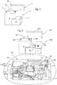
- the figure 2 shows a view of a powertrain mounted on a slinging system through at least two sling holes, as well as a magnification on the attachment area between the sling hole according to the invention and the powertrain.
- the slinging system 101 supports an engine-transmission unit 103 of the powertrain according to the invention.
- the slinging system 101 comprises, as before, a slinging crane 101A, on which are mounted one or more lifting slings 101B, the slings 101B being able to be hung, by means of a hook or a clamp, to the slinging holes 105 according to the invention.
- the engine-transmission unit 103 for its part, has the particularity, in electric or hybrid vehicles, of comprising additional components which weigh down the unit 103 and cause an imbalance if the sling holes 105 are kept in the same place as in thermal engine configurations only.
- the engine-transmission unit 103 therefore comprises a combustion engine M and a gearbox BV, to which are added an electric motor ME and an inverter O.
- the sling holes 105 are at least two in number per engine unit. -transmission 103.
- one of the orifices 105 is positioned on the engine M, the second being positioned on the gearbox BV of the engine-transmission unit 103, so as to ensure balanced lifting of said unit 103.
- the magnification shows more precisely the slinging orifice 105 mounted on the vehicle's gearbox BV.
- This slinging hole 105 is partially formed by a portion 107A of an outer wall 107 of the engine -transmission unit 103.
- the slinging hole 105 is also partially formed by a protuberance 121 of an attached part 109 complementary to the portion 107A of the outer wall 107.
- This insert 109 is more preferably a support 109 of the engine-transmission unit 103.
- these supports 109 are three in number on the engine-transmission unit 103 of the vehicle. automobile, and are intended to flexibly fix said unit 103 to the vehicle body. They thus limit the effects due to the vibrations produced by the M engine.
- the insert 109 or engine support 109 is itself constituted by a main portion 111 which extends horizontally on the upper outer wall 107 of the powertrain when the latter is mounted on the vehicle.
- the main portion 111 comprises fixing holes 113 into which are inserted fixing screws (not shown in these figures), and which serve to hold the insert 109 on the outer wall 107 of the engine-transmission unit 103
- the main portion 111 is preferably made of a metallic material.
- the insert 109 may further comprise a secondary portion 115 with fixing orifices 117 which are preferably two in number, the secondary portion 115 being mounted centrally in a central opening 119 of the main portion 111 of the insert 109.
- the secondary portion 115 of the insert 109 extends vertically over the main portion 111, and has a height similar to that of the main portion 111.
- the secondary portion 115 is preferably made of a plastic material, more preferably in a thermoplastic material such as than an elastomer, which make it possible to perform the damping function of the engine supports 109.
- the protuberance 121 From the main portion 111 of the attached part 109 extends, horizontally and laterally to said part 105, the protuberance 121, preferably forming a finger 121, and having a hollow profile directed downwards.
- the finger 121 includes a longitudinal portion 123 which extends from a side section of the main portion 111 and above the portion 107A of the outer wall 107 of the transmission unit 103.
- the longitudinal portion 123 extends towards the bottom. portion 107A of the outer wall 107 via one end 125.
- the finger 121 preferably has a diameter of between 30 and 50mm, and a resistance to at least 100kg
- the figure 3 is an enlarged view of the sling hole of the figure 2 .
- the slinging hole 105 is formed by a contour 105A formed by the portion 107A of the outer wall 107 of the engine-transmission unit 103, as well as by the lower surface of the finger 121 of the insert 109.
- the orifice sling 105 is also constituted by an opening 105B, or air gap 105B, this air gap 105B being positioned between the end 125 of the finger 121 and the portion 107A of the outer wall 107 of the engine-transmission unit 103.
- the air gap 105B has a maximum spacing less than 15mm, and / or greater than 5mm.
- the slinging hole thus has the advantage of being easily adaptable to already existing powertrains, it can also be integrated into complex structures that are difficult to modify. It is also inexpensive and can be easily made.
- the figure 4 is a diagram representative of an alternative embodiment of the invention.
- the outer wall 107 of the engine-transmission unit 103 comprises the portion 107A forming part of the slinging hole 105 and an annex cavity 107B.
- This annex cavity 107B is preferably an existing cavity on the surface of the engine-transmission unit 103.
- this annex cavity 107B is inserted the end 125 of the finger 121 of the insert 109.
- This variant makes it possible to reduce the risk of the two parts of the slinging hole 105 separating during transport of the engine-transmission unit 103.
Landscapes
- Engineering & Computer Science (AREA)
- Mechanical Engineering (AREA)
- General Engineering & Computer Science (AREA)
- Hybrid Electric Vehicles (AREA)
- Arrangement Of Transmissions (AREA)
- General Details Of Gearings (AREA)
Description
- L'invention a trait au domaine des véhicules automobiles, plus particulièrement à la manutention d'un groupe motopropulseur au cours de son montage sur un véhicule automobile.
- La
figure 1 est un schéma représentant un système d'élingage pour un groupe motopropulseur de véhicule thermique tel que décrit dans l'art antérieur. Le système d'élingage 1 comprend principalement une grue d'élingage 1A sur laquelle est montée au moins une élingue de levage 1B. L'élingue de levage 1B est également reliée au groupe motopropulseur devant être monté dans le véhicule. Le système d'élingage 1 a donc vocation à permettre le transport et la mise en place de composants lourds, tel qu'un groupe motopropulseur, sur un châssis de véhicule automobile lors de son montage à l'usine terminale. - Le groupe motopropulseur d'un véhicule thermique est principalement constitué par une unité moteur-transmission 3. Cette unité 3 comprend un moteur à combustion M et une boîte de vitesse BV, tous deux comprenant une paroi extérieure 7. Deux orifices d'élingage 5 sont prévus de part et d'autre du moteur M en vue de faciliter l'équilibrage de l'unité moteur-transmission 3. Ces orifices d'élingage 5 sont donc positionnés au niveau du centre de gravité de l'unité moteur-transmission 3. Les orifices d'élingage 5 sont connus dans l'art antérieur et peuvent être des pièces rapportées vissées sur la paroi extérieure 7 de l'unité moteur-transmission 3, ou encore des orifices formés d'un seul tenant avec la paroi extérieure 7 de l'unité 3.
- Mais dans un véhicule hybride ou électrique, l'intégration de certains composants supplémentaires à l'unité moteur-transmission est nécessaire pour son fonctionnement. Cette intégration entraîne alors une modification dans la répartition des masses de ladite unité ce qui la déséquilibre par rapport aux moteurs thermiques. De plus, la paroi extérieure de l'unité moteur-transmission est fortement contrainte de par la présence d'un grand nombre d'éléments qui sont non modifiables. Ceci rend difficile l'implantation d'un orifice d'élingage supplémentaire sur la paroi extérieure.
- Le document de brevet publié
FR 2 890 034 A1 - Le document de brevet publié
DE 10 2010 051 821 A1 divulgue un système de transport pour un groupe motopropulseur. Le groupe motopropulseur comprend des bras de levage avec des ouvertures dans lesquelles sont insérés des éléments de transport. Les éléments de transport comprennent notamment un anneau qui sert d'accroche aux élingues de levage. Mais les éléments de transport sont prévus pour être couplés à des bras de levage montés de part et d'autre du groupe motopropulseur. Ce mécanisme n'est donc pas conçu pour être utilisé sur des groupes motopropulseurs préexistants, notamment s'ils comprennent une paroi de forme complexe. Le documentDE 81 37 354 U divulgue un groupe motopropulseur selon le préambule de la revendication 1 et un véhicule selon le préambule de la revendication 9. - L'invention a pour objectif de pallier au moins un des inconvénients de l'état de la technique susmentionné. Plus particulièrement, l'invention a pour objectif de faciliter la manutention par élingage d'une unité moteur-transmission, notamment lorsqu'elle est susceptible de prendre différentes configurations, et ce de manière simple et économique.
- L'invention a pour objet un groupe motopropulseur, notamment pour un véhicule hybride ou électrique, comprenant : une unité moteur-transmission avec une paroi extérieure, et au moins deux orifices d'élingage sur l'unité moteur-transmission, servant de fixation à une élingue de levage du groupe motopropulseur, remarquable en ce qu'au moins un des orifices d'élingage est formé, en partie, par une portion de la paroi extérieure de l'unité moteur-transmission et, en une autre partie, par une pièce rapportée complémentaire sur ladite paroi.
- Selon un mode avantageux de l'invention, la pièce rapportée est un support de l'unité moteur-transmission, destinée à prendre appui sur le véhicule.
- Selon un mode avantageux de l'invention, la pièce rapportée comprend une portion principale s'étendant horizontalement lorsque le groupe motopropulseur est en position de montage sur le véhicule et comprenant plusieurs orifices recevant des vis de fixation à l'unité moteur-transmission, et un doigt s'étendant horizontalement depuis la portion principale.
- Selon un mode avantageux de l'invention, le doigt présente un profil creux dirigé vers le bas et vers la portion de la paroi extérieure de l'unité moteur-transmission.
- Avantageusement, le doigt comprend une portion longitudinale s'étendant depuis une section latérale de la portion principale de la pièce rapportée, et une extrémité en continuité avec ladite portion longitudinale et qui est orientée vers la portion de la paroi extérieure de l'unité moteur-transmission.
- Avantageusement, au moins une, de la portion de paroi extérieure de l'unité moteur-transmission et de la pièce rapportée formant l'orifice d'élingage, présente un profil creux.
- Selon un mode avantageux de l'invention, la pièce rapportée comprend une excroissance complémentaire avec la portion de la paroi extérieure de l'unité moteur-transmission.
- Selon un mode avantageux de l'invention, la portion de la paroi extérieure de l'unité moteur-transmission présente un profil creux et une cavité annexe, l'excroissance s'étendant au-dessus du profil creux en vue de former l'orifice d'élingage et ayant une extrémité engageant dans la cavité annexe.
- Selon l'invention, l'orifice d'élingage présente un contour avec une ouverture correspondant à un entrefer formé par la pièce rapportée et la portion de la paroi extérieure de l'unité moteur-transmission.
- Selon un mode avantageux de l'invention, l'entrefer présente un écartement maximum inférieur à 15mm et/ou supérieur à 5mm.
- Selon un mode avantageux de l'invention, l'unité moteur-transmission comprend un moteur à combustion, une boîte de vitesses et un moteur électrique, la portion de paroi et la pièce rapportée complémentaire, formant l'orifice d'élingage, étant sur la boîte de vitesses.
- Préférentiellement, l'unité moteur-transmission comprend en outre un onduleur. Avantageusement, la portion principale de la pièce rapportée est réalisée dans un matériau métallique. La pièce rapportée comprend en outre une portion secondaire, positionnée dans une ouverture longitudinale et médiane à la portion principale, cette portion secondaire étant réalisée dans un matériau plastique ou préférentiellement thermoplastique, tel qu'un élastomère. La portion secondaire s'étend verticalement à la portion principale et présente une hauteur similaire à celle-ci, ladite portion secondaire étant apte à faciliter le maintien du moteur sur le châssis du véhicule et donc à en limiter les vibrations. Avantageusement, la portion secondaire comprend en outre des orifices, ces orifices étant aptes à accueillir des vis de fixation.
- L'invention a également pour objet un véhicule automobile, notamment un véhicule hybride ou électrique, ledit véhicule comprenant au moins : un groupe motopropulseur avec une unité moteur-transmission et au moins deux orifices d'élingage, et un châssis apte à supporter le groupe motopropulseur, remarquable en ce qu'au moins un ou les orifices d'élingage est formé par une portion d'une paroi extérieure de l'unité moteur-transmission et par une pièce rapportée complémentaire sur ladite paroi.
- Les mesures de l'invention sont intéressantes en ce qu'elles facilitent le positionnement et l'installation d'un orifice d'élingage sur la paroi extérieure de l'unité moteur-transmission, et ce quelle que soit la configuration de ladite unité. En effet, l'encombrement de la paroi extérieure de l'unité moteur-transmission ainsi que l'impossibilité d'en déplacer les différents éléments qui la composent peuvent rendre difficile la mise en place d'un nouvel orifice d'élingage. D'autant que la zone idéale de placement de l'orifice est dépendante du centre de gravité de l'unité moteur-transmission. L'orifice d'élingage selon l'invention présente donc l'avantage de pouvoir être déplacé et installé selon les différents facteurs précités, et ce afin de permettre un élingage efficace de l'unité moteur-transmission sur le châssis du véhicule. De plus, l'invention implique une seule modification dans la fabrication de la pièce rapportée, donc un faible coût d'usinage, de conception et une facilité d'intégration aux unités préexistantes. L'usinage de la pièce rapportée métallique est également aisé. L'utilisation d'un support moteur dans le cadre de l'invention permet de maintenir efficacement l'unité moteur-transmission sur le châssis du véhicule et également de limiter les vibrations produites lors de la conduite dudit véhicule. Enfin, l'intégration de l'orifice d'élingage au support moteur permet de limiter le nombre de pièces à fabriquer et à concevoir, donc de réduire les coûts de fabrication.
- D'autres caractéristiques et avantages de la présente invention seront mieux compris à l'aide de la description et des dessins parmi lesquels :
- La
figure 1 est un schéma représentant un système d'élingage pour un moteur thermique tel que décrit dans l'art antérieur, - La
figure 2 est un schéma représentant un système d'élingage pour un moteur hybride ou un moteur électrique avec un grossissement sur un orifice d'élingage selon l'invention, - La
figure 3 est un grossissement de l'orifice d'élingage de lafigure 2 , - La
figure 4 est un schéma représentant une variante de réalisation de l'invention. - La
figure 1 est décrite précédemment en relation avec l'état de la technique. - La
figure 2 montre une vue d'un groupe motopropulseur monté sur un système d'élingage par le biais d'au moins deux orifices d'élingage, ainsi qu'un grossissement sur la zone de fixation entre l'orifice d'élingage selon l'invention et le groupe motopropulseur. - Le système d'élingage 101 supporte une unité moteur-transmission 103 du groupe motopropulseur selon l'invention. Le système d'élingage 101 comprend comme précédemment une grue d'élingage 101A, sur laquelle sont montées une ou plusieurs élingues de levage 101B, les élingues 101B étant aptes à être accrochées, par le biais d'un crochet ou d'une pince, aux orifices d'élingage 105 selon l'invention. L'unité moteur-transmission 103 à quant à elle la particularité, dans les véhicules électriques ou hybrides, de comporter des composants supplémentaires qui alourdissent l'unité 103 et provoquent un déséquilibre si les orifices d'élingages 105 sont conservés à la même place que dans les configurations à moteur thermique uniquement. L'unité moteur-transmission 103 comprend donc un moteur à combustion M et une boîte de vitesse BV, auxquels s'ajoutent un moteur électrique ME et un onduleur O. Les orifices d'élingages 105 sont au moins au nombre de deux par unité moteur-transmission 103. Préférentiellement, l'un des orifices 105 est positionné sur le moteur M, le deuxième étant positionné sur la boîte de vitesse BV de l'unité moteur-transmission 103, de manière à assurer un levage équilibré de ladite unité 103.
- Le grossissement montre plus précisément l'orifice d'élingage 105 monté sur la boîte de vitesse BV du véhicule. Cet orifice d'élingage 105 est partiellement constitué d'une portion 107A d'une paroi extérieure 107 de l'unité moteur -transmission 103. L'orifice d'élingage 105 est également partiellement constitué par une excroissance 121 d'une pièce rapportée 109 complémentaire à la portion 107A de la paroi extérieure 107. Cette pièce rapportée 109 est plus préférentiellement un support 109 de l'unité moteur-transmission 103. Classiquement, ces supports 109 sont au nombre de trois sur l'unité moteur-transmission 103 du véhicule automobile, et ont vocation à fixer de manière souple ladite unité 103 à la caisse du véhicule. Ils limitent ainsi les effets dus aux vibrations produites par le moteur M.
- La pièce rapportée 109 ou support moteur 109 est elle-même constituée par une portion principale 111 qui s'étend horizontalement sur la paroi extérieure 107 supérieure du groupe motopropulseur quand celui-ci est monté sur le véhicule. La portion principale 111 comprend des orifices de fixation 113 dans lesquels s'insèrent des vis de fixation (non représentées sur ces figures), et qui servent au maintien de la pièce rapportée 109 sur la paroi extérieure 107 de l'unité moteur-transmission 103. La portion principale 111 est préférentiellement réalisée dans un matériau métallique. La pièce rapportée 109 peut comprendre en outre une portion secondaire 115 avec des orifices de fixation 117 qui sont préférentiellement au nombre de deux, la portion secondaire 115 étant montée centralement dans une ouverture médiane 119 de la portion principale 111 de la pièce rapportée 109. La portion secondaire 115 de la pièce rapportée 109 s'étend verticalement sur la portion principale 111, et présente une hauteur similaire à celle de la portion principale 111. La portion secondaire 115 est préférentiellement réalisée dans un matériau plastique, plus préférentiellement dans un matériau thermoplastique tel qu'un élastomère, qui permettent de réaliser la fonction d'amortissement des supports moteurs 109. De la portion principale 111 de la pièce rapportée 109 s'étend, horizontalement et latéralement à ladite pièce 105, l'excroissance 121, formant préférentiellement un doigt 121, et présentant un profil creux dirigé vers le bas. Le doigt 121 comprend une portion longitudinale 123 qui s'étend depuis une section latérale de la portion principale 111 et au-dessus de la portion 107A de la paroi extérieure 107 de l'unité de transmission 103. La portion longitudinale 123 se prolonge vers la portion 107A de la paroi extérieure 107 par une extrémité 125. Le doigt 121 présente préférentiellement un diamètre compris entre 30 et 50mm, et une résistance à au moins 100kg de charge.
- La
figure 3 est une vue agrandie de l'orifice d'élingage de lafigure 2 . L'orifice d'élingage 105 est constitué par un contour 105A formé par la portion 107A de la paroi extérieure 107 de l'unité moteur-transmission 103, ainsi que par la surface inférieure du doigt 121 de la pièce rapportée 109. L'orifice d'élingage 105 est également constitué par une ouverture 105B, ou entrefer 105B, cet entrefer 105B étant positionné entre l'extrémité 125 du doigt 121 et la portion 107A de la paroi extérieure 107 de l'unité moteur-transmission 103. L'entrefer 105B présente un écartement maximum inférieur à 15mm, et/ou supérieur à 5mm. - L'orifice d'élingage présente ainsi l'avantage d'être facilement adaptable à des groupes motopropulseurs déjà existants, il peut également s'intégrer à des structures complexes et difficilement modifiables. Il est également peu coûteux et peut être facilement fabriqué.
- La
figure 4 est un schéma représentatif d'une variante de réalisation de l'invention. La paroi extérieure 107 de l'unité moteur-transmission 103 comprend la portion 107A formant une partie de l'orifice d'élingage 105 et une cavité annexe 107B. Cette cavité annexe 107B est préférentiellement une cavité existante à la surface de l'unité moteur-transmission 103. Dans cette cavité annexe 107B s'insère l'extrémité 125 du doigt 121 de la pièce rapportée 109. Cette variante permet de diminuer le risque de séparation des deux parties de l'orifice d'élingage 105 lors du transport de l'unité moteur-transmission 103.
Claims (9)
- Groupe motopropulseur, notamment pour un véhicule hybride ou électrique, comprenant :- une unité moteur-transmission (3; 103) avec une paroi extérieure (7 ; 107), et- au moins deux orifices d'élingage (5 ; 105) sur l'unité moteur-transmission (3; 103), servant de fixation à une élingue de levage (1B; 101B) du groupe motopropulseur,- au moins un des orifices d'élingage (105) étant formé, en partie, par une portion (107A) de la paroi extérieure (107) de l'unité moteur-transmission (103) et, en une autre partie, par une pièce rapportée (109) complémentaire sur ladite paroi (107),caractérisé en ce que l'orifice d'élingage (105) présente un contour (105A) avec une ouverture (105B) correspondant à un entrefer (105B) formé par la pièce rapportée (109) et la portion (107A) de la paroi extérieure (107) de l'unité moteur-transmission (103).
- Groupe motopropulseur selon la revendication 1, caractérisé en ce que la pièce rapportée (109) est un support (109) de l'unité moteur-transmission (103), destinée à prendre appui sur le véhicule.
- Groupe motopropulseur selon l'une des revendications 1 ou 2, caractérisé en ce que la pièce rapportée (109) comprend :- une portion principale (111) s'étendant horizontalement lorsque le groupe motopropulseur est en position de montage sur le véhicule et comprenant plusieurs orifices (113) recevant des vis de fixation à l'unité moteur-transmission (103), et- un doigt (121) s'étendant horizontalement depuis la portion principale (111).
- Groupe motopropulseur selon la revendication 3, caractérisé en ce que le doigt (121) présente un profil creux dirigé vers le bas et vers la portion (107A) de la paroi extérieure (107) de l'unité moteur-transmission (103).
- Groupe motopropulseur selon l'une des revendications 1 à 4, caractérisé en ce que la pièce rapportée (109) comprend une excroissance (121) complémentaire avec la portion (107A) de la paroi extérieure (107) de l'unité moteur-transmission (103).
- Groupe motopropulseur selon la revendication 5, caractérisé en ce que la portion (107A) de la paroi extérieure (107) de l'unité moteur-transmission (103) présente un profil creux et une cavité annexe (107B), l'excroissance (121) s'étendant au-dessus du profil creux en vue de former l'orifice d'élingage (105) et ayant une extrémité (125) engageant dans la cavité annexe (107B).
- Groupe motopropulseur selon l'une des revendications 1 à 6, caractérisé en ce que l'entrefer (105B) présente un écartement maximum inférieur à 15mm et/ou supérieur à 5mm.
- Groupe motopropulseur selon l'une des revendications 1 à 7, caractérisé en ce que l'unité moteur-transmission (103) comprend un moteur à combustion (M), une boîte de vitesses (BV) et un moteur électrique (ME), la portion (107A) de paroi (107) et la pièce rapportée (109) complémentaire, formant l'orifice d'élingage (105), étant sur la boîte de vitesses (BV).
- Véhicule automobile, notamment un véhicule hybride ou électrique, ledit véhicule comprenant au moins :- un groupe motopropulseur avec une unité moteur-transmission (3 ; 103) et au moins deux orifices d'élingage (5 ; 105) et- un châssis apte à supporter le groupe motopropulseur,- un ou les orifices d'élingage (105) étant formé par une portion (107A) d'une paroi extérieure (107) de l'unité moteur-transmission (103) et par une pièce rapportée (109) complémentaire sur ladite paroi (107),caractérisé en ce que l'orifice d'élingage (105) présente un contour (105A) avec une ouverture (105B) correspondant à un entrefer (105B) formé par la pièce rapportée (109) et la portion (107A) de la paroi extérieure (107) de l'unité moteur-transmission (103).
Applications Claiming Priority (2)
| Application Number | Priority Date | Filing Date | Title |
|---|---|---|---|
| FR1760016A FR3072641B1 (fr) | 2017-10-24 | 2017-10-24 | Orifice d’elingage d’un groupe motopropulseur de vehicule hybride ou electrique |
| PCT/FR2018/052322 WO2019081827A1 (fr) | 2017-10-24 | 2018-09-24 | Orifice d'élingage d'un groupe motopropulseur de véhicule hybride ou électrique |
Publications (2)
| Publication Number | Publication Date |
|---|---|
| EP3700852A1 EP3700852A1 (fr) | 2020-09-02 |
| EP3700852B1 true EP3700852B1 (fr) | 2021-10-27 |
Family
ID=60888503
Family Applications (1)
| Application Number | Title | Priority Date | Filing Date |
|---|---|---|---|
| EP18783550.9A Active EP3700852B1 (fr) | 2017-10-24 | 2018-09-24 | Orifice d'élingage d'un groupe motopropulseur de véhicule hybride ou électrique |
Country Status (3)
| Country | Link |
|---|---|
| EP (1) | EP3700852B1 (fr) |
| FR (1) | FR3072641B1 (fr) |
| WO (1) | WO2019081827A1 (fr) |
Family Cites Families (4)
| Publication number | Priority date | Publication date | Assignee | Title |
|---|---|---|---|---|
| DE8137354U1 (de) * | 1981-12-22 | 1982-07-01 | Fa. August Thiele, 5860 Iserlohn | Anschlußvorrichtung |
| DE112006002775A5 (de) * | 2005-08-31 | 2008-08-28 | Ksm Castings Gmbh | Aus einem Getriebe- und einem Kupplungsgehäuse zusammengesetztes Aggregat |
| FR2928906A3 (fr) * | 2008-03-20 | 2009-09-25 | Renault Sas | Anneau de levage de bloc moteur,ensemble comportant un bloc-moteur et un tel anneau de levage,et vehicule automobile correspondant |
| DE102010051821A1 (de) * | 2010-11-18 | 2012-05-24 | GM Global Technology Operations LLC | Transportvorrichtung zum Transportieren eines Antriebsaggregats eines Fahrzeugs und Verfahren zum Herstellen der Transportvorrichtung und zum Transportieren des Antriebsaggregats |
-
2017
- 2017-10-24 FR FR1760016A patent/FR3072641B1/fr not_active Expired - Fee Related
-
2018
- 2018-09-24 WO PCT/FR2018/052322 patent/WO2019081827A1/fr not_active Ceased
- 2018-09-24 EP EP18783550.9A patent/EP3700852B1/fr active Active
Also Published As
| Publication number | Publication date |
|---|---|
| WO2019081827A1 (fr) | 2019-05-02 |
| FR3072641A1 (fr) | 2019-04-26 |
| FR3072641B1 (fr) | 2020-01-03 |
| EP3700852A1 (fr) | 2020-09-02 |
Similar Documents
| Publication | Publication Date | Title |
|---|---|---|
| EP2595857B1 (fr) | Chassis de vehicule automobile avec piece de fixation d'elements de carrosserie et de cables electriques au plancher central | |
| EP3307578B1 (fr) | Traverse en aluminium extrudé et à zones longitudinales pleines, pour la suspension d'une machine électrique motrice d'un véhicule | |
| EP2266829B1 (fr) | Support antivibratoire à limitation de mouvement | |
| EP4304901B1 (fr) | Dispositif de support du chargeur de batterie des vehicules automobiles | |
| EP0968865A1 (fr) | Agencement pour un groupe motopropulseur électrique | |
| EP3700852A1 (fr) | Orifice d'élingage d'un groupe motopropulseur de véhicule hybride ou électrique | |
| WO2019012194A1 (fr) | Dispositif monobloc de support d'un groupe motopropulseur integrant un palier relais | |
| EP3401559B1 (fr) | Dispositif anti-vibration à fonction de pré-maintien, pour un dispositif fonctionnel | |
| EP3423733B1 (fr) | Dispositif d'amortissement de vibrations entre un premier élément vibrant et un deuxième élément | |
| EP3377349B1 (fr) | Vehicule electrique terrestre de transport en commun, de type bus, muni de modules de stockage d'energie electrique interieurs | |
| EP3656626B1 (fr) | Plancher d'un véhicule ferroviaire et procédé de montage associé | |
| WO2016020589A1 (fr) | Panneau arrière de véhicule automobile | |
| FR2973088A1 (fr) | Support antivibratoire et vehicule comportant un tel support | |
| EP1375971B1 (fr) | Enceinte de boíte de vitesses et boíte de vitesses pilotée équipée d'une telle enceinte | |
| WO2001014647A1 (fr) | Dispositif de liaison stable du type tripode, interpose entre un receptacle et un couvercle, et ensemble ainsi constitue | |
| FR3130332A1 (fr) | Ensemble de fixation d’un organe fonctionnel dans un habitacle | |
| FR3075699B1 (fr) | Support de moteur electrique comprenant un conduit integre et groupe motopropulseur comprenant un tel support | |
| WO2024079088A1 (fr) | Agencement de fixation d'un reniflard dans un véhicule | |
| WO2014079908A1 (fr) | Dispositif de réception d'un élément de suspension d'un véhicule automobile, agencement comportant deux dispositifs identiques, et procédé de fabrication de l'agencement | |
| FR2981877A1 (fr) | Dispositif d'accrochage d'une machine-outil portative | |
| EP3969710A1 (fr) | Butée de surclaquage pour capot de véhicule automobile | |
| FR3087693A1 (fr) | Prehenseur avec tuyau flexible interne d’alimentation | |
| WO2017162943A1 (fr) | Fixation d'un systeme de gestion d'air d'une entree d'air pour face avant de vehicule | |
| EP1291544A1 (fr) | Support antivibratoire et véhicule comportant un tel support | |
| FR3093982A1 (fr) | Ensemble de refroidissement d’un véhicule automobile |
Legal Events
| Date | Code | Title | Description |
|---|---|---|---|
| STAA | Information on the status of an ep patent application or granted ep patent |
Free format text: STATUS: UNKNOWN |
|
| STAA | Information on the status of an ep patent application or granted ep patent |
Free format text: STATUS: THE INTERNATIONAL PUBLICATION HAS BEEN MADE |
|
| PUAI | Public reference made under article 153(3) epc to a published international application that has entered the european phase |
Free format text: ORIGINAL CODE: 0009012 |
|
| STAA | Information on the status of an ep patent application or granted ep patent |
Free format text: STATUS: REQUEST FOR EXAMINATION WAS MADE |
|
| 17P | Request for examination filed |
Effective date: 20200518 |
|
| AK | Designated contracting states |
Kind code of ref document: A1 Designated state(s): AL AT BE BG CH CY CZ DE DK EE ES FI FR GB GR HR HU IE IS IT LI LT LU LV MC MK MT NL NO PL PT RO RS SE SI SK SM TR |
|
| AX | Request for extension of the european patent |
Extension state: BA ME |
|
| RAP1 | Party data changed (applicant data changed or rights of an application transferred) |
Owner name: PSA AUTOMOBILES SA |
|
| DAV | Request for validation of the european patent (deleted) | ||
| DAX | Request for extension of the european patent (deleted) | ||
| GRAP | Despatch of communication of intention to grant a patent |
Free format text: ORIGINAL CODE: EPIDOSNIGR1 |
|
| STAA | Information on the status of an ep patent application or granted ep patent |
Free format text: STATUS: GRANT OF PATENT IS INTENDED |
|
| INTG | Intention to grant announced |
Effective date: 20210630 |
|
| GRAS | Grant fee paid |
Free format text: ORIGINAL CODE: EPIDOSNIGR3 |
|
| GRAA | (expected) grant |
Free format text: ORIGINAL CODE: 0009210 |
|
| STAA | Information on the status of an ep patent application or granted ep patent |
Free format text: STATUS: THE PATENT HAS BEEN GRANTED |
|
| AK | Designated contracting states |
Kind code of ref document: B1 Designated state(s): AL AT BE BG CH CY CZ DE DK EE ES FI FR GB GR HR HU IE IS IT LI LT LU LV MC MK MT NL NO PL PT RO RS SE SI SK SM TR |
|
| REG | Reference to a national code |
Ref country code: GB Ref legal event code: FG4D Free format text: NOT ENGLISH |
|
| REG | Reference to a national code |
Ref country code: CH Ref legal event code: EP |
|
| REG | Reference to a national code |
Ref country code: AT Ref legal event code: REF Ref document number: 1441626 Country of ref document: AT Kind code of ref document: T Effective date: 20211115 |
|
| REG | Reference to a national code |
Ref country code: DE Ref legal event code: R096 Ref document number: 602018025794 Country of ref document: DE |
|
| REG | Reference to a national code |
Ref country code: IE Ref legal event code: FG4D Free format text: LANGUAGE OF EP DOCUMENT: FRENCH |
|
| REG | Reference to a national code |
Ref country code: GB Ref legal event code: 746 Effective date: 20211124 |
|
| REG | Reference to a national code |
Ref country code: LT Ref legal event code: MG9D |
|
| REG | Reference to a national code |
Ref country code: NL Ref legal event code: MP Effective date: 20211027 |
|
| REG | Reference to a national code |
Ref country code: AT Ref legal event code: MK05 Ref document number: 1441626 Country of ref document: AT Kind code of ref document: T Effective date: 20211027 |
|
| PG25 | Lapsed in a contracting state [announced via postgrant information from national office to epo] |
Ref country code: RS Free format text: LAPSE BECAUSE OF FAILURE TO SUBMIT A TRANSLATION OF THE DESCRIPTION OR TO PAY THE FEE WITHIN THE PRESCRIBED TIME-LIMIT Effective date: 20211027 Ref country code: LT Free format text: LAPSE BECAUSE OF FAILURE TO SUBMIT A TRANSLATION OF THE DESCRIPTION OR TO PAY THE FEE WITHIN THE PRESCRIBED TIME-LIMIT Effective date: 20211027 Ref country code: FI Free format text: LAPSE BECAUSE OF FAILURE TO SUBMIT A TRANSLATION OF THE DESCRIPTION OR TO PAY THE FEE WITHIN THE PRESCRIBED TIME-LIMIT Effective date: 20211027 Ref country code: BG Free format text: LAPSE BECAUSE OF FAILURE TO SUBMIT A TRANSLATION OF THE DESCRIPTION OR TO PAY THE FEE WITHIN THE PRESCRIBED TIME-LIMIT Effective date: 20220127 Ref country code: AT Free format text: LAPSE BECAUSE OF FAILURE TO SUBMIT A TRANSLATION OF THE DESCRIPTION OR TO PAY THE FEE WITHIN THE PRESCRIBED TIME-LIMIT Effective date: 20211027 |
|
| PG25 | Lapsed in a contracting state [announced via postgrant information from national office to epo] |
Ref country code: IS Free format text: LAPSE BECAUSE OF FAILURE TO SUBMIT A TRANSLATION OF THE DESCRIPTION OR TO PAY THE FEE WITHIN THE PRESCRIBED TIME-LIMIT Effective date: 20220227 Ref country code: SE Free format text: LAPSE BECAUSE OF FAILURE TO SUBMIT A TRANSLATION OF THE DESCRIPTION OR TO PAY THE FEE WITHIN THE PRESCRIBED TIME-LIMIT Effective date: 20211027 Ref country code: PT Free format text: LAPSE BECAUSE OF FAILURE TO SUBMIT A TRANSLATION OF THE DESCRIPTION OR TO PAY THE FEE WITHIN THE PRESCRIBED TIME-LIMIT Effective date: 20220228 Ref country code: PL Free format text: LAPSE BECAUSE OF FAILURE TO SUBMIT A TRANSLATION OF THE DESCRIPTION OR TO PAY THE FEE WITHIN THE PRESCRIBED TIME-LIMIT Effective date: 20211027 Ref country code: NO Free format text: LAPSE BECAUSE OF FAILURE TO SUBMIT A TRANSLATION OF THE DESCRIPTION OR TO PAY THE FEE WITHIN THE PRESCRIBED TIME-LIMIT Effective date: 20220127 Ref country code: NL Free format text: LAPSE BECAUSE OF FAILURE TO SUBMIT A TRANSLATION OF THE DESCRIPTION OR TO PAY THE FEE WITHIN THE PRESCRIBED TIME-LIMIT Effective date: 20211027 Ref country code: LV Free format text: LAPSE BECAUSE OF FAILURE TO SUBMIT A TRANSLATION OF THE DESCRIPTION OR TO PAY THE FEE WITHIN THE PRESCRIBED TIME-LIMIT Effective date: 20211027 Ref country code: HR Free format text: LAPSE BECAUSE OF FAILURE TO SUBMIT A TRANSLATION OF THE DESCRIPTION OR TO PAY THE FEE WITHIN THE PRESCRIBED TIME-LIMIT Effective date: 20211027 Ref country code: GR Free format text: LAPSE BECAUSE OF FAILURE TO SUBMIT A TRANSLATION OF THE DESCRIPTION OR TO PAY THE FEE WITHIN THE PRESCRIBED TIME-LIMIT Effective date: 20220128 Ref country code: ES Free format text: LAPSE BECAUSE OF FAILURE TO SUBMIT A TRANSLATION OF THE DESCRIPTION OR TO PAY THE FEE WITHIN THE PRESCRIBED TIME-LIMIT Effective date: 20211027 |
|
| REG | Reference to a national code |
Ref country code: DE Ref legal event code: R097 Ref document number: 602018025794 Country of ref document: DE |
|
| PG25 | Lapsed in a contracting state [announced via postgrant information from national office to epo] |
Ref country code: SM Free format text: LAPSE BECAUSE OF FAILURE TO SUBMIT A TRANSLATION OF THE DESCRIPTION OR TO PAY THE FEE WITHIN THE PRESCRIBED TIME-LIMIT Effective date: 20211027 Ref country code: SK Free format text: LAPSE BECAUSE OF FAILURE TO SUBMIT A TRANSLATION OF THE DESCRIPTION OR TO PAY THE FEE WITHIN THE PRESCRIBED TIME-LIMIT Effective date: 20211027 Ref country code: RO Free format text: LAPSE BECAUSE OF FAILURE TO SUBMIT A TRANSLATION OF THE DESCRIPTION OR TO PAY THE FEE WITHIN THE PRESCRIBED TIME-LIMIT Effective date: 20211027 Ref country code: EE Free format text: LAPSE BECAUSE OF FAILURE TO SUBMIT A TRANSLATION OF THE DESCRIPTION OR TO PAY THE FEE WITHIN THE PRESCRIBED TIME-LIMIT Effective date: 20211027 Ref country code: DK Free format text: LAPSE BECAUSE OF FAILURE TO SUBMIT A TRANSLATION OF THE DESCRIPTION OR TO PAY THE FEE WITHIN THE PRESCRIBED TIME-LIMIT Effective date: 20211027 Ref country code: CZ Free format text: LAPSE BECAUSE OF FAILURE TO SUBMIT A TRANSLATION OF THE DESCRIPTION OR TO PAY THE FEE WITHIN THE PRESCRIBED TIME-LIMIT Effective date: 20211027 |
|
| PLBE | No opposition filed within time limit |
Free format text: ORIGINAL CODE: 0009261 |
|
| STAA | Information on the status of an ep patent application or granted ep patent |
Free format text: STATUS: NO OPPOSITION FILED WITHIN TIME LIMIT |
|
| 26N | No opposition filed |
Effective date: 20220728 |
|
| PG25 | Lapsed in a contracting state [announced via postgrant information from national office to epo] |
Ref country code: AL Free format text: LAPSE BECAUSE OF FAILURE TO SUBMIT A TRANSLATION OF THE DESCRIPTION OR TO PAY THE FEE WITHIN THE PRESCRIBED TIME-LIMIT Effective date: 20211027 |
|
| PG25 | Lapsed in a contracting state [announced via postgrant information from national office to epo] |
Ref country code: SI Free format text: LAPSE BECAUSE OF FAILURE TO SUBMIT A TRANSLATION OF THE DESCRIPTION OR TO PAY THE FEE WITHIN THE PRESCRIBED TIME-LIMIT Effective date: 20211027 |
|
| PG25 | Lapsed in a contracting state [announced via postgrant information from national office to epo] |
Ref country code: MC Free format text: LAPSE BECAUSE OF FAILURE TO SUBMIT A TRANSLATION OF THE DESCRIPTION OR TO PAY THE FEE WITHIN THE PRESCRIBED TIME-LIMIT Effective date: 20211027 |
|
| REG | Reference to a national code |
Ref country code: CH Ref legal event code: PL |
|
| REG | Reference to a national code |
Ref country code: BE Ref legal event code: MM Effective date: 20220930 |
|
| PG25 | Lapsed in a contracting state [announced via postgrant information from national office to epo] |
Ref country code: IT Free format text: LAPSE BECAUSE OF FAILURE TO SUBMIT A TRANSLATION OF THE DESCRIPTION OR TO PAY THE FEE WITHIN THE PRESCRIBED TIME-LIMIT Effective date: 20211027 |
|
| PG25 | Lapsed in a contracting state [announced via postgrant information from national office to epo] |
Ref country code: LU Free format text: LAPSE BECAUSE OF NON-PAYMENT OF DUE FEES Effective date: 20220924 |
|
| PG25 | Lapsed in a contracting state [announced via postgrant information from national office to epo] |
Ref country code: LI Free format text: LAPSE BECAUSE OF NON-PAYMENT OF DUE FEES Effective date: 20220930 Ref country code: IE Free format text: LAPSE BECAUSE OF NON-PAYMENT OF DUE FEES Effective date: 20220924 Ref country code: CH Free format text: LAPSE BECAUSE OF NON-PAYMENT OF DUE FEES Effective date: 20220930 |
|
| PG25 | Lapsed in a contracting state [announced via postgrant information from national office to epo] |
Ref country code: BE Free format text: LAPSE BECAUSE OF NON-PAYMENT OF DUE FEES Effective date: 20220930 |
|
| REG | Reference to a national code |
Ref country code: DE Ref legal event code: R081 Ref document number: 602018025794 Country of ref document: DE Owner name: STELLANTIS AUTO SAS, FR Free format text: FORMER OWNER: PSA AUTOMOBILES SA, POISSY, FR |
|
| PG25 | Lapsed in a contracting state [announced via postgrant information from national office to epo] |
Ref country code: CY Free format text: LAPSE BECAUSE OF FAILURE TO SUBMIT A TRANSLATION OF THE DESCRIPTION OR TO PAY THE FEE WITHIN THE PRESCRIBED TIME-LIMIT Effective date: 20211027 |
|
| PG25 | Lapsed in a contracting state [announced via postgrant information from national office to epo] |
Ref country code: MK Free format text: LAPSE BECAUSE OF FAILURE TO SUBMIT A TRANSLATION OF THE DESCRIPTION OR TO PAY THE FEE WITHIN THE PRESCRIBED TIME-LIMIT Effective date: 20211027 Ref country code: HU Free format text: LAPSE BECAUSE OF FAILURE TO SUBMIT A TRANSLATION OF THE DESCRIPTION OR TO PAY THE FEE WITHIN THE PRESCRIBED TIME-LIMIT; INVALID AB INITIO Effective date: 20180924 |
|
| PG25 | Lapsed in a contracting state [announced via postgrant information from national office to epo] |
Ref country code: TR Free format text: LAPSE BECAUSE OF FAILURE TO SUBMIT A TRANSLATION OF THE DESCRIPTION OR TO PAY THE FEE WITHIN THE PRESCRIBED TIME-LIMIT Effective date: 20211027 |
|
| PG25 | Lapsed in a contracting state [announced via postgrant information from national office to epo] |
Ref country code: MT Free format text: LAPSE BECAUSE OF FAILURE TO SUBMIT A TRANSLATION OF THE DESCRIPTION OR TO PAY THE FEE WITHIN THE PRESCRIBED TIME-LIMIT Effective date: 20211027 |
|
| PGFP | Annual fee paid to national office [announced via postgrant information from national office to epo] |
Ref country code: GB Payment date: 20250822 Year of fee payment: 8 |
|
| PGFP | Annual fee paid to national office [announced via postgrant information from national office to epo] |
Ref country code: FR Payment date: 20250820 Year of fee payment: 8 |
|
| PGFP | Annual fee paid to national office [announced via postgrant information from national office to epo] |
Ref country code: DE Payment date: 20251209 Year of fee payment: 8 |