EP3699518B1 - Kühlschrank - Google Patents
Kühlschrank Download PDFInfo
- Publication number
- EP3699518B1 EP3699518B1 EP19201726.7A EP19201726A EP3699518B1 EP 3699518 B1 EP3699518 B1 EP 3699518B1 EP 19201726 A EP19201726 A EP 19201726A EP 3699518 B1 EP3699518 B1 EP 3699518B1
- Authority
- EP
- European Patent Office
- Prior art keywords
- oxygen
- freshness
- air
- space
- keeping
- Prior art date
- Legal status (The legal status is an assumption and is not a legal conclusion. Google has not performed a legal analysis and makes no representation as to the accuracy of the status listed.)
- Active
Links
Images


Classifications
-
- A—HUMAN NECESSITIES
- A23—FOODS OR FOODSTUFFS; TREATMENT THEREOF, NOT COVERED BY OTHER CLASSES
- A23B—PRESERVATION OF FOODS, FOODSTUFFS OR NON-ALCOHOLIC BEVERAGES; CHEMICAL RIPENING OF FRUIT OR VEGETABLES
- A23B2/00—Preservation of foods or foodstuffs, in general
- A23B2/80—Freezing; Subsequent thawing; Cooling
- A23B2/805—Materials not being transported through or in the apparatus with or without shaping, e.g. in the form of powders, granules or flakes
-
- C—CHEMISTRY; METALLURGY
- C01—INORGANIC CHEMISTRY
- C01B—NON-METALLIC ELEMENTS; COMPOUNDS THEREOF; METALLOIDS OR COMPOUNDS THEREOF NOT COVERED BY SUBCLASS C01C
- C01B13/00—Oxygen; Ozone; Oxides or hydroxides in general
- C01B13/02—Preparation of oxygen
- C01B13/0229—Purification or separation processes
- C01B13/0248—Physical processing only
- C01B13/0251—Physical processing only by making use of membranes
-
- F—MECHANICAL ENGINEERING; LIGHTING; HEATING; WEAPONS; BLASTING
- F25—REFRIGERATION OR COOLING; COMBINED HEATING AND REFRIGERATION SYSTEMS; HEAT PUMP SYSTEMS; MANUFACTURE OR STORAGE OF ICE; LIQUEFACTION SOLIDIFICATION OF GASES
- F25D—REFRIGERATORS; COLD ROOMS; ICE-BOXES; COOLING OR FREEZING APPARATUS NOT OTHERWISE PROVIDED FOR
- F25D11/00—Self-contained movable devices, e.g. domestic refrigerators
- F25D11/02—Self-contained movable devices, e.g. domestic refrigerators with cooling compartments at different temperatures
-
- F—MECHANICAL ENGINEERING; LIGHTING; HEATING; WEAPONS; BLASTING
- F25—REFRIGERATION OR COOLING; COMBINED HEATING AND REFRIGERATION SYSTEMS; HEAT PUMP SYSTEMS; MANUFACTURE OR STORAGE OF ICE; LIQUEFACTION SOLIDIFICATION OF GASES
- F25D—REFRIGERATORS; COLD ROOMS; ICE-BOXES; COOLING OR FREEZING APPARATUS NOT OTHERWISE PROVIDED FOR
- F25D17/00—Arrangements for circulating cooling fluids; Arrangements for circulating gas, e.g. air, within refrigerated spaces
- F25D17/04—Arrangements for circulating cooling fluids; Arrangements for circulating gas, e.g. air, within refrigerated spaces for circulating air, e.g. by convection
- F25D17/06—Arrangements for circulating cooling fluids; Arrangements for circulating gas, e.g. air, within refrigerated spaces for circulating air, e.g. by convection by forced circulation
- F25D17/062—Arrangements for circulating cooling fluids; Arrangements for circulating gas, e.g. air, within refrigerated spaces for circulating air, e.g. by convection by forced circulation in household refrigerators
-
- F—MECHANICAL ENGINEERING; LIGHTING; HEATING; WEAPONS; BLASTING
- F25—REFRIGERATION OR COOLING; COMBINED HEATING AND REFRIGERATION SYSTEMS; HEAT PUMP SYSTEMS; MANUFACTURE OR STORAGE OF ICE; LIQUEFACTION SOLIDIFICATION OF GASES
- F25D—REFRIGERATORS; COLD ROOMS; ICE-BOXES; COOLING OR FREEZING APPARATUS NOT OTHERWISE PROVIDED FOR
- F25D17/00—Arrangements for circulating cooling fluids; Arrangements for circulating gas, e.g. air, within refrigerated spaces
- F25D17/04—Arrangements for circulating cooling fluids; Arrangements for circulating gas, e.g. air, within refrigerated spaces for circulating air, e.g. by convection
- F25D17/06—Arrangements for circulating cooling fluids; Arrangements for circulating gas, e.g. air, within refrigerated spaces for circulating air, e.g. by convection by forced circulation
- F25D17/08—Arrangements for circulating cooling fluids; Arrangements for circulating gas, e.g. air, within refrigerated spaces for circulating air, e.g. by convection by forced circulation using ducts
-
- F—MECHANICAL ENGINEERING; LIGHTING; HEATING; WEAPONS; BLASTING
- F25—REFRIGERATION OR COOLING; COMBINED HEATING AND REFRIGERATION SYSTEMS; HEAT PUMP SYSTEMS; MANUFACTURE OR STORAGE OF ICE; LIQUEFACTION SOLIDIFICATION OF GASES
- F25D—REFRIGERATORS; COLD ROOMS; ICE-BOXES; COOLING OR FREEZING APPARATUS NOT OTHERWISE PROVIDED FOR
- F25D25/00—Charging, supporting, and discharging the articles to be cooled
- F25D25/02—Charging, supporting, and discharging the articles to be cooled by shelves
- F25D25/024—Slidable shelves
- F25D25/025—Drawers
-
- A—HUMAN NECESSITIES
- A23—FOODS OR FOODSTUFFS; TREATMENT THEREOF, NOT COVERED BY OTHER CLASSES
- A23B—PRESERVATION OF FOODS, FOODSTUFFS OR NON-ALCOHOLIC BEVERAGES; CHEMICAL RIPENING OF FRUIT OR VEGETABLES
- A23B2/00—Preservation of foods or foodstuffs, in general
- A23B2/70—Preservation of foods or foodstuffs, in general by treatment with chemicals
- A23B2/704—Preservation of foods or foodstuffs, in general by treatment with chemicals in the form of gases, e.g. fumigation; Compositions or apparatus therefor
- A23B2/708—Preservation of foods or foodstuffs, in general by treatment with chemicals in the form of gases, e.g. fumigation; Compositions or apparatus therefor in a controlled atmosphere, e.g. partial vacuum, comprising only CO2, N2, O2 or H2O
- A23B2/712—Preservation of foods or foodstuffs, in general by treatment with chemicals in the form of gases, e.g. fumigation; Compositions or apparatus therefor in a controlled atmosphere, e.g. partial vacuum, comprising only CO2, N2, O2 or H2O in which an absorbent is placed or used
- A23B2/717—Oxygen absorbent
-
- B—PERFORMING OPERATIONS; TRANSPORTING
- B01—PHYSICAL OR CHEMICAL PROCESSES OR APPARATUS IN GENERAL
- B01D—SEPARATION
- B01D53/00—Separation of gases or vapours; Recovering vapours of volatile solvents from gases; Chemical or biological purification of waste gases, e.g. engine exhaust gases, smoke, fumes, flue gases, aerosols
- B01D53/22—Separation of gases or vapours; Recovering vapours of volatile solvents from gases; Chemical or biological purification of waste gases, e.g. engine exhaust gases, smoke, fumes, flue gases, aerosols by diffusion
- B01D2053/221—Devices
- B01D2053/222—Devices with plates
-
- B—PERFORMING OPERATIONS; TRANSPORTING
- B01—PHYSICAL OR CHEMICAL PROCESSES OR APPARATUS IN GENERAL
- B01D—SEPARATION
- B01D2257/00—Components to be removed
- B01D2257/10—Single element gases other than halogens
- B01D2257/104—Oxygen
-
- B—PERFORMING OPERATIONS; TRANSPORTING
- B01—PHYSICAL OR CHEMICAL PROCESSES OR APPARATUS IN GENERAL
- B01D—SEPARATION
- B01D2259/00—Type of treatment
- B01D2259/45—Gas separation or purification devices adapted for specific applications
- B01D2259/4525—Gas separation or purification devices adapted for specific applications for storage and dispensing systems
-
- F—MECHANICAL ENGINEERING; LIGHTING; HEATING; WEAPONS; BLASTING
- F25—REFRIGERATION OR COOLING; COMBINED HEATING AND REFRIGERATION SYSTEMS; HEAT PUMP SYSTEMS; MANUFACTURE OR STORAGE OF ICE; LIQUEFACTION SOLIDIFICATION OF GASES
- F25D—REFRIGERATORS; COLD ROOMS; ICE-BOXES; COOLING OR FREEZING APPARATUS NOT OTHERWISE PROVIDED FOR
- F25D2317/00—Details or arrangements for circulating cooling fluids; Details or arrangements for circulating gas, e.g. air, within refrigerated spaces, not provided for in other groups of this subclass
- F25D2317/04—Treating air flowing to refrigeration compartments
-
- F—MECHANICAL ENGINEERING; LIGHTING; HEATING; WEAPONS; BLASTING
- F25—REFRIGERATION OR COOLING; COMBINED HEATING AND REFRIGERATION SYSTEMS; HEAT PUMP SYSTEMS; MANUFACTURE OR STORAGE OF ICE; LIQUEFACTION SOLIDIFICATION OF GASES
- F25D—REFRIGERATORS; COLD ROOMS; ICE-BOXES; COOLING OR FREEZING APPARATUS NOT OTHERWISE PROVIDED FOR
- F25D2317/00—Details or arrangements for circulating cooling fluids; Details or arrangements for circulating gas, e.g. air, within refrigerated spaces, not provided for in other groups of this subclass
- F25D2317/06—Details or arrangements for circulating cooling fluids; Details or arrangements for circulating gas, e.g. air, within refrigerated spaces, not provided for in other groups of this subclass with forced air circulation
- F25D2317/061—Details or arrangements for circulating cooling fluids; Details or arrangements for circulating gas, e.g. air, within refrigerated spaces, not provided for in other groups of this subclass with forced air circulation through special compartments
-
- Y—GENERAL TAGGING OF NEW TECHNOLOGICAL DEVELOPMENTS; GENERAL TAGGING OF CROSS-SECTIONAL TECHNOLOGIES SPANNING OVER SEVERAL SECTIONS OF THE IPC; TECHNICAL SUBJECTS COVERED BY FORMER USPC CROSS-REFERENCE ART COLLECTIONS [XRACs] AND DIGESTS
- Y02—TECHNOLOGIES OR APPLICATIONS FOR MITIGATION OR ADAPTATION AGAINST CLIMATE CHANGE
- Y02P—CLIMATE CHANGE MITIGATION TECHNOLOGIES IN THE PRODUCTION OR PROCESSING OF GOODS
- Y02P20/00—Technologies relating to chemical industry
- Y02P20/10—Process efficiency
- Y02P20/129—Energy recovery, e.g. by cogeneration, H2recovery or pressure recovery turbines
Definitions
- the present invention relates to a refrigerator.
- the air-conditioning freshness-keeping technology refers generally to a technique for prolonging the storage life of a food by regulating a gas atmosphere (gas composition ratio or gas pressure) of an enclosed space in which stored articles are located, with the basic principle being as follows: in a certain enclosed space, a gas atmosphere different from normal air components is obtained by various regulation methods to suppress physiological and biochemical processes and microbial activities leading to spoilage of the stored articles (generally, food).
- a gas atmosphere different from normal air components is obtained by various regulation methods to suppress physiological and biochemical processes and microbial activities leading to spoilage of the stored articles (generally, food).
- the air-conditioning freshness-keeping in question will be specifically directed to an air-conditioning freshness-keeping technology that regulates the proportions of gas components.
- normal air components include (in percentage by volume, hereinafter the same): about 78% of nitrogen, about 21% of oxygen, about 0.939% of rare gas (helium, neon, argon, krypton, xenon, radon), 0.031% of carbon dioxide, and 0.03% of other gases and impurities (e.g., ozone, nitric oxide, nitrogen dioxide, and water vapor).
- rare gas helium, neon, argon, krypton, xenon, radon
- other gases and impurities e.g., ozone, nitric oxide, nitrogen dioxide, and water vapor.
- the nitrogen-rich gas refers to a gas having a nitrogen content exceeding the content of nitrogen in the normal air, for example, the content of nitrogen in the nitrogen-rich gas may be 95% to 99% or even higher; and the nitrogen-rich and oxygen-poor freshness-keeping gas atmosphere refers to a gas atmosphere in which the nitrogen content exceeds the content of nitrogen in the normal air and the oxygen content is lower than the content of oxygen in the normal air.
- nitrogen generating equipment traditionally used for air-conditioning freshness-keeping is bulky and costly, resulting in that this technology is basically limited to use in various large-scale professional storehouses (the storage capacity is generally at least 30 tons or more), and is not applicable to families or individual users.
- Patent document JPH0618152A discloses a refrigerator including a storage container partitioned into a general preservation chamber and a long-period preservation chamber; an oxygen removal means is disposed at the rear of the storage container, and a blower means is provided in a machine chamber. By actuating the blower means, the air in the long-period preservation chamber is passed through the removal means to maintain the air in the long-period preservation chamber at a low oxygen concentration.
- Patent document JP2004360948A discloses a refrigerator comprising a suction pump for sucking air from a vegetable container through an oxygen enrichment membrane into the outside of the refrigerator, and a moisture conditioning member for absorbing excessive moisture from the vegetable container when the vegetable container is in a too much humid condition, and for releasing the absorbed moisture into the vegetable container when the vegetable container is in a low humid condition.
- Patent document JPH05227881A discloses a preservation house comprising an oxygen-enriching membrane module which is installed in a lid body capable of hermetically sealing a vegetable container housed in a vegetable chamber.
- a pump connected to the membrane module sucks the atmosphere in the vegetable container, a discharge port discharges the sucked gas into a cold air convection passage installed on the outer periphery of the vegetable container, a discharge duct directly leads cold air from a cooler to the vegetable container and discharges the cold air.
- a cold air suction port sucks the cold air circulating through the interior of the cold air convection passage, and a suction duct leads the sucked cold air to the cooler.
- Patent document KR20140002472A discloses a refrigerator comprising an oxygen reduction room and an oxygen reduction device for reducing oxygen of the oxygen reduction room.
- the oxygen reduction device comprises a poly-electrolyte film within an insulation case, an anode layer installed on one side of the poly-electrolyte film, a cathode layer which is installed on the other side of the poly-electrolyte film and is connected to the oxygen reduction room, a first collector which applies an electric current to the anode layer, a second collector which applies an electric current to the cathode layer, and a feeder installed on the anode layer side.
- Patent document WO 2016/042715 A1 discloses a refrigeration device for a container which comprises a gas supply device that supplies nitrogen-enriched air, an air intake duct that guides outside air to a primary space on the intake side of an internal fan, and an exhaust duct that guides air from a secondary space on the discharge side of the internal fan to a space on the outside of the container.
- An objective of the present invention is to provide a simple air-conditioning freshness-keeping refrigerator.
- a further objective of the present invention is to improve a storage effect of articles in the refrigerator.
- the present invention provides a refrigerator according to the appended set of claims.
- the air-conditioning membrane assembly allows more oxygen than nitrogen in the freshness-keeping space to pass through the air-conditioning membrane and enter the oxygen-rich gas collection chamber, and the gas in the oxygen-rich gas collection chamber is pumped out of the freshness-keeping space through the air pump, such that the actual content of oxygen in the freshness-keeping space is in the range of 2% to 19%.
- This oxygen content range is a suitable interval for air-conditioning freshness-keeping of food, such that the actual content of oxygen in the freshness-keeping space is in the above-mentioned suitable range, which can effectively reduce the aerobic respiration intensity of the food while ensuring the basic respiration function, and avoid the anaerobic respiration of the food. Therefore, the storage effect of the foodtuff is improved, and the shelf life of the food is prolonged.
- the oxygen sensor is arranged in the freshness-keeping space to monitor the actual content of oxygen in the freshness-keeping space.
- the oxygen content is used as an air-regulating standard, and a communication state between the air pump and the oxygen-rich gas collection chamber is switched by the pipeline switching mechanism, to ensure that the actual content of oxygen in the freshness-keeping space is in the range of 2% to 19%, thereby ensuring the freshness-keeping effect of the foodtuff.
- the air pump assembly is arranged in the compressor chamber, without occupying other places additionally. Therefore, the volume of the refrigerator will not be additionally increased, and the structure of the refrigerator can be made compact.
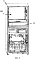
- FIG. 1 is a schematic structural diagram of a refrigerator 100 according to an embodiment of the present invention.
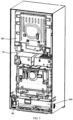
- FIG. 2 is a partially schematic structural diagram of the refrigerator 100 according to an embodiment of the present invention.
- FIG. 3 is a schematic structural diagram of the structure shown in FIG. 2 from another perspective.
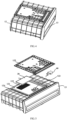
- FIG. 4 is a schematic structural diagram of a sealed drawer 11 in the refrigerator 100 according to an embodiment of the present invention.
- FIG. 5 is a schematic exploded view of the sealed drawer 11 shown in FIG. 4 .
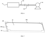
- FIG. 6 is a schematic structural diagram in which the sealed drawer 11 is connected with an air pump 41 in the refrigerator according to a further embodiment of the present invention.
- the refrigerator 100 comprises a refrigerator body 10, a door body, an air-conditioning membrane assembly 30 and an air pump assembly 40.
- the refrigerator body 10 defines a storage space 102 and a compressor chamber 103 therein.
- the number and structure of the storage space 102 may be configured as needed.
- FIG. 1 shows a case where a first space, a second space and a third space are arranged vertically in sequence.
- the storage spaces may be configured as a refrigerating space, a freezing space, a temperature changing space or a freshness-keeping space according to different purposes.
- Each storage space may be divided into a plurality of storage areas by partition plates, and articles may be stored using shelves or drawers.
- a storage container is arranged in the storage space of this embodiment, and defines the freshness-keeping space therein.
- the storage container may be a sealed drawer 11 that defines the freshness-keeping space.
- said freshness-keeping space may also be defined by a sealed case, a sealed can, a sealed box, or the like.
- the door body is arranged on the front surface of the refrigerator body 10 to close the storage space 102.
- the door body may correspond to the storage space, that is, each storage space corresponds to one or more door bodies.
- the number of the storage spaces or door bodies and the functions of the storage spaces may be actually selected according to specific conditions.
- the refrigerator 100 of this embodiment is provided with a first door body 21, a second door body 22 and a third door body 23 respectively corresponding to the first space, the second space and the third space which are arranged vertically in sequence.
- the door body may be pivotally arranged on the front surface of the refrigerator body, or may be opened as well in a drawer form to realize a drawer type storage space.
- the drawer type storage space is often provided with metal slides to ensure gentle opening and closing of the drawer and to reduce the noise.
- the first space of the refrigerator 100 of this embodiment may be opened in a pivoting manner.
- the second space and the third space may be opened in a drawer form respectively.
- An air-conditioning membrane assembly 30 is provided with at least one air-conditioning membrane and an oxygen-rich gas collection chamber, and configured to allow more oxygen than nitrogen in airflow in the surrounding space of the air-conditioning membrane assembly 30 to pass through the air-conditioning membrane and enter the oxygen-rich gas collection chamber.
- the air-conditioning membrane assembly 30 is mounted to the storage container, and the surrounding space of the air-conditioning membrane assembly is communicated with the freshness-keeping space.
- the air-conditioning membrane assembly 30 may be mounted to the sealed drawer 11.
- the air pump assembly 40 is arranged in the compressor chamber 103 and comprises an air pump 41. Since the oxygen-rich gas collection chamber is arranged in the sealed drawer 11, and FIG. 6 shows a schematic diagram in which the air pump 41 is connected with the sealed drawer 11, the air pump 41 is substantially communicated with the oxygen-rich gas collection chamber arranged in the sealed drawer 11. An inlet end of the air pump 41 is communicated with the oxygen-rich gas collection chamber in a controlled manner via a pipeline 51 and a pipeline switching mechanism 52 to pump gas in the oxygen-rich gas collection chamber to the outside of the freshness-keeping space, such that the actual content of oxygen in the freshness-keeping space is in a range of 2% to 19%.
- a gas in the oxygen-rich gas collection chamber is generally an oxygen-rich gas.
- the gas is then exhausted out of the freshness-keeping space to reduce the content of oxygen in the freshness-keeping space, such that the oxygen content is caused to be equal to or less than 19%.
- the refrigerator 100 further comprises an oxygen sensor arranged in the freshness-keeping space to monitor the actual content of oxygen in the freshness-keeping space.
- the air pump assembly 40 is further configured to drive the pipeline switching mechanism 52 to communicate the pipeline from the inlet end of the air pump 41 to the freshness-keeping space when the actual content of oxygen in the freshness-keeping space is greater than 19%, and control the air pump 41 to operate to pump the gas in the oxygen-rich gas collection chamber to the outside of the freshness-keeping space, such that the content of oxygen in the freshness-keeping space is in a range of 2% to 19%.
- the oxygen content range of 2% to 19% may be refined, such that the gas atmosphere in the freshness-keeping space can meet the freshness-keeping needs of different kinds of food.
- the pipeline switching mechanism 52 may close the pipeline from the inlet end of the air pump 41 to the freshness-keeping space, and the air pump 41 stops operating as well.
- the freshness-keeping lives of various foods will be different depending on the difference in the content of oxygen in the freshness-keeping space, in the case of other storage conditions being the same.
- the content of oxygen in the freshness-keeping space is in a range of 2% to 19%, which is a generally suitable range for air-conditioning freshness-keeping of all kinds of food.
- the freshness-keeping time of an apple is 12 days; the freshness-keeping time of grapes is 4 days; the freshness-keeping time of a baby cabbage is 13 days; the freshness-keeping time of broccoli is 14 days; the freshness-keeping time of a radish is 20 days; the freshness-keeping time of fresh lentinus edodes is 4 days; the freshness-keeping time of lychee is 7 days; the freshness-keeping time of a kiwifruit is 8 days; the freshness-keeping time of a strawberry is 4 day; and the freshness-keeping time of salmon is 3 days.
- the freshness-keeping time of an apple is 50 days; the freshness-keeping time of grapes is 18 days; the freshness-keeping time of a baby cabbage is 36 days; the freshness-keeping time of broccoli is 40 days; the freshness-keeping time of a radish is 90 days; the freshness-keeping time of fresh lentinus edodes is 15 days; the freshness-keeping time of lychee is 27 days; the freshness-keeping time of a kiwifruit is 37 days; the freshness-keeping time of a strawberry is 21 days; and the freshness-keeping time of salmon is 30 days.
- the freshness-keeping time of each of various foods is far longer than that in the case of the oxygen content of 21%.
- the content of oxygen in the freshness-keeping space is in a range of 2% to 19%, it is possible to effectively reduce the aerobic respiration intensity of food in the freshness-keeping space while the basic respiration effect of the food is ensured, and avoid the anaerobic respiration of the food, thereby ensuring the freshness-keeping effect of the food and extend the shelf life of the food.
- it is possible to assist in improving the freshness-keeping effect of the food by keeping the temperature in the freshness-keeping space within a certain range. Different food may correspond to different suitable storage temperatures.
- a refrigerating temperature of vegetables is generally 2°C to 8°C
- a refrigerating temperature of cold fresh meat is generally -2°C to 1°C
- a freezing temperature of various foods is generally -22°C to -14°C.
- the freshness-keeping effects of various foods may be improved effectively by enabling the actual content of oxygen in the freshness-keeping space to be in a range of 2% to 19%, and by keeping the temperature in the freshness-keeping space in a suitable storage temperature range for various foods.
- the air as original intake air in the freshness-keeping space, has an oxygen content of about 21%.
- an oxygen-rich gas in the oxygen-rich gas collection chamber in the freshness-keeping space is exhausted through the air-conditioning membrane assembly 30 and the air pump 40, such that the content of oxygen in the freshness-keeping space is reduced to 19% or less.
- the gas beneficial to freshness-keeping of the food may be carbon dioxide which may inhibit the aerobic respiration process of fruits and vegetables, inhibit the processes of degradation of pectin substances and chlorophyll, etc., thereby delaying the maturity of food.
- the gas maturity to freshness-keeping of the food may also be nitric oxide which may regulate cell apoptosis, affect the metabolism of endogenous ethylene in vegetables and regulate the respiratory intensity of leaf stomata, thereby playing an important role in preventing the decay of food. It should be noted that the use of normal air as the original intake air in this embodiment is not intended to limit the present invention.
- gas components in the freshness-keeping space may be different from those of the normal air, but it is also possible to reduce the actual content of oxygen in the freshness-keeping space by pumping an oxygen-rich gas by the air-conditioning membrane assembly 30 and the air pump 40, and by filling the freshness-keeping space with an inert gas or a gas beneficial to freshness-keeping of food.
- the refrigerator body 10 may comprise a cabinet 101 defining the freshness-keeping space 102 therein.
- the sealed drawer 11 comprises a drawer cylinder 12 which has a forward opening, is fixed to the cabinet 101 and defines the freshness-keeping space therein; and a drawer body 13 slidably mounted in the drawer cylinder 12, so as to be operatively withdrawn from and inserted into the drawer cylinder via the forward opening of the drawer cylinder 12.
- the drawer cylinder 12 may be arranged on the lower part of the cabinet. In other embodiments, the drawer cylinder 12 may be arranged on the middle part or the upper part of the cabinet as well.
- the cabinet 101 and the drawer cylinder 12 may be formed integrally, or may be formed separately and then mounted together.
- a plurality of air pressure balance holes may be formed in the drawer cylinder 12 to communicate the storage space 102 to the freshness-keeping space.
- Each of the air pressure balance holes may be a hole of a millimeter order.
- each of the air pressure balance holes may have a diameter of 0.1 mm to 3 mm. It is possible to balance pressures inside and outside the freshness-keeping space by providing a plurality of air pressure balance holes.
- the arrangement of the plurality of air pressure balance holes may not cause the gas in the freshness-keeping space to flow towards a larger storage space (or flow slightly or even negligibly if any), without affecting the preservation of food in the freshness-keeping space.
- the air pressure balance holes may not be formed in the drawer cylinder 12.
- the air-conditioning membrane assembly 30 is mounted to the storage container, and the surrounding space of the air-conditioning membrane assembly 30 is communicated with the freshness-keeping space.
- the air-conditioning membrane assembly 30 may be mounted to the sealed drawer 11.
- the air-conditioning membrane assembly 30 may be arranged on the drawer cylinder 12, and preferably arranged on the top wall of the drawer cylinder 12.
- an accommodating chamber 12 which is communicated with the freshness-keeping space is arranged inside a top wall of the drawer cylinder 12 to accommodate the air-conditioning membrane assembly 30.
- At least one first vent hole 122 and at least one second vent hole 123 spaced apart from the at least one first vent hole 122 are respectively formed in a wall surface between the accommodating chamber 121 in the top wall of the drawer cylinder 12 and the freshness-keeping space, to communicate the accommodating chamber 121 to the freshness-keeping space at different positions respectively.
- the first vent hole 122 and the second vent hole 123 are both small holes, and may be plural in number.
- the inside of the top wall of the drawer cylinder 12 has a recessed groove.
- the air-conditioning membrane assembly 30 is arranged in the recessed groove of the top wall of the drawer cylinder 12.
- the refrigerator 100 may further include a fan 60 arranged in the accommodating chamber 121, to drive the gas in the freshness-keeping space to flow through the at least one first vent hole 122, the accommodating chamber 121 and the at least one second vent hole123 in sequence and then return to the freshness-keeping space.
- the fan 60 is preferably a centrifugal fan arranged at the first vent hole 122 in the accommodating chamber 121. That is, the centrifugal fan is located above the at least one first vent hole 122, and keeps an axis of rotation vertically downward. An air inlet of the centrifugal fan directly faces the first vent hole 122.
- An air outlet of the centrifugal fan may face the air-conditioning membrane assembly 30.
- the air-conditioning membrane assembly 30 is arranged above the at least one second vent hole 123, such that each of the air-conditioning membranes of the air-conditioning membrane assembly 30 is parallel to the top wall of the drawer cylinder 12.
- At least one first vent hole 122 is formed in the front part of the top wall, and at least one second vent hole 123 is formed in the rear part of the top wall. That is, the centrifugal fan is arranged at the front part of the accommodating chamber 121, and the air-conditioning membrane assembly 30 is arranged at the rear part of the accommodating chamber 121.
- the top wall of the drawer cylinder 12 comprises a lower plate portion 124 and a cover plate portion 125.
- a recessed portion is formed in a partial area of the lower plate portion 124.
- the cover plate portion 125 detachably covers the recessed portion to form the accommodating chamber 121.
- the lower plate portion 124 may be integrally formed with the side wall, the bottom wall, and the rear wall of the drawer cylinder 12.
- FIG. 7 is a schematic structural diagram of the air-conditioning membrane assembly in the refrigerator 100 according to an embodiment of the present invention.
- FIG. 8 is a schematic exploded view of the air-conditioning membrane assembly shown in FIG. 7 .
- FIG. 9 is a schematic structural diagram of a support frame in the air-conditioning membrane assembly shown in FIG. 8 .
- FIG. 10 is a schematic structural diagram of the support frame in the air-conditioning membrane assembly shown in FIG. 8 as observed from another perspective.
- the air-conditioning membrane is an oxygen-rich membrane
- the air-conditioning membrane assembly 30 may be an oxygen-rich membrane assembly 31.
- the oxygen-rich membrane assembly 31 of this embodiment may generally comprise a support frame 32 and an oxygen-rich membrane 33 arranged on the support frame 32.
- the oxygen-rich membrane 33 is permeable to all gases, except that different gases have different degrees of permeation.
- Gas permeation through the oxygen-rich membrane 33 is a complex process.
- the permeation mechanism of this process generally resides in that gas molecules are first adsorbed to the surface of the oxygen-rich membrane 33 and dissolved, then diffused in the oxygen-rich membrane 33, and finally desorbed from the other side of the oxygen-rich membrane 33.
- the oxygen-rich membrane separation technique realizes gas separation depending on the difference in dissolution and diffusion coefficients of different gases in the oxygen-rich membrane 33.
- gases such as oxygen, hydrogen, helium, hydrogen sulfide, carbon dioxide and the like which have relatively high permeation rates penetrate through the oxygen-rich membrane 33, and are then enriched on the permeation side of the oxygen-rich membrane 33.
- gases, such as nitrogen, carbon monoxide and the like which have relatively low permeation rates are retained on the retention side of the oxygen-rich membrane 33 and are then enriched. Therefore, the purpose of separation of the mixed gas is achieved.
- the support frame 32 has a first surface 321 and a second surface 322 parallel to each other.
- a plurality of airflow passages 323 which extends on the first surface 321 and the second surface 322 respectively and penetrates through the support frame 32 to communicate the first surface 321 to the second surface 322 are formed on the support frame 32.
- the plurality of airflow passages 323 jointly forms the oxygen-rich gas collection chamber.
- At least one oxygen-rich membrane 33 may be arranged in the present embodiment.
- two planar oxygen-rich membranes may be arranged, and are laid on the first surface 321 and the second surface 322 of the support frame 32 respectively.
- the oxygen-rich membrane 33 may allow oxygen in air outside thereof to pass through the oxygen-rich membrane 33 into the oxygen-rich gas collection chamber, to form an oxygen-rich gas, such that the air outside the oxygen-rich membrane becomes a nitrogen-rich gas.
- the support frame 32 comprises a suction hole 324 that is communicated with at least one of the plurality of airflow passages 323, to allow the oxygen-rich gas in the oxygen-rich gas collection chamber to be sucked out by the air pump 41.
- the oxygen-rich gas collection chamber is in a negative pressure state. Therefore, oxygen in air outside the oxygen-rich membrane assembly 31 will continue to pass through the oxygen-rich membrane 33 into the oxygen-rich gas collection chamber, such that the air outside the oxygen-rich membrane assembly 31 forms a nitrogen-rich atmosphere.
- the plurality of airflow passages 323 formed inside the support frame 32 may be a plurality of cavities that is communicated with the suction hole 324.
- FIGS. 8 and 9 for further ease of installation, it is possible to pre-fasten the oxygen-rich membrane 33 in a mounting groove 327 of the support frame 32 by using a circle of double-sided adhesive tape 325, and then fill a loop slot 328 of the support frame 32 with a circle of sealing adhesive 326, such that the oxygen-rich membrane 33 is mounted in the mounting groove 327 of the support frame 32 in a sealed manner.
- the inlet end of the air pump 41 is communicated with the oxygen-rich gas collection chamber in the freshness-keeping space via the pipeline 51 and the pipeline switching mechanism 52, and concretely, may be communicated with the suction hole 324.
- the air pump 41 is configured to suck air outwards through the suction hole 324, such that the pressure in the oxygen-rich gas collection chamber is lower than the pressure of the freshness-keeping space. That is to say, as the air pump 41 sucks air outwards, the air in the freshness-keeping space may flow to the oxygen-rich membrane assembly.
- oxygen-rich membrane assembly Under the action of the oxygen-rich membrane assembly, some or all of oxygen in the air in the freshness-keeping space enters the oxygen-rich gas collection chamber and is then exhausted out of the freshness-keeping space through the pipeline 51 and the air pump 41, such that a gas atmosphere which is rich in nitrogen and deficient in oxygen to facilitate the freshness-keeping of food may be obtained in the freshness-keeping space.
- FIG. 11 is a schematic exploded view of an air pump assembly 40 in the refrigerator 100 according to the present invention.
- the air pump assembly 40 further comprises a mounting base plate 42 and a sealed case 43.
- the mounting base plate 42 is mounted to the bottom surface of the compressor chamber 103 through a plurality of damping foot pads 44.
- the sealed case 43 is mounted to the mounting base plate 42.
- the air pump 41 is mounted in the sealed case 43. That is, the air pump 41 is arranged inside the sealed case 43, and the sealed case 43 is mounted in the compressor chamber 103 through the mounting base plate 42.
- the sealed case 43 may greatly prevent noise and/or waste heat from propagating outwards.
- a plurality of damping foot pads 44 may also be mounted on the mounting base plate 42.
- the number of the damping foot pads 44 may be preferably four.
- the four damping foot pads 44 are mounted in foot pad mounting holes formed in four corners of the mounting base plate 42.
- a mounting frame is arranged inside the sealed case 43.
- the mounting frame is connected to the inner wall of the sealed case 43 by a plurality of damping blocks.
- the air pump 41 is fixed inside the mounting frame, so as to reduce the vibration and noise when the air pump 41 is in operation.
- the bottom of the mounting frame is provided with two damping blocks which is sleeved on positioning posts on the bottom surface of the sealed case 43.
- One circular damping block is arranged on each of two opposite sides of the mounting frame, and is clamped in a clamping slot of the corresponding side wall of the sealed case 43.
- One damping block is fixed to each of the other two opposite sides of the mounting frame.
- the air pump 41 may be located between the respective damping blocks in the sealed case 43 and fastened to the mounting frame by screws.
- a refrigeration system of the refrigerator 100 may be a refrigeration cycle system composed of a compressor, a condenser, a throttle device, an evaporator, and the like.
- the compressor is mounted in the compressor chamber 103.
- the evaporator is configured to supply a cooling capacity directly or indirectly into the storage space 102.
- the evaporator may be arranged on the outside or inside of the rear wall surface of the cabinet.
- the refrigerator 10 further has an evaporator chamber inside.
- the evaporator chamber is communicated with the storage space 102 through an air passage system.
- an evaporator is arranged inside the evaporator chamber.
- a fan is arranged at an outlet of the evaporator chamber to perform circulation cooling for the storage space 102.
- the air pump 41 is arranged at one end of the compressor chamber 103, and the compressor may be arranged at the other end of the compressor chamber 103, such that the air pump 41 is away from the compressor, thereby reducing nose superposition and waste heat superposition.
- the air pump 41 may be arranged at one end, adjacent to the pivoting side of the door body, of the compressor chamber 103.
- the air pump 41 may be arranged at either end of the compressor chamber 103.
- the air pump 41 is arranged adjacent to the compressor.
- the air pump 41 is arranged at one end of the compressor chamber 103, and located between the compressor and the side wall of the compressor chamber 103.
- the air pump 41 is arranged in the compressor chamber 103, and can fully make use of the space in the compressor chamber, without occupying other places additionally, such that the volume of the refrigerator may not be additionally increased, and the structure of the refrigerator can be made compact.
- the air-conditioning membrane assembly allows more oxygen than the nitrogen in the freshness-keeping space to pass through the air-conditioning membrane to enter the oxygen-rich gas collection chamber, and the gas in the oxygen-rich gas collection chamber is pumped to the outside of the freshness-keeping space through the air pump 41, such that the actual content of oxygen in the freshness-keeping space is in a range of 2% to 19%.
- This oxygen content range is a suitable interval for air-conditioning freshness-keeping of foodtuff, such that the content of oxygen in the freshness-keeping space is in the above-mentioned range, which can effectively reduce the aerobic respiration intensity of the food while ensuring the basic respiration function, and avoid the anaerobic respiration of the food. Therefore, the storage effect of the foodtuff is improved, and the shelf life of the food is prolonged.
- the oxygen sensor is arranged in the freshness-keeping space to monitor the actual content of oxygen in the freshness-keeping space.
- the oxygen content is used as an air-regulating standard, and a communication state between the air pump 41 and the oxygen-rich gas collection chamber is switched by the pipeline switching mechanism, to ensure that the actual content of oxygen in the freshness-keeping space is in a range of 2% to 19%, thereby ensuring the freshness-keeping effect of the food.
- the air pump assembly 40 is arranged in the compressor chamber 103, without occupying other places. Therefore, the volume of the refrigerator will not be additionally increased, and the structure of the refrigerator can be made compact.
Landscapes
- Engineering & Computer Science (AREA)
- Chemical & Material Sciences (AREA)
- Combustion & Propulsion (AREA)
- Physics & Mathematics (AREA)
- Mechanical Engineering (AREA)
- Thermal Sciences (AREA)
- General Engineering & Computer Science (AREA)
- Organic Chemistry (AREA)
- Life Sciences & Earth Sciences (AREA)
- Analytical Chemistry (AREA)
- Inorganic Chemistry (AREA)
- Wood Science & Technology (AREA)
- Zoology (AREA)
- Food Science & Technology (AREA)
- Polymers & Plastics (AREA)
- Cold Air Circulating Systems And Constructional Details In Refrigerators (AREA)
- General Chemical & Material Sciences (AREA)
- Oil, Petroleum & Natural Gas (AREA)
- Chemical Kinetics & Catalysis (AREA)
Claims (11)
- Kühlschrank, aufweisend:einen Kühlschrankkörper (10), einen Türkörper, eine Klimamembrananordnung und eine Luftpumpenanordnung, wobei der Kühlschrankkörper einen Lagerraum (102) und eine Kompressorkammer darin ausbildet, ein Lagerbehälter in dem Lagerraum (102) angeordnet ist und ein Frischehalteraum innerhalb des Lagerbehälters ausgebildet ist;der Türkörper an der vorderen Oberfläche des Kühlschrankkörpers angeordnet ist, um den Lagerraum zu schließen;die Klimamembrananordnung (30) an dem Lagerbehälter angebracht ist und der umgebende Raum der Klimamembrananordnung mit dem Frischehalteraum in Verbindung steht, wobei die Klimamembrananordnung mindestens eine Klimamembran und eine sauerstoffreiche Gassammelkammer aufweist und ausgebildet ist, um zu ermöglichen, dass mehr Sauerstoff als Stickstoff in einem Luftstrom in einem umgebenden Raum der Klimamembrananordnung (30) durch die Klimamembran hindurchdringt und in die sauerstoffreiche Gassammelkammer eintritt;die Luftpumpenanordnung innerhalb der Kompressorkammer angeordnet ist und die Luftpumpenanordnung eine Luftpumpe aufweist, wobei ein Einlassende der Luftpumpe mit der sauerstoffreichen Gassammelkammer in einer gesteuerten Weise über eine Rohrleitung und einen Rohrleitungsschaltmechanismus zum Pumpen von Gas in der sauerstoffreichen Gassammelkammer zu der Außenseite des Frischehalteraums in Verbindung steht, so dass der tatsächliche Gehalt an Sauerstoff in dem Frischehalteraum in einem Bereich von 2 % bis 19 % liegt;dadurch gekennzeichnet, dass die Luftpumpenanordnung (40) ferner aufweist:eine Befestigungsgrundplatte (42), die an der unteren Oberfläche der Kompressorkammer (103) über eine Mehrzahl von dämpfenden Fußunterlagen (44) angebracht ist; undein abgedichtetes Gehäuse (43), das an der Befestigungsgrundplatte (42) angebracht ist, wobei die Luftpumpe (41) in dem abgedichteten Gehäuse (43) angebracht ist.
- Kühlschrank nach Anspruch 1, wobeieine Aufnahmekammer (121), die mit dem Frischehalteraum in Verbindung steht, um die Klimamembrananordnung (30) aufzunehmen, undmindestens ein erstes Lüftungsloch (122) und mindestens ein zweites Lüftungsloch (123), das von dem mindestens einen ersten Lüftungsloch (122) beabstandet ist, jeweils in einer Wandoberfläche zwischen der Aufnahmekammer und dem Frischehalteraum ausgebildet sind, um die Aufnahmekammer (121) mit dem Frischehalteraum jeweils an unterschiedlichen Positionen zu verbinden;der Kühlschrank ferner ein Gebläse (60) aufweist, das in der Aufnahmekammer (121) angeordnet ist, um das Gas in dem Frischehalteraum anzutreiben, um nacheinander durch das mindestens eine erste Lüftungsloch (122), die Aufnahmekammer (121) und das mindestens eine zweite Lüftungsloch (123) zu strömen und dann zu dem Frischehalteraum zurückzukehren.
- Kühlschrank nach Anspruch 2, wobei der Kühlschrankkörper einen Schrank (101) aufweist, der den Lagerraum (102) darin ausbildet, der Lagerbehälter als eine abgedichtete Schublade ausgebildet ist, die den Frischehalteraum ausbildet, die Luftpumpe (41) im Wesentlichen mit der sauerstoffreichen Gassammelkammer in Verbindung steht, die in der abgedichteten Schublade angeordnet ist, wobei die abgedichtete Schublade aufweist:einen Schubladenzylinder (12), der eine vordere Öffnung aufweist und an dem Schrank befestigt ist; undeinen Schubladenkörper (13), der verschiebbar in dem Schubladenzylinder (12) angebracht ist, um über die vordere Öffnung des Schubladenzylinders (12) betriebsmäßig aus dem Schubladenzylinder (12) herausgezogen und in diesen eingesetzt zu werden.
- Kühlschrank nach Anspruch 3, wobei
die Aufnahmekammer (121) innerhalb einer oberen Wand des Schubladenzylinders (12) angeordnet ist. - Kühlschrank nach Anspruch 1, wobeidie Luftpumpe (41) an einem Ende der Kompressorkammer (103) angeordnet ist, der Kompressor an dem anderen Ende der Kompressorkammer angeordnet ist;ein Befestigungsrahmen innerhalb des abgedichteten Gehäuses (43) angeordnet ist, der Befestigungsrahmen mit der Innenwand des abgedichteten Gehäuses (43) durch eine Mehrzahl von Dämpfungsblöcken verbunden ist, und die Luftpumpe (41) innerhalb des Befestigungsrahmens befestigt ist.
- Kühlschrank nach Anspruch 3, wobei eine Mehrzahl von Luftdruckausgleichslöchern in dem Schubladenzylinder (12) ausgebildet ist, um den Lagerraum (102) mit dem Frischehalteraum in Verbindung zu bringen, wobei jedes der Mehrzahl von Luftdruckausgleichslöchern als ein Loch einer Millimeterordnung ausgebildet ist.
- Kühlschrank nach Anspruch 3, wobei die obere Wand des Schubladenzylinders (12) einen unteren Plattenabschnitt (124) und einen Abdeckplattenabschnitt (125) aufweist, ein vertiefter Abschnitt in einem Teilbereich des unteren Plattenabschnitts (124) ausgebildet ist, und der Abdeckplattenabschnitt (125) den vertieften Abschnitt lösbar abdeckt, um die Aufnahmekammer (121) zu bilden.
- Kühlschrank nach Anspruch 3, wobeidas Gebläse (60) als ein Zentrifugalgebläse konfiguriert ist, das über dem mindestens einen ersten Lüftungsloch (122) mit einer Drehachse des Zentrifugalgebläses vertikal nach unten angeordnet ist, ein Lufteinlass des Zentrifugalgebläses direkt dem mindestens einen ersten Lüftungsloch (122) zugewandt ist und ein Luftauslass des Zentrifugalgebläses der Klimamembrananordnung (30) zugewandt ist; unddie Klimamembrananordnung (30) über dem mindestens einen zweiten Lüftungsloch (123) angeordnet ist, so dass jede der Klimamembranen der Klimamembrananordnung (30) parallel zu der oberen Wand des Schubladenzylinders (12) ist.
- Kühlschrank nach Anspruch 1, ferner aufweisend einen Sauerstoffsensor, der in dem Frischehalteraum angeordnet ist, um den Gehalt an Sauerstoff in dem Frischehalteraum zu überwachen, wobei die Rohrleitung von dem Einlassende der Luftpumpe (41) mit dem Frischehalteraum kommuniziert, wenn der Gehalt an Sauerstoff in dem Frischehalteraum größer als 19 % ist, und die Luftpumpe betrieben wird, um das Gas in der sauerstoffreichen Gassammelkammer zu der Außenseite des Frischehalteraums zu pumpen.
- Kühlschrank nach Anspruch 1, wobei die sauerstoffreiche Membrananordnung (31) ferner aufweist:einen Stützrahmen (32) mit einer ersten Oberfläche (321) und einer zweiten Oberfläche (322), die parallel zueinander angeordnet sind, wobei eine Mehrzahl von Luftstromdurchlässen (323) an dem Stützrahmen (32) ausgebildet ist, die sich jeweils an der ersten Oberfläche (321) und der zweiten Oberfläche (322) erstreckt und durch den Stützrahmen (32) hindurchdringt, um die erste Oberfläche (321) und die zweite Oberfläche (322) zu verbinden; die Mehrzahl von Luftstromdurchlässen (323) zusammen die sauerstoffreiche Gassammelkammer ausbildet;die mindestens eine sauerstoffreiche Membran als zwei ebene sauerstoffreiche Membranen ausgebildet ist, die jeweils an der ersten Oberfläche (321) und der zweiten Oberfläche (322) des Stützrahmens (32) angeordnet sind; undder Stützrahmen (32) ein Saugloch (324) aufweist, das mit mindestens einem der Mehrzahl von Luftstromdurchlässen (323) in Verbindung steht, um zu ermöglichen, dass das sauerstoffreiche Gas in der sauerstoffreichen Gassammelkammer durch die Luftpumpe (41) abgesaugt wird.
- Kühlschrank nach Anspruch 10, wobei die sauerstoffreiche Membran in einer Befestigungsnut (327) des Stützrahmens (32) unter Verwendung eines Kreises eines doppelseitigen Klebebandes (325) befestigt ist, und ein Kreis eines Dichtungsklebers (326) in eine Schleifennut (328) des Stützrahmens (32) gefüllt ist.
Applications Claiming Priority (3)
| Application Number | Priority Date | Filing Date | Title |
|---|---|---|---|
| CN201611110816.5A CN106766565B (zh) | 2016-12-02 | 2016-12-02 | 冰箱 |
| EP17875485.9A EP3550233B1 (de) | 2016-12-02 | 2017-11-28 | Kühlschrank |
| PCT/CN2017/113372 WO2018099374A1 (zh) | 2016-12-02 | 2017-11-28 | 冰箱 |
Related Parent Applications (2)
| Application Number | Title | Priority Date | Filing Date |
|---|---|---|---|
| EP17875485.9A Division EP3550233B1 (de) | 2016-12-02 | 2017-11-28 | Kühlschrank |
| EP17875485.9A Division-Into EP3550233B1 (de) | 2016-12-02 | 2017-11-28 | Kühlschrank |
Publications (3)
| Publication Number | Publication Date |
|---|---|
| EP3699518A1 EP3699518A1 (de) | 2020-08-26 |
| EP3699518B1 true EP3699518B1 (de) | 2025-05-14 |
| EP3699518C0 EP3699518C0 (de) | 2025-05-14 |
Family
ID=58879223
Family Applications (2)
| Application Number | Title | Priority Date | Filing Date |
|---|---|---|---|
| EP19201726.7A Active EP3699518B1 (de) | 2016-12-02 | 2017-11-28 | Kühlschrank |
| EP17875485.9A Active EP3550233B1 (de) | 2016-12-02 | 2017-11-28 | Kühlschrank |
Family Applications After (1)
| Application Number | Title | Priority Date | Filing Date |
|---|---|---|---|
| EP17875485.9A Active EP3550233B1 (de) | 2016-12-02 | 2017-11-28 | Kühlschrank |
Country Status (7)
| Country | Link |
|---|---|
| US (2) | US11147298B2 (de) |
| EP (2) | EP3699518B1 (de) |
| CN (1) | CN106766565B (de) |
| AU (2) | AU2017370236B2 (de) |
| NZ (1) | NZ757743A (de) |
| RU (2) | RU2733617C2 (de) |
| WO (1) | WO2018099374A1 (de) |
Families Citing this family (11)
| Publication number | Priority date | Publication date | Assignee | Title |
|---|---|---|---|---|
| CN106705536B (zh) * | 2016-12-02 | 2020-08-28 | 青岛海尔股份有限公司 | 冰箱 |
| CN106766565B (zh) | 2016-12-02 | 2020-08-28 | 青岛海尔股份有限公司 | 冰箱 |
| CN106628640B (zh) * | 2016-12-02 | 2019-01-18 | 青岛海尔股份有限公司 | 气调保鲜储物装置 |
| CN108759243A (zh) * | 2018-06-19 | 2018-11-06 | 青岛海尔股份有限公司 | 控氧保鲜冰箱 |
| CN108759244A (zh) * | 2018-06-19 | 2018-11-06 | 青岛海尔股份有限公司 | 具有控氧保鲜功能的冰箱 |
| CN109186160A (zh) * | 2018-08-28 | 2019-01-11 | 安徽康佳同创电器有限公司 | 一种密封保鲜冰箱 |
| CN111442603B (zh) * | 2020-04-20 | 2024-04-12 | 珠海格力电器股份有限公司 | 一种气调保鲜装置、冰箱及其气调保鲜方法 |
| CN113124611B (zh) * | 2021-04-28 | 2022-03-04 | 珠海格力电器股份有限公司 | 一种冰箱的气调控制方法、气调抽屉及保鲜冰箱 |
| CN113137813B (zh) * | 2021-04-28 | 2022-05-10 | 珠海格力电器股份有限公司 | 一种冰箱的气体浓度调控方法及保鲜冰箱 |
| CN113137803B (zh) * | 2021-04-28 | 2022-08-26 | 珠海格力电器股份有限公司 | 一种冰箱的分区气调方法及冰箱 |
| CN117213150A (zh) * | 2023-10-26 | 2023-12-12 | 珠海格力电器股份有限公司 | 一种保鲜间室、冰箱及控制方法 |
Family Cites Families (35)
| Publication number | Priority date | Publication date | Assignee | Title |
|---|---|---|---|---|
| US4961322A (en) * | 1987-12-28 | 1990-10-09 | Aisin Seiki Kabushiki Kuisha | Fresh food storing device |
| JPH043875A (ja) * | 1990-04-18 | 1992-01-08 | Mitsubishi Electric Corp | 冷蔵庫 |
| JPH055585A (ja) * | 1991-06-28 | 1993-01-14 | Sharp Corp | 新鮮貯蔵庫 |
| JPH05227881A (ja) * | 1992-02-19 | 1993-09-07 | Matsushita Refrig Co Ltd | 保存庫 |
| JPH0618152A (ja) * | 1992-07-03 | 1994-01-25 | Toshiba Corp | 冷蔵庫 |
| NZ250904A (en) * | 1994-02-17 | 1997-06-24 | Transphere Systems Ltd | Controlled atmosphere storage: produce stored on pallets in refrigerated container, each pallet having its own controlled atmosphere. |
| JPH09287869A (ja) * | 1996-04-18 | 1997-11-04 | Matsushita Electric Ind Co Ltd | 酸素濃度調整機能付き冷蔵庫 |
| FR2780618B1 (fr) * | 1998-07-03 | 2000-08-04 | Air Liquide | Procede pour minimiser l'oxydation des produits alimentaires |
| US20040031705A1 (en) * | 2002-06-17 | 2004-02-19 | Detemple Thomas E. | Atmospheric controlled container |
| US20040033162A1 (en) * | 2002-08-16 | 2004-02-19 | Lawrence Kunstadt | Storage device utilizing zeolites to control gaseous content |
| JP2004093026A (ja) * | 2002-08-30 | 2004-03-25 | Toshiba Corp | 冷蔵庫 |
| CN2608114Y (zh) * | 2003-04-10 | 2004-03-31 | 海尔科化工程塑料国家工程研究中心股份有限公司 | 一种平板式富氧膜组件 |
| JP2004360948A (ja) * | 2003-06-03 | 2004-12-24 | Sanyo Electric Co Ltd | 冷蔵庫 |
| KR20050088742A (ko) | 2004-03-03 | 2005-09-07 | 크린에어테크놀로지 주식회사 | 산소발생기 겸용 저장고 |
| JP2005257208A (ja) | 2004-03-12 | 2005-09-22 | Toshiba Corp | 冷蔵庫 |
| CN2697545Y (zh) * | 2004-04-05 | 2005-05-04 | 声宝股份有限公司 | 改良的冰箱保鲜结构 |
| JP2005300004A (ja) | 2004-04-09 | 2005-10-27 | Toshiba Corp | 冷蔵庫 |
| JP2007015210A (ja) | 2005-07-07 | 2007-01-25 | Mitsubishi Plastics Ind Ltd | 食品包装用ストレッチシュリンクフィルム |
| WO2007020581A1 (en) * | 2005-08-12 | 2007-02-22 | Arcelik Anonim Sirketi | A cooling device |
| ITMI20051789A1 (it) * | 2005-09-27 | 2007-03-28 | Finanziaria Unterland S P A | Impianto frigorifero di conservazione particolarmente per uso domestico |
| CN101000191A (zh) * | 2006-01-11 | 2007-07-18 | 王冬雷 | 一种带制氮保鲜功能的冰箱、冰柜 |
| CN201199115Y (zh) * | 2008-04-10 | 2009-02-25 | 河南新飞电器有限公司 | 一种降氧气调保鲜冰箱 |
| CN201218181Y (zh) * | 2008-06-11 | 2009-04-08 | 汤建 | 微型静音气泵 |
| CN201251336Y (zh) * | 2008-07-01 | 2009-06-03 | 河南新飞电器有限公司 | 膜降氧气调保鲜冰箱 |
| US9488404B2 (en) * | 2008-09-30 | 2016-11-08 | Thermo Fisher Scientific (Asheville) Llc | Frost reduction by active circulation |
| CN101766321B (zh) * | 2008-12-30 | 2012-10-24 | 苏州三星电子有限公司 | 超长期保鲜系统 |
| KR101572716B1 (ko) * | 2012-06-29 | 2015-11-27 | 가부시끼가이샤 도시바 | 냉장고 및 산소 저감 장치 |
| JP2015072103A (ja) * | 2013-10-03 | 2015-04-16 | ダイキン工業株式会社 | コンテナ用冷凍装置 |
| JP5971296B2 (ja) * | 2014-09-16 | 2016-08-17 | ダイキン工業株式会社 | コンテナ用冷凍装置 |
| CN106766565B (zh) | 2016-12-02 | 2020-08-28 | 青岛海尔股份有限公司 | 冰箱 |
| CN206291616U (zh) * | 2016-12-02 | 2017-06-30 | 青岛海尔股份有限公司 | 冰箱 |
| CN206362069U (zh) * | 2016-12-02 | 2017-07-28 | 青岛海尔股份有限公司 | 冰箱 |
| CN206362048U (zh) | 2016-12-02 | 2017-07-28 | 青岛海尔股份有限公司 | 冰箱 |
| CN107044752B (zh) | 2016-12-02 | 2019-12-24 | 青岛海尔股份有限公司 | 冰箱 |
| CN106705536B (zh) * | 2016-12-02 | 2020-08-28 | 青岛海尔股份有限公司 | 冰箱 |
-
2016
- 2016-12-02 CN CN201611110816.5A patent/CN106766565B/zh active Active
-
2017
- 2017-11-28 AU AU2017370236A patent/AU2017370236B2/en active Active
- 2017-11-28 RU RU2019130995A patent/RU2733617C2/ru active
- 2017-11-28 RU RU2019116798A patent/RU2721527C1/ru active
- 2017-11-28 EP EP19201726.7A patent/EP3699518B1/de active Active
- 2017-11-28 NZ NZ757743A patent/NZ757743A/en unknown
- 2017-11-28 EP EP17875485.9A patent/EP3550233B1/de active Active
- 2017-11-28 US US16/466,294 patent/US11147298B2/en active Active
- 2017-11-28 WO PCT/CN2017/113372 patent/WO2018099374A1/zh not_active Ceased
-
2019
- 2019-10-01 AU AU2019240580A patent/AU2019240580B2/en active Active
- 2019-10-08 US US16/596,722 patent/US10820614B2/en active Active
Also Published As
| Publication number | Publication date |
|---|---|
| AU2019240580B2 (en) | 2021-05-06 |
| EP3699518A1 (de) | 2020-08-26 |
| US20200037640A1 (en) | 2020-02-06 |
| AU2019240580A1 (en) | 2019-10-24 |
| EP3550233A1 (de) | 2019-10-09 |
| US11147298B2 (en) | 2021-10-19 |
| RU2019130995A (ru) | 2019-12-16 |
| WO2018099374A1 (zh) | 2018-06-07 |
| RU2019130995A3 (de) | 2020-05-13 |
| EP3550233B1 (de) | 2021-03-17 |
| AU2017370236B2 (en) | 2020-04-02 |
| NZ757743A (en) | 2021-12-24 |
| RU2733617C2 (ru) | 2020-10-05 |
| AU2017370236A1 (en) | 2019-06-13 |
| EP3550233A4 (de) | 2019-11-27 |
| RU2721527C1 (ru) | 2020-05-19 |
| CN106766565B (zh) | 2020-08-28 |
| NZ753989A (en) | 2020-12-18 |
| US20200064053A1 (en) | 2020-02-27 |
| US10820614B2 (en) | 2020-11-03 |
| EP3699518C0 (de) | 2025-05-14 |
| CN106766565A (zh) | 2017-05-31 |
Similar Documents
| Publication | Publication Date | Title |
|---|---|---|
| EP3699518B1 (de) | Kühlschrank | |
| EP3550237B1 (de) | Kühlschrank | |
| EP3550230B1 (de) | Kühl- und gefriervorrichtung | |
| CN106813443B (zh) | 冷藏冷冻设备 | |
| RU2715843C1 (ru) | Устройство разделения воздуха и холодильное и морозильное устройство | |
| CN106705536B (zh) | 冰箱 | |
| CN113639507B (zh) | 冷藏冷冻设备 | |
| CN206291616U (zh) | 冰箱 | |
| CN206362069U (zh) | 冰箱 | |
| CN206362048U (zh) | 冰箱 | |
| CN206352919U (zh) | 冷藏冷冻设备 | |
| CN206514591U (zh) | 冷藏冷冻设备 | |
| NZ753989B2 (en) | Refrigerator | |
| NZ753991B2 (en) | Refrigerator | |
| CN116447794A (zh) | 冰箱 |
Legal Events
| Date | Code | Title | Description |
|---|---|---|---|
| PUAI | Public reference made under article 153(3) epc to a published international application that has entered the european phase |
Free format text: ORIGINAL CODE: 0009012 |
|
| STAA | Information on the status of an ep patent application or granted ep patent |
Free format text: STATUS: THE APPLICATION HAS BEEN PUBLISHED |
|
| AC | Divisional application: reference to earlier application |
Ref document number: 3550233 Country of ref document: EP Kind code of ref document: P |
|
| AK | Designated contracting states |
Kind code of ref document: A1 Designated state(s): AL AT BE BG CH CY CZ DE DK EE ES FI FR GB GR HR HU IE IS IT LI LT LU LV MC MK MT NL NO PL PT RO RS SE SI SK SM TR |
|
| AX | Request for extension of the european patent |
Extension state: BA ME |
|
| STAA | Information on the status of an ep patent application or granted ep patent |
Free format text: STATUS: REQUEST FOR EXAMINATION WAS MADE |
|
| 17P | Request for examination filed |
Effective date: 20210224 |
|
| RBV | Designated contracting states (corrected) |
Designated state(s): AL AT BE BG CH CY CZ DE DK EE ES FI FR GB GR HR HU IE IS IT LI LT LU LV MC MK MT NL NO PL PT RO RS SE SI SK SM TR |
|
| STAA | Information on the status of an ep patent application or granted ep patent |
Free format text: STATUS: EXAMINATION IS IN PROGRESS |
|
| 17Q | First examination report despatched |
Effective date: 20220121 |
|
| GRAP | Despatch of communication of intention to grant a patent |
Free format text: ORIGINAL CODE: EPIDOSNIGR1 |
|
| STAA | Information on the status of an ep patent application or granted ep patent |
Free format text: STATUS: GRANT OF PATENT IS INTENDED |
|
| INTG | Intention to grant announced |
Effective date: 20241210 |
|
| GRAS | Grant fee paid |
Free format text: ORIGINAL CODE: EPIDOSNIGR3 |
|
| GRAA | (expected) grant |
Free format text: ORIGINAL CODE: 0009210 |
|
| STAA | Information on the status of an ep patent application or granted ep patent |
Free format text: STATUS: THE PATENT HAS BEEN GRANTED |
|
| RAP3 | Party data changed (applicant data changed or rights of an application transferred) |
Owner name: QINGDAO HAIER JOINT STOCK CO., LTD. |
|
| AC | Divisional application: reference to earlier application |
Ref document number: 3550233 Country of ref document: EP Kind code of ref document: P |
|
| AK | Designated contracting states |
Kind code of ref document: B1 Designated state(s): AL AT BE BG CH CY CZ DE DK EE ES FI FR GB GR HR HU IE IS IT LI LT LU LV MC MK MT NL NO PL PT RO RS SE SI SK SM TR |
|
| REG | Reference to a national code |
Ref country code: GB Ref legal event code: FG4D |
|
| REG | Reference to a national code |
Ref country code: CH Ref legal event code: EP |
|
| REG | Reference to a national code |
Ref country code: DE Ref legal event code: R096 Ref document number: 602017089512 Country of ref document: DE |
|
| REG | Reference to a national code |
Ref country code: IE Ref legal event code: FG4D |
|
| U01 | Request for unitary effect filed |
Effective date: 20250611 |
|
| U07 | Unitary effect registered |
Designated state(s): AT BE BG DE DK EE FI FR IT LT LU LV MT NL PT RO SE SI Effective date: 20250617 |
|
| PG25 | Lapsed in a contracting state [announced via postgrant information from national office to epo] |
Ref country code: ES Free format text: LAPSE BECAUSE OF FAILURE TO SUBMIT A TRANSLATION OF THE DESCRIPTION OR TO PAY THE FEE WITHIN THE PRESCRIBED TIME-LIMIT Effective date: 20250514 |
|
| PG25 | Lapsed in a contracting state [announced via postgrant information from national office to epo] |
Ref country code: NO Free format text: LAPSE BECAUSE OF FAILURE TO SUBMIT A TRANSLATION OF THE DESCRIPTION OR TO PAY THE FEE WITHIN THE PRESCRIBED TIME-LIMIT Effective date: 20250814 Ref country code: GR Free format text: LAPSE BECAUSE OF FAILURE TO SUBMIT A TRANSLATION OF THE DESCRIPTION OR TO PAY THE FEE WITHIN THE PRESCRIBED TIME-LIMIT Effective date: 20250815 |
|
| PG25 | Lapsed in a contracting state [announced via postgrant information from national office to epo] |
Ref country code: PL Free format text: LAPSE BECAUSE OF FAILURE TO SUBMIT A TRANSLATION OF THE DESCRIPTION OR TO PAY THE FEE WITHIN THE PRESCRIBED TIME-LIMIT Effective date: 20250514 |
|
| PG25 | Lapsed in a contracting state [announced via postgrant information from national office to epo] |
Ref country code: HR Free format text: LAPSE BECAUSE OF FAILURE TO SUBMIT A TRANSLATION OF THE DESCRIPTION OR TO PAY THE FEE WITHIN THE PRESCRIBED TIME-LIMIT Effective date: 20250514 |
|
| PG25 | Lapsed in a contracting state [announced via postgrant information from national office to epo] |
Ref country code: RS Free format text: LAPSE BECAUSE OF FAILURE TO SUBMIT A TRANSLATION OF THE DESCRIPTION OR TO PAY THE FEE WITHIN THE PRESCRIBED TIME-LIMIT Effective date: 20250814 |
|
| PG25 | Lapsed in a contracting state [announced via postgrant information from national office to epo] |
Ref country code: IS Free format text: LAPSE BECAUSE OF FAILURE TO SUBMIT A TRANSLATION OF THE DESCRIPTION OR TO PAY THE FEE WITHIN THE PRESCRIBED TIME-LIMIT Effective date: 20250914 |
|
| U20 | Renewal fee for the european patent with unitary effect paid |
Year of fee payment: 9 Effective date: 20251028 |