EP3699129B1 - Kartenstapler - Google Patents
Kartenstapler Download PDFInfo
- Publication number
- EP3699129B1 EP3699129B1 EP20154281.8A EP20154281A EP3699129B1 EP 3699129 B1 EP3699129 B1 EP 3699129B1 EP 20154281 A EP20154281 A EP 20154281A EP 3699129 B1 EP3699129 B1 EP 3699129B1
- Authority
- EP
- European Patent Office
- Prior art keywords
- card
- substrate
- stack
- stacker
- support
- Prior art date
- Legal status (The legal status is an assumption and is not a legal conclusion. Google has not performed a legal analysis and makes no representation as to the accuracy of the status listed.)
- Active
Links
Images




Classifications
-
- B—PERFORMING OPERATIONS; TRANSPORTING
- B65—CONVEYING; PACKING; STORING; HANDLING THIN OR FILAMENTARY MATERIAL
- B65H—HANDLING THIN OR FILAMENTARY MATERIAL, e.g. SHEETS, WEBS, CABLES
- B65H31/00—Pile receivers
- B65H31/24—Pile receivers multiple or compartmented, e.d. for alternate, programmed, or selective filling
-
- B—PERFORMING OPERATIONS; TRANSPORTING
- B41—PRINTING; LINING MACHINES; TYPEWRITERS; STAMPS
- B41F—PRINTING MACHINES OR PRESSES
- B41F16/00—Transfer printing apparatus
-
- B—PERFORMING OPERATIONS; TRANSPORTING
- B41—PRINTING; LINING MACHINES; TYPEWRITERS; STAMPS
- B41J—TYPEWRITERS; SELECTIVE PRINTING MECHANISMS, i.e. MECHANISMS PRINTING OTHERWISE THAN FROM A FORME; CORRECTION OF TYPOGRAPHICAL ERRORS
- B41J3/00—Typewriters or selective printing or marking mechanisms characterised by the purpose for which they are constructed
- B41J3/407—Typewriters or selective printing or marking mechanisms characterised by the purpose for which they are constructed for marking on special material
-
- B—PERFORMING OPERATIONS; TRANSPORTING
- B65—CONVEYING; PACKING; STORING; HANDLING THIN OR FILAMENTARY MATERIAL
- B65H—HANDLING THIN OR FILAMENTARY MATERIAL, e.g. SHEETS, WEBS, CABLES
- B65H29/00—Delivering or advancing articles from machines; Advancing articles to or into piles
- B65H29/12—Delivering or advancing articles from machines; Advancing articles to or into piles by means of the nip between two, or between two sets of, moving tapes or bands or rollers
- B65H29/125—Delivering or advancing articles from machines; Advancing articles to or into piles by means of the nip between two, or between two sets of, moving tapes or bands or rollers between two sets of rollers
-
- B—PERFORMING OPERATIONS; TRANSPORTING
- B65—CONVEYING; PACKING; STORING; HANDLING THIN OR FILAMENTARY MATERIAL
- B65H—HANDLING THIN OR FILAMENTARY MATERIAL, e.g. SHEETS, WEBS, CABLES
- B65H29/00—Delivering or advancing articles from machines; Advancing articles to or into piles
- B65H29/12—Delivering or advancing articles from machines; Advancing articles to or into piles by means of the nip between two, or between two sets of, moving tapes or bands or rollers
- B65H29/14—Delivering or advancing articles from machines; Advancing articles to or into piles by means of the nip between two, or between two sets of, moving tapes or bands or rollers and introducing into a pile
-
- B—PERFORMING OPERATIONS; TRANSPORTING
- B65—CONVEYING; PACKING; STORING; HANDLING THIN OR FILAMENTARY MATERIAL
- B65H—HANDLING THIN OR FILAMENTARY MATERIAL, e.g. SHEETS, WEBS, CABLES
- B65H29/00—Delivering or advancing articles from machines; Advancing articles to or into piles
- B65H29/20—Delivering or advancing articles from machines; Advancing articles to or into piles by contact with rotating friction members, e.g. rollers, brushes, or cylinders
- B65H29/22—Delivering or advancing articles from machines; Advancing articles to or into piles by contact with rotating friction members, e.g. rollers, brushes, or cylinders and introducing into a pile
-
- B—PERFORMING OPERATIONS; TRANSPORTING
- B65—CONVEYING; PACKING; STORING; HANDLING THIN OR FILAMENTARY MATERIAL
- B65H—HANDLING THIN OR FILAMENTARY MATERIAL, e.g. SHEETS, WEBS, CABLES
- B65H29/00—Delivering or advancing articles from machines; Advancing articles to or into piles
- B65H29/38—Delivering or advancing articles from machines; Advancing articles to or into piles by movable piling or advancing arms, frames, plates, or like members with which the articles are maintained in face contact
- B65H29/46—Members reciprocated in rectilinear path
-
- B—PERFORMING OPERATIONS; TRANSPORTING
- B65—CONVEYING; PACKING; STORING; HANDLING THIN OR FILAMENTARY MATERIAL
- B65H—HANDLING THIN OR FILAMENTARY MATERIAL, e.g. SHEETS, WEBS, CABLES
- B65H31/00—Pile receivers
-
- B—PERFORMING OPERATIONS; TRANSPORTING
- B65—CONVEYING; PACKING; STORING; HANDLING THIN OR FILAMENTARY MATERIAL
- B65H—HANDLING THIN OR FILAMENTARY MATERIAL, e.g. SHEETS, WEBS, CABLES
- B65H43/00—Use of control, checking, or safety devices, e.g. automatic devices comprising an element for sensing a variable
-
- B—PERFORMING OPERATIONS; TRANSPORTING
- B65—CONVEYING; PACKING; STORING; HANDLING THIN OR FILAMENTARY MATERIAL
- B65H—HANDLING THIN OR FILAMENTARY MATERIAL, e.g. SHEETS, WEBS, CABLES
- B65H43/00—Use of control, checking, or safety devices, e.g. automatic devices comprising an element for sensing a variable
- B65H43/08—Photoelectric devices
-
- B—PERFORMING OPERATIONS; TRANSPORTING
- B65—CONVEYING; PACKING; STORING; HANDLING THIN OR FILAMENTARY MATERIAL
- B65H—HANDLING THIN OR FILAMENTARY MATERIAL, e.g. SHEETS, WEBS, CABLES
- B65H5/00—Feeding articles separated from piles; Feeding articles to machines
- B65H5/06—Feeding articles separated from piles; Feeding articles to machines by rollers or balls, e.g. between rollers
-
- B—PERFORMING OPERATIONS; TRANSPORTING
- B65—CONVEYING; PACKING; STORING; HANDLING THIN OR FILAMENTARY MATERIAL
- B65H—HANDLING THIN OR FILAMENTARY MATERIAL, e.g. SHEETS, WEBS, CABLES
- B65H2301/00—Handling processes for sheets or webs
- B65H2301/40—Type of handling process
- B65H2301/42—Piling, depiling, handling piles
- B65H2301/421—Forming a pile
- B65H2301/4212—Forming a pile of articles substantially horizontal
- B65H2301/42122—Forming a pile of articles substantially horizontal by introducing articles from under the pile
-
- B—PERFORMING OPERATIONS; TRANSPORTING
- B65—CONVEYING; PACKING; STORING; HANDLING THIN OR FILAMENTARY MATERIAL
- B65H—HANDLING THIN OR FILAMENTARY MATERIAL, e.g. SHEETS, WEBS, CABLES
- B65H2404/00—Parts for transporting or guiding the handled material
- B65H2404/10—Rollers
- B65H2404/14—Roller pairs
- B65H2404/144—Roller pairs with relative movement of the rollers to / from each other
-
- B—PERFORMING OPERATIONS; TRANSPORTING
- B65—CONVEYING; PACKING; STORING; HANDLING THIN OR FILAMENTARY MATERIAL
- B65H—HANDLING THIN OR FILAMENTARY MATERIAL, e.g. SHEETS, WEBS, CABLES
- B65H2404/00—Parts for transporting or guiding the handled material
- B65H2404/10—Rollers
- B65H2404/15—Roller assembly, particular roller arrangement
- B65H2404/152—Arrangement of roller on a movable frame
- B65H2404/1521—Arrangement of roller on a movable frame rotating, pivoting or oscillating around an axis, e.g. parallel to the roller axis
-
- B—PERFORMING OPERATIONS; TRANSPORTING
- B65—CONVEYING; PACKING; STORING; HANDLING THIN OR FILAMENTARY MATERIAL
- B65H—HANDLING THIN OR FILAMENTARY MATERIAL, e.g. SHEETS, WEBS, CABLES
- B65H2405/00—Parts for holding the handled material
- B65H2405/30—Other features of supports for sheets
- B65H2405/33—Compartmented support
- B65H2405/331—Juxtaposed compartments
- B65H2405/3311—Juxtaposed compartments for storing articles horizontally or slightly inclined
-
- B—PERFORMING OPERATIONS; TRANSPORTING
- B65—CONVEYING; PACKING; STORING; HANDLING THIN OR FILAMENTARY MATERIAL
- B65H—HANDLING THIN OR FILAMENTARY MATERIAL, e.g. SHEETS, WEBS, CABLES
- B65H2701/00—Handled material; Storage means
- B65H2701/10—Handled articles or webs
- B65H2701/11—Dimensional aspect of article or web
- B65H2701/113—Size
- B65H2701/1131—Size of sheets
-
- B—PERFORMING OPERATIONS; TRANSPORTING
- B65—CONVEYING; PACKING; STORING; HANDLING THIN OR FILAMENTARY MATERIAL
- B65H—HANDLING THIN OR FILAMENTARY MATERIAL, e.g. SHEETS, WEBS, CABLES
- B65H2701/00—Handled material; Storage means
- B65H2701/10—Handled articles or webs
- B65H2701/19—Specific article or web
- B65H2701/1914—Cards, e.g. telephone, credit and identity cards
Definitions
- Embodiments of the present disclosure relate to a card stacker for stacking card substrates and, more specifically, to a card stacker that is configured to deliver card substrates to the bottom of a stack of card substrates.
- Card products include, for example, credit cards, identification cards, driver's licenses, passports, and other card products. Such card products generally include printed information, such as a photo, account numbers, identification numbers, and other personal information. Credentials can also include data that is encoded in a smartcard chip, a magnetic stripe, or a barcode, for example.
- Card production devices include processing devices that process card substrates to form the final card product. Such processes generally include a printing process, a laminating or transfer process, a data reading process, a data writing process, and/or other process used to form the desired credential.
- Credential production devices typically include a collection unit, such as a hopper or other container, for collecting the processed card products.
- JP S63 171760 describes a device for arranging and recovering cards.
- JP S61 203063 A describes a device for assorting and accommodating cards. From US 6 089 457 , a card transport mechanism is known.
- Embodiments of the present disclosure are directed to a card stacker for use with a card production device, a card stacker assembly that includes a plurality of the card stackers, and methods of using the card stacker to add a card substrate to a bottom of a stack of card substrates.
- One embodiment of the card stacker is configured to deliver a card substrate to a bottom of a stack of card substrates and includes a stack support, a card lift mechanism, a card feed mechanism, and a retraction mechanism.
- the stack support is configured to hold the stack of card substrates on a top side of the stack support that is opposite a bottom side of the stack support.
- the card lift mechanism is configured to support the card substrate in a lowered position on the bottom side of the stack support, and drive the card substrate to a raised position, in which the card substrate is positioned at the bottom of the stack of card substrates and is supported by the top side of the stack support.
- the card feed mechanism includes a first transport roller having a feed position when the card substrate is in the lowered position, and a retracted position when the card substrate is in the raised position.
- the first transport roller engages a top surface of the card substrate that faces the bottom side of the stack support when in the feed position.
- the first transport roller is on the bottom side of the stack support when in the retracted position.
- the retraction mechanism is configured to move the first transport roller between the feed and retracted positions.
- One embodiment of the card stacker assembly includes a plurality of card stackers, each card stacker configured to deliver a card substrate to a bottom of a stack of card substrates.
- Each of the card stackers includes a stack support, a card lift mechanism, and a card feed mechanism.
- the stack support includes a top side configured to hold the stack of card substrates.
- the card lift mechanism is configured to drive the card substrate from a lowered position on a bottom side of the stack support that is opposite the top side to a raised position, in which the card substrate is positioned at the bottom of the stack of card substrates and is supported by the top side of the stack support.
- the card feed mechanism includes first and second pinch roller pairs that are respectively configured to receive or discharge individual card substrates along a card path through first and second ports positioned on opposing sides of the card lift mechanism.
- the plurality of card stackers are positioned in a side-by-side arrangement. A card substrate discharged through the second port of one of the card stackers is received through the first port of an adjoining card stacker.
- the card substrate is received with a card feed mechanism of the card stacker.
- the card feed mechanism includes a transport roller.
- the card substrate is supported in a lowered position on a bottom side of the stack support, which includes engaging a top surface of the card substrate that faces the bottom side of the stack support with the transport roller in a feed position.
- the card substrate is raised from the lowered position to a raised position, in which the card substrate is positioned on the bottom of the stack of card substrates and is supported on the top side of the stack support using a card lift mechanism of the card stacker.
- the transport roller is moved from the feed position to a retracted position, in which the transport roller is positioned and on the bottom side of the stack support during the raising of the card substrate.
- Embodiments of the present disclosure are directed to a card stacker that may be used with a card production device to deliver card substrates to a bottom of a stack of card substrates contained in the card stacker.
- the card stacker is a modular device that may be combined with other card stackers to increase the card stacking capacity of the card production system.
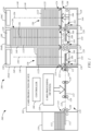
- FIG. 1 is a simplified illustration of a card production system 100 that includes a card production device 102 and one or more card stackers 104 formed in accordance with embodiments of the present disclosure. While the system 100 is shown as including a card stacker assembly 106 formed of three card stackers 104A-C, it is understood that embodiments of the present disclosure include systems 100 that include a single card stacker 104, or a card stacker assembly 106 comprising two or more card stackers 104.
- the system 100 also includes a controller 108 and one or more card processing devices 110.
- the controller 108 represents one or more distinct controllers of the system 100 each including at least one processor that is configured to execute program instructions stored in a computer-readable media or memory of the device 100, which may also be represented by the controller 108, or another location. Any suitable patent subject matter eligible computer readable media or memory may be utilized including, for example, hard disks, CD-ROMs, optical storage devices, flash memory, magnetic storage devices, or other suitable computer readable media or memory. Such computer readable media or memory do not include transitory waves or signals.
- the execution of the instructions by the controller 108 controls components of the system 100 to perform functions and method steps described herein.
- the one or more card processing devices 110 are each configured to perform a process on a card substrate 112.
- the card processing devices may include conventional card processing devices, such as a printing device configured to print an image to a surface of the card substrate 112 through a direct or transfer printing process, a laminating device configured to apply an overlaminate to a surface of the substrate 112, a data reading and/or writing device (e.g., a chip encoder, a magnetic stripe encoder, etc.) configured to read data from, and/or write data to, the substrate 112, a card flipper configured to invert the substrate 112, and/or another conventional card processing device.
- a printing device configured to print an image to a surface of the card substrate 112 through a direct or transfer printing process
- a laminating device configured to apply an overlaminate to a surface of the substrate 112
- a data reading and/or writing device e.g., a chip encoder, a magnetic stripe encoder, etc.
- a card flipper
- individual substrates 112 may be received at an input 114 by the card production device 110 from a card substrate supply 116, as shown in FIG. 1 , or another device of the system 100.
- a transport mechanism 118 feeds individual substrates 112 along a processing path 119 to the one or more processing devices 110.
- the transport mechanism 118 may include conventional motorized feed rollers and pinch roller pairs 120, as shown in FIG. 1 .
- the card stackers 104 may be positioned to receive individual card substrates 112 discharged through an output 122 of the card production device 102 by the transport mechanism 112, as shown in FIG. 1 .
- FIG. 2 is a simplified side view of an exemplary card stacker 104
- FIGS. 3 and 4 are isometric assembled and exploded views of an exemplary card stacker 104.
- each of the card stackers 104 includes a stack support 124, a card feed mechanism 126, and a card lift mechanism 128, as shown in FIG. 2 .
- the card feed mechanism 126 of each card stacker 104 is generally configured to feed individual card substrates 112 along a card feed path 130, which may be aligned with the processing path 119 ( FIG.
- Each lift mechanism 128 is configured to perform a lift operation on individual substrates 112 that are positioned in the lift position 132 within the card stacker 104.
- the lift operation which is illustrated as being performed by the card lift mechanism 128 of the card stacker 104C, delivers the substrate 112 from the lift position 132 in the card feed path 130 to the bottom of a card stack 136 of substrates 112S supported on the stack support 124.
- each card stacker 104 includes a stack housing 140 that is removably supported within a receptacle 142 of a base 144, which includes the card lift mechanism 128 and the card feed mechanism 126.
- the stack housing 140 defines an interior cavity 146 that is configured to contain the card stack 136, as shown in FIG. 2 .
- the housing 140 may include an access to the interior cavity 146, such as a hinged door 148 ( FIGS. 3 and 4 ) or other suitable access, for removal of the card stack 136.
- the door 148 may be locked using a suitable locking mechanism 150.
- the stack support 124 is supported at a bottom 152 of the stack housing 140 adjacent an opening 154 in the housing 140, and is configured to support the substrate stack 136 in a vertical column within the interior cavity 146 that is generally aligned with an axis 156.
- a substrate 112 is delivered through the opening 154 in the bottom 152 of the housing 140 adjacent the stack support 124 to the bottom of the substrate stack 136 and on the stack support 124.
- the stack support 124 may take on any suitable form.
- the stack support 124 includes multiple catch pawls 158 that may be pivoted in the direction indicated by arrows 160 ( FIG. 2 ) during a lift operation, but are restricted from pivoting in the direction opposite the arrows 160 past a support position, which is shown in FIG. 2 .
- the stack support 124 may include, for example, three or four catch pawls 158 that support the bottom surface 162 of the bottom substrate 112S of the stack 136 in a substantially perpendicular orientation to the axis 156, as shown in FIG. 2 .
- Each card feed mechanism 126 is configured to receive substrates 112 through a port 164, feed the individual substrates 112 along the card feed path 130 to the lift position 132, in which the substrate 112 is positioned for a lifting operation using the corresponding lift mechanism 128, or deliver the substrates to an adjoining card stacker 104 through a port 166 on the opposing side of the axis 156 from the port 164.
- a port 164 feeds the individual substrates 112 along the card feed path 130 to the lift position 132, in which the substrate 112 is positioned for a lifting operation using the corresponding lift mechanism 128, or deliver the substrates to an adjoining card stacker 104 through a port 166 on the opposing side of the axis 156 from the port 164.
- the card feed mechanism 126 of the card stacker 104A is configured to receive individual card substrates 112 discharged through the output 122 of the card production device 102 at the port 164 and feed the substrate 112 along the card feed path 130 to the lifting position 132, in which the lift mechanism 128 may perform a lift operation, or discharge the substrate 112 through the port 166 where it is received by the card feed mechanism 126 of the card stacker 104B through the port 164.
- the card feed mechanism 126 of the card stacker 104B may feed the substrate 112 received from the card stacker 104A to position it for a lift operation or handoff the substrate 112 to the card feed mechanism 126 of the card stacker 104C, such as indicated by the substrate 112 drawn in phantom lines.
- the card stacker 104C which is the last card stacker of the assembly 106 in the exemplary system 100 of FIG. 1 , may use its card feed mechanism 126 to position the card substrate 112 for a lift operation using its lift mechanism 128 to deliver the substrate 112 to the bottom of the card stack 136 supported by the stack support 124, as indicated in FIG. 1 , or discharge the card substrate 112 through the port 166, for example.
- the card feed mechanism 126 of each card stacker 104 has a suitable form.
- the card feed mechanism 126 includes pinch roller pairs 168, such as pinch roller pairs 168A and 168B, which are respectively positioned on opposing sides of the axis 156 adjacent the ports 164 and 166.
- Each of the pinch roller pairs 168 include upper and lower transport rollers 170 and 172, respectively, such as upper transport rollers 170A and 170B, and lower transport rollers 172A and 172B. While the card feed mechanism 126 is illustrated as having two pinch roller pairs 168A and 168B, embodiments of the present disclosure include the use of the single pinch roller pair or other configurations.
- the pinch roller pairs 168 are configured to drive a received substrate 112 along the card feed path 130 when in a feed position, such as shown in FIG. 2 .
- a feed position such as shown in FIG. 2 .
- one or both of the pinch roller pairs 168A and 168B pinch a received substrate 112 between the upper and lower transport rollers 170 and 172 and support the substrate 112 in substantial alignment with the card feed path 130.
- a motor 174 is configured to drive the pinch roller pairs 168, such as through a conventional mechanical linkage, to feed a received card substrate 112 along the card feed path 130.
- the motor 174 is configured to drive the lower transport rollers 172, and the upper transport rollers 170 are idler motors that are not directly driven by the motor 174.
- the card feed mechanism 126 includes a card sensor 176 that is configured to detect reception of a card substrate 112 fed along the card feed path 130, such as from the card production device 102 or an adjoining card stacker 104, for example.
- the card sensor 176 is used to detect a leading or trailing edge of the substrate 112 to establish a position of the substrate 112 relative to the card feed mechanism 126 along the card feed path 130. This allows the controller 108 to control the card feed mechanism 126 to position the substrate 112 in the lift position 132 along the card feed path 130, or handoff the substrate 112 to an adjoining card stacker 104.
- the motor 174 is a stepper motor, and the detection of the leading or trailing edge of the substrate 112 using the card sensor 176 allows the controller 108 to position the substrate 112 in a desired location along the card feed path 130 relative to the card feed mechanism 126 by driving the motor 174 a predetermined number of steps.
- the card feed mechanism 126 is configured to position a received substrate 112 in a lift position 132 ( FIG. 2 ) along the card feed path 130 for a lifting operation.
- the pinch roller pairs 168A and 168B simultaneously support the substrate 112 when it is in the lift position 132.
- the upper transport rollers 170 of the pinch roller pairs 168A and 168B each engage a top surface 178 of the card substrate 112 when it is in the lift position 132
- the bottom transport rollers 154 each engage a bottom surface 179 of the substrate 112 when it is in the lift position 132.
- the lift mechanism 126 include a card support member 180 and a drive mechanism 182, which is driven by a motor 183 ( FIG. 2 ), such as through a conventional mechanical linkage.
- the card support member 180 has a lowered position, shown in FIG. 2 , that corresponds to the feed position of the pinch roller pairs 168A and 168B and the lift or lowered position 132 of the card substrate 112, in which the substrate 112 is aligned with the card feed path 130, as shown in FIG. 2 .
- the card support member 180 includes a top surface 184 that can support the substrate 112 as it is fed along the card feed path 130.
- the leading edge of the substrate 112 may be supported by the top surface 184 of the card support member 180 as the leading edge of the card substrate 112 as it is fed to the pinch roller pair 168B.
- the lift mechanism 128 delivers a card substrate 112 supported on the card support member 180 from the lift position 132 ( FIG. 2 ) along the axis 156 through the opening 154 of the stack housing 140 to the bottom of the card stack 136 using the drive mechanism 182, as generally illustrated by the card stacker 104C in FIG. 1 .
- the drive mechanism 182 may take on any suitable form.
- the drive mechanism 182 includes a threaded rod 186 that is received within a threaded bore 188 of the card support member 180, as indicated in FIG. 2 .
- the rod 186 may be substantially coaxial to the axis 156.
- the motor 183 drives rotation of the rod 186 about the axis 156, and the threaded engagement with the card support member 180 drives the card support member 180 along the axis 156 either toward or away from the card stack 136.
- one or more components of the card feed mechanism 126 block the desired lifting path of the substrate 112 to the bottom of the card stack 136.
- the substrate 112 is supported between the pinch roller pairs 168A and 168B, and the upper transport rollers 170 engage the top surface 178 of the substrate 112.
- the position of the upper transport rollers 170 between the substrate 112 and the opening 154 to the housing 140 prevent the delivery of the substrate 112 to the bottom of the card stack 136.
- Each card stacker 104 includes a retraction mechanism, which is generally indicated by box 190 in FIG. 2 .
- the retraction mechanism 190 is configured to facilitate a lift or stacking operation by clearing the one or more components of the card feed mechanism 126 from the desired lifting path for substrate 112, which allows the lift mechanism 128 to deliver the substrate 112 to the bottom of the card stack 136 supported on the stack support 124.
- the retraction mechanism 190 is configured to move the upper transport rollers 170A and 170B of the pinch roller pairs 168A and 168B from the lifting path of the card substrate 112 to facilitate a lifting operation.
- FIGS. 2 and 5-9 are each simplified side views of an exemplary card stacker 104 during various stages of the lift or stacking operation.
- the substrate 112 is fed along the card feed path 130 to the lift position 132 shown in FIG. 2 .
- the card stack 136 is supported on a top side 192 of the stack support 124, and the substrate 112, the pinch roller pairs 168A and 168B and the top surface 184 of the card support member 180 are each positioned on a bottom side 194 of the stack support 124, as shown in FIG. 2 .
- the terms “top” and “bottom” refer to relative positions along the axis 156, in which the top side or position is located along the axis 156 in an upward direction, which is indicated by arrow 196, from the bottom side or position.
- the lift mechanism 128 raises the card support member 180 using the drive mechanism 182 in the upward direction 196.
- the retraction mechanism 190 moves the upper transport rollers 170 from their feed position, which is indicated in phantom lines, away from the axis 156 as indicated by arrows 198. This movement of the upper transport rollers 170 may also involve an upward movement of the upper transport rollers 170 from their feed positions along the axis 156. In some embodiments, this movement of the upper transport rollers 170 by the retraction mechanism 190 is driven in response to the upward movement of the card support member 180 by the lift mechanism 128. Thus, in some embodiments, the retraction mechanism 190 is driven by the drive mechanism 182 of the lift mechanism 128 using the motor 183.
- the upper transport rollers 170 reach a position in which they remain engaged with the card substrate 112, such as the top surface 178 or the side edges of the substrate 112, as shown in FIG. 5 .
- the upper transport rollers 170 continue to hold the substrate 112 in the lift position 132 relative to the axis 156 following this initial raising of the substrate 112 toward the card stack 136.
- the upper transport rollers 170 continue to be moved further from the axis 156 from their position in FIG. 5 (shown in phantom lines) by the retraction mechanism 190 until they are outside a projection of the substrate 112 along the axis 156, as shown in FIG. 6 . Further movement of the upper transport rollers from their position in FIG. 6 (shown in phantom lines) allows the lift mechanism 128 to continue to deliver the substrate 112 along the axis 156 toward the opening 154 in the stack housing 140 to the stack support 124 (e.g., catch pawls 158), as shown in FIG. 7 .
- the stack support 124 e.g., catch pawls 158
- the retraction mechanism 190 moves the upper transport rollers 170 from their feed position ( FIG. 2 ), in which the upper transport rollers 170 engage the top surface 178 of the substrate 112, to a retracted position ( FIG. 6 ), in which the upper transport rollers 170 are displaced from the lifting path of the substrate 112 and are positioned below the substrate 112, in response to the raising of the substrate 112 by the lift mechanism 128.
- the card support member 180 is driven by the drive mechanism 182 to raise the substrate 112 along the axis 156 to the top side 192 of the stack support 124 and in engagement with the bottom of the stack 136, as shown in FIG. 8 .
- the drive mechanism 182 delivers the substrate 112 through the catch pawls 158, which rotate in the direction 160 ( FIG. 2 ), and in engagement with the bottom substrate 112S of the stack 136. This positions the substrate 112 on the top side 192 of the stack support 124.
- the card support member 180 is then lowered along the axis 156 by the drive mechanism 182 to the lowered position, as shown in FIG. 9 .
- the catch pawls 158 rotate in the direction opposite the arrows 160 ( FIG. 2 ) to their support position, in which they support the substrate 112 and the rest of the card stack 136.
- the retraction mechanism 190 pivots the upper transport rollers 170A and 170B of the pinch roller pairs 168A and 168B from their retracted position (shown in phantom lines) to their feed position, as indicated by the arrows in FIG. 9 , to complete the card stacking operation.
- the card feed mechanism 126 and the lift mechanism 128 are positioned to receive a new substrate 112' fed along the card feed path 130, as indicated in FIG. 9 .
- the retraction mechanism 190 can take on any suitable form while driving movement of the upper transport rollers 170 from their feed position ( FIG. 2 ) to their retracted position (e.g., FIG. 8 ). Exemplary embodiments of the retraction mechanism 190 will be described with reference to FIGS. 10-14 .
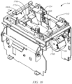
- FIG. 10 is an isometric view of an exemplary base 144 of a card stacker 104, in accordance with embodiments of the present disclosure.
- FIGS. 11-14 are side cross-sectional views of the base 144 of FIG. 10 taken generally along line 11-11, during various stages of a substrate lifting or stacking operation.
- the upper transport roller 170A and the bottom transport roller 172A are shown in phantom lines in order to show features of the retraction mechanism 190.
- the retraction mechanism 190 includes pivotable supports 200A and 200B, which are respectively attached to the card support member 180 through suitable pivotable connections 202A and 202B, such as hinges, for example.
- the pivotable connections 202A and 202B allow the supports 200A and 200B to respectively pivot about axes 204A and 204B, which are generally perpendicular to the direction the substrates 112 are fed along the card feed path and the axis 156.
- the upper transport roller 170A is connected to the support 200A and the upper roller 170B is connected to the support 200B.
- the transport rollers 170A and 170B move with movement of the corresponding support 200A and 200B.
- the transport rollers 170A and 170B have a fixed position relative to the corresponding support 200A and 200B.
- the support 200A may be biased to pivot about the axis 204A in the direction indicated by arrow 206A, and the support 200B may be biased to pivot about the axis 204B in the direction indicated by arrow 206B.
- this biasing of the supports 200A and 200B is facilitated using conventional techniques, such as a coil spring or another suitable biasing mechanism.
- the biasing of the supports 200A and 200B about the corresponding axes 204A and 204B also biases the upper transport rollers 170A and 170B in the same manner. As a result, when the pinch rollers 168A and 168B are in their feed position ( FIGS.
- the upper transport rollers 170A and 170B are generally biased toward the top surface 178 of the card substrate 112 and pinch the card substrate 112 against the corresponding lower transport rollers 172A and 172B, which engage the bottom surface 179 of the card substrate 112.
- the pinch roller pair 168A is configured to pinch the card substrate 112 in the lift position 132 adjacent a first edge 207 of the card substrate 112
- the pinch roller pair 168B is configured to pinch the substrate 112 in the lift position 132 adjacent a second edge 208 of the substrate 112 that is opposite the first edge 207, as best shown in FIG. 2 .
- the movement of the transport rollers 170A and 170B from the feed position to the retracted position is driven in response to movement of the card support member 180 from the lowered position ( FIG. 2 ) to the raised position ( FIG. 8 ) during a substrate lifting or stacking operation.
- the movement of the card support member 180 from the lowered position to the raised position drives each of the supports 200A and 200B to respectively pivot about the axes 204A and 204B, and transitions the transport rollers 170A and 170B from the feed position ( FIG. 2 ) to the retracted position ( FIG. 8 ). This can be accomplished using any suitable technique.
- the transport rollers 170A and 170B are driven from the feed position to the retracted position through engagement between the supports 200A and 200B and the bottom transport rollers 172A and 172B.
- the supports 200A and 200B may respectively include a slot 210A and 210B through which shafts 212 of the corresponding bottom rollers 172A extend.
- the shafts 212 are supported by a frame 200 of the base 144 and have a fixed position relative to the frame 200. As a result, the card support member 180, the supports 200A and 200B, and the transport rollers 170A and 170B move relative to the shafts 212 during movement of the card support member 180 along the axis 156.
- the shafts 212 slide within the slots 210A and 210B relative to the supports 200A and 200B.
- the slots 210A and 210B are shaped to pivot the supports 200A and 200B and drive the transport rollers 170A and 170B from the feed position to the retracted position along a desired path in response to the relative movement between the shafts 212 and the supports 200A and 200B.
- a card substrate 112 may be fed along the card feed path 130 to the lift position 132, as shown in FIGS. 2 and 11 .
- the upper transport rollers 170A and 170B are biased toward the top surface 178 of the substrate 112 and pinch the substrate 112 against the bottom rollers 172A and 172B.
- the card support member 180 engages the bottom surface 179 of the substrate 112 as the card support member 180 is raised from its lowered position along the axis 156, as shown in FIGS. 5 and 12 .
- the upper transport rollers 170A and 170B are displaced from the corresponding bottom rollers 172A and 172B and may be rotated slightly about the corresponding axes 204A and 204B away from the central axis 156 in response to the engagement between the shafts 212 and the corresponding slots 210A and 210B, as shown in FIGS. 6 and 12 .
- FIG. 13 illustrates the card support member 180 driving the substrate 112 through the opening 154 in the bottom of the stack housing 140
- FIG. 14 illustrates the card support member 180 positioning the substrate 112 in the fully raised position, in which the substrate 112 is positioned on the top side 192 of the stack support 124, which is also shown in FIG.
- the retracted positions (e.g., FIGS. 8 and 14 ) of the upper transport rollers 170A and 170B position the rollers 170A and 170B on the bottom side 194 of the stack support 124 and outside of the lifting path of the substrate corresponding to a projection of the substrate 112 along the axis 156.
- the card support member 180 is then lowered along the axis 156 through the opening 154 in the housing 140 and back to its lowered position shown in FIGS. 2 and 11 using the lift mechanism 128. This movement of the card support member 180 pivots the supports 200A and 200B about the axes 204A and 204B and drives the upper transport rollers from the retracted position ( FIGS. 8 and 14 ) to the feed position ( FIGS. 2 and 11 ), to prepare the base 144 for receiving another card substrate 112.
- the card stacker 104 includes a card stack sensor 220 ( FIGS. 1 and 2 ) that is configured to detect when the stack housing reaches a full condition, such as illustrated by card stacker 104B in FIG. 1 , in which it no longer accepts additional substrates in the card stack 136.
- the card stack sensor 220 is configured to detect a position of the top substrate 112T in the stack 136 that indicates the full condition. This may be accomplished using any suitable sensor arrangement.
- the card stack sensor 220 includes a passive or mechanical sensing element 222 in the stack housing 140 and an active or electronic sensor 224 in the base 144, as shown in FIGS. 15 and 16 , which are simplified partial side views of a card stacker 104 in accordance with embodiments of the present disclosure. This allows the card stacker 104 to provide the desired full stack sensing feature without electrical connections between the stack housing 140 and the base 144.
- the passive sensing element 222 includes a mechanical switch 226 positioned at the top end 228 of the interior cavity 146 of the stack housing 140.
- the active sensor 224 may be any suitable active sensor, such as an optical or capacitive sensor, that is supported in the base 144 adjacent the receptacle 142 that receives the bottom 152 of the housing 140.
- the top substrate 112T in the stack 136 does not trigger the mechanical switch 226, as shown in FIG. 15 .
- the top substrate 112T rises relative to the mechanical switch 226 and transitions the switch 226 from the first (not full) position ( FIG. 15 ), to a second position indicating a full condition, as shown in FIG. 16 .
- the mechanical switch 226 may take on any suitable form.
- the mechanical switch 226 may comprise a lever arm 230 that is configured to pivot about an axis 232 from the first position to the second position in response to the rising stack of substrates 126.
- a rod 234 is attached to an end 236 of the lever arm 230 and generally moves along the axis 156 in response to movement of the lever arm 230 from the first position to the second position.
- An end 238 of the rod 234 may initially be positioned for detection by the active sensor 224 when the lever arm 230 is in the first position, as shown in FIG. 15 .
- the end 238 of the rod 234 is lowered and moved out of the detection zone of the active sensor 224.
- This lack of detection of the end 238 of the rod 234 by the active sensor 224 may be used by the controller 108 to detect the full condition of the substrate stack 136.
- the mechanical switch 226 may be arranged to position the end 238 outside the detection zone of the active sensor 224 when the card stack 136 has not reached the full condition, and position the end 238 within the detection zone of the active sensor 224 when the card stack 136 has reached the full condition.
- Other card stack sensing arrangements may also be used to provide the desired detection of the full card stack condition within the stack housing 140.
- the active sensor 224 may also be used to detect whether the stack housing 140 is properly installed on the base 144. For instance, when the stack housing 140 is properly installed on the base 144 and the card stack 136 is not full, the lever arm 230 is in the first position and the end 238 of the rod 234 is positioned within the detection zone of the active sensor 224, as shown in FIG. 15 . However, if the housing 140 is not properly seated within the receptacle 142 of the base 144, the active sensor 224 will not detect the end 238 of the rod 234. Thus, the controller 108 can use the detection of the end 238 of the rod 234 by the active sensor 224 to determine that the stack housing 140 is properly installed within the receptacle 142 of the base 144.
- the controller 108 may enable substrate lifting or stacking operations to be performed by the card stacker 104, when the active sensor 224 detects the end 238 of the rod 234, and disable substrate lifting or stacking operations when the active sensor 224 does not detect the end 238 of the rod 234, as this may indicate that the stack housing 140 is either not installed on the base 144, is improperly installed on the base 144, or the card stack 136 has reached a full condition. However, the controller 108 may still use the base 144 to receive and pass substrates 112 to an adjoining card stacker 104 when card lifting or stacking operations are disabled. This is generally illustrated in FIG. 1 , in which card stacker 104B has reached a full condition, but is able to pass a substrate 112 (shown in phantom lines) to the card stacker 104C.
- embodiments of the present disclosure include a card stacker 104 that is configured to deliver a card substrate 112 to a bottom of a stack 136 of card substrates 112S.
- the card stacker 104 includes a stack support 124, a card feed mechanism 126, a card lift mechanism 128, and a retraction mechanism 190, as shown in FIG. 2 .
- the stack support 124 is configured to hold the stack 136 of card substrates 112 on a top side 192 of the stack support 124 that is opposite a bottom side 194 of the stack support 124.
- the card lift mechanism 128 is configured to support the card substrate 112 in a lowered position ( FIG.
- FIG. 8 a raised position in which the card substrate 112 is positioned at the bottom of the stack of card substrates 126 and is supported on the top side 192 of the stack support 124.
- Embodiments of the card feed mechanism 126 include an upper transport roller 170A having a feed position ( FIG. 2 ) when the card substrate 112 is in the lowered position, and a retracted position ( FIG. 8 ) when the card substrate 112 is in the raised position.
- the upper transport roller 170A engages a top surface 178 of the card substrate 112 that faces the bottom side 194 of the stack support 124 when in the feed position ( FIG. 2 ).
- the upper transport roller 170A is positioned on the bottom side 194 of the stack support 124 when in the retracted position ( FIG. 8 ).
- the retraction mechanism 190 is configured to move the upper transport roller 170A between the feed and retracted positions, as discussed above with reference to FIGS. 4-9 and 11-14 .
- the card lift mechanism 128 includes a card support member 180 and a drive mechanism 182.
- the drive mechanism 182 is driven by a motor 183 and drives the card support member 180 between a lowered position ( FIGS. 2 and 11 ) corresponding to the lowered position of the card substrate 112, and a raised position ( FIGS. 8 and 14 ) corresponding to the raised position of the card substrate 112.
- the retraction mechanism 190 includes a first pivotable support 200A that is attached to the card support member 180 and is configured to pivot the upper transport roller 170A about a support axis 204A to the retracted position in response to movement of the card support member 180 from the lowered position to the raised position, as discussed above with reference to FIGS. 11-14 .
- the card feed mechanism 126 includes a lower transport roller 172A, and the card substrate 112 is pinched between the transport rollers 170A and 172A when the card substrate 112 is in the lowered position, such as shown in FIGS. 2 and 11 .
- the pivotable support 200A of the retraction mechanism 190 is biased to pivot the upper transport roller 170A about the first support axis 204A toward the top surface 178 of the card substrate 112 when the card substrate 112.
- the transport rollers 170A and 172A form a first pinch roller pair 168A that is configured to pinch the card substrate 112 in the lowered position adjacent a first edge 207 of the card substrate 112.
- the card feed mechanism 126 includes a second pinch roller pair 168B that includes upper and lower transport rollers 170B and 172B, which pinch the card substrate 112 in the lowered position at a second edge 208 of the card substrate 112 that is opposite the first edge 207, as shown in FIG. 2 .
- the upper transport roller 170B includes a feed position when the card substrate 112 is in the lowered position, as shown in FIGS. 2 and 11 , and a retracted position when the card substrate is in the raised position, as shown in FIGS. 8 and 14 .
- the upper transport roller 170B engages the top surface 178 of the card substrate 112 when in the feed position, and the upper transport roller 170B is on the bottom side of the stack support 124 when in the retracted position, as shown in FIGS. 2 and 8 .
- the retraction mechanism 190 is configured to move the upper transport roller 170B between the feed and retracted positions, as discussed above with reference to FIGS. 2-9 and 11-14 .
- the retraction mechanism 190 includes a second pivotable support 200B that is attached to the card support member 180 and is configured to pivot the upper transport roller 170B about a second support axis 204B to the retracted position in response to movement of the card support member 180 from the lowered position to the raised position.
- Additional embodiments are directed to a method of performing a substrate stacking operation using the card stacker 104 formed in accordance with one or more embodiments described herein.
- a card substrate 112 is received using a card feed mechanism 126 of the card stacker 104 that includes a transport roller 170, such as shown in FIGS. 1 and 2 .
- the card substrate 112 is supported in a lift position ( FIG. 2 ) in a card path 130 on a bottom side 194 of the stack support 124.
- a top surface 178 of the card substrate 112 that faces the bottom side 194 of the stack support 124 is engaged with the upper transport roller 170 (e.g., roller 170A), in a feed position, as shown in FIG. 2 .
- the upper transport roller 170 e.g., roller 170A
- the card substrate 112 is then raised from the lift position to a raised position, in which the card substrate 112 is positioned on the bottom of the stack of card substrates 136 and supported on the top side 192 of the stack support 124 using a card lift mechanism 124, as discussed above with reference to FIGS. 2-8 and 11-14 .
- the transport roller 170 is moved from the feed position to a retracted position, in which the transport roller is positioned on the bottom side 194 of the stack support 124.
Landscapes
- Engineering & Computer Science (AREA)
- Mechanical Engineering (AREA)
- Pile Receivers (AREA)
- Conveying Record Carriers (AREA)
Claims (13)
- Kartenstapler (104) zur Verwendung mit einer Kartenproduktionsvorrichtung (102), der dafür ausgelegt ist, einem Bodenbereich eines Stapels (136) aus Kartensubstraten (112) ein Kartensubstrat (112) zuzuführen, wobei der Kartenstapler (104) aufweist:eine Stapelauflage (124), die dafür ausgelegt ist, den Stapel (136) aus Kartensubstraten (112) an einer Oberseite (192) der Stapelauflage (124) zu halten, die sich entgegengesetzt zu einer Unterseite (194) der Stapelauflage (124) befindet;einen Kartenhebemechanismus (128), der dafür ausgelegt ist, das Kartensubstrat (112) in einer Hubposition (132) an der Unterseite (194) der Stapelauflage (124) abzustützen und das Kartensubstrat (112) in eine erhöhte Position zu fahren, in der das Kartensubstrat (112) am Bodenbereich des Stapels (136) aus Kartensubstraten (112) positioniert ist und durch die Oberseite (192) der Stapelauflage (124) abgestützt ist;einen Kartenzuführmechanismus (126), der eine erste Transportwalze (170A) aufweist, die eine Zuführposition, wenn sich das Kartensubstrat (112) in der Hubposition (130) befindet, und eine zurückgezogene Position hat, wenn sich das Kartensubstrat (112) in der erhöhten Position befindet, wobei:die erste Transportwalze (170A), wenn sie sich in der Zuführposition befindet, an einer oberen Oberfläche des Kartensubstrats (112) angreift, die der Unterseite (194) der Stapelauflage (124) zugewandt ist; undwenn sie sich in der zurückgezogenen Position befindet, ist die erste Transportwalze (170A) von einem Hubweg des Kartensubstrats (112) versetzt, der zwischen der Hubposition und erhöhten Position definiert ist; undeinen Rückziehmechanismus (190), der dafür ausgelegt ist, die erste Transportwalze (170A) zwischen der Zuführposition und der zurückgezogenen Position zu bewegen.
- Kartenstapler (104) nach Anspruch 1, wobei der Kartenhebemechanismus (128) umfasst:ein Kartenabstützelement (180); undeinen Antriebsmechanismus (182), der dafür ausgelegt ist, das Kartenabstützelement (180) zwischen einer abgesenkten Position, die der Hubposition (132) des Kartensubstrats (112) entspricht, und einer erhöhten Position anzutreiben, die der erhöhten Position des Kartensubstrats (112) entspricht.
- Kartenstapler (104) nach Anspruch 2, wobei der Rückziehmechanismus (190) eine erste schwenkbare Abstützung (200A) umfasst, die am Kartenabstützelement (180) angebracht und dafür ausgelegt ist, die erste Transportwalze (170A) um eine erste Abstützachse zur zurückgezogenen Position zu verschwenken, und zwar im Ansprechen auf eine Bewegung des Kartenabstützelements (180) von der abgesenkten Position zur erhöhten Position.
- Kartenstapler (104) nach Anspruch 2 oder 3, wobei der Kartenzuführmechanismus (126) eine zweite Transportwalze (170B) umfasst und das Kartensubstrat (112) zwischen der ersten (170A) und zweiten Transportwalze (170B) eingeklemmt ist, wenn sich das Kartensubstrat (112) in der Hubposition befindet.
- Kartenstapler (104) nach Anspruch 3 oder 4, wobei die schwenkbare Abstützung vorgespannt ist, um die erste Transportwalze (170A) um die erste Abstützachse zur oberen Oberfläche des Kartensubstrats (112) zu verschwenken, wenn sich das Kartensubstrat (112) in der Hubposition befindet.
- Kartenstapler (104) nach Anspruch 4 oder 5, wobei:die erste (170A) und zweite Transportwalze (170B) ein erstes Klemmwalzenpaar (168A) bilden, das dafür ausgelegt ist, das Kartensubstrat in der Hubposition (132) angrenzend an einen ersten Rand (207) des Kartensubstrats (112) einzuklemmen; undder Kartenzuführmechanismus (126) ein zweites Klemmwalzenpaar (168B) umfasst, das eine dritte (170B) und eine vierte Transportwalze (172B) aufweist, wobei das Kartensubstrat (112) in der Hubposition (132) zwischen der dritten (170B) und vierten Transportwalze (172B) an einem zweiten Rand (208) des Kartensubstrats (112) eingeklemmt ist, der entgegengesetzt zum ersten Rand (207) ist.
- Kartenstapler (104) nach Anspruch 6, wobei:die dritte Transportwalze (170B) eine Zuführposition umfasst, wenn sich das Kartensubstrat (112) in der Hubposition (132) befindet, und eine zurückgezogene Position umfasst, wenn sich das Kartensubstrat (112) in der erhöhten Position befindet;die dritte Transportwalze (170B) an der oberen Oberfläche des Kartensubstrats (112) angreift, wenn sie sich in der Zuführposition befindet;die dritte Transportwalze (170B) vom Hubweg des Kartensubstrats (112) versetzt ist, wenn sie sich in der zurückgezogenen Position befindet; undder Rückziehmechanismus (190) dafür ausgelegt ist, die dritte Transportwalze (170B) zwischen der Zuführposition und der zurückgezogenen Position zu bewegen.
- Kartenstapler (104) nach Anspruch 6 oder 7, wobei der Rückziehmechanismus (190) eine zweite schwenkbare Abstützung (200B) umfasst, die am Kartenabstützelement (180) angebracht und dafür ausgelegt ist, die dritte Transportwalze (170B) um eine zweite Abstützachse zur zurückgezogenen Position zu verschwenken, und zwar im Ansprechen auf eine Bewegung des Kartenabstützelements (180) von der abgesenkten Position zur erhöhten Position.
- Kartenstapler (104) nach einem der Ansprüche 2 bis 8, wobei das Kartenabstützelement (180) an einer unteren Oberfläche des Kartensubstrats (112) angreift, die entgegengesetzt zur oberen Oberfläche ist, und das Kartensubstrat (112) während der Bewegung des Kartenabstützelements (180) von der abgesenkten Position zur erhöhten Position von der Unterseite der Stapelauflage (124) zur Oberseite (192) der Stapelauflage (124) fährt.
- Kartenstapler (104) nach Anspruch 9,wobei die Stapelauflage (124) eine Vielzahl von Greifklinken (158) aufweist;
UND/ODERwobei:der Antriebsmechanismus (182) einen Motor und eine Gewindestange umfasst, die in einer Gewindebohrung des Kartenabstützelements (180) aufgenommen ist; unddas Kartenabstützelement (180) im Ansprechen auf eine Drehung der durch den Motor angetriebenen Gewindestange von der abgesenkten Position zur erhöhten Position gefahren wird;
UND/ODERwobei:der Kartenzuführmechanismus (126) dafür ausgelegt ist, Kartensubstrate (112) entlang einer Kartenzuführbahn (130) zuzuführen; undder Kartenstapler (104) einen Kartensensor (176) umfasst, der dafür ausgelegt ist, das Vorhandensein oder Nichtvorhandensein eines Kartensubstrats (112) in der Kartenzuführbahn (130) zu erfassen,
UND/ODERdarüber hinaus aufweisend:ein Stapelgehäuse (140) mit einem Bodenbereichsende, das die Stapelauflage (220) abstützt; undeinen Stapelsensor (176), der dafür ausgelegt ist, ein oberes Kartensubstrat (112) in dem Stapel (136) aus Kartensubstraten (112) abzufühlen, das entgegengesetzt zum Bodenbereich des Stapels (136) aus Kartensubstraten (112) ist. - Kartenstapler (104) nach Anspruch 2, darüber hinaus eine erste Öffnung aufweisend, durch die der Kartenzuführmechanismus (126) dafür ausgelegt ist, einzelne Kartensubstrate (112) zu empfangen oder auszugeben, wenn sich das Kartenabstützelement (180) in der abgesenkten Position befindet, und optional eine zweite Öffnung aufweisend, durch die der Kartenzuführmechanismus (126) dafür ausgelegt ist, einzelne Kartensubstrate (112) zu empfangen oder auszugeben, wenn sich das Kartenabstützelement (180) in der abgesenkten Position befindet, wobei sich die zweite Öffnung auf einer zur ersten Öffnung entgegengesetzten Seite des Kartenhebemechanismus (128) befindet.
- Kartenstapleranordnung (106), der eine Vielzahl von Kartenstaplern (104) umfasst, wobei jeder aus der Vielzahl von Kartenstaplern (104) eine Kartenstapler (104) nach Anspruch 7 ist, wobeifür jeden Kartenstapler (104) das erste (168A) und zweite Klemmwalzenpaar (168B) jeweils dafür ausgelegt ist, einzelne Kartensubstrate (112) entlang einer Kartenbahn (130) durch eine erste und eine zweite Öffnung, die an entgegengesetzten Seiten des Kartenhebemechanismus (128) positioniert sind, zu empfangen oder auszugeben;die Vielzahl von Kartenstaplern (104) in einer nebeneinanderliegenden Anordnung positioniert sind; undeine Kartensubstrat (112), das durch die zweite Öffnung von einem der Kartenstapler (104) ausgegeben wird, durch die erste Öffnung eines benachbarten Kartenstaplers (104) empfangen wird.
- Verfahren zum Hinzufügen eines Kartensubstrats (112) zu einem Bodenbereich eines Stapels (136) aus Kartensubstraten (112), die an einer Oberseite (192) einer Stapelauflage (124) eines Kartenstaplers (104) abgestützt sind, wobei das Verfahren umfasst:Empfangen des Kartensubstrats (112) mit einem Kartenzuführmechanismus (126) des Kartenstaplers (104), wobei der Kartenzuführmechanismus (126) eine Transportwalze umfasst;Abstützen des Kartensubstrats (112) in einer abgesenkten Position an einer Unterseite (194) der Stapelauflage (124), wobei dieser Vorgang umfasst, an einer oberen Oberfläche des Kartensubstrats (112), die der Unterseite (194) der Stapelauflage (124) zugewandt ist, mit der Transportwalze in einer Zuführposition anzugreifen;Anheben des Kartensubstrats (112) von der abgesenkten Position zu einer erhöhten Position, in der das Kartensubstrat (112) am Bodenbereich des Stapels (136) aus Kartensubstraten (112) positioniert und an der Oberseite (192) der Stapelauflage (124) abgestützt ist, unter Verwendung eines Kartenhebemechanismus (128) des Kartenstaplers (104); undwährend des Anhebens des Kartensubstrate, Bewegen der Transportwalze von der Zuführposition zu einer zurückgezogenen Position, in der die Transportwalze von einem Hubweg des Kartensubstrats (112), der zwischen der abgesenkten und der erhöhten Position definiert ist, versetzt ist;und optional aufweisend, eine Bearbeitung an dem Kartensubstrat (112) unter Verwendung einer Kartenbearbeitungsvorrichtung durchzuführen, bevor das Kartensubstrat (112) mit dem Kartenzuführmechanismus empfangen wird, wobei die Bearbeitung aus der Gruppe ausgewählt ist, die aus Folgendem besteht:Drucken eines Bildes auf das Kartensubstrat (112);Laminieren eines Überlaminats auf das Kartensubstrat (112); undCodieren von Daten auf dem Kartensubstrat (112).
Applications Claiming Priority (1)
| Application Number | Priority Date | Filing Date | Title |
|---|---|---|---|
| US16/265,267 US10807823B2 (en) | 2019-02-01 | 2019-02-01 | Card stacker |
Publications (2)
| Publication Number | Publication Date |
|---|---|
| EP3699129A1 EP3699129A1 (de) | 2020-08-26 |
| EP3699129B1 true EP3699129B1 (de) | 2025-01-22 |
Family
ID=69400385
Family Applications (1)
| Application Number | Title | Priority Date | Filing Date |
|---|---|---|---|
| EP20154281.8A Active EP3699129B1 (de) | 2019-02-01 | 2020-01-29 | Kartenstapler |
Country Status (3)
| Country | Link |
|---|---|
| US (1) | US10807823B2 (de) |
| EP (1) | EP3699129B1 (de) |
| CN (1) | CN111517143B (de) |
Families Citing this family (4)
| Publication number | Priority date | Publication date | Assignee | Title |
|---|---|---|---|---|
| US11667489B2 (en) * | 2020-11-25 | 2023-06-06 | Ncr Corporation | Short travel pusher plate stacking bin |
| CN112849911B (zh) * | 2021-03-01 | 2025-03-11 | 范德兰德物流自动化系统(上海)有限公司 | 拆框装置、安检系统、拆框方法及计算机可读存储介质 |
| JP7570701B2 (ja) * | 2022-01-14 | 2024-10-22 | 旭精工株式会社 | カード処理装置 |
| US20240217765A1 (en) * | 2023-01-04 | 2024-07-04 | Melissa Ketcherside | Card making alignment device |
Family Cites Families (16)
| Publication number | Priority date | Publication date | Assignee | Title |
|---|---|---|---|---|
| US2595346A (en) * | 1948-09-04 | 1952-05-06 | Scriptomatic Inc | Stacking device for cards or the like |
| US3870166A (en) * | 1970-09-21 | 1975-03-11 | Hoerner Waldorf Corp | Stacking and transferring unit |
| GB1396138A (en) | 1972-11-03 | 1975-06-04 | Spicers Stationery Ltd | Apparatus for delivering and stacking folded sheet material |
| CH648262A5 (de) * | 1980-08-15 | 1985-03-15 | Ferag Ag | Vorrichtung zum bilden von stapeln aus kontinuierlich, insbesondere in einem schuppenstrom, anfallenden flaechigen erzeugnissen, vorzugsweise druckprodukten. |
| US4560293A (en) | 1983-10-14 | 1985-12-24 | Check Technology Corporation | Document printing method and apparatus |
| JPH06104526B2 (ja) | 1985-02-28 | 1994-12-21 | ジューキ株式会社 | カ−ド区分け機構 |
| JPS63171760A (ja) | 1987-01-08 | 1988-07-15 | Omron Tateisi Electronics Co | カ−ド回収装置 |
| US5415519A (en) * | 1993-05-20 | 1995-05-16 | Rimage Corporation | Upstacker and orientation collator |
| US5837991A (en) | 1996-03-08 | 1998-11-17 | Card Technology Corporation | Card transport mechanism and method of operation |
| US6199857B1 (en) * | 1999-09-22 | 2001-03-13 | Fargo Electronics, Inc. | I. D. card output stacker |
| US6431537B1 (en) | 2000-06-27 | 2002-08-13 | Fargo Electronics, Inc. | Multiple card hopper for card printer |
| DE10342512B3 (de) * | 2003-09-12 | 2004-10-28 | Atotech Deutschland Gmbh | Vorrichtung und Verfahren zum elektrolytischen Behandeln von elektrisch gegeneinander isolierten, elektrisch leitfähigen Strukturen auf Oberflächen von bandförmigem Behandlungsgut |
| ES2565477T3 (es) * | 2009-09-18 | 2016-04-05 | Assa Abloy Ab | Conjunto de tolva doble |
| CN102963753B (zh) * | 2012-11-02 | 2016-03-30 | 无锡明珠增压器制造有限公司 | 电路基板堆叠机 |
| KR102356400B1 (ko) | 2016-06-09 | 2022-01-26 | 인트러스트 코포레이션 | 카드 기구 어레이 |
| CN207632209U (zh) * | 2017-11-13 | 2018-07-20 | 天津市旭辉恒远塑料包装股份有限公司 | 一种塑料编织袋垛堆码机构 |
-
2019
- 2019-02-01 US US16/265,267 patent/US10807823B2/en active Active
-
2020
- 2020-01-29 EP EP20154281.8A patent/EP3699129B1/de active Active
- 2020-02-03 CN CN202010079194.4A patent/CN111517143B/zh active Active
Also Published As
| Publication number | Publication date |
|---|---|
| CN111517143A (zh) | 2020-08-11 |
| US20200247637A1 (en) | 2020-08-06 |
| US10807823B2 (en) | 2020-10-20 |
| EP3699129A1 (de) | 2020-08-26 |
| CN111517143B (zh) | 2022-02-15 |
Similar Documents
| Publication | Publication Date | Title |
|---|---|---|
| EP3699129A1 (de) | Kartenstapler | |
| US8646770B2 (en) | Card substrate rotator with lift mechanism | |
| EP3383662B1 (de) | Kartendruckmechanismus kartenrückweg | |
| EP2477918B1 (de) | Doppelmagazinanordnung | |
| CN111517133B (zh) | 卡片翻转器、卡片翻转器模块及卡片生产装置 | |
| EP2214992B1 (de) | Vorrichtung zur herstellung von berechtigungsnachweisen mit einem zusätzlichen karteneingang | |
| EP3689621B1 (de) | Tintenstrahlkartendrucker und verfahren mit doppelbandkartentransport | |
| JP2007041635A (ja) | カード処理装置 | |
| US8876110B2 (en) | Credential manufacturing device substrate shuttle | |
| US9679229B2 (en) | Credential production device card substrate rotator | |
| JP5770076B2 (ja) | 冊子状媒体処理装置 | |
| KR101459387B1 (ko) | 메일링 시스템의 연속식 안내장 투입장치 | |
| CN102867358A (zh) | 介质处理装置 | |
| JP4708814B2 (ja) | 通帳発行モジュール | |
| CN116788814B (zh) | 传送装置及物体传送方法 | |
| KR101326545B1 (ko) | 통장 발행 장치의 제어 방법 | |
| JP2011201281A (ja) | 冊子の折り畳み装置、及び冊子発行装置 | |
| KR20210144988A (ko) | 매체 입금기 | |
| CN116788814A (zh) | 传送装置及物体传送方法 | |
| JP4578962B2 (ja) | カード処理装置 | |
| JP5075936B2 (ja) | 冊子発行装置 | |
| CN112573275A (zh) | 排纸装置、排纸装置的控制方法、处理装置以及记录系统 | |
| JP2001236549A (ja) | 媒体発行装置 | |
| KR20160045987A (ko) | 매체 저장부 | |
| WO2013084540A1 (ja) | 通帳類取扱装置 |
Legal Events
| Date | Code | Title | Description |
|---|---|---|---|
| PUAI | Public reference made under article 153(3) epc to a published international application that has entered the european phase |
Free format text: ORIGINAL CODE: 0009012 |
|
| STAA | Information on the status of an ep patent application or granted ep patent |
Free format text: STATUS: THE APPLICATION HAS BEEN PUBLISHED |
|
| AK | Designated contracting states |
Kind code of ref document: A1 Designated state(s): AL AT BE BG CH CY CZ DE DK EE ES FI FR GB GR HR HU IE IS IT LI LT LU LV MC MK MT NL NO PL PT RO RS SE SI SK SM TR |
|
| AX | Request for extension of the european patent |
Extension state: BA ME |
|
| RAP1 | Party data changed (applicant data changed or rights of an application transferred) |
Owner name: ASSA ABLOY AB |
|
| STAA | Information on the status of an ep patent application or granted ep patent |
Free format text: STATUS: REQUEST FOR EXAMINATION WAS MADE |
|
| 17P | Request for examination filed |
Effective date: 20201124 |
|
| RBV | Designated contracting states (corrected) |
Designated state(s): AL AT BE BG CH CY CZ DE DK EE ES FI FR GB GR HR HU IE IS IT LI LT LU LV MC MK MT NL NO PL PT RO RS SE SI SK SM TR |
|
| STAA | Information on the status of an ep patent application or granted ep patent |
Free format text: STATUS: EXAMINATION IS IN PROGRESS |
|
| 17Q | First examination report despatched |
Effective date: 20221220 |
|
| P01 | Opt-out of the competence of the unified patent court (upc) registered |
Effective date: 20230627 |
|
| REG | Reference to a national code |
Ref country code: DE Ref legal event code: R079 Free format text: PREVIOUS MAIN CLASS: B65H0029120000 Ref country code: DE Ref legal event code: R079 Ref document number: 602020045034 Country of ref document: DE Free format text: PREVIOUS MAIN CLASS: B65H0029120000 Ipc: B65H0031240000 |
|
| GRAP | Despatch of communication of intention to grant a patent |
Free format text: ORIGINAL CODE: EPIDOSNIGR1 |
|
| STAA | Information on the status of an ep patent application or granted ep patent |
Free format text: STATUS: GRANT OF PATENT IS INTENDED |
|
| RIC1 | Information provided on ipc code assigned before grant |
Ipc: B65H 29/46 20060101ALI20241010BHEP Ipc: B65H 29/12 20060101ALI20241010BHEP Ipc: B65H 31/24 20060101AFI20241010BHEP |
|
| INTG | Intention to grant announced |
Effective date: 20241017 |
|
| GRAS | Grant fee paid |
Free format text: ORIGINAL CODE: EPIDOSNIGR3 |
|
| GRAA | (expected) grant |
Free format text: ORIGINAL CODE: 0009210 |
|
| STAA | Information on the status of an ep patent application or granted ep patent |
Free format text: STATUS: THE PATENT HAS BEEN GRANTED |
|
| AK | Designated contracting states |
Kind code of ref document: B1 Designated state(s): AL AT BE BG CH CY CZ DE DK EE ES FI FR GB GR HR HU IE IS IT LI LT LU LV MC MK MT NL NO PL PT RO RS SE SI SK SM TR |
|
| REG | Reference to a national code |
Ref country code: GB Ref legal event code: FG4D |
|
| REG | Reference to a national code |
Ref country code: CH Ref legal event code: EP |
|
| REG | Reference to a national code |
Ref country code: IE Ref legal event code: FG4D |
|
| REG | Reference to a national code |
Ref country code: DE Ref legal event code: R096 Ref document number: 602020045034 Country of ref document: DE |
|
| REG | Reference to a national code |
Ref country code: NL Ref legal event code: MP Effective date: 20250122 |
|
| PG25 | Lapsed in a contracting state [announced via postgrant information from national office to epo] |
Ref country code: NL Free format text: LAPSE BECAUSE OF FAILURE TO SUBMIT A TRANSLATION OF THE DESCRIPTION OR TO PAY THE FEE WITHIN THE PRESCRIBED TIME-LIMIT Effective date: 20250122 |
|
| PG25 | Lapsed in a contracting state [announced via postgrant information from national office to epo] |
Ref country code: RS Free format text: LAPSE BECAUSE OF FAILURE TO SUBMIT A TRANSLATION OF THE DESCRIPTION OR TO PAY THE FEE WITHIN THE PRESCRIBED TIME-LIMIT Effective date: 20250422 |
|
| PG25 | Lapsed in a contracting state [announced via postgrant information from national office to epo] |
Ref country code: FI Free format text: LAPSE BECAUSE OF FAILURE TO SUBMIT A TRANSLATION OF THE DESCRIPTION OR TO PAY THE FEE WITHIN THE PRESCRIBED TIME-LIMIT Effective date: 20250122 |
|
| PG25 | Lapsed in a contracting state [announced via postgrant information from national office to epo] |
Ref country code: PL Free format text: LAPSE BECAUSE OF FAILURE TO SUBMIT A TRANSLATION OF THE DESCRIPTION OR TO PAY THE FEE WITHIN THE PRESCRIBED TIME-LIMIT Effective date: 20250122 |
|
| PG25 | Lapsed in a contracting state [announced via postgrant information from national office to epo] |
Ref country code: ES Free format text: LAPSE BECAUSE OF FAILURE TO SUBMIT A TRANSLATION OF THE DESCRIPTION OR TO PAY THE FEE WITHIN THE PRESCRIBED TIME-LIMIT Effective date: 20250122 |
|
| REG | Reference to a national code |
Ref country code: LT Ref legal event code: MG9D |
|
| PG25 | Lapsed in a contracting state [announced via postgrant information from national office to epo] |
Ref country code: IS Free format text: LAPSE BECAUSE OF FAILURE TO SUBMIT A TRANSLATION OF THE DESCRIPTION OR TO PAY THE FEE WITHIN THE PRESCRIBED TIME-LIMIT Effective date: 20250522 Ref country code: NO Free format text: LAPSE BECAUSE OF FAILURE TO SUBMIT A TRANSLATION OF THE DESCRIPTION OR TO PAY THE FEE WITHIN THE PRESCRIBED TIME-LIMIT Effective date: 20250422 |
|
| REG | Reference to a national code |
Ref country code: AT Ref legal event code: MK05 Ref document number: 1761350 Country of ref document: AT Kind code of ref document: T Effective date: 20250122 |
|
| PG25 | Lapsed in a contracting state [announced via postgrant information from national office to epo] |
Ref country code: HR Free format text: LAPSE BECAUSE OF FAILURE TO SUBMIT A TRANSLATION OF THE DESCRIPTION OR TO PAY THE FEE WITHIN THE PRESCRIBED TIME-LIMIT Effective date: 20250122 |
|
| PG25 | Lapsed in a contracting state [announced via postgrant information from national office to epo] |
Ref country code: LV Free format text: LAPSE BECAUSE OF FAILURE TO SUBMIT A TRANSLATION OF THE DESCRIPTION OR TO PAY THE FEE WITHIN THE PRESCRIBED TIME-LIMIT Effective date: 20250122 Ref country code: PT Free format text: LAPSE BECAUSE OF FAILURE TO SUBMIT A TRANSLATION OF THE DESCRIPTION OR TO PAY THE FEE WITHIN THE PRESCRIBED TIME-LIMIT Effective date: 20250522 |
|
| PG25 | Lapsed in a contracting state [announced via postgrant information from national office to epo] |
Ref country code: BG Free format text: LAPSE BECAUSE OF FAILURE TO SUBMIT A TRANSLATION OF THE DESCRIPTION OR TO PAY THE FEE WITHIN THE PRESCRIBED TIME-LIMIT Effective date: 20250122 Ref country code: GR Free format text: LAPSE BECAUSE OF FAILURE TO SUBMIT A TRANSLATION OF THE DESCRIPTION OR TO PAY THE FEE WITHIN THE PRESCRIBED TIME-LIMIT Effective date: 20250423 |
|
| PG25 | Lapsed in a contracting state [announced via postgrant information from national office to epo] |
Ref country code: AT Free format text: LAPSE BECAUSE OF FAILURE TO SUBMIT A TRANSLATION OF THE DESCRIPTION OR TO PAY THE FEE WITHIN THE PRESCRIBED TIME-LIMIT Effective date: 20250122 |
|
| REG | Reference to a national code |
Ref country code: CH Ref legal event code: PL |
|
| PG25 | Lapsed in a contracting state [announced via postgrant information from national office to epo] |
Ref country code: SE Free format text: LAPSE BECAUSE OF FAILURE TO SUBMIT A TRANSLATION OF THE DESCRIPTION OR TO PAY THE FEE WITHIN THE PRESCRIBED TIME-LIMIT Effective date: 20250122 |
|
| PG25 | Lapsed in a contracting state [announced via postgrant information from national office to epo] |
Ref country code: LU Free format text: LAPSE BECAUSE OF NON-PAYMENT OF DUE FEES Effective date: 20250129 |
|
| PG25 | Lapsed in a contracting state [announced via postgrant information from national office to epo] |
Ref country code: SM Free format text: LAPSE BECAUSE OF FAILURE TO SUBMIT A TRANSLATION OF THE DESCRIPTION OR TO PAY THE FEE WITHIN THE PRESCRIBED TIME-LIMIT Effective date: 20250122 |
|
| PG25 | Lapsed in a contracting state [announced via postgrant information from national office to epo] |
Ref country code: DK Free format text: LAPSE BECAUSE OF FAILURE TO SUBMIT A TRANSLATION OF THE DESCRIPTION OR TO PAY THE FEE WITHIN THE PRESCRIBED TIME-LIMIT Effective date: 20250122 |
|
| PG25 | Lapsed in a contracting state [announced via postgrant information from national office to epo] |
Ref country code: MC Free format text: LAPSE BECAUSE OF FAILURE TO SUBMIT A TRANSLATION OF THE DESCRIPTION OR TO PAY THE FEE WITHIN THE PRESCRIBED TIME-LIMIT Effective date: 20250122 |
|
| PG25 | Lapsed in a contracting state [announced via postgrant information from national office to epo] |
Ref country code: IT Free format text: LAPSE BECAUSE OF FAILURE TO SUBMIT A TRANSLATION OF THE DESCRIPTION OR TO PAY THE FEE WITHIN THE PRESCRIBED TIME-LIMIT Effective date: 20250122 |
|
| PG25 | Lapsed in a contracting state [announced via postgrant information from national office to epo] |
Ref country code: BE Free format text: LAPSE BECAUSE OF NON-PAYMENT OF DUE FEES Effective date: 20250131 |
|
| PG25 | Lapsed in a contracting state [announced via postgrant information from national office to epo] |
Ref country code: CH Free format text: LAPSE BECAUSE OF NON-PAYMENT OF DUE FEES Effective date: 20250131 |
|
| PG25 | Lapsed in a contracting state [announced via postgrant information from national office to epo] |
Ref country code: EE Free format text: LAPSE BECAUSE OF FAILURE TO SUBMIT A TRANSLATION OF THE DESCRIPTION OR TO PAY THE FEE WITHIN THE PRESCRIBED TIME-LIMIT Effective date: 20250122 Ref country code: CZ Free format text: LAPSE BECAUSE OF FAILURE TO SUBMIT A TRANSLATION OF THE DESCRIPTION OR TO PAY THE FEE WITHIN THE PRESCRIBED TIME-LIMIT Effective date: 20250122 |
|
| REG | Reference to a national code |
Ref country code: BE Ref legal event code: MM Effective date: 20250131 Ref country code: DE Ref legal event code: R097 Ref document number: 602020045034 Country of ref document: DE |
|
| PG25 | Lapsed in a contracting state [announced via postgrant information from national office to epo] |
Ref country code: RO Free format text: LAPSE BECAUSE OF FAILURE TO SUBMIT A TRANSLATION OF THE DESCRIPTION OR TO PAY THE FEE WITHIN THE PRESCRIBED TIME-LIMIT Effective date: 20250122 |
|
| PG25 | Lapsed in a contracting state [announced via postgrant information from national office to epo] |
Ref country code: SK Free format text: LAPSE BECAUSE OF FAILURE TO SUBMIT A TRANSLATION OF THE DESCRIPTION OR TO PAY THE FEE WITHIN THE PRESCRIBED TIME-LIMIT Effective date: 20250122 |
|
| PLBE | No opposition filed within time limit |
Free format text: ORIGINAL CODE: 0009261 |
|
| STAA | Information on the status of an ep patent application or granted ep patent |
Free format text: STATUS: NO OPPOSITION FILED WITHIN TIME LIMIT |
|
| 26N | No opposition filed |
Effective date: 20251023 |
|
| PGFP | Annual fee paid to national office [announced via postgrant information from national office to epo] |
Ref country code: GB Payment date: 20251211 Year of fee payment: 7 |
|
| PGFP | Annual fee paid to national office [announced via postgrant information from national office to epo] |
Ref country code: FR Payment date: 20251208 Year of fee payment: 7 |
|
| PG25 | Lapsed in a contracting state [announced via postgrant information from national office to epo] |
Ref country code: IE Free format text: LAPSE BECAUSE OF NON-PAYMENT OF DUE FEES Effective date: 20250129 |
|
| PGFP | Annual fee paid to national office [announced via postgrant information from national office to epo] |
Ref country code: DE Payment date: 20251210 Year of fee payment: 7 |