EP3699023A1 - Führungseinrichtung zum führen einer verstellbewegung eines fahrzeugsitzes - Google Patents
Führungseinrichtung zum führen einer verstellbewegung eines fahrzeugsitzes Download PDFInfo
- Publication number
- EP3699023A1 EP3699023A1 EP20152120.0A EP20152120A EP3699023A1 EP 3699023 A1 EP3699023 A1 EP 3699023A1 EP 20152120 A EP20152120 A EP 20152120A EP 3699023 A1 EP3699023 A1 EP 3699023A1
- Authority
- EP
- European Patent Office
- Prior art keywords
- component
- section
- guide
- rail device
- slide rail
- Prior art date
- Legal status (The legal status is an assumption and is not a legal conclusion. Google has not performed a legal analysis and makes no representation as to the accuracy of the status listed.)
- Granted
Links
Images



Classifications
-
- B—PERFORMING OPERATIONS; TRANSPORTING
- B60—VEHICLES IN GENERAL
- B60N—SEATS SPECIALLY ADAPTED FOR VEHICLES; VEHICLE PASSENGER ACCOMMODATION NOT OTHERWISE PROVIDED FOR
- B60N2/00—Seats specially adapted for vehicles; Arrangement or mounting of seats in vehicles
- B60N2/02—Seats specially adapted for vehicles; Arrangement or mounting of seats in vehicles the seat or part thereof being movable, e.g. adjustable
- B60N2/04—Seats specially adapted for vehicles; Arrangement or mounting of seats in vehicles the seat or part thereof being movable, e.g. adjustable the whole seat being movable
- B60N2/06—Seats specially adapted for vehicles; Arrangement or mounting of seats in vehicles the seat or part thereof being movable, e.g. adjustable the whole seat being movable slidable
- B60N2/07—Slide construction
- B60N2/0702—Slide construction characterised by its cross-section
- B60N2/0705—Slide construction characterised by its cross-section omega-shaped
-
- B—PERFORMING OPERATIONS; TRANSPORTING
- B60—VEHICLES IN GENERAL
- B60N—SEATS SPECIALLY ADAPTED FOR VEHICLES; VEHICLE PASSENGER ACCOMMODATION NOT OTHERWISE PROVIDED FOR
- B60N2/00—Seats specially adapted for vehicles; Arrangement or mounting of seats in vehicles
- B60N2/02—Seats specially adapted for vehicles; Arrangement or mounting of seats in vehicles the seat or part thereof being movable, e.g. adjustable
- B60N2/04—Seats specially adapted for vehicles; Arrangement or mounting of seats in vehicles the seat or part thereof being movable, e.g. adjustable the whole seat being movable
- B60N2/06—Seats specially adapted for vehicles; Arrangement or mounting of seats in vehicles the seat or part thereof being movable, e.g. adjustable the whole seat being movable slidable
- B60N2/08—Seats specially adapted for vehicles; Arrangement or mounting of seats in vehicles the seat or part thereof being movable, e.g. adjustable the whole seat being movable slidable characterised by the locking device
-
- B—PERFORMING OPERATIONS; TRANSPORTING
- B60—VEHICLES IN GENERAL
- B60N—SEATS SPECIALLY ADAPTED FOR VEHICLES; VEHICLE PASSENGER ACCOMMODATION NOT OTHERWISE PROVIDED FOR
- B60N2/00—Seats specially adapted for vehicles; Arrangement or mounting of seats in vehicles
- B60N2/02—Seats specially adapted for vehicles; Arrangement or mounting of seats in vehicles the seat or part thereof being movable, e.g. adjustable
- B60N2/04—Seats specially adapted for vehicles; Arrangement or mounting of seats in vehicles the seat or part thereof being movable, e.g. adjustable the whole seat being movable
- B60N2/06—Seats specially adapted for vehicles; Arrangement or mounting of seats in vehicles the seat or part thereof being movable, e.g. adjustable the whole seat being movable slidable
- B60N2/07—Slide construction
- B60N2/0722—Constructive details
- B60N2/0727—Stop members for limiting sliding movement
Definitions
- the invention relates to a guide device for guiding an adjustment movement of a vehicle seat according to the preamble of claim 1.
- this adjustment movement represents the displacement of elements that are slidingly or ball-bearing mounted to one another by means of rail devices, for example an upper seat part compared to a lower seat part, an upper armrest part compared to a lower armrest part or a headrest part compared to a backrest.
- rail devices for example an upper seat part compared to a lower seat part, an upper armrest part compared to a lower armrest part or a headrest part compared to a backrest.
- These guide devices offer the user of a vehicle seat the Possibility to adjust the position of the movable part or the entire seat depending on the size of the user, on the ratio of leg length to torso length and on his personal comfort feeling, by moving the part or the seat in a first direction, for example forward, starting from a basic position , or in a second direction that is preferably opposite to the first direction, that is to say for example to the rear, can be displaced and locked into an adapted position.
- Corresponding locking devices are known from the prior art and are therefore
- Known rail devices have a guide rail device and a sliding rail device that can be adjusted for this purpose.
- a first standard stop element of the guide rail device forms a mechanical interaction with a first standard stop element of the slide rail device with a maximum displacement of the two rail devices relative to one another in the first adjustment direction, so that a further shifting in this direction is not possible.
- a second standard stop element of the guide rail device forms a mechanical interaction with a second standard stop element of the slide rail device with a maximum displacement of the two rail devices against each other in the second adjustment direction, so that further displacement in this direction is also not possible.
- the space available in the vehicle also plays a role. It can be the case, for example, that a vehicle seat is positioned so far forward in the vehicle through maximum adjustment forwards that a very tall driver hits the steering wheel with his knees. Furthermore, it is possible, for example, for components of a vehicle seat of this type to collide with one or more windows of the vehicle when they are adjusted to the maximum rearward. This is possible in particular if the driver's cab of this vehicle is very narrow, such as a driver's cab of an excavator.
- a guide device for guiding an adjustment movement of a vehicle seat comprising a guide rail device and a slide rail device arranged displaceably for this purpose in a longitudinal adjustment direction of the guide device, the slide rail device having a first stop element and a second stop element.
- a one-piece component is arranged between the slide rail device and the guide rail device, which is divided into a first and a second section in the longitudinal direction of the guide device, the component being firmly connected to the guide rail device by means of at least one connecting element arranged in the first section.
- the second section of the component forms a first stop element for one of the stop elements of the slide rail device at a first end and a second stop element for the other of the stop elements of the slide rail device at a second end.
- the guide rail device and the associated slide rail device are preferably ball rail devices in the sense of linear rails that are ball-bearing mounted relative to one another, so that overall there is a ball rail guide unit.
- This embodiment is particularly suitable for a low-friction relative movement of the two rails.
- a remainder of the guide device is preferably already a complete assembly and / or fully functional with regard to the relative movement of the two rail devices, even without an inserted component.
- the component is thus preferably not designed as part of the guide rail device and / or the slide rail device, but rather is preferably designed independently thereof.
- the arranged component ensures on the one hand that slide rail devices and guide rail devices that are installed as standard continue to be used for the Guide device can be used.
- the component can advantageously be retrofitted, so that a quick and inexpensive solution for changing the limitation of the adjustment paths can be provided, particularly when a driver change is imminent or the customer requirements change later.
- the component can be subsequently inserted into the rest of the pre-assembled guide device.
- the component is preferably designed such that for inserting the component ("threading") into the guide device, the component only experiences a translation in the longitudinal direction of the guide device and a rotation about an axis in the width direction of the guide device.
- stop elements of the slide rail device advantageously do not represent the standard stop elements which, without an insertable component, are responsible for limiting the adjustment paths in conjunction with the stop elements of the guide rail device.
- the mutually interacting stop elements of the slide rail device and guide rail device are referred to as "standard stop elements”.
- stop elements the mutually interacting stop elements of the slide rail device and component.
- the stop elements of the slide rail device that interact with the stop elements of the component are advantageously also part of the standard guide device and are designed, for example, as part of screw connections.
- the screw connections are advantageously provided for connecting the slide rail device to an upper part to be displaced.
- the standard stop elements of the slide rail device and the guide rail device are arranged in such a way that they are arranged centrally in the width direction of the guide device or symmetrically on both sides to the central axis of the guide device. This ensures that the rail devices cannot easily jam when the standard stop elements are hit.
- the arrangement of the standard stop elements ensures that only the same standard stop elements can interact with one another.
- the guide device without an insertable component is now considered. It is therefore excluded, for example, that a standard stop element of the guide rail device, which is responsible for limiting the adjustment path in the first direction, interacts with a standard stop element of the slide rail device, which is responsible for limiting the adjustment path in the second direction.
- All of the standard stop elements belonging to the guide device are therefore preferably arranged one behind the other, viewed in the longitudinal direction of the guide device.
- the standard stop elements of the guide rail device which limit the adjustment path in the first direction, are arranged in a first end region of the guide rail device, whereas, for example, the standard stop elements, which limit the adjustment path in the second direction, are arranged in a second End of the guide rail device are arranged.
- the standard stop elements of the slide rail device which limit the adjustment path in the first direction, are arranged in a first central area, whereas, for example, the standard stop elements, which limit the adjustment path in the second direction, are arranged in a second are arranged in the middle area.
- the standard stop elements belonging to the guide rail device from the first end area can thereby interact with the standard stop elements belonging to the slide rail device from the first central area.
- the standard stop elements belonging to the guide rail device from the second end area can interact with the standard stop elements belonging to the slide rail device from the second central area; at least when no component according to claim 1 is used.
- the arranged component thus takes over the limitation of the adjustment path in the first direction and at the same time in the second direction. It can also be via the connecting element in the first section, which is designed as part of the component, for example as a recess in the component and preferably as a through hole, can be mechanically safely installed in the guide rail.
- the stop elements of the slide rail device are preferably designed as mechanical stop elements which are arranged protruding into an installation space, which is preferably designed as a space between a slide rail element of the slide rail device and a guide rail element of the guide rail device.
- the component preferably comprises exactly one first section and exactly one second section. Otherwise, the component is preferably free of further sections.
- the component has exactly one mirror symmetry plane, which is preferably arranged parallel to the longitudinal direction of the guide device.
- the component is therefore designed simply; its assembly within the guide device can succeed intuitively, since the arrangement of the mirror symmetry plane in relation to the longitudinal direction of the guide device is self-explanatory.
- the mirror symmetry plane and its arrangement parallel to the longitudinal direction of the guide device ensure that there are two ways of installing the component. These two possibilities and the resulting installation conditions are explained in more detail below.
- a longitudinal direction of the component is preferably arranged parallel to the longitudinal direction of the guide device at least in one, preferably in both of its states built into the guide device. The same preferably applies to a width direction of the component in relation to the width direction of the guide device and for a height direction of the component in relation to the height direction of the guide device.
- the component is preferably arranged centrally with respect to a width direction of the guide device, so that it is arranged centrally to the width of the guide rail device, the guide rail element, the slide rail device and / or the slide rail element.
- the component has a simple design overall.
- the component has a homogeneous thickness over its entire length and / or width.
- the first section of the component is designed linearly viewed in the longitudinal direction.
- the second section of the component which is preferably arranged immediately adjacent to the first section, has a U-shape.
- This U-shape is preferably designed in relation to the longitudinal direction of the component.
- the length of the component preferably extends in the longitudinal direction of the component.
- the width of the component preferably extends in the width direction of the component.
- the thickness of the component preferably extends at least in sections in the vertical direction of the component.
- U-shape is understood to mean that the element, here the second section, has a central linear portion and that two portions running perpendicular thereto are arranged directly adjacent to the central portion.
- the second section can optionally have rounded sections which form the corners of the U-shape and / or the connection point to the first section.
- a vertical portion or a rounded portion or a vertical portion together with a rounded portion each form a stop element of the second section of the component.
- the component can in particular be designed as a sheet metal part, the production of which, with regard to the shaping, only comprises the production of the blank from a metal sheet and the folding of the blank. After that, steps to treat or refine the surface such as galvanizing or powder coating are possible.
- the component thus preferably only has tabs ("bevels"), preferably only four, which are folded relative to one another, as manufacturing elements.
- the component is therefore preferably free of further production elements such as folds, envelopes, standing seams, beads, gills, threaded bores, weld seams and / or deep-drawn bodies.
- the longitudinal adjustment direction of the guide device is a direction forwards and / or a direction backwards.
- the first section of the component is arranged in front of the second section with respect to the longitudinal adjustment direction to the front.
- the first section of the component is arranged behind the second section with respect to the longitudinal adjustment direction to the front.
- front and rear represent directions which are related to the guide device. These directions can also correspond to the directions of the entire seat or a seat upper part, but do not have to.
- the component can therefore have two orientations with regard to the longitudinal adjustment direction of the guide device, which are rotated by 180 ° with respect to one another.
- the orientations are preferably rotated to one another by 180 ° with respect to an axis in the height direction of the guide device.
- the relative position of the second section of the component to the rest of the guide device and thus to the stop elements preferably differs from the first to the second installation state. This makes it possible to realize two adjustment paths of different sizes with a single component per guide device.
- the position of the component can be adjusted again, at least in steps, in every installation state, in order to realize further adjustment possibilities.
- the component has at least one, preferably a plurality of cutouts in the first section, it being connectable to at least one fastening element of the guide rail device by means of at least one of the cutouts.
- these recesses are arranged one after the other in the longitudinal direction of the component. The distance between the recesses can be identical or different.
- the component can preferably be installed in the guide rail device according to both installation states, whereby for each installation state for the formation of the connecting element Guide rail device can be selected between one or more, preferably between all recesses of the component.
- the position of the component is continuously adjustable in every installation state. It is, for example, conceivable that at least one of the cutouts is designed as an elongated hole.
- the component is preferably otherwise free of further cutouts. This increases the stability of the component.
- the width of the component is preferably designed such that it does not change over its length and / or height or only changes in the first section.
- the component in the first section extends in the direction of the second section has tapering width.
- the recesses are preferably arranged in a wider part of the first section and / or not in the narrower part of the first section.
- the component has a homogeneous width in the second section. Furthermore, it can be advantageous if the component in the second section has an end section that widens compared to the remaining width of the second section. This increases the stability of the component.
- the component is designed to be in direct contact with a guide rail element of the guide rail device and / or at a distance from a slide rail element of the slide rail device.
- the stop elements of the slide rail device are the only elements of the guide device with which the stop elements of the component can interact when the slide rail device is adjusted relative to the guide rail device.
- Such a guide device could be arranged on a vehicle seat and / or within a vehicle, for example, so that the longitudinal adjustment direction of the Guide device can be arranged parallel to a longitudinal direction of the vehicle seat and / or the lower part of the vehicle seat, and that the guide rail device can be firmly connected to the lower part of the vehicle seat and the slide rail device to an upper part of the vehicle seat.
- FIG. 4a and 4b only a lower part SU of a vehicle seat S and the Figure 5a not the entire vehicle seat S, but only parts of it.
- the Figure 1d shows only parts of the guide device 1 and in particular not the guide rail device 2 of the guide device 1.
- the invention is described below using a guide device 1 for guiding an adjustment movement of a vehicle seat S, the adjustment movement exemplarily representing the displacement of an upper seat part SO with respect to a lower seat part SU.
- the upper seat part SO is firmly connected to the slide rail device 3 and the lower seat part SU to the guide rail device 2.
- a coordinate system in the Figure 5a illustrates the orientation of the longitudinal direction 1xa of the guide device 1 to the front, the width direction 1y of the guide device 1 to the right and the height direction 1z of the guide device 1 to the top.
- the guide device 1 is arranged within the vehicle seat S such that the longitudinal direction 1xa of the guide device 1 corresponds to the seat longitudinal direction Sx, the width direction 1y of the guide device 1 corresponds to the seat width direction Sy and the height direction 1z corresponds to the seat height direction Sz.
- the slide rail device 3 is arranged in a basic position, according to which the slide rail device 3 and the guide rail device 2 are not arranged shifted to one another.
- end faces of the slide rail element 30 and of the guide rail element 20 which are oriented in the same way are arranged at the same position in relation to the longitudinal direction 1x of the guide device 1.
- Figure 5b shows an enlargement of a section A 'according to FIG Figure 5a .
- a first standard stop element 7a of the guide rail device 2 forms a mechanical interaction with a first standard stop element 8a of the slide rail device 3 with a maximum displacement of the two rail devices 2, 3 against each other in the first adjustment direction 1xa, so that no further displacement in this direction 1xa is possible. This case applies if no component 5 is inserted into the guide device 1.
- a second standard stop element 7b of the guide rail device 2 forms a mechanical interaction with a second standard stop element 8b of the slide rail device 3 with a maximum displacement of the two rail devices 2, 3 against each other in the second adjustment direction 1xb, so that a further shift in this direction 1xb is also not possible.
- the standard stop elements 7a, 7b, 8a, 8b are each designed as "lugs", that is to say as folded tabs of a guide rail element 20 of the guide rail device 2 and a slide rail element 30 of the slide rail device 3. This case also applies if no component 5 is inserted into the guide device 1.
- a guide device 1 for guiding an adjustment movement of a vehicle seat S comprising a guide rail device 2 and a slide rail device 3 arranged to be displaceable in a longitudinal adjustment direction 1x of the guide device 1, the slide rail device 3 having a first stop element 4a and a second stop element 4b.
- a one-piece component 5 is also arranged between the slide rail device 3 and the guide rail device 2, which is divided into a first 51 and a second section 52 in the longitudinal direction 1x of the guide device 1, which in the present case corresponds to the longitudinal direction of the component 5.
- the component 5 is firmly connected to the guide rail device 2 by means of a connecting element 53 arranged in the first section 51, in this case by means of the fastening element 6b of the guide rail device 2.
- the second section 52 of the component 5 forms a first stop element 54 for the first stop element 4a of the slide rail device 3 at a first end 52a and a second stop element 55 for the second stop element 4b of the slide rail device 3 at a second end 52b.
- the second section 52 of the component 5 forms a first stop element 54 for the second stop element 4b of the slide rail device 3 at the first end 52a and a second stop element 55 for the first stop element 4a of the slide rail device 3 at a second end 52b.
- the component 5 is not designed as part of the guide rail device 2 and / or the slide rail device 3, but rather independently thereof.
- a view from below, that is to say parallel to the height direction 1z, of the guide device 1 is shown, the guide rail device 2 being hidden for better clarity.
- the component 5 is the 1y with regard to a width direction Guide device 1 arranged centrally, so that it is arranged centrally to the width of the guide rail device 2, the guide rail element 20, the slide rail device 3 and the slide rail element 30.
- the component 5 is designed in such a way that to insert the component 5 ("threading") into the guide device 1, the component 5 only experiences a translation in the longitudinal direction 1x of the guide device 1 and a rotation about an axis in the width direction 1y of the guide device 1.
- the Figures 2a-c show various steps in chronological order of threading the component 5 into the rest of the guide device 1, so that the component 5 is installed according to a first installation state A.
- Fig. 2a a first step in threading can be seen. Accordingly, the slide rail device 3, and with it the upper seat part SO, is displaced to the rear 1xb at a maximum relative to the guide rail device 2 and the lower seat part SU. This ensures that the rear stop element 4b of the slide rail device 3 does not collide with the component 5 when the component 5 is threaded in. The component 5 is now pushed from the rear seat side in the longitudinal direction forwards 1xa with the second section 52 first into the installation space 9.
- the component 5 has already reached its intended position within the rest of the guide device 1.
- the slide rail device 3 is now moved maximally forwards 1xa so that the access to the fastening element 6b of the guide rail device 2 necessary for fastening the component 5 within the rest of the guide device 1 is guaranteed.
- the fastening element 6b and the connecting element 53 By means of the fastening element 6b and the connecting element 53, the component 5 is fastened to the lower seat part SU via the guide rail device 2.
- the Figure 2c shows the state in which the guide device 1 is complete and the assembly of the component 5 has been completed.
- the longitudinal adjustment direction 1x of the guide device 1 can be a direction forwards 1xa and a direction backwards 1xb.
- the Figures 3a-c show various steps in chronological order of the threading of the component 5 into the rest of the guide device 1, so that the component 5 is installed according to a second installation state B.
- Fig. 3a a first step in threading can be seen. Accordingly, the slide rail device 3, and with it the upper seat part SO, is displaced to the front 1xa at a maximum relative to the guide rail device 2 and the lower seat part SU. This ensures that the front stop element 4a of the slide rail device 3 does not collide with the component 5 when the component 5 is threaded in. The component 5 is now pushed from the front seat side in the longitudinal direction backwards 1xb with the second section 52 first into the installation space 9.
- the component 5 has already reached its intended position within the rest of the guide device 1.
- the slide rail device 3 is now shifted maximally backwards 1xb so that the access to the fastening element 6a of the guide rail device 2 necessary for fastening the component 5 within the rest of the guide device 1 is guaranteed.
- the fastening element 6a parts of which, namely the screw of the fastening element 6a, are hidden; only the bore of the fastening element 6a is shown
- the connecting element 53 the component 5 is fastened to the lower seat part SU via the guide rail device 2.
- the stop elements 4a, 4b of the slide rail device 3 interacting with the stop elements 54, 55 of the component 5 are also part of the standard guide rail and, for example, are designed as part of screw connections, in the present case as hexagon nuts.
- these screw connections are provided for connecting the slide rail device 3 to an upper part to be displaced, here the upper seat part SO.
- the stop elements 4a, 4b of the slide rail device 3 are designed as mechanical stop elements which are inserted into an installation space 9 (see FIG Figure 5b ), which one in the present case designed as an intermediate space between the slide rail element 30 of the slide rail device 3 and a guide rail element 20 of the guide rail device 2, are arranged so as to protrude.
- the component 5 comprises exactly one first section 51 and exactly one second section 52 and is otherwise free of further sections.
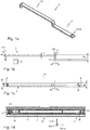
- the Figures 1b, 1c and 1d also show that the component 5 in the present case has precisely one mirror symmetry plane E1, which is arranged parallel to the longitudinal direction 1x of the guide device 1.
- a longitudinal direction 5x of the component 5 is arranged parallel to the longitudinal direction 1x of the guide device 1.
- the component 5 has a homogeneous thickness t over its entire length 5L and width 5B.
- the length 5L of the component 5 extends in the longitudinal direction 5x of the component 5.
- the width 5B of the component 5 extends in the width direction 5y of the component 5.
- the thickness t of the component 5 extends at least in sections in the height direction 5z of the component 5.
- first section 51 of the component 5 is designed linearly viewed in the longitudinal direction 5x, 1x. It is also shown that the second section 52 of the component 5, which in the present case is arranged directly adjacent to the first section 51, has a U-shape which is configured in relation to the longitudinal direction 5x of the component 5.
- the second section 52 has a total of three rounded portions 57 which form the corners of the U-shape.
- One of the rounded portions 57 is arranged directly adjacent to the first section 51 and forms the connection point to the first section 51.
- a rounded portion 57 forms a stop element 54 or 55 of the second section 52 of the component 5.
- the component 5 is designed as a sheet metal part, the production of which, with regard to the shaping, merely involves making the blank from a sheet metal and the Includes folding the blank. After that, steps to treat or refine the surface such as galvanizing or powder coating are possible.
- the component 5 has only four tabs which are bent relative to one another as manufacturing elements.
- the component 5 is therefore free of further manufacturing elements such as folds, envelopes, standing seams, beads, gills, threaded bores, weld seams and / or deep-drawn bodies.
- the component 5 apart from the recess 56 of the first section 51, the component 5 is otherwise free of further recesses.
- the width 5B of the component 5 is designed such that it changes over its length 5L and its height 5H only in the first section 51; in the present case from the maximum width 5B to the reduced width 5B '. It is thus shown that the component 5 in the first section 51 has a width 5B, 5B 'which tapers in the direction of the second section 52. In the present case, the recess 56 is arranged in a wider part of the first section 51 and not in the narrower part of the first section 51. It is also shown that the component 5 has a homogeneous width 5B ′ in the second section 52.
- the component 5 is designed to be in direct contact with a guide rail element 20 of the guide rail device 2 and at a distance from a slide rail element 30 of the slide rail device 3.
- the stop elements 4a, 4b of the slide rail device 3 are the only elements of the guide device 1 with which the stop elements 54, 55 of the component 5 interact when the slide rail device 3 is adjusted relative to the guide rail device 2.
- the Figure 2c For example, a state shortly before the first stop state, according to which the first stop element 4a of the slide rail device 3 comes to a stop with the first stop element 54 of the component 5, that is to say interacts mechanically.
- the Figure 2b For example, a second stop state, according to which the second stop element 4b of the slide rail device 3 comes to a stop with the second stop element 55 of the component 5, that is to say interacts mechanically.
Landscapes
- Engineering & Computer Science (AREA)
- Aviation & Aerospace Engineering (AREA)
- Transportation (AREA)
- Mechanical Engineering (AREA)
- Seats For Vehicles (AREA)
Abstract
Description
- Die Erfindung betrifft eine Führungseinrichtung zum Führen einer Verstellbewegung eines Fahrzeugsitzes gemäß dem Oberbegriff des Anspruchs 1.
- Beispielsweise stellt diese Verstellbewegung die Verschiebung von zueinander mittels Schieneneinrichtungen gleit- oder kugelgelagerten Elementen, also beispielsweise eines oberen Sitzteils gegenüber einem unteren Sitzteil, eines oberen Armlehnenteils gegenüber einem unteren Armlehnenteil oder eines Kopfstützenteils gegenüber einer Rückenlehne, dar. Diese Führungseinrichtungen bieten dem Benutzer eines Fahrzeugsitzes die Möglichkeit, die Position des verschiebbaren Teils oder des gesamten Sitzes abhängig von der Größe des Benutzers, von dessen Verhältnis der Beinlänge zur Rumpflänge und von dessen persönlichem Komfortempfinden anzupassen, indem das Teil oder der Sitz ausgehend von einer Grundposition in eine erste Richtung, beispielsweise nach vorne, oder in eine zur ersten Richtung bevorzugt gegenläufige zweite Richtung, also beispielsweise nach hinten, in eine angepasste Position verschiebbar und arretierbar ist. Entsprechende Arretiereinrichtungen sind aus dem Stand der Technik bekannt und werden daher im Rahmen der vorliegenden Erfindung nicht näher erläutert.
- Bekannte Schieneneinrichtungen weisen eine Führungsschieneneinrichtung und eine dazu verstellbare Gleitschieneneinrichtung auf. Ein erstes Standard-Anschlagelement der Führungsschieneneinrichtung bildet bei einer Maximalverschiebung der beiden Schieneneinrichtungen gegeneinander in die erste Verstellrichtung mit einem ersten Standard-Anschlagelement der Gleitschieneneinrichtung eine mechanische Wechselwirkung aus, so dass eine weitere Verschiebung in diese Richtung nicht möglich ist. Analog bildet ein zweites Standard-Anschlagelement der Führungsschieneneinrichtung bei einer Maximalverschiebung der beiden Schieneneinrichtungen gegeneinander in die zweite Verstellrichtung mit einem zweiten Standard-Anschlagelement der Gleitschieneneinrichtung eine mechanische Wechselwirkung aus, so dass eine weitere Verschiebung in diese Richtung ebenfalls nicht möglich ist.
- Allerdings spielen neben den Proportionen des Fahrers und der gewünschten Bequemlichkeit auch die im Fahrzeug gegebenen Platzverhältnisse eine Rolle. So kann es zum Beispiel sein, dass ein Fahrzeugsitz durch eine maximale Verstellung nach vorne so weit vorne im Fahrzeug positioniert ist, dass ein sehr großer Fahrer mit seinen Knien am Lenkrad anstößt. Weiterhin ist es beispielsweise möglich, dass Bauteile eines derartigen Fahrzeugsitzes bei maximaler Verstellung nach hinten mit einer oder mehreren Scheiben des Fahrzeugs kollidieren. Dies ist insbesondere dann möglich, wenn die Fahrerkabine dieses Fahrzeugs sehr eng bemessen ist, wie zum Beispiel eine Fahrerkabine eines Baggers.
- Es ist also sinnvoll, bei Fahrzeugsitzen den maximalen Verstellweg in die möglichen Verstellrichtungen individuell begrenzbar zu gestalten.
- Gerade für die Schieneneinrichtungen werden im Fahrzeugbau jedoch oft Zukaufteile verwendet, die in hohen Stückzahlen produziert werden und dementsprechend günstig eingekauft werden können. Eine individuelle Änderung der Bauform oder der Gestaltung dieser Schieneneinrichtungen zur Sicherstellung der Begrenzung des Verstellwegs ist daher in der Kalkulation des Verkaufspreises nicht vorgesehen und würde den Fahrzeugsitz bzw. das Fahrzeug selbst über Gebühr verteuern.
- Es ist also praktikabler, die Gestaltung der Verstelleinrichtung eines Fahrzeugsitzes, so dass der maximale Verstellweg in eine oder beide Richtungen individuell begrenzbar ausgestaltet ist, so vorzunehmen, dass für die Führungseinrichtung weiterhin eine Standardbaugruppe verwendet werden kann, die jedoch einfach durch geeignete Vorrichtungen ergänzt wird.
- Hierzu ist aus dem Stand der Technik bekannt, ein Bauteil vorzusehen, welches in die Führungseinrichtung eingebaut wird und die Verschiebung in die erste Richtung begrenzt. Zusätzlich ist allerdings ein zweites Bauteil notwendig, welches ebenfalls in die Führungseinrichtung eingebaut wird und die Verschiebung in die zweite Richtung begrenzt. Es versteht sich, dass diese Lösung mit zwei Bauteilen mit einem hohen Montageaufwand einhergeht und daher die Kosten in die Höhe treibt.
- Es ist daher Aufgabe vorliegender Erfindung, eine Führungseinrichtung zur Verfügung zu stellen, welche eine Möglichkeit aufweist, den maximalen Verstellweg beider Schieneneinrichtungen zueinander in beide Richtungen individuell zu begrenzen, und deren Vormontage einfach zu bewerkstelligen ist.
- Diese Aufgabe wird gelöst gemäß den Merkmalen des Anspruches 1.
- Es wird demnach eine Führungseinrichtung zum Führen einer Verstellbewegung eines Fahrzeugsitzes vorgeschlagen, umfassend eine Führungsschieneneinrichtung und eine dazu in eine Längsverstellrichtung der Führungseinrichtung verschiebbar angeordnete Gleitschieneneinrichtung, wobei die Gleitschieneneinrichtung ein erstes Anschlagelement und ein zweites Anschlagelement aufweist. Ferner ist ein einstückiges Bauteil zwischen der Gleitschieneneinrichtung und der Führungsschieneneinrichtung angeordnet, welches in Längsrichtung der Führungseinrichtung in einen ersten und einen zweiten Abschnitt unterteilt ist, wobei das Bauteil mittels zumindest eines im ersten Abschnitt angeordneten Verbindungselements fest mit der Führungsschieneneinrichtung verbunden ist. Erfindungsgemäß bildet der zweite Abschnitt des Bauteils an einem ersten Ende ein erstes Anschlagelement für eines der Anschlagelemente der Gleitschieneneinrichtung und an einem zweiten Ende ein zweites Anschlagelement für das andere der Anschlagelemente der Gleitschieneneinrichtung aus.
- Bevorzugt handelt es sich bei der Führungsschieneneinrichtung und der dazugehörigen Gleitschieneneinrichtung um Kugelschieneneinrichtungen im Sinne von zueinander kugelgelagerten Linearschienen, so dass insgesamt eine Kugelschienenführungseinheit vorliegt. Diese Ausführungsform ist für eine reibungsarme Relativbewegung der beiden Schienen besonders geeignet.
- Bevorzugt ist ein Rest der Führungseinrichtung auch ohne eingesetztes Bauteil bereits eine vollständige Baugruppe und/oder hinsichtlich der Relativbewegung der beiden Schieneneinrichtungen vollständig funktionsfähig. Das Bauteil ist somit bevorzugt nicht als Teil der Führungsschieneneinrichtung und/oder der Gleitschieneneinrichtung, sondern bevorzugt unabhängig davon ausgestaltet.
- Durch das angeordnete Bauteil ist einerseits gewährleistet, dass weiterhin standardmäßig eingebaute Gleitschieneneinrichtungen und Führungsschieneneinrichtungen für die Führungseinrichtung verwendet werden können. Andererseits kann vorteilhaft das Bauteil nachgerüstet werden, so dass insbesondere dann, wenn ein Fahrerwechsel ansteht oder sich die Kundenwünsche nachträglich noch ändern, eine schnelle und kostengünstige Lösung zur Änderung der Begrenzung der Verstellwege bereitgestellt werden kann. Insbesondere ist das Bauteil nachträglich in den Rest der bereits fertig vormontierte Führungseinrichtung einsetzbar.
- Bevorzugt ist das Bauteil so ausgestaltet, dass zum Einsetzen des Bauteils ("Einfädeln") in die Führungseinrichtung das Bauteil lediglich eine Translation in Längsrichtung der Führungseinrichtung sowie eine Rotation um eine Achse in Breitenrichtung der Führungseinrichtung erfährt.
- Die Anschlagelemente der Gleitschieneneinrichtung stellen jedoch vorteilhaft nicht die Standard-Anschlagelemente dar, die ohne einsetzbares Bauteil im Zusammenspiel mit den Anschlagelementen der Führungsschieneneinrichtung für die Begrenzung der Verstellwege zuständig sind.
- Zur besseren Unterscheidung werden in dem Fall, dass kein Bauteil in die Führungseinrichtung eingesetzt ist, die miteinander wechselwirkbaren Anschlagelemente von Gleitschieneneinrichtung und Führungsschieneneinrichtung als "Standard-Anschlagelemente" bezeichnet. Analog dazu werden in dem Fall, dass ein Bauteil in die Führungseinrichtung eingesetzt ist, die miteinander wechselwirkbaren Anschlagelemente von Gleitschieneneinrichtung und Bauteil als "Anschlagelemente" bezeichnet.
- Vorteilhaft sind die mit den Anschlagelementen des Bauteils wechselwirkbaren Anschlagelemente der Gleitschieneneinrichtung ebenfalls Teil der Standard- Führungseinrichtung und beispielsweise als Teil von Schraubenverbindungen ausgestaltet. Die Schraubenverbindungen sind vorteilhaft zum Verbinden der Gleitschieneneinrichtung mit einem zu verschiebenden Oberteil bereitgestellt.
- Gemäß einer bevorzugten Ausführungsform sind die Standard-Anschlagelemente der Gleitschieneneinrichtung und der Führungsschieneneinrichtung so angeordnet, dass sie in Breitenrichtung der Führungseinrichtung zentral oder beidseits symmetrisch zur Mittelachse der Führungseinrichtung angeordnet sind. Dies gewährleistet, dass die Schieneneinrichtungen beim Anschlag der Standard-Anschlagelemente sich nicht ohne Weiteres verkanten können.
- Gleichzeitig ist von einer sicheren und mechanisch stabilen Führung und Begrenzung der Verstellwege auszugehen.
- Dabei ist durch die Anordnung der Standard-Anschlagelemente gewährleistet, dass immer nur die gleichen Standard-Anschlagelemente miteinander wechselwirkbar sind. Betrachtet wird nun die Führungseinrichtung ohne einsetzbares Bauteil. Es ist also beispielsweise ausgeschlossen, dass ein Standard-Anschlagelement der Führungsschieneneinrichtung, das für die Begrenzung des Verstellwegs in die erste Richtung zuständig ist, mit einem Standard-Anschlagelement der Gleitschieneneinrichtung, das für die Begrenzung des Verstellwegs in die zweite Richtung zuständig ist, wechselwirkt. Das gleiche gilt natürlich für den umgekehrten Fall. Alle zur Führungseinrichtung gehörenden Standard-Anschlagelemente sind also bevorzugt in Längsrichtung der Führungseinrichtung gesehen hintereinander angeordnet.
- Beispielsweise sind in Längsrichtung der Führungseinrichtung betrachtet die Standard-Anschlagelemente der Führungsschieneneinrichtung, die den Verstellweg in die erste Richtung begrenzen, in einem ersten Endbereich der Führungsschieneneinrichtung angeordnet, wohingegen beispielsweise die Standard-Anschlagelemente, die den Verstellweg in die zweite Richtung begrenzen, in einem zweiten Endbereich der Führungsschieneneinrichtung angeordnet sind.
- Analog dazu sind in Längsrichtung der Führungseinrichtung betrachtet die Standard-Anschlagelemente der Gleitschieneneinrichtung, die den Verstellweg in die erste Richtung begrenzen, in einem ersten mittleren Bereich angeordnet, wohingegen beispielsweise die Standard-Anschlagelemente, die den Verstellweg in die zweite Richtung begrenzen, in einem zweiten mittleren Bereich angeordnet sind.
- Dabei sind die zur Führungsschieneneinrichtung gehörenden Standard-Anschlagelemente aus dem ersten Endbereich mit den zur Gleitschieneneinrichtung gehörenden Standard-Anschlagelementen aus dem ersten mittleren Bereich wechselwirkbar. Analog dazu sind die zur Führungsschieneneinrichtung gehörenden Standard-Anschlagelemente aus dem zweiten Endbereich mit den zur Gleitschieneneinrichtung gehörenden Standard-Anschlagelementen aus dem zweiten mittleren Bereich wechselwirkbar; zumindest dann, wenn kein Bauteil gemäß Anspruch 1 eingesetzt ist.
- Das angeordnete Bauteil übernimmt also die Begrenzung des Verstellwegs in die erste Richtung und gleichzeitig in die zweite Richtung. Zudem kann es über das Verbindungselement im ersten Abschnitt, welches als Teil des Bauteils, beispielsweise als Aussparung des Bauteils und bevorzugt als Durchgangsbohrung, ausgestaltet ist, mechanisch sicher in die Führungsschiene eingebaut werden.
- Im Sinne der vorliegenden Erfindung sind die Anschlagelemente der Gleitschieneneinrichtung bevorzugt als mechanische Stoppelemente ausgebildet, welche in einen Einbauraum, welcher bevorzugt als Zwischenraum zwischen einem Gleitschienenelement der Gleitschieneneinrichtung und einem Führungsschienenelement der Führungsschieneneinrichtung ausgestaltet ist, hineinragend angeordnet sind.
- Bevorzugt umfasst das Bauteil genau einen ersten Abschnitt und genau einen zweiten Abschnitt. Bevorzugt ist das Bauteil ansonsten frei von weiteren Abschnitten.
- Gemäß einer bevorzugten Ausführungsform weist das Bauteil genau eine Spiegelsymmetrieebene auf, welche bevorzugt parallel zur Längsrichtung der Führungseinrichtung angeordnet ist. Das Bauteil ist also einfach gestaltet; seine Montage innerhalb der Führungseinrichtung kann intuitiv gelingen, da die Anordnung der Spiegelsymmetrieebene in Relation zur Längsrichtung der Führungseinrichtung selbsterklärend ist. Außerdem ist durch die Spiegelsymmetrieebene und deren Anordnung parallel zur Längsrichtung der Führungseinrichtung gewährleistet, dass es zwei Möglichkeiten gibt, das Bauteil einzubauen. Diese beiden Möglichkeiten und die daraus resultierenden Einbauzustände werden nachfolgend noch genauer erläutert.
- Bevorzugt ist eine Längsrichtung des Bauteils zumindest in einem, bevorzugt in beiden seiner in die Führungseinrichtung eingebauten Zustände parallel zur Längsrichtung der Führungseinrichtung angeordnet. Gleiches gilt bevorzugt für eine Breitenrichtung des Bauteils in Bezug auf die Breitenrichtung der Führungseinrichtung sowie für eine Höhenrichtung des Bauteils in Bezug auf die Höhenrichtung der Führungseinrichtung. Bevorzugt ist das Bauteil hinsichtlich einer Breitenrichtung der Führungseinrichtung mittig angeordnet, so dass es mittig zur Breite der Führungsschieneneinrichtung, des Führungsschienenelements, der Gleitschieneneinrichtung und/oder des Gleitschienenelements angeordnet ist.
- Außerdem ist es bevorzugt, wenn das Bauteil insgesamt eine einfache Gestaltung aufweist. So ist es beispielsweise bevorzugt, dass das Bauteil über seine gesamte Länge und/oder Breite eine homogene Dicke aufweist. Es kann außerdem vorgesehen sein, dass der erste Abschnitt des Bauteils in Längsrichtung gesehen linear ausgestaltet ist.
- Denkbar ist natürlich, dass verschiedene Bauteile bereitgestellt werden, welche sich hinsichtlich der Länge des ersten und/oder des zweiten Abschnitts unterscheiden. Je nach Kundenwunsch wird dann das passende Bauteil ausgesucht und eingesetzt.
- Ferner kann vorgesehen sein, dass der zweite Abschnitt des Bauteils, welcher bevorzugt unmittelbar benachbart zum ersten Abschnitt angeordnet ist, eine U-Form aufweist. Bevorzugt ist diese U-Form in Bezug auf die Längsrichtung des Bauteils ausgestaltet.
- Bevorzugt erstreckt sich die Länge des Bauteils in Längsrichtung des Bauteils. Bevorzugt erstreckt sich die Breite des Bauteils in Breitenrichtung des Bauteils. Bevorzugt erstreckt sich die Dicke des Bauteils zumindest abschnittsweise in Höhenrichtung des Bauteils.
- Unter "U-Form" wird im Rahmen der vorliegenden Erfindung verstanden, dass das Element, hier der zweite Abschnitt, einen zentralen linearen Anteil aufweist, und dass unmittelbar benachbart zum zentralen Anteil zwei dazu senkrecht verlaufende Anteile angeordnet sind.
- Gegebenenfalls kann der zweite Abschnitt gerundete Abschnitte aufweisen, welche die Ecken der U-Form und/oder die Verbindungsstelle zum ersten Abschnitt hin ausbilden.
- Bevorzugt bilden jeweils ein senkrechter Anteil oder ein gerundeter Anteil oder jeweils ein senkrechter Anteil zusammen mit jeweils einem gerundeten Anteil jeweils ein Anschlagelement des zweiten Abschnitts des Bauteils aus.
- Das Bauteil kann insbesondere als ein Blechteil ausgestaltet sein, dessen Fertigung hinsichtlich der Formgebung lediglich das Anfertigen des Zuschnitts aus einer Blechtafel sowie das Abkanten des Zuschnitts umfasst. Danach sind noch oberflächenbehandelnde oder -veredelnde Schritte wie Verzinken oder Pulverbeschichten möglich.
- Das Bauteil weist also bevorzugt lediglich zueinander abgekantete Laschen ("Abkantungen"), bevorzugt lediglich vier, als Fertigungselemente auf. Das Bauteil ist also bevorzugt frei von weiteren Fertigungselementen wie Falzen, Umschlägen, Stehfalzen, Sicken, Kiemen, Gewindebohrungen, Schweißnähten und/oder Tiefziehkörpern.
- Um die Kosten weiter zu senken, ist es vorteilhaft, wenn mittels eines einzelnen Bauteils pro Führungseinrichtung insgesamt zwei verschieden große Begrenzungen des Verstellwegs realisierbar sind.
- Gemäß einer weiteren bevorzugten Ausführungsform ist demnach vorgesehen, dass die Längsverstellrichtung der Führungseinrichtung eine Richtung nach vorne und/oder eine Richtung nach hinten ist. Bevorzugt gibt es mindestens einen ersten und mindestens einen zweiten Einbauzustand des Bauteils. Beispielsweise ist gemäß dem ersten Einbauzustand in Bezug auf die Längsverstellrichtung nach vorne der erste Abschnitt des Bauteils vor dem zweiten Abschnitt angeordnet. Beispielsweise ist gemäß dem zweiten Einbauzustand in Bezug auf die Längsverstellrichtung nach vorne der erste Abschnitt des Bauteils hinter dem zweiten Abschnitt angeordnet.
- Es versteht sich, dass "vorne" und "hinten" Richtungen darstellen, welche auf die Führungseinrichtung bezogen sind. Diese Richtungen können auch den Richtungen des gesamten Sitzes oder eines Sitzoberteils entsprechen, müssen es jedoch nicht.
- Das Bauteil kann also hinsichtlich der Längsverstellrichtung der Führungseinrichtung zwei Orientierungen aufweisen, welche zueinander um 180° gedreht sind. Bevorzugt sind die Orientierungen zueinander um 180° bezüglich einer Achse in Höhenrichtung der Führungseinrichtung gedreht. Die Relativposition des zweiten Abschnitts des Bauteils zum Rest der Führungseinrichtung und somit zu den Anschlagelementen unterscheidet sich bevorzugt vom ersten zum zweiten Einbauzustand. Damit ist es möglich, zwei unterschiedlich große Verstellwege mit einem einzelnen Bauteil je Führungseinrichtung zu realisieren.
- Es ist vorteilhaft, wenn die Position des Bauteils in jedem Einbauzustand zumindest stufenbehaftet nochmals verstellbar ist, um weitere Verstellmöglichkeiten zu realisieren. Beispielsweise ist es bevorzugt, dass das Bauteil im ersten Abschnitt mindestens eine, bevorzugt mehrere Aussparungen aufweist, wobei es mittels mindestens einer der Aussparungen mit mindestens einem Befestigungselement der Führungsschieneneinrichtung verbindbar ist. Beispielsweise sind diese Aussparungen in Längsrichtung des Bauteils aufeinanderfolgend angeordnet. Der Abstand zwischen den Aussparungen kann dabei jeweils identisch oder unterschiedlich sein.
- Bevorzugt ist das Bauteil gemäß beiden Einbauzuständen in die Führungsschieneneinrichtung einbaubar, wobei pro Einbauzustand für die Ausbildung des Verbindungselements zur Führungsschieneneinrichtung zwischen einer oder mehreren, bevorzugt zwischen allen Aussparungen des Bauteils gewählt werden kann.
- Es ist ferner vorteilhaft, wenn die Position des Bauteils in jedem Einbauzustand stufenlos verstellbar ist. Es ist beispielsweise denkbar, dass zumindest eine der Aussparungen als Langloch ausgebildet ist.
- Bevorzugt ist das Bauteil abgesehen von der oder den Aussparungen des ersten Abschnitts ansonsten frei von weiteren Aussparungen. Dies erhöht die Stabilität des Bauteils.
- Bevorzugt ist die Breite des Bauteils so ausgestaltet, dass sie sich über seine Länge und/oder Höhe nicht oder lediglich im ersten Abschnitt ändert. Um für die Montage des Bauteils innerhalb der Führungseinrichtung und das Anbringen der dafür vorgesehenen Aussparung genügend Platz ("Fleisch") bereitzustellen und gleichzeitig für eine Leichtbauweise des Bauteils zu sorgen, kann es vorteilhaft sein, wenn das Bauteil im ersten Abschnitt eine sich in Richtung zum zweiten Abschnitt hin verjüngende Breite aufweist. Bevorzugt ist die oder sind die Aussparungen in einem breiteren Teil des ersten Abschnitts und/oder nicht im schmaleren Teil des ersten Abschnitts angeordnet.
- Ferner kann es vorteilhaft sein, wenn das Bauteil im zweiten Abschnitt eine homogene Breite aufweist. Ferner kann es vorteilhaft sein, wenn das Bauteil im zweiten Abschnitt einen sich gegenüber der restlichen Breite des zweiten Abschnitts verbreiternden Endabschnitt aufweist. Damit wird die Stabilität des Bauteils erhöht.
- Um eine sichere Montage des Bauteils innerhalb der Führungsschieneneinrichtung und gleichzeitig die ungehinderte Verschiebung der Gleitschieneneinrichtung relativ zur Führungsschieneneinrichtung zu gewährleisten, ist es bevorzugt, dass das Bauteil unmittelbar kontaktierend zu einem Führungsschienenelement der Führungsschieneneinrichtung und/oder beabstandet zu einem Gleitschienenelement der Gleitschieneneinrichtung ausgebildet ist. Es ist bevorzugt, dass die Anschlagelemente der Gleitschieneneinrichtung die einzigen Elemente der Führungseinrichtung sind, mit denen die Anschlagelemente des Bauteils bei einer Verstellung der Gleitschieneneinrichtung relativ zur Führungsschieneneinrichtung wechselwirkbar sind.
- Eine derartige Führungseinrichtung könnte an einem Fahrzeugsitz und/oder innerhalb eines Fahrzeugs beispielsweise so angeordnet sein, dass die Längsverstellrichtung der Führungseinrichtung parallel zu einer Längsrichtung des Fahrzeugsitzes und/oder des Unterteils des Fahrzeugsitzes anordenbar ist, und dass die Führungsschieneneinrichtung mit dem Unterteil des Fahrzeugsitzes und die Gleitschieneneinrichtung mit einem Oberteil des Fahrzeugsitzes fest verbindbar sind.
- Weitere Vorteile, Ziele und Eigenschaften vorliegender Erfindung werden anhand anliegender Zeichnung und nachfolgender Beschreibung erläutert, in welchen beispielhaft Ausführungsformen des verwendeten Bauteils und der erfindungsgemäßen Führungseinrichtung dargestellt und beschrieben ist. In der Zeichnung zeigen:
- Figur 1a-c
- schematisch mehrere Ansichten eines Bauteils zum Einsetzen in einer Führungseinrichtung gemäß einer ersten Ausführungsform;
- Figur 1d
- schematisch eine Ansicht einer erfindungsgemäßen Führungseinrichtung mit eingesetztem Bauteil;
- Figur 2a-c
- verschiedene Stadien eines Montagevorgangs des Bauteils aus der
Figur 1a in eine Führungseinrichtung, so dass das Bauteil gemäß einem ersten Einbauzustand montiert ist; - Figur 3a-c
- verschiedene Stadien eines Montagevorgangs des Bauteils aus der
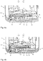
Figur 1a in eine Führungseinrichtung, so dass das Bauteil gemäß einem zweiten Einbauzustand montiert ist; - Figur 4a
- eine schräge Ansicht der Baugruppe gemäß der
Fig. 2c ; - Figur 4b
- eine schräge Ansicht der Baugruppe gemäß der
Fig. 3c ; - Fig. 5a
- eine Ansicht von vorne von Teilen eines Fahrzeugsitzes mit einer erfindungsgemäßen Führungseinrichtung;
- Fig. 5b
- eine vergrößerte Ansicht gemäß
Fig. 5a . - Es sei erwähnt, dass zur besseren Übersichtlichkeit bei den Figuren Teile weggelassen wurden. So zeigen beispielsweise die
Figuren 4a und 4b nur ein Unterteil SU eines Fahrzeugsitzes S und dieFigur 5a nicht den gesamten Fahrzeugsitz S, sondern nur Teile davon. DieFigur 1d zeigt nur Teile der Führungseinrichtung 1 und insbesondere nicht die Führungsschieneneinrichtung 2 der Führungseinrichtung 1. - Die Erfindung wird im Folgenden anhand einer Führungseinrichtung 1 zum Führen einer Verstellbewegung eines Fahrzeugsitzes S beschrieben, wobei die Verstellbewegung beispielhaft die Verschiebung eines oberen Sitzteils SO gegenüber einem unteren Sitzteil SU darstellt. Dazu ist wie abgebildet vorliegend das obere Sitzteil SO mit der Gleitschieneneinrichtung 3 und das untere Sitzteil SU mit der Führungsschieneneinrichtung 2 fest verbunden.
- Gezeigt sind beispielsweise anhand der
Figuren 2a-c ,3a-c und 5a ,5b Teile eines Fahrzeugsitzes S, wobei eine Führungseinrichtung 1 mit der Führungsschieneneinrichtung 2 und der dazu verstellbaren Gleitschieneneinrichtung 3 dargestellt ist. - Ein Koordinatensystem in der
Figur 5a verdeutlicht die Orientierung der Längsrichtung 1xa der Führungseinrichtung 1 nach vorne, der Breitenrichtung 1y der Führungseinrichtung 1 nach rechts sowie der Höhenrichtung 1z der Führungseinrichtung 1 nach oben. Vorliegend ist die Führungseinrichtung 1 innerhalb des Fahrzeugsitzes S so angeordnet, dass die Längsrichtung 1xa der Führungseinrichtung 1 der Sitzlängsrichtung Sx, die Breitenrichtung 1y der Führungseinrichtung 1 der Sitzbreitenrichtung Sy und die Höhenrichtung 1z der Sitzhöhenrichtung Sz entsprechen. - Gemäß
Fig. 5a und 5b ist die Gleitschieneneinrichtung 3 in einer Grundstellung angeordnet, gemäß welcher die Gleitschieneneinrichtung 3 und die Führungsschieneneinrichtung 2 zueinander nicht verschoben angeordnet sind. Insbesondere sind gemäß dieser Grundstellung gleich orientierte Stirnflächen des Gleitschienenelements 30 und des Führungsschienenelements 20 in Bezug auf die Längsrichtung 1x der Führungseinrichtung 1 an der gleichen Position angeordnet.Fig. 5b zeigt dabei eine Vergrößerung eines Ausschnitts A' gemäßFig. 5a . - Ein erstes Standard-Anschlagelement 7a der Führungsschieneneinrichtung 2 bildet bei einer Maximalverschiebung der beiden Schieneneinrichtungen 2, 3 gegeneinander in die erste Verstellrichtung 1xa mit einem ersten Standard-Anschlagelement 8a der Gleitschieneneinrichtung 3 eine mechanische Wechselwirkung aus, so dass eine weitere Verschiebung in diese Richtung 1xa nicht möglich ist. Dieser Fall gilt, wenn kein Bauteil 5 in die Führungseinrichtung 1 eingesetzt ist.
- Analog bildet ein zweites Standard-Anschlagelement 7b der Führungsschieneneinrichtung 2 bei einer Maximalverschiebung der beiden Schieneneinrichtungen 2, 3 gegeneinander in die zweite Verstellrichtung 1xb mit einem zweiten Standard-Anschlagelement 8b der Gleitschieneneinrichtung 3 eine mechanische Wechselwirkung aus, so dass eine weitere Verschiebung in diese Richtung 1xb ebenfalls nicht möglich ist. Vorliegend sind die Standard-Anschlagelemente 7a, 7b, 8a, 8b jeweils als "Nasen", also als umgekantete Laschen eines Führungsschienenelements 20 der Führungsschieneneinrichtung 2 und eines Gleitschienenelements 30 der Gleitschieneneinrichtung 3 ausgestaltet. Dieser Fall gilt ebenfalls dann, wenn kein Bauteil 5 in die Führungseinrichtung 1 eingesetzt ist.
- Gezeigt ist insbesondere gemäß der
Figur 2b eine Führungseinrichtung 1 zum Führen einer Verstellbewegung eines Fahrzeugsitzes S, umfassend eine Führungsschieneneinrichtung 2 und eine dazu in eine Längsverstellrichtung 1x der Führungseinrichtung 1 verschiebbar angeordnete Gleitschieneneinrichtung 3, wobei die Gleitschieneneinrichtung 3 ein erstes Anschlagelement 4a und ein zweites Anschlagelement 4b aufweist. Ebenfalls ist ein einstückiges Bauteil 5 zwischen der Gleitschieneneinrichtung 3 und der Führungsschieneneinrichtung 2 angeordnet, welches in Längsrichtung 1x der Führungseinrichtung 1, welche vorliegend der Längsrichtung des Bauteils 5 entspricht, in einen ersten 51 und einen zweiten Abschnitt 52 unterteilt ist. Das Bauteil 5 ist mittels eines im ersten Abschnitt 51 angeordneten Verbindungselements 53 fest mit der Führungsschieneneinrichtung 2, vorliegend mittels des Befestigungselements 6b der Führungsschieneneinrichtung 2, verbunden. - Dabei bildet der zweite Abschnitt 52 des Bauteils 5 an einem ersten Ende 52a ein erstes Anschlagelement 54 für das erste Anschlagelement 4a der Gleitschieneneinrichtung 3 und an einem zweiten Ende 52b ein zweites Anschlagelement 55 für das zweite Anschlagelement 4b der Gleitschieneneinrichtung 3 aus. Gemäß der
Figur 3c bildet der zweite Abschnitt 52 des Bauteils 5 am ersten Ende 52a ein erstes Anschlagelement 54 für das zweite Anschlagelement 4b der Gleitschieneneinrichtung 3 und an einem zweiten Ende 52b ein zweites Anschlagelement 55 für das erste Anschlagelement 4a der Gleitschieneneinrichtung 3 aus. - Das Bauteil 5 ist vorliegend nicht als Teil der Führungsschieneneinrichtung 2 und/oder der Gleitschieneneinrichtung 3, sondern unabhängig davon ausgestaltet. Gemäß der
Fig. 1d ist ein Blick von unten, also parallel zur Höhenrichtung 1z, auf die Führungseinrichtung 1 dargestellt, wobei zur besseren Übersichtlichkeit die Führungsschieneneinrichtung 2 ausgeblendet ist. Vorliegend ist das Bauteil 5 hinsichtlich einer Breitenrichtung 1y der Führungseinrichtung 1 mittig angeordnet, so dass es mittig zur Breite der Führungsschieneneinrichtung 2, des Führungsschienenelements 20, der Gleitschieneneinrichtung 3 und des Gleitschienenelements 30 angeordnet ist. - Vorliegend ist das Bauteil 5 so ausgestaltet, dass zum Einsetzen des Bauteils 5 ("Einfädeln") in die Führungseinrichtung 1 das Bauteil 5 lediglich eine Translation in Längsrichtung 1x der Führungseinrichtung 1 sowie eine Rotation um eine Achse in Breitenrichtung 1y der Führungseinrichtung 1 erfährt.
- Die
Figuren 2a-c zeigen verschiedene Schritte in chronologischer Reihenfolge des Einfädelns des Bauteils 5 in den Rest der Führungseinrichtung 1, so dass das Bauteil 5 gemäß einem ersten Einbauzustand A eingebaut ist. - Gemäß
Fig. 2a ist ein erster Schritt des Einfädelns zu sehen. Demnach ist die Gleitschieneneinrichtung 3 und mit ihr das obere Sitzteil SO maximal gegenüber der Führungsschieneneinrichtung 2 und dem unteren Sitzteil SU nach hinten 1xb verschoben. So ist gewährleistet, dass das hintere Anschlagelement 4b der Gleitschieneneinrichtung 3 beim Einfädeln des Bauteils 5 nicht mit dem Bauteil 5 kollidiert. Das Bauteil 5 wird nun von der hinteren Sitzseite aus in Längsrichtung nach vorne 1xa mit dem zweiten Abschnitt 52 zuerst in den Einbauraum 9 geschoben. - Gemäß
Fig. 2b hat das Bauteil 5 bereits seine angedachte Position innerhalb des Rests der Führungseinrichtung 1 erreicht. Die Gleitschieneneinrichtung 3 wird nun maximal nach vorne 1xa verschoben, damit der zum Befestigen des Bauteils 5 innerhalb des Rests der Führungseinrichtung 1 notwendige Zugang zum Befestigungselement 6b der Führungsschieneneinrichtung 2 gewährleistet wird. Mittels des Befestigungselements 6b und des Verbindungselements 53 wird das Bauteil 5 über die Führungsschieneneinrichtung 2 an dem unteren Sitzteil SU befestigt. DieFig. 2c zeigt den Zustand, gemäß welchem die Führungseinrichtung 1 komplett ist und die Montage des Bauteils 5 beendet ist. - Mittels des gezeigten Bauteils 5 sind allerdings insgesamt zwei verschieden große Begrenzungen des Verstellwegs realisierbar.
- Vorliegend kann die Längsverstellrichtung 1x der Führungseinrichtung 1 eine Richtung nach vorne 1xa und eine Richtung nach hinten 1xb sein. Es gibt mindestens einen ersten A und mindestens einen zweiten Einbauzustand B des Bauteils 5. So zeigen die
Figuren 2a-c den ersten Einbauzustand A, gemäß welchem in Bezug auf die Längsverstellrichtung 1x nach vorne 1ax der erste Abschnitt 51 des Bauteils 5 vor dem zweiten Abschnitt 52 angeordnet ist. Außerdem zeigen dieFiguren 3a-c den zweiten Einbauzustand B, gemäß welchem in Bezug auf die Längsverstellrichtung 1x nach vorne 1ax der erste Abschnitt 51 des Bauteils 5 hinter dem zweiten Abschnitt 52 angeordnet ist. - Die
Figuren 3a-c zeigen verschiedene Schritte in chronologischer Reihenfolge des Einfädelns des Bauteils 5 in den Rest der Führungseinrichtung 1, so dass das Bauteil 5 gemäß einem zweiten Einbauzustand B eingebaut ist. - Gemäß
Fig. 3a ist ein erster Schritt des Einfädelns zu sehen. Demnach ist die Gleitschieneneinrichtung 3 und mit ihr das obere Sitzteil SO maximal gegenüber der Führungsschieneneinrichtung 2 und dem unteren Sitzteil SU nach vorne 1xa verschoben. So ist gewährleistet, dass das vordere Anschlagelement 4a der Gleitschieneneinrichtung 3 beim Einfädeln des Bauteils 5 nicht mit dem Bauteil 5 kollidiert. Das Bauteil 5 wird nun von der vorderen Sitzseite aus in Längsrichtung nach hinten 1xb mit dem zweiten Abschnitt 52 zuerst in den Einbauraum 9 geschoben. - Gemäß
Fig. 3c hat das Bauteil 5 bereits seine angedachte Position innerhalb des Rests der Führungseinrichtung 1 erreicht. Die Gleitschieneneinrichtung 3 wird nun maximal nach hinten 1xb verschoben, damit der zum Befestigen des Bauteils 5 innerhalb des Rests der Führungseinrichtung 1 notwendige Zugang zum Befestigungselement 6a der Führungsschieneneinrichtung 2 gewährleistet wird. Mittels des Befestigungselements 6a (wovon hier Teile, nämlich die Schraube des Befestigungselements 6a, ausgeblendet sind; gezeigt ist nur die Bohrung des Befestigungselements 6a) und des Verbindungselements 53 wird das Bauteil 5 über die Führungsschieneneinrichtung 2 an dem unteren Sitzteil SU befestigt. - Vorliegend sind die mit den Anschlagelementen 54, 55 des Bauteils 5 wechselwirkbaren Anschlagelemente 4a, 4b der Gleitschieneneinrichtung 3 ebenfalls Teil der Standard-Führungsschiene und beispielsweise als Teil von Schraubenverbindungen, vorliegend als Sechskantmuttern, ausgestaltet. Diese Schraubenverbindungen sind vorliegend zum Verbinden der Gleitschieneneinrichtung 3 mit einem zu verschiebenden Oberteil, hier dem oberen Sitzteil SO, bereitgestellt.
- Vorliegend sind die Anschlagelemente 4a, 4b der Gleitschieneneinrichtung 3 als mechanische Stoppelemente ausgebildet, welche in einen Einbauraum 9 (siehe
Fig. 5b ), welcher vorliegend als Zwischenraum zwischen dem Gleitschienenelement 30 der Gleitschieneneinrichtung 3 und einem Führungsschienenelement 20 der Führungsschieneneinrichtung 2 ausgestaltet ist, hineinragend angeordnet sind. - Vorliegend umfasst das Bauteil 5 genau einen ersten Abschnitt 51 und genau einen zweiten Abschnitt 52 und ist ansonsten frei von weiteren Abschnitten.
- Die
Figuren 1b, 1c und 1d zeigen außerdem, dass das Bauteil 5 vorliegend genau eine Spiegelsymmetrieebene E1 aufweist, welche parallel zur Längsrichtung 1x der Führungseinrichtung 1 angeordnet ist. Vorliegend ist eine Längsrichtung 5x des Bauteils 5 parallel zur Längsrichtung 1x der Führungseinrichtung 1 angeordnet. Gleiches gilt vorliegend für eine Breitenrichtung 5y des Bauteils 5 in Bezug auf die Breitenrichtung 1y der Führungseinrichtung 1 sowie für eine Höhenrichtung 5z des Bauteils 5 in Bezug auf die Höhenrichtung 1z der Führungseinrichtung 1. - Außerdem ist gezeigt, dass das Bauteil 5 über seine gesamte Länge 5L und Breite 5B eine homogene Dicke t aufweist. Vorliegend erstreckt sich die Länge 5L des Bauteils 5 in Längsrichtung 5x des Bauteils 5. Vorliegend erstreckt sich die Breite 5B des Bauteils 5 in Breitenrichtung 5y des Bauteils 5. Vorliegend erstreckt sich die Dicke t des Bauteils 5 zumindest abschnittsweise in Höhenrichtung 5z des Bauteils 5.
- Gezeigt ist, dass der erste Abschnitt 51 des Bauteils 5 in Längsrichtung 5x, 1x gesehen linear ausgestaltet ist. Ferner ist gezeigt, dass der zweite Abschnitt 52 des Bauteils 5, welcher vorliegend unmittelbar benachbart zum ersten Abschnitt 51 angeordnet ist, eine U-Form aufweist, welche in Bezug auf die Längsrichtung 5x des Bauteils 5 ausgestaltet ist.
- Vorliegend weist der zweite Abschnitt 52 insgesamt drei gerundete Anteile 57 auf, welche die Ecken der U-Form ausbilden. Einer der gerundeten Anteile 57 ist unmittelbar benachbart zum ersten Abschnitt 51 angeordnet und bildet die Verbindungsstelle zum ersten Abschnitt 51 hin aus.
- Vorliegend bildet jeweils ein gerundeter Anteil 57 jeweils ein Anschlagelement 54 oder 55 des zweiten Abschnitts 52 des Bauteils 5 aus.
- Das Bauteil 5 ist vorliegend als ein Blechteil ausgestaltet, dessen Fertigung hinsichtlich der Formgebung lediglich das Anfertigen des Zuschnitts aus einer Blechtafel sowie das Abkanten des Zuschnitts umfasst. Danach sind noch oberflächenbehandelnde oder -veredelnde Schritte wie Verzinken oder Pulverbeschichten möglich.
- Das Bauteil 5 weist vorliegend lediglich vier zueinander abgekantete Laschen als Fertigungselemente auf. Das Bauteil 5 ist also vorliegend frei von weiteren Fertigungselementen wie Falzen, Umschlägen, Stehfalzen, Sicken, Kiemen, Gewindebohrungen, Schweißnähten und/oder Tiefziehkörpern. Vorliegend ist das Bauteil 5 abgesehen von der Aussparung 56 des ersten Abschnitts 51 ansonsten frei von weiteren Aussparungen.
- Vorliegend ist die Breite 5B des Bauteils 5 so ausgestaltet, dass sie sich über seine Länge 5L und seine Höhe 5H lediglich im ersten Abschnitt 51 ändert; vorliegend von der maximalen Breite 5B auf die verringerte Breite 5B'. Es ist somit gezeigt, dass das Bauteil 5 im ersten Abschnitt 51 eine sich in Richtung zum zweiten Abschnitt 52 hin verjüngende Breite 5B, 5B' aufweist. Vorliegend ist die Aussparung 56 in einem breiteren Teil des ersten Abschnitts 51 und nicht im schmaleren Teil des ersten Abschnitts 51 angeordnet. Ferner ist gezeigt, dass das Bauteil 5 im zweiten Abschnitt 52 eine homogene Breite 5B' aufweist.
- Gemäß den
Figuren 2b ,2c ,3b und 3c ist außerdem gezeigt, dass das Bauteil 5 unmittelbar kontaktierend zu einem Führungsschienenelement 20 der Führungsschieneneinrichtung 2 und beabstandet zu einem Gleitschienenelement 30 der Gleitschieneneinrichtung 3 ausgebildet ist. Vorliegend sind die Anschlagelemente 4a, 4b der Gleitschieneneinrichtung 3 die einzigen Elemente der Führungseinrichtung 1, mit denen die Anschlagelemente 54, 55 des Bauteils 5 bei einer Verstellung der Gleitschieneneinrichtung 3 relativ zur Führungsschieneneinrichtung 2 wechselwirken. - Dabei zeigt die
Fig. 2c beispielsweise einen Zustand kurz vor dem ersten Anschlagzustand, gemäß welchem das erste Anschlagelement 4a der Gleitschieneneinrichtung 3 mit dem erstten Anschlagelement 54 des Bauteils 5 zum Anschlag kommt, also mechanisch wechselwirkt. Ferner zeigt dieFig. 2b beispielsweise einen zweiten Anschlagzustand, gemäß welchem das zweite Anschlagelement 4b der Gleitschieneneinrichtung 3 mit dem zweiten Anschlagelement 55 des Bauteils 5 zum Anschlag kommt, also mechanisch wechselwirkt. - Es versteht sich, dass es sich bei dem vorstehend erläuterten Ausführungsbeispiel lediglich um eine erste Ausgestaltung der erfindungsgemäßen Führungseinrichtung handelt. Insofern beschränkt sich die Ausgestaltung der Erfindung nicht auf dieses Ausführungsbeispiel.
- Sämtliche in den Anmeldungsunterlagen offenbarten Merkmale werden als erfindungswesentlich beansprucht, sofern sie einzeln oder in Kombination gegenüber dem Stand der Technik neu sind.
-
- 1
- Führungseinrichtung
- 1x, 5x, Sx
- Längsrichtung
- 1xa
- Richtung nach vorne
- 1xb
- Richtung nach hinten
- 1y, 5y, Sy
- Breitenrichtung
- 1z, 5z, Sz
- Höhenrichtung
- 2
- Führungsschieneneinrichtung
- 3
- Gleitschieneneinrichtung
- 4a, 4b, 54, 55
- Anschlagelement
- 5
- Bauteil
- 5B, 5B'
- Breite
- 5H
- Höhe
- 5L
- Länge
- 6a, 6b
- Befestigungselement
- 7a, 7b, 8a, 8b
- Standard-Anschlagelemente
- 9
- Einbauraum
- 20
- Führungsschienenelement
- 21, 31
- Stirnfläche
- 30
- Gleitschienenelement
- 51, 52
- Abschnitt
- 52a, 52b
- Ende
- 53
- Verbindungselement
- 56
- Aussparung
- A, B
- Einbauzustand
- E1
- Spiegelsymmetrieebene
- S
- Fahrzeugsitz
- SO
- Oberteil
- SU
- Unterteil
- t
- Dicke
Claims (8)
- Führungseinrichtung (1) zum Führen einer Verstellbewegung eines Fahrzeugsitzes (S), umfassend eine Führungsschieneneinrichtung (2) und eine dazu in eine Längsverstellrichtung (1x) der Führungseinrichtung (1) verschiebbar angeordnete Gleitschieneneinrichtung (3), wobei die Gleitschieneneinrichtung (3) ein erstes Anschlagelement (4a) und ein zweites Anschlagelement (4b) aufweist, wobei ein einstückiges Bauteil (5) zwischen der Gleitschieneneinrichtung (3) und der Führungsschieneneinrichtung (2) angeordnet ist, welches in Längsrichtung (1x) der Führungseinrichtung (1) in einen ersten (51) und einen zweiten Abschnitt (52) unterteilt ist, wobei das Bauteil (5) mittels zumindest eines im ersten Abschnitt (51) angeordneten Verbindungselements (53) fest mit der Führungsschieneneinrichtung (2) verbunden ist,
dadurch gekennzeichnet, dass
der zweite Abschnitt (52) des Bauteils (5) an einem ersten Ende (52a) ein erstes Anschlagelement (54) für eines der Anschlagelemente (4a, 4b) der Gleitschieneneinrichtung (3) und an einem zweiten Ende (52b) ein zweites Anschlagelement (55) für das andere der Anschlagelemente (4a, 4b) der Gleitschieneneinrichtung (3) ausbildet. - Führungseinrichtung (1) nach Anspruch 1,
dadurch gekennzeichnet, dass
das Bauteil (5) genau eine Spiegelsymmetrieebene (E1) aufweist, welche parallel zur Längsrichtung (1x) der Führungseinrichtung (1) angeordnet ist. - Führungseinrichtung (1) nach einem der vorhergehenden Ansprüche,
dadurch gekennzeichnet, dass
das Bauteil (5) über seine gesamte Länge (5L) und/oder Breite (5B) eine homogene Dicke (t) aufweist und/oder
dass der erste Abschnitt (51) des Bauteils (5) in Längsrichtung (1x) gesehen linear ausgestaltet ist und/oder
dass der zweite Abschnitt (52) des Bauteils (5), welcher bevorzugt unmittelbar benachbart zum ersten Abschnitt (51) angeordnet ist, eine U-Form aufweist. - Führungseinrichtung (1) nach einem der vorhergehenden Ansprüche,
dadurch gekennzeichnet, dass
die Längsverstellrichtung (1x) der Führungseinrichtung (1) eine Richtung nach vorne (1xa) und/oder eine Richtung nach hinten (1xb) ist, wobei es mindestens einen ersten (A) und mindestens einen zweiten Einbauzustand (B) des Bauteils (5) gibt, wobei gemäß dem ersten Einbauzustand (A) in Bezug auf die Längsverstellrichtung (1x) nach vorne (1ax) der erste Abschnitt (51) des Bauteils (5) vor dem zweiten Abschnitt (52) angeordnet ist, und wobei gemäß dem zweiten Einbauzustand (B) in Bezug auf die Längsverstellrichtung (1x) nach vorne (1ax) der erste Abschnitt (51) des Bauteils (5) hinter dem zweiten Abschnitt (52) angeordnet ist. - Führungseinrichtung (1) nach einem der vorhergehenden Ansprüche,
dadurch gekennzeichnet, dass
das Bauteil (5) im ersten Abschnitt (51) mindestens eine, bevorzugt mehrere Aussparungen (56) aufweist, wobei es mittels mindestens einer der Aussparungen (56) mit mindestens einem Befestigungselement (6a, 6b) der Führungsschieneneinrichtung (2) verbindbar ist. - Führungseinrichtung (1) nach einem der vorhergehenden Ansprüche,
dadurch gekennzeichnet, dass
das Bauteil (5) im ersten Abschnitt eine sich in Richtung zum zweiten Abschnitt (52) hin verjüngende Breite (b) aufweist, und/oder
dass das Bauteil (5) im zweiten Abschnitt (52) eine homogene Breite (b) aufweist. - Führungseinrichtung (1) nach einem der vorhergehenden Ansprüche,
dadurch gekennzeichnet, dass
das Bauteil (5) unmittelbar kontaktierend zu einem Führungsschienenelement (20) der Führungsschieneneinrichtung (2) und beabstandet zu einem Gleitschienenelement (30) der Gleitschieneneinrichtung (3) ausgebildet ist. - Führungseinrichtung (1) nach einem der vorhergehenden Ansprüche,
dadurch gekennzeichnet, dass
die Längsverstellrichtung (1x) der Führungseinrichtung (1) parallel zu einer Längsrichtung (Sx) des Fahrzeugsitzes (S) anordenbar ist, und dass die Führungsschieneneinrichtung (2) mit einem Unterteil (SU) des Fahrzeugsitzes (S) und die Gleitschieneneinrichtung (3) mit einem Oberteil (SO) des Fahrzeugsitzes (S) fest verbindbar sind.
Applications Claiming Priority (1)
| Application Number | Priority Date | Filing Date | Title |
|---|---|---|---|
| DE102019104530.4A DE102019104530B3 (de) | 2019-02-22 | 2019-02-22 | Führungseinrichtung zum Führen einer Verstellbewegung eines Fahrzeugsitzes |
Publications (2)
| Publication Number | Publication Date |
|---|---|
| EP3699023A1 true EP3699023A1 (de) | 2020-08-26 |
| EP3699023B1 EP3699023B1 (de) | 2021-06-30 |
Family
ID=69174336
Family Applications (1)
| Application Number | Title | Priority Date | Filing Date |
|---|---|---|---|
| EP20152120.0A Active EP3699023B1 (de) | 2019-02-22 | 2020-01-16 | Führungseinrichtung zum führen einer verstellbewegung eines fahrzeugsitzes |
Country Status (3)
| Country | Link |
|---|---|
| US (1) | US11110824B2 (de) |
| EP (1) | EP3699023B1 (de) |
| DE (1) | DE102019104530B3 (de) |
Families Citing this family (3)
| Publication number | Priority date | Publication date | Assignee | Title |
|---|---|---|---|---|
| US11904743B2 (en) | 2021-06-01 | 2024-02-20 | Ford Global Technologies, Llc | Vehicle having transformable rear seat |
| US11691547B2 (en) * | 2021-06-10 | 2023-07-04 | Ford Global Technologies, Llc | Vehicle having rear facing tailgate seating assembly |
| US12565125B2 (en) | 2023-05-23 | 2026-03-03 | Ford Global Technologies, Llc | Vehicle having hitch supported tailgate seating assembly |
Citations (3)
| Publication number | Priority date | Publication date | Assignee | Title |
|---|---|---|---|---|
| EP2196354A1 (de) * | 2007-10-11 | 2010-06-16 | Aisin Seiki Kabushiki Kaisha | Schiebevorrichtung für fahrzeugsitz |
| DE102014108226A1 (de) * | 2014-06-12 | 2015-12-17 | Grammer Ag | Führungseinrichtung zum Führen einer Schiebebewegung eines Fahrzeugsitzes |
| DE202016001836U1 (de) * | 2016-03-19 | 2017-06-21 | GM Global Technology Operations LLC (n. d. Ges. d. Staates Delaware) | Kraftfahrzeug mit Sitz |
Family Cites Families (9)
| Publication number | Priority date | Publication date | Assignee | Title |
|---|---|---|---|---|
| DE19804506C2 (de) | 1998-02-05 | 2002-08-14 | Keiper Gmbh & Co | Anschlag zur Begrenzung des Stellwegs einer Längsverstellvorrichtung für Sitze, insbesondere Kraftfahrzeugsitze |
| FR2958230B1 (fr) | 2010-04-02 | 2012-04-13 | Faurecia Sieges Automobile | Glissiere pour siege de vehicule et siege comportant une telle glissiere. |
| KR101500211B1 (ko) * | 2013-12-03 | 2015-03-06 | 현대자동차주식회사 | 워크인 메모리 기능을 가지는 차량용 시트레일 장치 |
| JP6410942B2 (ja) * | 2014-12-12 | 2018-10-24 | アディエント ルクセンブルク ホールディング エス.エー アール.エル. | 車両シート用前後方向アジャスター、及び車両シート |
| DE102016212168B4 (de) * | 2016-07-04 | 2020-08-06 | Adient Luxembourg Holding S.À R.L. | Längseinsteller sowie fahrzeugsitz |
| DE102016217843B3 (de) * | 2016-07-14 | 2017-12-07 | Adient Luxembourg Holding S.à.r.l. | Längseinsteller sowie Fahrzeugsitz |
| US11077772B2 (en) * | 2017-03-02 | 2021-08-03 | Keiper Seating Mechanisms Co., Ltd | Vehicle seat track system |
| JP6982507B2 (ja) * | 2018-01-24 | 2021-12-17 | シロキ工業株式会社 | 車両用スライドレール装置 |
| IT201900000313A1 (it) * | 2019-01-09 | 2020-07-09 | Martur Italy Srl | Dispositivo di scorrimento per un sedile di veicolo con una configurazione migliorata delle rotaie |
-
2019
- 2019-02-22 DE DE102019104530.4A patent/DE102019104530B3/de active Active
-
2020
- 2020-01-16 EP EP20152120.0A patent/EP3699023B1/de active Active
- 2020-02-21 US US16/797,413 patent/US11110824B2/en active Active
Patent Citations (3)
| Publication number | Priority date | Publication date | Assignee | Title |
|---|---|---|---|---|
| EP2196354A1 (de) * | 2007-10-11 | 2010-06-16 | Aisin Seiki Kabushiki Kaisha | Schiebevorrichtung für fahrzeugsitz |
| DE102014108226A1 (de) * | 2014-06-12 | 2015-12-17 | Grammer Ag | Führungseinrichtung zum Führen einer Schiebebewegung eines Fahrzeugsitzes |
| DE202016001836U1 (de) * | 2016-03-19 | 2017-06-21 | GM Global Technology Operations LLC (n. d. Ges. d. Staates Delaware) | Kraftfahrzeug mit Sitz |
Also Published As
| Publication number | Publication date |
|---|---|
| EP3699023B1 (de) | 2021-06-30 |
| DE102019104530B3 (de) | 2020-06-10 |
| US11110824B2 (en) | 2021-09-07 |
| US20200269728A1 (en) | 2020-08-27 |
Similar Documents
| Publication | Publication Date | Title |
|---|---|---|
| EP1900566B1 (de) | Drehbarer Fahrzeugsitz | |
| DE102009053537B4 (de) | Schwenkbare Armlehne zur Verwendung in einem Fahrzeug | |
| DE102009055973B3 (de) | Lenksäule für ein Kraftfahrzeug | |
| DE102012111890B3 (de) | Lenksäule für ein Kraftfahrzeug | |
| EP2019762B1 (de) | Sitzanordnung für ein kraftfahrzeug | |
| DE102013227013B4 (de) | Sitzvorrichtung, Fahrgastraum, Fahrzeug | |
| EP2142398B2 (de) | Fahrzeugsitz mit geteilter rückenlehne | |
| EP3271209B1 (de) | Längseinsteller für einen fahrzeugsitz | |
| EP3699023B1 (de) | Führungseinrichtung zum führen einer verstellbewegung eines fahrzeugsitzes | |
| EP3484743A1 (de) | Längseinsteller sowie fahrzeugsitz | |
| EP3515755B1 (de) | Schiene sowie fahrzeugsitz | |
| DE102018123199A1 (de) | Sitzverstellbügel | |
| DE102006022732B4 (de) | Sitzanordnung für ein Kraftfahrzeug | |
| DE102014108226A1 (de) | Führungseinrichtung zum Führen einer Schiebebewegung eines Fahrzeugsitzes | |
| DE102023114893B4 (de) | Fahrzeugsitz mit Gurtsystem | |
| DE102010055245A1 (de) | Gurt-Schienen-Adapter | |
| DE102011112305A1 (de) | Sitzanordnung für ein Kraftfahrzeug mit einer Zwangsführung für einen Fahrzeugsitz | |
| DE102011051490B4 (de) | Gleitschiene für einen Fahrzeugsitz | |
| AT522528B1 (de) | Teleskopierbare Synchronisationsstange | |
| DE102006037344B4 (de) | Sitzanordnung für ein Kraftfahrzeug | |
| EP3330121B1 (de) | Tragstruktur | |
| EP0799741A2 (de) | Kraftfahrzeugsitz mit einem schwenkbaren Sitzteil | |
| DE102017123933B4 (de) | Tragstruktur | |
| DE7711024U1 (de) | Kombinierte hoehen-laengsverstellvorrichtung fuer fahrzeugsitze | |
| DE102012013174A1 (de) | Höheneinsteller für einen Fahrzeugsitz und Fahrzeugsitz |
Legal Events
| Date | Code | Title | Description |
|---|---|---|---|
| PUAI | Public reference made under article 153(3) epc to a published international application that has entered the european phase |
Free format text: ORIGINAL CODE: 0009012 |
|
| STAA | Information on the status of an ep patent application or granted ep patent |
Free format text: STATUS: THE APPLICATION HAS BEEN PUBLISHED |
|
| AK | Designated contracting states |
Kind code of ref document: A1 Designated state(s): AL AT BE BG CH CY CZ DE DK EE ES FI FR GB GR HR HU IE IS IT LI LT LU LV MC MK MT NL NO PL PT RO RS SE SI SK SM TR |
|
| AX | Request for extension of the european patent |
Extension state: BA ME |
|
| RAP1 | Party data changed (applicant data changed or rights of an application transferred) |
Owner name: GRAMMER AG |
|
| STAA | Information on the status of an ep patent application or granted ep patent |
Free format text: STATUS: REQUEST FOR EXAMINATION WAS MADE |
|
| 17P | Request for examination filed |
Effective date: 20210126 |
|
| RBV | Designated contracting states (corrected) |
Designated state(s): AL AT BE BG CH CY CZ DE DK EE ES FI FR GB GR HR HU IE IS IT LI LT LU LV MC MK MT NL NO PL PT RO RS SE SI SK SM TR |
|
| GRAP | Despatch of communication of intention to grant a patent |
Free format text: ORIGINAL CODE: EPIDOSNIGR1 |
|
| STAA | Information on the status of an ep patent application or granted ep patent |
Free format text: STATUS: GRANT OF PATENT IS INTENDED |
|
| RIC1 | Information provided on ipc code assigned before grant |
Ipc: B60N 2/07 20060101AFI20210222BHEP |
|
| INTG | Intention to grant announced |
Effective date: 20210323 |
|
| GRAS | Grant fee paid |
Free format text: ORIGINAL CODE: EPIDOSNIGR3 |
|
| GRAA | (expected) grant |
Free format text: ORIGINAL CODE: 0009210 |
|
| STAA | Information on the status of an ep patent application or granted ep patent |
Free format text: STATUS: THE PATENT HAS BEEN GRANTED |
|
| AK | Designated contracting states |
Kind code of ref document: B1 Designated state(s): AL AT BE BG CH CY CZ DE DK EE ES FI FR GB GR HR HU IE IS IT LI LT LU LV MC MK MT NL NO PL PT RO RS SE SI SK SM TR |
|
| REG | Reference to a national code |
Ref country code: CH Ref legal event code: EP |
|
| REG | Reference to a national code |
Ref country code: DE Ref legal event code: R096 Ref document number: 502020000069 Country of ref document: DE Ref country code: AT Ref legal event code: REF Ref document number: 1406065 Country of ref document: AT Kind code of ref document: T Effective date: 20210715 |
|
| REG | Reference to a national code |
Ref country code: IE Ref legal event code: FG4D Free format text: LANGUAGE OF EP DOCUMENT: GERMAN |
|
| REG | Reference to a national code |
Ref country code: LT Ref legal event code: MG9D |
|
| PG25 | Lapsed in a contracting state [announced via postgrant information from national office to epo] |
Ref country code: BG Free format text: LAPSE BECAUSE OF FAILURE TO SUBMIT A TRANSLATION OF THE DESCRIPTION OR TO PAY THE FEE WITHIN THE PRESCRIBED TIME-LIMIT Effective date: 20210930 Ref country code: HR Free format text: LAPSE BECAUSE OF FAILURE TO SUBMIT A TRANSLATION OF THE DESCRIPTION OR TO PAY THE FEE WITHIN THE PRESCRIBED TIME-LIMIT Effective date: 20210630 Ref country code: FI Free format text: LAPSE BECAUSE OF FAILURE TO SUBMIT A TRANSLATION OF THE DESCRIPTION OR TO PAY THE FEE WITHIN THE PRESCRIBED TIME-LIMIT Effective date: 20210630 |
|
| REG | Reference to a national code |
Ref country code: NL Ref legal event code: MP Effective date: 20210630 |
|
| PG25 | Lapsed in a contracting state [announced via postgrant information from national office to epo] |
Ref country code: GR Free format text: LAPSE BECAUSE OF FAILURE TO SUBMIT A TRANSLATION OF THE DESCRIPTION OR TO PAY THE FEE WITHIN THE PRESCRIBED TIME-LIMIT Effective date: 20211001 Ref country code: NO Free format text: LAPSE BECAUSE OF FAILURE TO SUBMIT A TRANSLATION OF THE DESCRIPTION OR TO PAY THE FEE WITHIN THE PRESCRIBED TIME-LIMIT Effective date: 20210930 Ref country code: LV Free format text: LAPSE BECAUSE OF FAILURE TO SUBMIT A TRANSLATION OF THE DESCRIPTION OR TO PAY THE FEE WITHIN THE PRESCRIBED TIME-LIMIT Effective date: 20210630 Ref country code: RS Free format text: LAPSE BECAUSE OF FAILURE TO SUBMIT A TRANSLATION OF THE DESCRIPTION OR TO PAY THE FEE WITHIN THE PRESCRIBED TIME-LIMIT Effective date: 20210630 Ref country code: SE Free format text: LAPSE BECAUSE OF FAILURE TO SUBMIT A TRANSLATION OF THE DESCRIPTION OR TO PAY THE FEE WITHIN THE PRESCRIBED TIME-LIMIT Effective date: 20210630 |
|
| PG25 | Lapsed in a contracting state [announced via postgrant information from national office to epo] |
Ref country code: CZ Free format text: LAPSE BECAUSE OF FAILURE TO SUBMIT A TRANSLATION OF THE DESCRIPTION OR TO PAY THE FEE WITHIN THE PRESCRIBED TIME-LIMIT Effective date: 20210630 Ref country code: SM Free format text: LAPSE BECAUSE OF FAILURE TO SUBMIT A TRANSLATION OF THE DESCRIPTION OR TO PAY THE FEE WITHIN THE PRESCRIBED TIME-LIMIT Effective date: 20210630 Ref country code: NL Free format text: LAPSE BECAUSE OF FAILURE TO SUBMIT A TRANSLATION OF THE DESCRIPTION OR TO PAY THE FEE WITHIN THE PRESCRIBED TIME-LIMIT Effective date: 20210630 Ref country code: RO Free format text: LAPSE BECAUSE OF FAILURE TO SUBMIT A TRANSLATION OF THE DESCRIPTION OR TO PAY THE FEE WITHIN THE PRESCRIBED TIME-LIMIT Effective date: 20210630 Ref country code: PT Free format text: LAPSE BECAUSE OF FAILURE TO SUBMIT A TRANSLATION OF THE DESCRIPTION OR TO PAY THE FEE WITHIN THE PRESCRIBED TIME-LIMIT Effective date: 20211102 Ref country code: EE Free format text: LAPSE BECAUSE OF FAILURE TO SUBMIT A TRANSLATION OF THE DESCRIPTION OR TO PAY THE FEE WITHIN THE PRESCRIBED TIME-LIMIT Effective date: 20210630 Ref country code: ES Free format text: LAPSE BECAUSE OF FAILURE TO SUBMIT A TRANSLATION OF THE DESCRIPTION OR TO PAY THE FEE WITHIN THE PRESCRIBED TIME-LIMIT Effective date: 20210630 Ref country code: SK Free format text: LAPSE BECAUSE OF FAILURE TO SUBMIT A TRANSLATION OF THE DESCRIPTION OR TO PAY THE FEE WITHIN THE PRESCRIBED TIME-LIMIT Effective date: 20210630 |
|
| PG25 | Lapsed in a contracting state [announced via postgrant information from national office to epo] |
Ref country code: PL Free format text: LAPSE BECAUSE OF FAILURE TO SUBMIT A TRANSLATION OF THE DESCRIPTION OR TO PAY THE FEE WITHIN THE PRESCRIBED TIME-LIMIT Effective date: 20210630 |
|
| REG | Reference to a national code |
Ref country code: DE Ref legal event code: R097 Ref document number: 502020000069 Country of ref document: DE |
|
| PG25 | Lapsed in a contracting state [announced via postgrant information from national office to epo] |
Ref country code: DK Free format text: LAPSE BECAUSE OF FAILURE TO SUBMIT A TRANSLATION OF THE DESCRIPTION OR TO PAY THE FEE WITHIN THE PRESCRIBED TIME-LIMIT Effective date: 20210630 |
|
| PLBE | No opposition filed within time limit |
Free format text: ORIGINAL CODE: 0009261 |
|
| STAA | Information on the status of an ep patent application or granted ep patent |
Free format text: STATUS: NO OPPOSITION FILED WITHIN TIME LIMIT |
|
| PG25 | Lapsed in a contracting state [announced via postgrant information from national office to epo] |
Ref country code: AL Free format text: LAPSE BECAUSE OF FAILURE TO SUBMIT A TRANSLATION OF THE DESCRIPTION OR TO PAY THE FEE WITHIN THE PRESCRIBED TIME-LIMIT Effective date: 20210630 |
|
| 26N | No opposition filed |
Effective date: 20220331 |
|
| PG25 | Lapsed in a contracting state [announced via postgrant information from national office to epo] |
Ref country code: IT Free format text: LAPSE BECAUSE OF FAILURE TO SUBMIT A TRANSLATION OF THE DESCRIPTION OR TO PAY THE FEE WITHIN THE PRESCRIBED TIME-LIMIT Effective date: 20210630 |
|
| PG25 | Lapsed in a contracting state [announced via postgrant information from national office to epo] |
Ref country code: MC Free format text: LAPSE BECAUSE OF FAILURE TO SUBMIT A TRANSLATION OF THE DESCRIPTION OR TO PAY THE FEE WITHIN THE PRESCRIBED TIME-LIMIT Effective date: 20210630 |
|
| REG | Reference to a national code |
Ref country code: BE Ref legal event code: MM Effective date: 20220131 |
|
| PG25 | Lapsed in a contracting state [announced via postgrant information from national office to epo] |
Ref country code: LU Free format text: LAPSE BECAUSE OF NON-PAYMENT OF DUE FEES Effective date: 20220116 |
|
| PG25 | Lapsed in a contracting state [announced via postgrant information from national office to epo] |
Ref country code: FR Free format text: LAPSE BECAUSE OF NON-PAYMENT OF DUE FEES Effective date: 20220131 Ref country code: BE Free format text: LAPSE BECAUSE OF NON-PAYMENT OF DUE FEES Effective date: 20220131 |
|
| PG25 | Lapsed in a contracting state [announced via postgrant information from national office to epo] |
Ref country code: IE Free format text: LAPSE BECAUSE OF NON-PAYMENT OF DUE FEES Effective date: 20220116 |
|
| PG25 | Lapsed in a contracting state [announced via postgrant information from national office to epo] |
Ref country code: LT Free format text: LAPSE BECAUSE OF FAILURE TO SUBMIT A TRANSLATION OF THE DESCRIPTION OR TO PAY THE FEE WITHIN THE PRESCRIBED TIME-LIMIT Effective date: 20210630 |
|
| REG | Reference to a national code |
Ref country code: CH Ref legal event code: PL |
|
| PG25 | Lapsed in a contracting state [announced via postgrant information from national office to epo] |
Ref country code: LI Free format text: LAPSE BECAUSE OF NON-PAYMENT OF DUE FEES Effective date: 20230131 Ref country code: CH Free format text: LAPSE BECAUSE OF NON-PAYMENT OF DUE FEES Effective date: 20230131 |
|
| PG25 | Lapsed in a contracting state [announced via postgrant information from national office to epo] |
Ref country code: MK Free format text: LAPSE BECAUSE OF FAILURE TO SUBMIT A TRANSLATION OF THE DESCRIPTION OR TO PAY THE FEE WITHIN THE PRESCRIBED TIME-LIMIT Effective date: 20210630 Ref country code: CY Free format text: LAPSE BECAUSE OF FAILURE TO SUBMIT A TRANSLATION OF THE DESCRIPTION OR TO PAY THE FEE WITHIN THE PRESCRIBED TIME-LIMIT Effective date: 20210630 |
|
| PG25 | Lapsed in a contracting state [announced via postgrant information from national office to epo] |
Ref country code: HU Free format text: LAPSE BECAUSE OF FAILURE TO SUBMIT A TRANSLATION OF THE DESCRIPTION OR TO PAY THE FEE WITHIN THE PRESCRIBED TIME-LIMIT; INVALID AB INITIO Effective date: 20200116 |
|
| GBPC | Gb: european patent ceased through non-payment of renewal fee |
Effective date: 20240116 |
|
| PG25 | Lapsed in a contracting state [announced via postgrant information from national office to epo] |
Ref country code: MT Free format text: LAPSE BECAUSE OF FAILURE TO SUBMIT A TRANSLATION OF THE DESCRIPTION OR TO PAY THE FEE WITHIN THE PRESCRIBED TIME-LIMIT Effective date: 20210630 |
|
| PG25 | Lapsed in a contracting state [announced via postgrant information from national office to epo] |
Ref country code: GB Free format text: LAPSE BECAUSE OF NON-PAYMENT OF DUE FEES Effective date: 20240116 |
|
| PG25 | Lapsed in a contracting state [announced via postgrant information from national office to epo] |
Ref country code: GB Free format text: LAPSE BECAUSE OF NON-PAYMENT OF DUE FEES Effective date: 20240116 |
|
| PGFP | Annual fee paid to national office [announced via postgrant information from national office to epo] |
Ref country code: AT Payment date: 20250417 Year of fee payment: 5 |
|
| REG | Reference to a national code |
Ref country code: AT Ref legal event code: MM01 Ref document number: 1406065 Country of ref document: AT Kind code of ref document: T Effective date: 20250116 |
|
| PGFP | Annual fee paid to national office [announced via postgrant information from national office to epo] |
Ref country code: DE Payment date: 20260120 Year of fee payment: 7 |
|
| PG25 | Lapsed in a contracting state [announced via postgrant information from national office to epo] |
Ref country code: AT Free format text: LAPSE BECAUSE OF NON-PAYMENT OF DUE FEES Effective date: 20250116 |
|
| PGFP | Annual fee paid to national office [announced via postgrant information from national office to epo] |
Ref country code: TR Payment date: 20260115 Year of fee payment: 7 |