EP3697103A1 - Hörinstrumentesystem mit platzsparendem batterieladeanschluss - Google Patents
Hörinstrumentesystem mit platzsparendem batterieladeanschluss Download PDFInfo
- Publication number
- EP3697103A1 EP3697103A1 EP20150664.9A EP20150664A EP3697103A1 EP 3697103 A1 EP3697103 A1 EP 3697103A1 EP 20150664 A EP20150664 A EP 20150664A EP 3697103 A1 EP3697103 A1 EP 3697103A1
- Authority
- EP
- European Patent Office
- Prior art keywords
- connector
- hearing instrument
- instrument system
- charging cable
- contact surface
- Prior art date
- Legal status (The legal status is an assumption and is not a legal conclusion. Google has not performed a legal analysis and makes no representation as to the accuracy of the status listed.)
- Granted
Links
Images
Classifications
-
- H—ELECTRICITY
- H04—ELECTRIC COMMUNICATION TECHNIQUE
- H04R—LOUDSPEAKERS, MICROPHONES, GRAMOPHONE PICK-UPS OR LIKE ACOUSTIC ELECTROMECHANICAL TRANSDUCERS; ELECTRIC HEARING AIDS; PUBLIC ADDRESS SYSTEMS
- H04R25/00—Electric hearing aids
- H04R25/60—Mounting or interconnection of hearing aid parts, e.g. inside tips, housings or to ossicles
- H04R25/603—Mounting or interconnection of hearing aid parts, e.g. inside tips, housings or to ossicles of mechanical or electronic switches or control elements
-
- H—ELECTRICITY
- H04—ELECTRIC COMMUNICATION TECHNIQUE
- H04R—LOUDSPEAKERS, MICROPHONES, GRAMOPHONE PICK-UPS OR LIKE ACOUSTIC ELECTROMECHANICAL TRANSDUCERS; ELECTRIC HEARING AIDS; PUBLIC ADDRESS SYSTEMS
- H04R25/00—Electric hearing aids
-
- H—ELECTRICITY
- H04—ELECTRIC COMMUNICATION TECHNIQUE
- H04R—LOUDSPEAKERS, MICROPHONES, GRAMOPHONE PICK-UPS OR LIKE ACOUSTIC ELECTROMECHANICAL TRANSDUCERS; ELECTRIC HEARING AIDS; PUBLIC ADDRESS SYSTEMS
- H04R1/00—Details of transducers, loudspeakers or microphones
- H04R1/10—Earpieces; Attachments therefor ; Earphones; Monophonic headphones
- H04R1/1025—Accumulators specially adapted for earpieces; Arrangements specially adapted for charging thereof
-
- H—ELECTRICITY
- H04—ELECTRIC COMMUNICATION TECHNIQUE
- H04R—LOUDSPEAKERS, MICROPHONES, GRAMOPHONE PICK-UPS OR LIKE ACOUSTIC ELECTROMECHANICAL TRANSDUCERS; ELECTRIC HEARING AIDS; PUBLIC ADDRESS SYSTEMS
- H04R25/00—Electric hearing aids
- H04R25/60—Mounting or interconnection of hearing aid parts, e.g. inside tips, housings or to ossicles
- H04R25/602—Mounting or interconnection of hearing aid parts, e.g. inside tips, housings or to ossicles of batteries
-
- H—ELECTRICITY
- H04—ELECTRIC COMMUNICATION TECHNIQUE
- H04R—LOUDSPEAKERS, MICROPHONES, GRAMOPHONE PICK-UPS OR LIKE ACOUSTIC ELECTROMECHANICAL TRANSDUCERS; ELECTRIC HEARING AIDS; PUBLIC ADDRESS SYSTEMS
- H04R1/00—Details of transducers, loudspeakers or microphones
- H04R1/10—Earpieces; Attachments therefor ; Earphones; Monophonic headphones
- H04R1/1041—Mechanical or electronic switches, or control elements
-
- H—ELECTRICITY
- H04—ELECTRIC COMMUNICATION TECHNIQUE
- H04R—LOUDSPEAKERS, MICROPHONES, GRAMOPHONE PICK-UPS OR LIKE ACOUSTIC ELECTROMECHANICAL TRANSDUCERS; ELECTRIC HEARING AIDS; PUBLIC ADDRESS SYSTEMS
- H04R2225/00—Details of deaf aids covered by H04R25/00, not provided for in any of its subgroups
- H04R2225/31—Aspects of the use of accumulators in hearing aids, e.g. rechargeable batteries or fuel cells
-
- H—ELECTRICITY
- H04—ELECTRIC COMMUNICATION TECHNIQUE
- H04R—LOUDSPEAKERS, MICROPHONES, GRAMOPHONE PICK-UPS OR LIKE ACOUSTIC ELECTROMECHANICAL TRANSDUCERS; ELECTRIC HEARING AIDS; PUBLIC ADDRESS SYSTEMS
- H04R2225/00—Details of deaf aids covered by H04R25/00, not provided for in any of its subgroups
- H04R2225/61—Aspects relating to mechanical or electronic switches or control elements, e.g. functioning
-
- H—ELECTRICITY
- H04—ELECTRIC COMMUNICATION TECHNIQUE
- H04R—LOUDSPEAKERS, MICROPHONES, GRAMOPHONE PICK-UPS OR LIKE ACOUSTIC ELECTROMECHANICAL TRANSDUCERS; ELECTRIC HEARING AIDS; PUBLIC ADDRESS SYSTEMS
- H04R25/00—Electric hearing aids
- H04R25/55—Electric hearing aids using an external connection, either wireless or wired
- H04R25/556—External connectors, e.g. plugs or modules
Definitions
- the invention relates to a hearing instrument system, in particular a hearing aid system.
- Hearing instruments are usually used to output a sound signal to the hearing of the wearer of this hearing instrument.
- the output takes place by means of an output transducer, mostly acoustically via airborne sound by means of a loudspeaker (also referred to as “listener” or “receiver”).
- Such hearing instruments are often used as so-called hearing aid devices (also known as hearing aids for short).
- the hearing instruments usually include an acoustic input transducer (in particular a microphone) and a signal processor (also referred to as a control unit), which is set up to convert the input signal (also: microphone signal) generated by the input transducer from the detected ambient noise using at least one usually user-specific and / or to process the adapted signal processing algorithm in such a way that a hearing loss of the wearer of the hearing instrument is at least partially compensated for.
- the output transducer can alternatively be a so-called bone conduction receiver or a cochlear implant, in addition to a loudspeaker, which are set up for mechanical or electrical coupling of the sound signal into the wearer's hearing.
- Hearing aids are often used in the form of hearing aids to be worn at least partially behind the ear (referred to as “hdO” for short) and as hearing aid devices to be worn wholly or partially in the ear canal (referred to as “idO” or “in ear” for short).
- the term hearing instrument also includes devices such as B. so-called tinnitus maskers, headsets, headphones and the like.
- the invention is based on the object of enabling particularly simple charging of a rechargeable battery.
- the hearing instrument system comprises a hearing instrument, in particular a hearing aid device (also "hearing device” for short).
- This hearing instrument has a control unit which is set up at least for processing audio input signals into audio output signals.
- the hearing instrument also has a rechargeable battery for supplying energy to the control unit.
- the hearing instrument has a housing in which the battery and the control unit are arranged.
- the hearing instrument also has a push button which is used to input control signals to the control unit and which is preferably arranged to be accessible from an outside of the housing for a user of the hearing instrument.
- the hearing instrument has at least one connector which is used to electrically connect the battery to a charging energy source.
- the push button for inputting control signals (in particular by the user) (for example for switching the hearing instrument on or off) is integrated in the connector.
- the connector is also magnetized to magnetically hold a connector counterpart of a charging cable.
- the control unit is a "controller" which is set up and provided at least for processing the audio input signals.
- This controller is optionally also set up and provided for controlling a charging process for the rechargeable battery.
- the controller preferably has at least one microcontroller and an associated data memory in which a program for processing the audio input signals is stored in software.
- the controller has at least one application-specific chip on which the program described above is implemented with circuitry.
- an audio input signal and an audio output signal are understood here and below to mean an electrical signal that reflects noises in the audible frequency range.
- the hearing instrument has at least one microphone and / or a corresponding signal connection (for receiving the audio input signals, for example an antenna or the like) for generating the audio input signals.
- the hearing instrument preferably has a loudspeaker, but alternatively also means for mechanical or electrical stimulation of the hearing of the user of the hearing instrument.
- the connector has a circular outer contour.
- the push button is in particular surrounded in the shape of a circular ring by a contact surface of the connector.
- the push button is therefore preferably arranged concentrically to the contact surface of the connector. This also enables particularly simple contacting of the connector by means of the connector counterpart, since this can be attached to the connector rotated by 360 degrees because of the circular outer contour. The risk of damage to the connector and / or the connector counterpart due to a, for example, rectangular or trapezoidal geometry is thus reduced.
- the hearing instrument system also has the aforementioned charging cable. Its connector counterpart is also magnetized for magnetic attachment to the connector of the instrument.
- both preferably have a complementarily shaped, injection-molded and thus plastic-bound permanent magnet.
- the connector of the hearing instrument has a first and a second second contact surface with opposite poles to the first contact surface.
- the second contact surface is preferably arranged concentrically to the first contact surface and is electrically isolated from it.
- opposite polarity is understood here and in the following in particular to mean that this second contact surface is assigned a different electrical potential than the first contact surface when the hearing instrument is being charged as intended. In this case, the "complete" Connection of the rechargeable battery to the charging energy source requires only one connector and thus only one connector counterpart.
- the connector counterpart of the charging cable is preferably designed to be complementary to the connector.
- the connector counterpart of the charging cable therefore has two mating contacts arranged concentrically to one another for the two contact surfaces.
- the second contact surface of the connector forms a preferably movable part of the push button that can be actuated by a user of the hearing instrument.
- the second contact surface forms the head of a “plunger” of the push button, which must be moved, in particular pressed, by the user of the instrument to trigger the corresponding control signal.
- the hearing instrument has a further (second) connector.
- both connectors each have (only) one contact surface.
- both connectors are set up to magnetically hold a connector counterpart of the charging cable.
- a connector counterpart of the charging cable is connected to each of the two connectors in an intended charging operation and each of the two connectors is connected to a different electrical potential.
- the charging cable described above expediently also comprises the two connector counterparts which are set up and provided for connection to the two connectors of the hearing instrument.
- the charging cable is preferably Y-shaped and has a "trunk section" and two branch sections starting from this trunk section and carrying the respective connector counterparts at the ends.
- the charging cable has a USB connector arranged on the trunk section.
- the charging cable is therefore a USB charging cable which, for example, is set up and intended for connection to a computer USB port or a corresponding step-down converter that is set up and provided for converting a mains voltage provided by the public power grid to a charging voltage for the rechargeable battery .
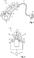
- Fig. 1 is a hearing instrument, referred to as "hearing aid 1" for short.
- the hearing aid 1 comprises a housing 2 in which several electrical components of the hearing aid 1 are arranged. These components are specifically formed by two microphones 3, a control unit 4 and a loudspeaker 6.
- the microphones 3 are used in the intended operation of the hearing aid 1 to generate audio input signals S A from ambient noise of the hearing aid 1. These are passed on to the control unit 4 and converted by the control unit 4 into audio output signals S L , which are output to the loudspeaker 6, by processing stored signal processing algorithms . From this, the audio output signals S L are output via a sound tube 8 and an ear mold 10 to the hearing of a user of the hearing aid 1.
- the hearing aid 1 has a rechargeable battery 12 for supplying energy to the electrical components.
- charging and converter electronics 14 are integrated into control unit 4.
- the hearing aid 1 In order to input control commands to the control unit 4, the hearing aid 1 has a push button 16 which is accessible from an outside of the housing 2. To connect the battery 12 to a charging energy source during an intended charging operation, the hearing aid 1 also has a connector 18. This connector 18 is set up and provided for the magnetic mounting of a connector counterpart 20 of a charging cable 22 (see Fig. Fig. 2 ). The connector 18 has a circular outer structure. The connector counterpart 20 of the charging cable 22 is designed to be complementary to the connector 18.
- the connector 18 has a first contact surface 24, which is formed in the shape of a circular ring, and a second contact surface 26 which is surrounded by the first contact surface 24 and is thus arranged concentrically therewith.
- the second contact surface 26 represents a head of the push button 16 accessible from the outside.
- the two contact surfaces 24 and 26 are electrically isolated from one another and serve to contact the two charging contacts of the battery 12, which are at different electrical potentials Fig. 1 only one connector 18 is provided.
- the hearing aid 1 has a connector 18 on each of the two “flat sides” 28.
- the push button 16 is integrated into one of the two connectors 18.
- each of the connectors 18 has only one contact surface which, in the intended charging operation, is assigned to one of two charging contacts which are at different electrical potentials.
- the charging cable 22 also has two connector counterparts 20.
- the hearing aid 1 and the charging cable 22 together form a hearing instrument system 30.
- the charging cable 22 also has a USB connector 32 at its end facing away from the respective connector counterpart 20.
Landscapes
- Physics & Mathematics (AREA)
- Engineering & Computer Science (AREA)
- Acoustics & Sound (AREA)
- Signal Processing (AREA)
- Health & Medical Sciences (AREA)
- General Health & Medical Sciences (AREA)
- Neurosurgery (AREA)
- Otolaryngology (AREA)
- Charge And Discharge Circuits For Batteries Or The Like (AREA)
- Battery Mounting, Suspending (AREA)
- Headphones And Earphones (AREA)
Abstract
Description
- Die Erfindung betrifft ein Hörinstrumentesystem, insbesondere ein Hörhilfegerätesystem.
- Hörinstrumente dienen üblicherweise zur Ausgabe eines Tonsignals an das Gehör des Trägers dieses Hörinstruments. Die Ausgabe erfolgt dabei mittels eines Ausgabewandlers, meist auf akustischem Weg über Luftschall mittels eines Lautsprechers (auch als "Hörer" oder "Receiver" bezeichnet). Häufig kommen derartige Hörinstrumente dabei als sogenannte Hörhilfegeräte (auch kurz: Hörgeräte) zum Einsatz. Dazu umfassen die Hörinstrumente normalerweise einen akustischen Eingangswandler (insbesondere ein Mikrofon) und einen Signalprozessor (auch als Steuereinheit bezeichnet), der dazu eingerichtet ist, das von dem Eingangswandler aus den erfassten Umgebungsgeräuschen erzeugte Eingangssignal (auch: Mikrofonsignal) unter Anwendung mindestens eines üblicherweise nutzerspezifisch hinterlegten und/oder angepassten Signalverarbeitungsalgorithmus derart zu verarbeiten, dass eine Hörminderung des Trägers des Hörinstruments zumindest teilweise kompensiert wird. Insbesondere im Fall eines Hörhilfegeräts kann es sich bei dem Ausgabewandler neben einem Lautsprecher alternativ auch um einen sogenannten Knochenleitungshörer oder ein Cochlea-Implantat handeln, die zur mechanischen bzw. elektrischen Einkopplung des Tonsignals in das Gehör des Trägers eingerichtet sind. Hörhilfegeräte kommen häufig in Form von zumindest teilweise hinter dem Ohr zu tragenden Hörhilfegeräten (kurz als "hdO" bezeichnet) sowie als ganz oder teilweise im Gehörgang zu tragenden Hörhilfegeräten (kurz als "idO" oder "in ear" bezeichnet) zum Einsatz. Unter den Begriff Hörinstrument fallen insbesondere auch Geräte wie z. B. sogenannte Tinnitus-Masker, Headsets, Kopfhörer und dergleichen.
- Zur Energieversorgung der elektronischen Komponenten des Hörinstruments-beispielsweise des Signalprozessors, des jeweiligen Mikrofons, des Lautsprechers und dergleichen - weisen herkömmliche Hörinstrumente häufig Batterien auf, die regelmäßig gewechselt werden müssen. Bei modernen Hörvorrichtungen kommen aber auch wiederaufladbare Batterien (auch als Akkumulatoren oder Akkus bezeichnet) zum Einsatz. Diese müssen jedoch - aufgrund ihrer meist vergleichsweise geringeren Energiedichte entsprechend häufiger - geladen werden. Üblicherweise werden diese wiederaufladbaren Batterien, konkret eine diesen zugeordnete Ladeelektronik zum Laden galvanisch mit einer Energiequelle verbunden. Zum Aufladen wird dabei beispielsweise das entsprechende Hörinstrument mit einem spezifischen Ladekabel verbunden. Häufig weisen derartige Ladekabel vergleichsweise aufwendig gestaltete Steckanschlüsse auf, beispielsweise Klinkenstecker oder miniaturisierte USB-Steckanschlüsse, die neben anderen funktionalen Elementen des Hörinstruments, beispielsweise Schalter oder Taster zur Lautstärkeregelung oder sonstigen Steuerung des Hörinstruments an diesem angeordnet werden müssen.
- Der Erfindung liegt die Aufgabe zugrunde, ein besonders einfaches Laden einer wiederaufladbaren Batterie zu ermöglichen.
- Diese Aufgabe wird erfindungsgemäß gelöst durch ein Hörinstrumentesystem mit den Merkmalen des Anspruchs 1. Weitere vorteilhafte und teils für sich erfinderische Ausführungsformen und Weiterentwicklungen der Erfindung sind in den Unteransprüchen und der nachfolgenden Beschreibung dargelegt.
- Das erfindungsgemäße Hörinstrumentesystem umfasst ein Hörinstrument, insbesondere ein Hörhilfegerät (auch kurz "Hörgerät"). Dieses Hörinstrument weist eine Steuereinheit auf, die wenigstens zur Verarbeitung von Audioeingangssignalen in Audioausgangssignale eingerichtet ist. Des Weiteren weist das Hörinstrument eine wiederaufladbare Batterie zur Energieversorgung der Steuereinheit auf. Außerdem weist das Hörinstrument ein Gehäuse auf, in dem die Batterie und die Steuereinheit angeordnet sind. Ferner weist das Hörinstrument einen Druckknopf auf, der zur Eingabe von Steuersignalen an die Steuereinheit dient und der vorzugsweise von einer Außenseite des Gehäuses zugänglich für einen Nutzer des Hörinstruments angeordnet ist. Außerdem weist das Hörinstrument wenigstens einen Konnektor auf, der zur elektrischen Verbindung der Batterie mit einer Ladeenergiequelle dient. Der Druckknopf zur (insbesondere nutzerseitigen) Eingabe von Steuersignalen (beispielsweise zum An- oder Abschalten des Hörinstruments) ist dabei in den Konnektor integriert. Der Konnektor ist außerdem zur magnetischen Halterung eines Konnektorgegenstücks eines Ladekabels magnetisiert.
- Bei der Steuereinheit handelt es sich um einen "Controller", der wenigstens zur Verarbeitung der Audioeingangssignale eingerichtet und vorgesehen ist. Optional ist dieser Controller auch zur Steuerung eines Ladevorgangs der wiederaufladbaren Batterie eingerichtet und vorgesehen. Vorzugsweise weist der Controller dabei wenigstens einen Mikrocontroller und einen zugeordneten Datenspeicher auf, in dem ein Programm zur Verarbeitung der Audioeingangssignale softwaretechnisch hinterlegt ist. Alternativ weist der Controller wenigstens einen anwendungsspezifischen Chip auf, auf dem das vorstehend beschriebene Programm mit schaltungstechnischen Mitteln implementiert ist.
- Unter einem Audioeingangs- und einem Audioausgangssignal wird hier und im Folgenden ein elektrisches Signal verstanden, das Geräusche im hörbaren Frequenzbereich widerspiegelt. Optional weist das Hörinstrument zur Generierung der Audioeingangssignale wenigstens ein Mikrofon und/oder einen entsprechenden Signalanschluss (zum Empfang der Audioeingangssignale, bspw. eine Antenne oder dergleichen) auf. Zur Wandlung der erzeugten Audioausgangssignale weist das Hörinstrument vorzugsweise einen Lautsprecher, alternativ aber auch Mittel zur mechanischen oder elektrischen Stimulation des Gehörs des Nutzers des Hörinstruments auf.
- Dadurch, dass der Druckknopf in den Konnektor integriert ist, kann vorteilhafterweise Bauraum an dem Hörinstrument eingespart werden und somit gegebenenfalls auch für andere Funktionen bereitgestellt oder für eine Miniaturisierung des Hörinstruments genutzt werden. Aufgrund der magnetischen Halterung des Konnektorgegenstücks können mechanische Haltemittel, insbesondere Rastmittel zur Verrastung des Konnektorgegenstücks an dem Konnektor oder dem Gehäuse des Hörinstruments, die häufig Verschleiß unterworfen sind, entfallen.
- In einer bevorzugten Ausführung weist der Konnektor eine kreisförmige Außenkontur auf. Der Druckknopf ist in diesem Fall insbesondere kreisringförmig von einer Kontaktfläche des Konnektors umgeben. Mithin ist der Druckknopf vorzugsweise konzentrisch zu der Kontaktfläche des Konnektors angeordnet. Dadurch ist auch eine besonders einfache Kontaktierung des Konnektors mittels des Konnektorgegenstücks möglich, da dieses aufgrund der kreisförmigen Außenkontur frei um 360 Grad verdreht an den Konnektor angesetzt werden kann. Eine Gefahr von Beschädigungen des Konnektors und/oder des Konnektorgegenstücks aufgrund einer beispielsweise rechteckförmigen oder trapezförmigen Geometrie ist somit verringert.
- In einer weiteren bevorzugten Ausführung weist das Hörinstrumentesystem auch das vorstehend genannte Ladekabel auf. Dessen Konnektorgegenstück ist dabei zur magnetischen Befestigung an dem Konnektor des für Instruments ebenfalls magnetisiert.
- Zur Magnetisierung des Konnektors und/oder des Konnektorgegenstücks weisen diese beispielsweise einen massiven Dauermagneten auf. Alternativ weisen vorzugsweise beide einen komplementär ausgeformten, spritzgegossenen und somit kunststoffgebundenen Dauermagneten auf.
- In einer zur Einsparung von Bauraum vorteilhaften Ausführung weist der Konnektor des Hörinstruments eine erste und eine zweite, zu der ersten Kontaktfläche gegenpolige zweite Kontaktfläche auf. Die zweite Kontaktfläche ist dabei vorzugsweise konzentrisch zu der ersten Kontaktfläche angeordnet und von dieser elektrisch isoliert. Unter dem Begriff "gegenpolig" wird hier und im Folgenden insbesondere verstanden, dass dieser zweiten Kontaktfläche im bestimmungsgemäßen Ladebetrieb des Hörinstruments ein anderes elektrisches Potential zugewiesen ist als der ersten Kontaktfläche. In diesem Fall sind mithin zur "vollständigen" Verbindung der wiederaufladbaren Batterie mit der Ladeenergiequelle nur ein Konnektor und somit auch nur ein Konnektorgegenstück erforderlich.
- Vorzugsweise ist das Konnektorgegenstück des Ladekabels komplementär zu dem Konnektor ausgebildet. Mithin weist das Konnektorgegenstück des Ladekabels zwei konzentrisch zueinander angeordnete Gegenkontakte für die beiden Kontaktflächen auf.
- In einer besonders zweckmäßigen Weiterbildung bildet die zweite Kontaktfläche des Konnektors einen von einem Nutzer des Hörinstruments betätigbaren, vorzugsweise beweglichen Teil des Druckknopfs. Beispielsweise bildet die zweite Kontaktfläche dabei den Kopf eines "Stößels" des Druckknopfs, der zur Auslösung des entsprechenden Steuersignals von dem Nutzer des Instruments bewegt, insbesondere eingedrückt werden muss.
- In einer alternativen Ausführung weist das Hörinstrument einen weiteren (zweiten) Konnektor auf. Beide Konnektoren weisen in diesem Fall jeweils (nur) eine Kontaktfläche auf. Außerdem sind beide Konnektoren wie vorstehend beschrieben zur magnetischen Halterung jeweils eines Konnektorgegenstücks des Ladekabels eingerichtet.
- In einer bevorzugten Weiterbildung ist in einem bestimmungsgemäßen Ladebetrieb an jedem der beiden Konnektoren mithin ein Konnektorgegenstück des Ladekabels angeschlossen und jeder der beiden Konnektoren dabei mit einem unterschiedlichen elektrischen Potential verbunden.
- Zweckmäßigerweise umfasst das vorstehend beschriebene Ladekabel auch die zwei Konnektorgegenstücke, die zur Verbindung mit den beiden Konnektoren des Hörinstruments eingerichtet und vorgesehen sind.
- In diesem Fall ist das Ladekabel vorzugsweise Y-förmig ausgebildet und weist dabei einen "Stammabschnitt" und zwei, von diesem Stammabschnitt ausgehende und die jeweiligen Konnektorgegenstücke endseitig tragende Zweigabschnitte auf. Zur Verbindung mit der Ladeenergiequelle weist das Ladekabel einen an dem Stammabschnitt angeordneten USB-Konnektor auf. Mithin handelt es sich bei dem Ladekabel um einen USB-Ladekabel, das beispielsweise zum Anschluss an einen Computer-USB-Port oder an einen entsprechenden Abwärtswandler, der zum Wandeln einer vom öffentlichen Stromnetz bereitgestellten Netzspannung auf eine Ladespannung für die wiederaufladbare Batterie eingerichtet und vorgesehen ist.
- Nachfolgend werden Ausführungsbeispiele der Erfindung anhand einer Zeichnung näher dargestellt. Darin zeigen:
-
Fig. 1 in einer schematischen Seitenansicht ein Hörinstrument mit einem teildurchsichtigen Gehäuse, und -
Fig. 2 in einer Draufsicht ein alternatives Ausführungsbeispiel des Hörinstruments. - Einander entsprechende Teile und Größen sind in allen Figuren stets mit gleichen Bezugszeichen versehen.
- In
Fig. 1 ist ein Hörinstrument, kurz als "Hörgerät 1" bezeichnet dargestellt. Das Hörgerät 1 umfasst ein Gehäuse 2, in dem mehrere elektrische Komponenten des Hörgeräts 1 angeordnet sind. Diese Komponenten sind konkret durch zwei Mikrofone 3, eine Steuereinheit 4 und einen Lautsprecher 6 gebildet. Die Mikrofone 3 dienen im bestimmungsgemäßen Betrieb des Hörgeräts 1 zur Erzeugung von Audioeingangssignalen SA aus Umgebungsgeräuschen des Hörgeräts 1. Diese werden an die Steuereinheit 4 weitergegeben und von dieser unter Abarbeitung von hinterlegten Signalverarbeitungsalgorithmen in Audioausgangssignale SL gewandelt, die an den Lautsprecher 6 ausgegeben werden. Von diesem werden die Audioausgangssignale SL über einen Schallschlauch 8 und ein Ohrpassstück 10 an das Gehör eines Nutzers des Hörgeräts 1 ausgegeben. Zur Energieversorgung der elektrischen Komponenten weist das Hörgerät 1 eine wiederaufladbare Batterie 12 auf. Im dargestellten Ausführungsbeispiel ist eine Lade- und Wandlerelektronik 14 in die Steuereinheit 4 integriert. - Zur Eingabe von Steuerbefehlen an die Steuereinheit 4 weist das Hörgerät 1 einen Druckknopf 16 auf, der von einer Außenseite des Gehäuses 2 zugänglich ist. Zur Verbindung der Batterie 12 mit einer Ladeenergiequelle während eines bestimmungsgemäßen Ladebetriebs weist das Hörgerät 1 außerdem einen Konnektor 18 auf. Dieser Konnektor 18 ist dabei zur magnetischen Halterung eines Konnektorgegenstücks 20 eines Ladekabels 22 eingerichtet und vorgesehen (s.
Fig. 2 ). Der Konnektor 18 weist dabei eine kreisförmige Außenstruktur auf. Das Konnektorgegenstück 20 des Ladekabels 22 ist dabei komplementär zu dem Konnektor 18 ausgebildet. - Im Ausführungsbeispiel gemäß
Fig. 1 weist der Konnektor 18 eine erste Kontaktfläche 24 auf die kreisringförmig ausgebildet ist, und eine zweite Kontaktfläche 26, die von der ersten Kontaktfläche 24 umgeben und somit konzentrisch zu dieser angeordnet ist. Die zweite Kontaktfläche 26 stellt dabei einen von der Außenseite her zugänglichen Kopf des Druckknopfs 16 dar. Die beiden Kontaktflächen 24 und 26 sind dabei elektrisch voneinander isoliert und dienen zur Kontaktierung der beiden auf unterschiedlichen elektrischen Potentialen liegenden Ladekontakte der Batterie 12. Somit ist im Ausführungsbeispiel gemäßFig. 1 nur ein Konnektor 18 vorgesehen. - Im Ausführungsbeispiel gemäß
Fig. 2 weist das Hörgerät 1 auf beiden "Flachseiten" 28 jeweils einen Konnektor 18 auf. In einen der beiden Konnektoren 18 ist dabei der Druckknopf 16 integriert. Jeder der Konnektoren 18 weist in diesem Ausführungsbeispiel jedoch nur eine Kontaktfläche auf, die im bestimmungsgemäßen Ladebetrieb einem von zwei auf unterschiedlichem elektrischen Potential liegenden Ladekontakten zugeordnet ist. In diesem Fall weist das Ladekabel 22 auch zwei Konnektorgegenstücke 20 auf. - In beiden Ausführungsbeispielen gemäß
Fig. 1 und Fig. 2 bilden das Hörgerät 1 und das Ladekabel 22 gemeinsam ein Hörinstrumentesystem 30. - Das Ladekabel 22 weist auch in beiden Ausführungsbeispielen an seinem, dem jeweiligen Konnektorgegenstück 20 abgewandten Ende einen USB-Konnektor 32 auf.
- Der Gegenstand der Erfindung ist nicht auf die vorstehend beschriebenen Ausführungsbeispiele beschränkt. Vielmehr können weitere Ausführungsformen der Erfindung von dem Fachmann aus der vorstehenden Beschreibung abgeleitet werden. Insbesondere können die anhand der verschiedenen Ausführungsbeispiele beschriebenen Einzelmerkmale der Erfindung und deren Ausgestaltungsvarianten auch in anderer Weise miteinander kombiniert werden.
-
- 1
- Hörgerät
- 2
- Gehäuse
- 3
- Mikrofon
- 4
- Steuereinheit
- 6
- Lautsprecher
- 8
- Schallschlauch
- 10
- Ohrpassstück
- 12
- Batterie
- 14
- Lade- und Wandlerelektronik
- 16
- Druckknopf
- 18
- Konnektor
- 20
- Konnektorgegenstück
- 22
- Ladekabel
- 24
- Kontaktfläche
- 26
- Kontaktfläche
- 28
- Flachseite
- 30
- Hörinstrumentesystem
- 32
- USB-Konnektor
- SA
- Audioeingangssignal
- SL
- Audioausgangssignal
Claims (10)
- Hörinstrumentesystem (30),
mit einem Hörinstrument (1) aufweisend- eine Steuereinheit (4), die wenigstens zur Verarbeitung von Audioeingangssignalen (SA) in Audioausgangssignale (SL) eingerichtet ist,- eine wiederaufladbare Batterie (12) zur Energieversorgung der Steuereinheit (4),- ein Gehäuse (2), in dem die Batterie (12) und die Steuereinheit (4) angeordnet sind,- einen Druckknopf (16) zur Eingabe von Steuersignalen an die Steuereinheit (4), und- wenigstens einen Konnektor (18) zur elektrischen Verbindung der Batterie (1) mit einer Ladeenergiequelle,
wobei der Druckknopf (16) in den Konnektor (18) integriert ist und wobei der Konnektor (18) zur magnetischen Halterung eines Konnektorgegenstücks (20) eines Ladekabels (22) magnetisiert ist. - Hörinstrumentesystem (30) nach Anspruch 1,
wobei der Konnektor (18) eine kreisförmige Außenkontur aufweist, und wobei der Druckknopf (16) kreisringförmig von einer Kontaktfläche (24) des Konnektors (18) umgeben ist. - Hörinstrumentesystem (30) nach Anspruch 1 oder 2,
aufweisend das Ladekabel (22), wobei dessen Konnektorgegenstück (20) zur magnetischen Befestigung an dem Konnektor (18) des Hörinstruments (1) magnetisiert ist. - Hörinstrumentesystem (30) nach einem der Ansprüche 1 bis 3,
wobei der Konnektor (18) eine erste und eine zweite, zu der ersten gegenpolige zweite Kontaktfläche (24,26) aufweist, wobei die zweite Kontaktfläche (26) konzentrisch zu der ersten Kontaktfläche (24) angeordnet und von dieser elektrisch isoliert ist. - Hörinstrumentesystem (30) nach Anspruch 4,
wobei das Konnektorgegenstück (20) des Ladekabels (22) zwei konzentrisch angeordnete Gegenkontakte aufweist. - Hörinstrumentesystem (30) nach Anspruch 4 oder 5,
wobei die zweite Kontaktfläche (26) einen von einem Nutzer des Hörinstruments betätigbaren Teil des Druckknopfs (16) bildet. - Hörinstrumentesystem (30) nach einem der Ansprüche 1 bis 3,
wobei das Hörinstrument (1) einen weiteren Konnektor (18) aufweist, wobei beide Konnektoren (18) jeweils eine Kontaktfläche aufweisen, und wobei beide Konnektoren (18) zur magnetischen Halterung jeweils eines Konnektorgegenstücks (20) des Ladekabels (22) eingerichtet sind. - Hörinstrumentesystem (30) nach Anspruch 7,
wobei in einem bestimmungsgemäßen Ladebetrieb an jedem der beiden Konnektoren (18) ein Konnektorgegenstück (20) des Ladekabels (22) angeschlossen ist und jeder der beiden Konnektoren (18) mit einem unterschiedlichen elektrischen Potential verbunden ist. - Hörinstrumentesystem (30) nach den Ansprüchen 3 und 7 oder 8,
wobei das Ladekabel (22) die zwei Konnektorgegenstücke (20) zur Verbindung mit den beiden Konnektoren (18) des Hörinstruments (1) umfasst. - Hörinstrumentesystem (30) nach Anspruch 9,
wobei das Ladekabel (22) Y-förmig mit einem Stammabschnitt und zwei, die Konnektorgegenstücke (20) endseitig tragenden Zweigabschnitten ausgebildet ist und zur Verbindung mit der Ladeenergiequelle an dem Stammabschnitt einen USB-Konnektor (32) aufweist.
Applications Claiming Priority (1)
| Application Number | Priority Date | Filing Date | Title |
|---|---|---|---|
| DE102019201784.3A DE102019201784B3 (de) | 2019-02-12 | 2019-02-12 | Hörinstrumentesystem |
Publications (2)
| Publication Number | Publication Date |
|---|---|
| EP3697103A1 true EP3697103A1 (de) | 2020-08-19 |
| EP3697103B1 EP3697103B1 (de) | 2022-08-10 |
Family
ID=69147519
Family Applications (1)
| Application Number | Title | Priority Date | Filing Date |
|---|---|---|---|
| EP20150664.9A Active EP3697103B1 (de) | 2019-02-12 | 2020-01-08 | Hörinstrumentesystem mit platzsparendem batterieladeanschluss |
Country Status (5)
| Country | Link |
|---|---|
| EP (1) | EP3697103B1 (de) |
| JP (1) | JP6919004B2 (de) |
| CN (1) | CN111556421B (de) |
| DE (1) | DE102019201784B3 (de) |
| DK (1) | DK3697103T3 (de) |
Citations (3)
| Publication number | Priority date | Publication date | Assignee | Title |
|---|---|---|---|---|
| US20090067652A1 (en) * | 2007-09-06 | 2009-03-12 | Siemens Medical Instruments Pte., Ltd. | Hearing device with a contact unit and an associated external unit |
| US20110026747A1 (en) * | 2008-03-28 | 2011-02-03 | Phonak Ag | Hearing device with user control |
| US20170195771A1 (en) * | 2016-01-02 | 2017-07-06 | Erato (Cayman) Holdings Co., Ltd. | Wireless earphone and controlling method of same |
Family Cites Families (21)
| Publication number | Priority date | Publication date | Assignee | Title |
|---|---|---|---|---|
| JPH0523699U (ja) * | 1991-09-05 | 1993-03-26 | テルモ株式会社 | 補聴器 |
| US6636749B2 (en) * | 2001-06-25 | 2003-10-21 | At&T Wireless Services, Inc. | Method and apparatus for providing power and wireless protocol capability to a wireless device, such as a wireless phone |
| JP4096693B2 (ja) * | 2002-10-17 | 2008-06-04 | 松下電器産業株式会社 | 再生装置 |
| US20100142740A1 (en) * | 2007-04-16 | 2010-06-10 | Gn Resound A/S | Hearing aid wireless communication adaptor |
| DE102008022925A1 (de) | 2008-05-09 | 2009-06-04 | Siemens Medical Instruments Pte. Ltd. | Wiederaufladbare Hörhilfe und Ladevorrichtung |
| DE102008038649A1 (de) | 2008-08-12 | 2010-02-18 | Rosenberger Hochfrequenztechnik Gmbh & Co. Kg | Vorrichtung zur Herstellung einer Verbindung |
| US9627903B2 (en) * | 2009-07-24 | 2017-04-18 | Robert M. Schwartz | Current sensing circuit disconnect device and method |
| CN201479365U (zh) * | 2009-09-11 | 2010-05-19 | 韦景新 | 双喇叭耳聋机 |
| CN202153756U (zh) * | 2011-07-06 | 2012-02-29 | 深圳市沃特沃德科技有限公司 | 一种直板型移动终端的主板 |
| EP3025512A1 (de) * | 2013-07-22 | 2016-06-01 | Sonova AG | Wiederaufladbares hörgerät und batterieladevorrichtung zum laden des hörgeräts |
| CN105556988B (zh) | 2013-09-18 | 2019-03-22 | 领先仿生公司 | 助听装置和与其一起使用的用户界面 |
| US9614378B2 (en) * | 2013-09-30 | 2017-04-04 | Apple Inc. | Inductive charging interface with magnetic retention for electronic devices and accessories |
| DE102014015148B4 (de) * | 2014-10-13 | 2018-11-29 | Sumitomo Wiring Systems, Ltd. | Ladeverbinder und Verfahren zum Montieren desselben |
| US9407981B2 (en) * | 2014-10-17 | 2016-08-02 | Apple Inc. | Audio class-compliant charging accessories for wireless headphones and headsets |
| DE102015203536B4 (de) | 2015-02-27 | 2019-08-29 | Sivantos Pte. Ltd. | Mobiler kontaktloser Ladeadapter |
| US20170255029A1 (en) | 2016-03-03 | 2017-09-07 | Vision Service Plan | Systems and methods for charging eyewear |
| US20170264991A1 (en) | 2016-03-11 | 2017-09-14 | Voxx International Corporation | Headphone or earphone assembly having a pivotable usb charging connector integrated into a housing thereof |
| DK3297292T3 (da) * | 2016-09-19 | 2020-04-14 | Sennheiser Communications As | Ørekop med fastgørelsesenhed |
| DE102017207643A1 (de) * | 2017-05-05 | 2018-11-08 | Sivantos Pte. Ltd. | Hörgerät |
| CN207010975U (zh) * | 2017-08-01 | 2018-02-13 | 厦门新声科技有限公司 | 一种助听器 |
| CN208063273U (zh) * | 2018-04-09 | 2018-11-06 | 罗立军 | 一种用于车载手机支架与磁吸充电线连接的连接件 |
-
2019
- 2019-02-12 DE DE102019201784.3A patent/DE102019201784B3/de not_active Expired - Fee Related
-
2020
- 2020-01-08 EP EP20150664.9A patent/EP3697103B1/de active Active
- 2020-01-08 DK DK20150664.9T patent/DK3697103T3/da active
- 2020-02-12 CN CN202010088095.2A patent/CN111556421B/zh active Active
- 2020-02-12 JP JP2020021095A patent/JP6919004B2/ja not_active Expired - Fee Related
Patent Citations (3)
| Publication number | Priority date | Publication date | Assignee | Title |
|---|---|---|---|---|
| US20090067652A1 (en) * | 2007-09-06 | 2009-03-12 | Siemens Medical Instruments Pte., Ltd. | Hearing device with a contact unit and an associated external unit |
| US20110026747A1 (en) * | 2008-03-28 | 2011-02-03 | Phonak Ag | Hearing device with user control |
| US20170195771A1 (en) * | 2016-01-02 | 2017-07-06 | Erato (Cayman) Holdings Co., Ltd. | Wireless earphone and controlling method of same |
Also Published As
| Publication number | Publication date |
|---|---|
| CN111556421A (zh) | 2020-08-18 |
| DK3697103T3 (da) | 2022-11-14 |
| JP2020137120A (ja) | 2020-08-31 |
| EP3697103B1 (de) | 2022-08-10 |
| JP6919004B2 (ja) | 2021-08-11 |
| DE102019201784B3 (de) | 2020-06-10 |
| CN111556421B (zh) | 2021-11-02 |
Similar Documents
| Publication | Publication Date | Title |
|---|---|---|
| EP0591791B1 (de) | Programmierbares Hörhilfegerät | |
| EP1962557B1 (de) | Hörvorrichtung mit einem speziellen Energieaufnahmesystem und entsprechendes Verfahren | |
| CH673551A5 (en) | Hearing aid with direct audio input connection - provided by audio plug fitted into battery compartment upon battery removal | |
| EP2285136A1 (de) | Hörhilfe mit wechselbarem Hörer | |
| WO2019105949A1 (de) | Modulares hörgerät | |
| DE102010040930B4 (de) | Hörgerät mit einer Batterielade | |
| CH669296A5 (en) | Electroacoustic hearing aid with contact for external equipment - has battery compartment adapted to accept plug connection from external broadcast receiver or voice communication appts. | |
| DE102008024515B3 (de) | Hörhilfe und Anordnung | |
| EP3697103B1 (de) | Hörinstrumentesystem mit platzsparendem batterieladeanschluss | |
| DE102008020926A1 (de) | Drucktaster für ein Hörgerät | |
| DE102008008670A1 (de) | Ladegerät für eine Hörvorrichtung mit einem bewegbaren Ladekontakt | |
| DE102010009702A1 (de) | Hörvorrichtung mit einem Leitelement, insbesondere einem Schallschlauch | |
| EP3905723A1 (de) | Hörvorrichtung | |
| DE102007054603B4 (de) | Hörvorrichtung mit gesteuerter Programmierbuchse | |
| EP2091271A2 (de) | In-dem-Ohr-Hörgerät mit bewegbarem Griffelement | |
| WO2023052436A1 (de) | Magnetischer steckverbinder für einen galvanischen ladeanschluss eines elektronischen geräts, insbesondere eines hörinstruments | |
| DE102021205471B3 (de) | Hörvorrichtung | |
| WO2009040205A2 (de) | Hörgerät mit teilen aus elektrisch leitfähigem und gleichzeitig schalldämmendem material | |
| CH668154A5 (en) | Hearing aid with electroacoustic transducer - fits behind ear and has facility for plugging in range of operational mode elements | |
| EP4195703A1 (de) | Ladekontaktanordnung, hörvorrichtung und hörvorrichtungssystem | |
| DE19749110A1 (de) | Programmierbares Hörhilfegerät | |
| DE102013210170B4 (de) | Modulare Hörgerätegehäusevorrichtung für Hörgeräte | |
| EP2018078A2 (de) | Hörvorrichtung mit einer Befestigungseinrichtung zum Anstecken eines Audioschuhs und entsprechender Audioschuh | |
| DE102009008456B4 (de) | Automatische Hörerkennung bei Hörhilfegeräten | |
| DE102010041838A1 (de) | Hörgerät mit einem wiederaufladbaren Energiespeichermittel |
Legal Events
| Date | Code | Title | Description |
|---|---|---|---|
| PUAI | Public reference made under article 153(3) epc to a published international application that has entered the european phase |
Free format text: ORIGINAL CODE: 0009012 |
|
| STAA | Information on the status of an ep patent application or granted ep patent |
Free format text: STATUS: THE APPLICATION HAS BEEN PUBLISHED |
|
| AK | Designated contracting states |
Kind code of ref document: A1 Designated state(s): AL AT BE BG CH CY CZ DE DK EE ES FI FR GB GR HR HU IE IS IT LI LT LU LV MC MK MT NL NO PL PT RO RS SE SI SK SM TR |
|
| AX | Request for extension of the european patent |
Extension state: BA ME |
|
| STAA | Information on the status of an ep patent application or granted ep patent |
Free format text: STATUS: REQUEST FOR EXAMINATION WAS MADE |
|
| 17P | Request for examination filed |
Effective date: 20210211 |
|
| RBV | Designated contracting states (corrected) |
Designated state(s): AL AT BE BG CH CY CZ DE DK EE ES FI FR GB GR HR HU IE IS IT LI LT LU LV MC MK MT NL NO PL PT RO RS SE SI SK SM TR |
|
| GRAP | Despatch of communication of intention to grant a patent |
Free format text: ORIGINAL CODE: EPIDOSNIGR1 |
|
| STAA | Information on the status of an ep patent application or granted ep patent |
Free format text: STATUS: GRANT OF PATENT IS INTENDED |
|
| INTG | Intention to grant announced |
Effective date: 20220317 |
|
| GRAS | Grant fee paid |
Free format text: ORIGINAL CODE: EPIDOSNIGR3 |
|
| GRAA | (expected) grant |
Free format text: ORIGINAL CODE: 0009210 |
|
| STAA | Information on the status of an ep patent application or granted ep patent |
Free format text: STATUS: THE PATENT HAS BEEN GRANTED |
|
| AK | Designated contracting states |
Kind code of ref document: B1 Designated state(s): AL AT BE BG CH CY CZ DE DK EE ES FI FR GB GR HR HU IE IS IT LI LT LU LV MC MK MT NL NO PL PT RO RS SE SI SK SM TR |
|
| REG | Reference to a national code |
Ref country code: AT Ref legal event code: REF Ref document number: 1511448 Country of ref document: AT Kind code of ref document: T Effective date: 20220815 Ref country code: CH Ref legal event code: EP |
|
| REG | Reference to a national code |
Ref country code: DE Ref legal event code: R096 Ref document number: 502020001472 Country of ref document: DE |
|
| REG | Reference to a national code |
Ref country code: IE Ref legal event code: FG4D Free format text: LANGUAGE OF EP DOCUMENT: GERMAN |
|
| REG | Reference to a national code |
Ref country code: DK Ref legal event code: T3 Effective date: 20221107 |
|
| REG | Reference to a national code |
Ref country code: NL Ref legal event code: MP Effective date: 20220810 |
|
| REG | Reference to a national code |
Ref country code: LT Ref legal event code: MG9D |
|
| PG25 | Lapsed in a contracting state [announced via postgrant information from national office to epo] |
Ref country code: SE Free format text: LAPSE BECAUSE OF FAILURE TO SUBMIT A TRANSLATION OF THE DESCRIPTION OR TO PAY THE FEE WITHIN THE PRESCRIBED TIME-LIMIT Effective date: 20220810 Ref country code: RS Free format text: LAPSE BECAUSE OF FAILURE TO SUBMIT A TRANSLATION OF THE DESCRIPTION OR TO PAY THE FEE WITHIN THE PRESCRIBED TIME-LIMIT Effective date: 20220810 Ref country code: PT Free format text: LAPSE BECAUSE OF FAILURE TO SUBMIT A TRANSLATION OF THE DESCRIPTION OR TO PAY THE FEE WITHIN THE PRESCRIBED TIME-LIMIT Effective date: 20221212 Ref country code: NO Free format text: LAPSE BECAUSE OF FAILURE TO SUBMIT A TRANSLATION OF THE DESCRIPTION OR TO PAY THE FEE WITHIN THE PRESCRIBED TIME-LIMIT Effective date: 20221110 Ref country code: NL Free format text: LAPSE BECAUSE OF FAILURE TO SUBMIT A TRANSLATION OF THE DESCRIPTION OR TO PAY THE FEE WITHIN THE PRESCRIBED TIME-LIMIT Effective date: 20220810 Ref country code: LV Free format text: LAPSE BECAUSE OF FAILURE TO SUBMIT A TRANSLATION OF THE DESCRIPTION OR TO PAY THE FEE WITHIN THE PRESCRIBED TIME-LIMIT Effective date: 20220810 Ref country code: LT Free format text: LAPSE BECAUSE OF FAILURE TO SUBMIT A TRANSLATION OF THE DESCRIPTION OR TO PAY THE FEE WITHIN THE PRESCRIBED TIME-LIMIT Effective date: 20220810 Ref country code: FI Free format text: LAPSE BECAUSE OF FAILURE TO SUBMIT A TRANSLATION OF THE DESCRIPTION OR TO PAY THE FEE WITHIN THE PRESCRIBED TIME-LIMIT Effective date: 20220810 |
|
| PG25 | Lapsed in a contracting state [announced via postgrant information from national office to epo] |
Ref country code: PL Free format text: LAPSE BECAUSE OF FAILURE TO SUBMIT A TRANSLATION OF THE DESCRIPTION OR TO PAY THE FEE WITHIN THE PRESCRIBED TIME-LIMIT Effective date: 20220810 Ref country code: IS Free format text: LAPSE BECAUSE OF FAILURE TO SUBMIT A TRANSLATION OF THE DESCRIPTION OR TO PAY THE FEE WITHIN THE PRESCRIBED TIME-LIMIT Effective date: 20221210 Ref country code: HR Free format text: LAPSE BECAUSE OF FAILURE TO SUBMIT A TRANSLATION OF THE DESCRIPTION OR TO PAY THE FEE WITHIN THE PRESCRIBED TIME-LIMIT Effective date: 20220810 Ref country code: GR Free format text: LAPSE BECAUSE OF FAILURE TO SUBMIT A TRANSLATION OF THE DESCRIPTION OR TO PAY THE FEE WITHIN THE PRESCRIBED TIME-LIMIT Effective date: 20221111 |
|
| PG25 | Lapsed in a contracting state [announced via postgrant information from national office to epo] |
Ref country code: SM Free format text: LAPSE BECAUSE OF FAILURE TO SUBMIT A TRANSLATION OF THE DESCRIPTION OR TO PAY THE FEE WITHIN THE PRESCRIBED TIME-LIMIT Effective date: 20220810 Ref country code: RO Free format text: LAPSE BECAUSE OF FAILURE TO SUBMIT A TRANSLATION OF THE DESCRIPTION OR TO PAY THE FEE WITHIN THE PRESCRIBED TIME-LIMIT Effective date: 20220810 Ref country code: ES Free format text: LAPSE BECAUSE OF FAILURE TO SUBMIT A TRANSLATION OF THE DESCRIPTION OR TO PAY THE FEE WITHIN THE PRESCRIBED TIME-LIMIT Effective date: 20220810 Ref country code: CZ Free format text: LAPSE BECAUSE OF FAILURE TO SUBMIT A TRANSLATION OF THE DESCRIPTION OR TO PAY THE FEE WITHIN THE PRESCRIBED TIME-LIMIT Effective date: 20220810 |
|
| REG | Reference to a national code |
Ref country code: DE Ref legal event code: R097 Ref document number: 502020001472 Country of ref document: DE |
|
| PG25 | Lapsed in a contracting state [announced via postgrant information from national office to epo] |
Ref country code: SK Free format text: LAPSE BECAUSE OF FAILURE TO SUBMIT A TRANSLATION OF THE DESCRIPTION OR TO PAY THE FEE WITHIN THE PRESCRIBED TIME-LIMIT Effective date: 20220810 Ref country code: EE Free format text: LAPSE BECAUSE OF FAILURE TO SUBMIT A TRANSLATION OF THE DESCRIPTION OR TO PAY THE FEE WITHIN THE PRESCRIBED TIME-LIMIT Effective date: 20220810 |
|
| PLBE | No opposition filed within time limit |
Free format text: ORIGINAL CODE: 0009261 |
|
| STAA | Information on the status of an ep patent application or granted ep patent |
Free format text: STATUS: NO OPPOSITION FILED WITHIN TIME LIMIT |
|
| PG25 | Lapsed in a contracting state [announced via postgrant information from national office to epo] |
Ref country code: AL Free format text: LAPSE BECAUSE OF FAILURE TO SUBMIT A TRANSLATION OF THE DESCRIPTION OR TO PAY THE FEE WITHIN THE PRESCRIBED TIME-LIMIT Effective date: 20220810 |
|
| 26N | No opposition filed |
Effective date: 20230511 |
|
| PG25 | Lapsed in a contracting state [announced via postgrant information from national office to epo] |
Ref country code: SI Free format text: LAPSE BECAUSE OF FAILURE TO SUBMIT A TRANSLATION OF THE DESCRIPTION OR TO PAY THE FEE WITHIN THE PRESCRIBED TIME-LIMIT Effective date: 20220810 |
|
| PG25 | Lapsed in a contracting state [announced via postgrant information from national office to epo] |
Ref country code: LU Free format text: LAPSE BECAUSE OF NON-PAYMENT OF DUE FEES Effective date: 20230108 |
|
| REG | Reference to a national code |
Ref country code: BE Ref legal event code: MM Effective date: 20230131 |
|
| PG25 | Lapsed in a contracting state [announced via postgrant information from national office to epo] |
Ref country code: BE Free format text: LAPSE BECAUSE OF NON-PAYMENT OF DUE FEES Effective date: 20230131 |
|
| PG25 | Lapsed in a contracting state [announced via postgrant information from national office to epo] |
Ref country code: IE Free format text: LAPSE BECAUSE OF NON-PAYMENT OF DUE FEES Effective date: 20230108 |
|
| PG25 | Lapsed in a contracting state [announced via postgrant information from national office to epo] |
Ref country code: IT Free format text: LAPSE BECAUSE OF FAILURE TO SUBMIT A TRANSLATION OF THE DESCRIPTION OR TO PAY THE FEE WITHIN THE PRESCRIBED TIME-LIMIT Effective date: 20220810 |
|
| PG25 | Lapsed in a contracting state [announced via postgrant information from national office to epo] |
Ref country code: MC Free format text: LAPSE BECAUSE OF FAILURE TO SUBMIT A TRANSLATION OF THE DESCRIPTION OR TO PAY THE FEE WITHIN THE PRESCRIBED TIME-LIMIT Effective date: 20220810 |
|
| PG25 | Lapsed in a contracting state [announced via postgrant information from national office to epo] |
Ref country code: MC Free format text: LAPSE BECAUSE OF FAILURE TO SUBMIT A TRANSLATION OF THE DESCRIPTION OR TO PAY THE FEE WITHIN THE PRESCRIBED TIME-LIMIT Effective date: 20220810 |
|
| PG25 | Lapsed in a contracting state [announced via postgrant information from national office to epo] |
Ref country code: BG Free format text: LAPSE BECAUSE OF FAILURE TO SUBMIT A TRANSLATION OF THE DESCRIPTION OR TO PAY THE FEE WITHIN THE PRESCRIBED TIME-LIMIT Effective date: 20220810 |
|
| PG25 | Lapsed in a contracting state [announced via postgrant information from national office to epo] |
Ref country code: BG Free format text: LAPSE BECAUSE OF FAILURE TO SUBMIT A TRANSLATION OF THE DESCRIPTION OR TO PAY THE FEE WITHIN THE PRESCRIBED TIME-LIMIT Effective date: 20220810 |
|
| PGFP | Annual fee paid to national office [announced via postgrant information from national office to epo] |
Ref country code: AT Payment date: 20250417 Year of fee payment: 5 |
|
| PG25 | Lapsed in a contracting state [announced via postgrant information from national office to epo] |
Ref country code: CY Free format text: LAPSE BECAUSE OF FAILURE TO SUBMIT A TRANSLATION OF THE DESCRIPTION OR TO PAY THE FEE WITHIN THE PRESCRIBED TIME-LIMIT; INVALID AB INITIO Effective date: 20200108 |
|
| PG25 | Lapsed in a contracting state [announced via postgrant information from national office to epo] |
Ref country code: HU Free format text: LAPSE BECAUSE OF FAILURE TO SUBMIT A TRANSLATION OF THE DESCRIPTION OR TO PAY THE FEE WITHIN THE PRESCRIBED TIME-LIMIT; INVALID AB INITIO Effective date: 20200108 |
|
| PG25 | Lapsed in a contracting state [announced via postgrant information from national office to epo] |
Ref country code: TR Free format text: LAPSE BECAUSE OF FAILURE TO SUBMIT A TRANSLATION OF THE DESCRIPTION OR TO PAY THE FEE WITHIN THE PRESCRIBED TIME-LIMIT Effective date: 20220810 |
|
| PGFP | Annual fee paid to national office [announced via postgrant information from national office to epo] |
Ref country code: GB Payment date: 20251220 Year of fee payment: 7 |
|
| PGFP | Annual fee paid to national office [announced via postgrant information from national office to epo] |
Ref country code: DK Payment date: 20251217 Year of fee payment: 7 |
|
| PGFP | Annual fee paid to national office [announced via postgrant information from national office to epo] |
Ref country code: FR Payment date: 20251217 Year of fee payment: 7 |
|
| REG | Reference to a national code |
Ref country code: CH Ref legal event code: U11 Free format text: ST27 STATUS EVENT CODE: U-0-0-U10-U11 (AS PROVIDED BY THE NATIONAL OFFICE) Effective date: 20260201 |
|
| REG | Reference to a national code |
Ref country code: AT Ref legal event code: MM01 Ref document number: 1511448 Country of ref document: AT Kind code of ref document: T Effective date: 20250108 |
|
| PGFP | Annual fee paid to national office [announced via postgrant information from national office to epo] |
Ref country code: DE Payment date: 20251217 Year of fee payment: 7 |
|
| PG25 | Lapsed in a contracting state [announced via postgrant information from national office to epo] |
Ref country code: AT Free format text: LAPSE BECAUSE OF NON-PAYMENT OF DUE FEES Effective date: 20250108 |
|
| PGFP | Annual fee paid to national office [announced via postgrant information from national office to epo] |
Ref country code: CH Payment date: 20260201 Year of fee payment: 7 |