EP3696372B1 - Dispositif de forage du sol et utilisation d'un dispositif de forage du sol - Google Patents
Dispositif de forage du sol et utilisation d'un dispositif de forage du sol Download PDFInfo
- Publication number
- EP3696372B1 EP3696372B1 EP20156844.1A EP20156844A EP3696372B1 EP 3696372 B1 EP3696372 B1 EP 3696372B1 EP 20156844 A EP20156844 A EP 20156844A EP 3696372 B1 EP3696372 B1 EP 3696372B1
- Authority
- EP
- European Patent Office
- Prior art keywords
- rod
- magazine
- drill
- drilling
- transfer device
- Prior art date
- Legal status (The legal status is an assumption and is not a legal conclusion. Google has not performed a legal analysis and makes no representation as to the accuracy of the status listed.)
- Active
Links
- 238000005553 drilling Methods 0.000 claims description 36
- 238000000926 separation method Methods 0.000 claims description 4
- 239000000463 material Substances 0.000 description 6
- 230000006641 stabilisation Effects 0.000 description 4
- 238000011105 stabilization Methods 0.000 description 4
- 238000010276 construction Methods 0.000 description 2
- 230000005540 biological transmission Effects 0.000 description 1
- 230000001419 dependent effect Effects 0.000 description 1
- 239000004576 sand Substances 0.000 description 1
- 239000002689 soil Substances 0.000 description 1
- 239000004575 stone Substances 0.000 description 1
- 239000000725 suspension Substances 0.000 description 1
Images

Classifications
-
- E—FIXED CONSTRUCTIONS
- E21—EARTH OR ROCK DRILLING; MINING
- E21B—EARTH OR ROCK DRILLING; OBTAINING OIL, GAS, WATER, SOLUBLE OR MELTABLE MATERIALS OR A SLURRY OF MINERALS FROM WELLS
- E21B19/00—Handling rods, casings, tubes or the like outside the borehole, e.g. in the derrick; Apparatus for feeding the rods or cables
- E21B19/20—Combined feeding from rack and connecting, e.g. automatically
-
- E—FIXED CONSTRUCTIONS
- E21—EARTH OR ROCK DRILLING; MINING
- E21B—EARTH OR ROCK DRILLING; OBTAINING OIL, GAS, WATER, SOLUBLE OR MELTABLE MATERIALS OR A SLURRY OF MINERALS FROM WELLS
- E21B19/00—Handling rods, casings, tubes or the like outside the borehole, e.g. in the derrick; Apparatus for feeding the rods or cables
- E21B19/14—Racks, ramps, troughs or bins, for holding the lengths of rod singly or connected; Handling between storage place and borehole
- E21B19/15—Racking of rods in horizontal position; Handling between horizontal and vertical position
-
- E—FIXED CONSTRUCTIONS
- E21—EARTH OR ROCK DRILLING; MINING
- E21B—EARTH OR ROCK DRILLING; OBTAINING OIL, GAS, WATER, SOLUBLE OR MELTABLE MATERIALS OR A SLURRY OF MINERALS FROM WELLS
- E21B19/00—Handling rods, casings, tubes or the like outside the borehole, e.g. in the derrick; Apparatus for feeding the rods or cables
- E21B19/18—Connecting or disconnecting drill bit and drilling pipe
-
- E—FIXED CONSTRUCTIONS
- E21—EARTH OR ROCK DRILLING; MINING
- E21B—EARTH OR ROCK DRILLING; OBTAINING OIL, GAS, WATER, SOLUBLE OR MELTABLE MATERIALS OR A SLURRY OF MINERALS FROM WELLS
- E21B19/00—Handling rods, casings, tubes or the like outside the borehole, e.g. in the derrick; Apparatus for feeding the rods or cables
- E21B19/24—Guiding or centralising devices for drilling rods or pipes
-
- E—FIXED CONSTRUCTIONS
- E21—EARTH OR ROCK DRILLING; MINING
- E21B—EARTH OR ROCK DRILLING; OBTAINING OIL, GAS, WATER, SOLUBLE OR MELTABLE MATERIALS OR A SLURRY OF MINERALS FROM WELLS
- E21B7/00—Special methods or apparatus for drilling
- E21B7/02—Drilling rigs characterised by means for land transport with their own drive, e.g. skid mounting or wheel mounting
- E21B7/025—Rock drills, i.e. jumbo drills
-
- E—FIXED CONSTRUCTIONS
- E21—EARTH OR ROCK DRILLING; MINING
- E21B—EARTH OR ROCK DRILLING; OBTAINING OIL, GAS, WATER, SOLUBLE OR MELTABLE MATERIALS OR A SLURRY OF MINERALS FROM WELLS
- E21B7/00—Special methods or apparatus for drilling
- E21B7/04—Directional drilling
- E21B7/046—Directional drilling horizontal drilling
Definitions
- the invention relates to an earth drilling device and a use of an earth drilling device.
- a drilling device which has a rod magazine with a large number of rod sections stored therein, a drill carriage and a transfer device with which the rod sections can be removed from the rod magazine and positioned in the drill carriage.
- the rod magazine is positioned next to a base support of the drill carriage.
- the rod magazine has the shape of a cuboid and is made up of a plurality of frame profiles connected to one another.
- the top of the rod magazine is designed to be open, so that the transfer device reaches into the rod magazine and can remove a rod section.
- the transfer device is connected via a carrier frame both to an outer wall of the rod magazine and to the base carrier of the drill carriage. Horizontally aligned toothed racks are present on the support frame, which mesh with drive gears of a drive. A gripping unit of the transfer device can be moved in the horizontal direction along the horizontal toothed racks.
- DE 20 2011 110 844 U1 discloses a drilling device for laying pipelines underground.
- Rod sections are stored in a cage-like magazine that is open at the top and handled by means of a manipulator.
- the magazine for the rod sections is exchangeable in the manipulator.
- the manipulator consists of a base frame and a vertical frame.
- the rollers are guided in cross rails of a caterpillar vehicle with the drilling device.
- a lifting carriage is guided in the vertical frame Horizontal carriage accommodates as a carrier for an axially movable rod gripper, which is designed on the front side with a gripper.
- the gripping tongs are used to pick up the rod sections one after the other and place them in the drilling device in order to connect them there to the rear end of a pipe string that is to be laid in the ground and consists of individual rod sections.
- a support structure in addition to the rod magazine is disclosed.
- CN 104 165 031 B discloses an earth boring device including a guide for a transfer device, the guide including a support structure provided in addition to the rod magazine.
- the invention is now based on the object of providing a rod magazine on an earth drilling device and a transfer device for the transfer of a rod section in a simple manner, in which a simple structure and/or a simple construction is possible.
- the core idea of the invention is that there is a guide for moving the transfer device on the rod magazine itself. As a result, the use of material and/or the structural design can be reduced.
- the inventors have broken with the idea that a support structure for the transfer device must be provided independently of the rod magazine. So far, the design of the transfer device was associated with the idea that a superstructure must be created over the rod magazine in order to access the rod magazine or the rod sections located in the rod magazine. The considerations were based on maximum stabilization of the suspension or the arrangement of the transfer device, whereby, due to the weight of the rod sections, maximum stability of the rod magazine was only considered achievable if the rod magazine and transfer device were designed independently of one another.
- the invention provides an earth drilling device with a drill carriage which defines a drill string axis.
- the earth boring device also has a rod magazine for a plurality of rod sections and a transfer device for the transfer of a rod section between the rod magazine and a position of the rod section in the direction of the drill rod axis.
- a guide for moving the transfer device is provided on the rod magazine.
- the rod magazine has two head pieces running transversely to the longitudinal direction of the carriage, on each of which at least one guide for the transfer device is arranged.
- earth drilling device includes any device which, in particular, moves a drill rod containing rod sections in an existing or to be created channel in the ground in order to create or widen a bore, in particular a horizontal bore (HD), or pipelines or other long ones to sink bodies into the ground.
- the earth drilling device can in particular be an HD device.
- An earth drilling device can be a device that drives a drill rod, which can in particular work in a soil-displacing manner, and inserts the drill rod in a translatory and/or rotary manner in the longitudinal axial direction of the drill rod into the ground.
- a hole can be drilled into the ground by applying tension or pressure to the drill pipe.
- soil in the sense of the present description includes in particular any type of material, in particular earth, sand and/or stone, in which existing or to be created, preferably at least partially horizontal, channels or bores can be introduced.
- the term "drilling rig” includes a particularly mobile frame on which a carriage for moving the drill string can be provided, which can be moved back and forth in the direction of the drill string axis in order to push or pull the drill string in the ground.
- the drill rig usually includes at least the carriage and/or a linear drive for advancing the drill rod.
- the linear drive can additionally or alternatively have a rotary drive for rotating the drill rod.
- the drill carriage can also have one or more clamping devices, via which the drill rod or a rod section to be attached can be fixed. It can be provided that a clamping device is provided on the drill mast, by means of which the free end of the drill rod can be fixed in order to enable a new rod section to be connected to the drill rod that has already been drilled.
- drill string axis relates in particular to the axis formed by the longitudinal axes of the individual rod sections of the drill string, the longitudinal axes of the rod sections being considered which are present in the drill string in the vicinity of the earth drilling device.
- drill pipe as used in the description includes any means that can be introduced into the ground in order to make a borehole in the ground.
- the drill rod can in particular have a rod, a chain and/or a cable.
- the term “drill rods” in the sense of the description does not exclusively include rigid drill rods having individual rod sections connected directly or indirectly to one another, but in particular all power transmission elements that can be used in an earth drilling device.
- the drill rod assembly comprises at one end, in particular the front end, a drill head and a drill head tip that may be present or an area adjacent to the drill head, which in particular can have the same orientation as the drill head.
- a front section of a drill string is configured as a drill head or drilling tool.
- the term “transfer device” includes a device for gripping a rod section, in particular by means of one or more gripping devices.
- the transfer device has a possibility for moving the at least one gripping device, by means of which a rod section can be picked up or gripped in particular in the rod magazine and can be moved into a position in the direction of the drill rod axis. It can also be possible that the transfer device can move a rod section from a position in the direction of the drill rod axis into the rod magazine, for example when the drill rod is pulled out of the ground.
- the at least one gripping device can be moved vertically and horizontally, both transversely and longitudinally, parallel to the drill rod axis.
- the transfer device can in particular like that from the DE 10 2009 035 277 A1 be configured known transfer device.
- the term “guide” includes one or more components on or along which another component can be guided.
- a guide specifies a direction of movement and can in particular serve as a support.
- the guide can have one or more rails, which is or are aligned, in particular, transversely to the axis of the drill string.
- the guide can be designed as one or more profile rails.
- the guide(s) can be encompassed by the transfer device.
- the guide(s) can be configured as an open profile without the transfer device reaching around.
- the guide can be designed as a linear guide.
- the transfer device can be moved in the guide by means of slides, rollers or the like.
- a "rod magazine” in the sense of the description comprises in particular a magazine which has two end elements or head pieces on which separating elements are provided.
- the separating elements can be directed towards one another in order to specify a division or compartments or rows of the rod sections in the rod magazine.
- the guide is designed for a movement of the transfer device transversely to the drill rod axis.
- the rod magazine can be arranged next to the drill carriage. A simple transfer or transfer from the rod magazine to the drill rod axis is possible. Rotation and/or movement of the drill string along the drill string axis can be reduced.
- the guide can be connected directly to a header.
- the guide can be connected directly to the head piece above the head piece.
- a simple configuration of the rod magazine can be used as a guide.
- the alignment of the rod magazine with the head pieces can be used in a simplified manner to align the transfer device or the gripping device of the transfer device.
- the transfer device can be used to stabilize the rod magazine in the longitudinal direction. Mutual stabilization is possible. Provision can also be made for the head pieces to be screwed onto the drill carriage and/or welded to it without providing direct stabilization by means of the transfer device if, for example, the guide(s) is/are designed as an open profile. As a result, the head pieces can be designed in such a way that they can be connected separately to the carriage.
- the two head pieces can be handled independently of one another, in particular the rod magazine can be designed without connecting struts between the two head pieces, i.e. no connecting struts have to be provided to connect the head pieces to one another. This allows material to be saved. Stabilization can take place in particular via the transfer device, which is connected to the two head pieces, with each of the head pieces having a guide or being able to be connected to a guide.
- the transfer device has two gripping devices for gripping a rod section. This allows safe handling take place by means of the transfer device. A quiet transfer is possible.
- the gripping devices can be arranged at a distance from one another in the direction of the drill string axis. In particular, the gripping device can have a fixed angle to the drill rod axis, so that rod sections that are essentially parallel to the drill rod axis can be easily gripped.
- the offset is essentially chosen such that the separating elements extend essentially parallel along the drill rod axis.
- the length that the separators extend offset along the drill string axis is less than half the length of the string sections.
- the length of the separating elements is preferably less than a third of the length of the rod sections, particularly preferably less than a quarter of the length of the rod sections, particularly preferably less than a fifth of the length of the rod sections, particularly preferably less than a sixth of the length of the rod sections, very particularly preferably less than one seventh the length of the rod sections.
- the invention also provides a use of an earth drilling apparatus having a drill rig defining a drill string axis.
- the earth drilling device further comprises a rod magazine for a plurality of rod sections and a transfer device for transferring a rod section between the rod magazine and a position of the rod section in the direction of the drill rod axis.
- a guide formed on the rod magazine is used for movement of the transfer device.
- the rod magazine has two head pieces running transversely to the longitudinal direction of the carriage, on each of which at least one guide for the transfer device is arranged.
- the guide has a greater extent transversely to the drill rod axis than the rod magazine.
- the guide can be longer in the direction transverse to the drill rod axis than the rod magazine itself, so that the transfer device, which is guided on the guide, allows safe transport out of the rod magazine next to the rod magazine.
- the aspect of the use of the earth-boring device relates in an analogous manner to the explanations regarding the aspect of the earth-boring device itself.
- the resulting construction and design of the earth-boring device can also be reflected in the use.
- the figure 1 shows a section of an earth boring device with which an earth boring can be made in the ground.
- the earth drilling device has a drilling rig 1 .
- the drill rig 1 defines a drill string axis 2, shown schematically in broken line form.
- a drive element 3 which is arranged on a carriage, can move along the drill rod axis 2 .
- the drive element 3 can be connected to rod sections 4, which are arranged in a rod magazine 5, in order to connect them to the drill rod that has already been drilled and to drive them into the ground.
- the rod magazine 5 has separating elements 11 which extend essentially along the drill rod axis 2 in an offset manner relative to the latter.
- the separating elements 11 form compartments or rows arranged next to one another for receiving rod sections 4 .
- the rod sections 4 can be arranged one above the other in the compartments.
- a transfer device 6 which has two gripping devices 7 with which a rod section 4 can be gripped.
- the gripping devices 7 can be moved vertically and horizontally, both transversely and longitudinally, parallel to the drill rod axis.
- a guide 8 is connected to a head piece 9 of the rod magazine 5 on the head side. in the in 1 illustrated embodiment, there is a direct connection between the guide 8 and the head piece 9 .
- the guide 8 is designed as a linear guide.
- Each end of a beam 10 on which the gripping devices 7 are arranged is guided in one of the guides 8 .
- the gripping devices 7 are guided in a height-adjustable manner on the beam 10 .
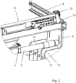
- the 2 shows a detailed view of the 1 with an enlarged representation of the guide 8, which is connected to the head piece 9.
- the guide 8 is arranged above the head piece 9 of the rod magazine 5 .
- the transfer device 6, which has the gripping device 7, can be moved transversely to the longitudinal extent of the rod magazine 5 by means of a driven gear wheel 12, which meshes with a toothed rack 13 of the guide 8.
Landscapes
- Engineering & Computer Science (AREA)
- Life Sciences & Earth Sciences (AREA)
- Geology (AREA)
- Mining & Mineral Resources (AREA)
- Mechanical Engineering (AREA)
- Physics & Mathematics (AREA)
- Environmental & Geological Engineering (AREA)
- Fluid Mechanics (AREA)
- General Life Sciences & Earth Sciences (AREA)
- Geochemistry & Mineralogy (AREA)
- Earth Drilling (AREA)
Claims (8)
- Dispositif de forage comprenant un châssis de forage (1) qui définit un axe de tige de forage (2), un magasin de tiges (5) pour une pluralité de tirs de tige (4) et un dispositif de transfert (6) pour le transfert d'un tir de tige (4) entre le magasin de tiges (5) et une position du tir de tige (4) dans la direction de l'axe de tige de forage (2), caractérisé en ce qu'un guide (8) pour un mouvement du dispositif de transfert (6) est présent sur le magasin de tiges (5) et le magasin de tiges (5) présente deux pièces de tête (9) s'étendant transversalement à la direction longitudinale du châssis de forage (1), sur chacune desquelles est disposé au moins un guide (8) pour le dispositif de transfert (6).
- Dispositif de forage selon la revendication 1, caractérisé en ce que le guide (8) est conçu pour un mouvement du dispositif de transfert (6) transversalement à l'axe de tige de forage (2).
- Dispositif de forage selon la revendication 1 ou 2, caractérisé en ce que les pièces de tête (9) du magasin de tiges (5) sont conçues de manière à être vissées et/ou soudées séparément à le châssis de forage (1).
- Dispositif de forage selon l'une des revendications 1 à 3, caractérisé en ce que les deux pièces de tête (9) du magasin de tiges (5) sont conçues pour être manipulées indépendamment l'une de l'autre.
- Dispositif de forage selon l'une des revendications 1 à 4, caractérisé en ce que le dispositif de transfert (6) présente deux dispositifs de préhension (7) pour saisir l'un des tirs de tige (4).
- Dispositif de forage selon l'une des revendications 1 à 5, caractérisé en ce que plusieurs éléments de séparation (11) sont disposés sur des pièces de tête (9) du magasin de tiges (5), qui s'étendent de manière décalée par rapport à l'axe de tige de forage (2) et le long de celui-ci, et la longueur sur laquelle les éléments de séparation (11) s'étendent de manière décalée le long de l'axe de tige de forage (2) est inférieure à la moitié de la longueur des tirs de tige (4).
- Dispositif de forage selon l'une des revendications 1 à 6, caractérisé en ce que le guide (8) présente une extension transversale à l'axe de tige de forage (2) supérieure à celle du magasin de tiges (5).
- Utilisation d'un dispositif de forage présentant un châssis de forage qui définit un axe de tige de forage (2), un magasin de tiges (5) pour une pluralité de tirs de tige (4) et un dispositif de transfert (6) pour le transfert d'un tir de tige (4) entre le magasin de tiges (5) et une position du tir de tige (4) dans la direction de l'axe de tige de forage (2), caractérisé en ce qu'un guide (8) formé sur le magasin de tiges (5) est utilisé pour un mouvement du dispositif de transfert (6), et le magasin de tiges (5) présente deux pièces de tête (9) s'étendant transversalement à la direction longitudinale du châssis de forage (1), sur chacune desquelles est disposé au moins un guide (8) pour le dispositif de transfert (6).
Applications Claiming Priority (1)
| Application Number | Priority Date | Filing Date | Title |
|---|---|---|---|
| DE102019001046.9A DE102019001046A1 (de) | 2019-02-13 | 2019-02-13 | Erdbohrvorrichtung und Verwendung einer Erdbohrvorrichtung |
Publications (2)
| Publication Number | Publication Date |
|---|---|
| EP3696372A1 EP3696372A1 (fr) | 2020-08-19 |
| EP3696372B1 true EP3696372B1 (fr) | 2023-03-29 |
Family
ID=69571935
Family Applications (1)
| Application Number | Title | Priority Date | Filing Date |
|---|---|---|---|
| EP20156844.1A Active EP3696372B1 (fr) | 2019-02-13 | 2020-02-12 | Dispositif de forage du sol et utilisation d'un dispositif de forage du sol |
Country Status (4)
| Country | Link |
|---|---|
| US (1) | US11293237B2 (fr) |
| EP (1) | EP3696372B1 (fr) |
| AU (1) | AU2020201008B2 (fr) |
| DE (1) | DE102019001046A1 (fr) |
Family Cites Families (7)
| Publication number | Priority date | Publication date | Assignee | Title |
|---|---|---|---|---|
| US4202653A (en) | 1976-04-30 | 1980-05-13 | Western Gear Corporation | Pipe handling apparatus |
| US8240968B2 (en) * | 2008-10-27 | 2012-08-14 | Laibe Corporation | Automated rod handling system |
| DE102009035277B4 (de) * | 2009-07-29 | 2023-10-26 | Tracto-Technik Gmbh & Co. Kg | Bohrvorrichtung |
| DE202011110844U1 (de) | 2011-09-07 | 2016-10-19 | Prime Drilling Gmbh | Rohrgestängeschuss-Manipulator |
| CN104165031B (zh) | 2014-08-12 | 2016-10-19 | 四川准达科技有限责任公司 | 钻机自动装卸钻杆装置 |
| CN105569584B (zh) * | 2015-03-27 | 2017-02-08 | 中国石油化工股份有限公司 | 油管自动化排放装置及方法 |
| CN206737862U (zh) * | 2017-04-26 | 2017-12-12 | 天津威猛机械制造有限公司 | 一种新型旋转式自动装杆器 |
-
2019
- 2019-02-13 DE DE102019001046.9A patent/DE102019001046A1/de active Pending
-
2020
- 2020-02-05 US US16/782,636 patent/US11293237B2/en active Active
- 2020-02-12 AU AU2020201008A patent/AU2020201008B2/en active Active
- 2020-02-12 EP EP20156844.1A patent/EP3696372B1/fr active Active
Also Published As
| Publication number | Publication date |
|---|---|
| US11293237B2 (en) | 2022-04-05 |
| AU2020201008B2 (en) | 2021-11-25 |
| US20200256138A1 (en) | 2020-08-13 |
| EP3696372A1 (fr) | 2020-08-19 |
| AU2020201008A1 (en) | 2020-08-27 |
| DE102019001046A1 (de) | 2020-08-13 |
Similar Documents
| Publication | Publication Date | Title |
|---|---|---|
| DE102009035277B4 (de) | Bohrvorrichtung | |
| EP3049607B1 (fr) | Dispositif de manipulation de tubes de forage d'un dispositif de forage profond | |
| EP0527460B1 (fr) | Procédé et dispositif pour forer des trous dans le sol ou dans la roche, notamment pour le placement de boulons d'ancrage à injection | |
| DE102012016878A1 (de) | Bohrstangenhandhabeeinrichtung, Bohrmast für eine Bohranlage und Verfahren zum Bewegen von Bohrstangen an einer Bohranlage | |
| EP2067924A1 (fr) | Installation de forage et procédé de forage | |
| DE1223776B (de) | Bohrvorrichtung fuer ein kontinuierliches und automatisches Niederbringen und Herausheben des Bohrrohrstranges bei Tiefbohrungen | |
| DE102018133369A1 (de) | Bohrvorrichtung und Bohrverfahren | |
| EP0796978A2 (fr) | Magasin pour tiges de forage | |
| EP1580398B1 (fr) | Appareil et méthode pour constructions souterraines | |
| DE3614199A1 (de) | Stangenhandhabungseinrichtung | |
| EP3696372B1 (fr) | Dispositif de forage du sol et utilisation d'un dispositif de forage du sol | |
| EP3699393B1 (fr) | Dispositif de forage du sol, système comprenant un dispositif de forage du sol, procédé de forage du sol et utilisation d'un dispositif de forage du sol | |
| DE102019001200B4 (de) | Erdbohrvorrichtung und Verwendung einer Erdbohrvorrichtung | |
| EP0825326B1 (fr) | Procédé et dispositif pour le forage horizontal et pour la manipulation de tiges de forage | |
| EP2839105B1 (fr) | Support de tubes et procédé pour l'acheminement et l'évacuation de corps tubulaires à destination et à partir d'une installation de forage | |
| DE202015008972U1 (de) | Bohranlage mit einem zwischen einer Transportstellung und einer Arbeitsstellung schwenkbaren Bohrmast | |
| DE3125013A1 (de) | Tiefbohrvorrichtung | |
| DE202022103789U1 (de) | Aushubschalungsvorrichtung, die für eine Vielzahl von Aushubverfahren für Tunnel geeignet ist | |
| EP2520758A2 (fr) | Appareil de forage et procédé de fonctionnement d'un appareil de forage | |
| DE3729561C2 (fr) | ||
| DE202015008973U1 (de) | Bohranlage mit einem zwischen einer Transportstellung und einer Arbeitsstellung schwenkbaren Mast | |
| WO2011060772A2 (fr) | Dispositif pour manipuler des tubes | |
| DE1817054A1 (de) | Strebeinrichtung fuer Streben im Untertagebergbau | |
| EP3029260B1 (fr) | Dispositif de forage de la terre | |
| EP3029263B1 (fr) | Dispositif de forage horizontal de la terre |
Legal Events
| Date | Code | Title | Description |
|---|---|---|---|
| PUAI | Public reference made under article 153(3) epc to a published international application that has entered the european phase |
Free format text: ORIGINAL CODE: 0009012 |
|
| STAA | Information on the status of an ep patent application or granted ep patent |
Free format text: STATUS: THE APPLICATION HAS BEEN PUBLISHED |
|
| AK | Designated contracting states |
Kind code of ref document: A1 Designated state(s): AL AT BE BG CH CY CZ DE DK EE ES FI FR GB GR HR HU IE IS IT LI LT LU LV MC MK MT NL NO PL PT RO RS SE SI SK SM TR |
|
| AX | Request for extension of the european patent |
Extension state: BA ME |
|
| STAA | Information on the status of an ep patent application or granted ep patent |
Free format text: STATUS: REQUEST FOR EXAMINATION WAS MADE |
|
| 17P | Request for examination filed |
Effective date: 20210218 |
|
| RBV | Designated contracting states (corrected) |
Designated state(s): AL AT BE BG CH CY CZ DE DK EE ES FI FR GB GR HR HU IE IS IT LI LT LU LV MC MK MT NL NO PL PT RO RS SE SI SK SM TR |
|
| STAA | Information on the status of an ep patent application or granted ep patent |
Free format text: STATUS: EXAMINATION IS IN PROGRESS |
|
| 17Q | First examination report despatched |
Effective date: 20210806 |
|
| GRAP | Despatch of communication of intention to grant a patent |
Free format text: ORIGINAL CODE: EPIDOSNIGR1 |
|
| STAA | Information on the status of an ep patent application or granted ep patent |
Free format text: STATUS: GRANT OF PATENT IS INTENDED |
|
| INTG | Intention to grant announced |
Effective date: 20220922 |
|
| GRAS | Grant fee paid |
Free format text: ORIGINAL CODE: EPIDOSNIGR3 |
|
| GRAA | (expected) grant |
Free format text: ORIGINAL CODE: 0009210 |
|
| STAA | Information on the status of an ep patent application or granted ep patent |
Free format text: STATUS: THE PATENT HAS BEEN GRANTED |
|
| AK | Designated contracting states |
Kind code of ref document: B1 Designated state(s): AL AT BE BG CH CY CZ DE DK EE ES FI FR GB GR HR HU IE IS IT LI LT LU LV MC MK MT NL NO PL PT RO RS SE SI SK SM TR |
|
| REG | Reference to a national code |
Ref country code: CH Ref legal event code: EP |
|
| REG | Reference to a national code |
Ref country code: DE Ref legal event code: R096 Ref document number: 502020002834 Country of ref document: DE |
|
| REG | Reference to a national code |
Ref country code: AT Ref legal event code: REF Ref document number: 1556771 Country of ref document: AT Kind code of ref document: T Effective date: 20230415 |
|
| REG | Reference to a national code |
Ref country code: IE Ref legal event code: FG4D Free format text: LANGUAGE OF EP DOCUMENT: GERMAN |
|
| REG | Reference to a national code |
Ref country code: LT Ref legal event code: MG9D |
|
| PG25 | Lapsed in a contracting state [announced via postgrant information from national office to epo] |
Ref country code: RS Free format text: LAPSE BECAUSE OF FAILURE TO SUBMIT A TRANSLATION OF THE DESCRIPTION OR TO PAY THE FEE WITHIN THE PRESCRIBED TIME-LIMIT Effective date: 20230329 Ref country code: NO Free format text: LAPSE BECAUSE OF FAILURE TO SUBMIT A TRANSLATION OF THE DESCRIPTION OR TO PAY THE FEE WITHIN THE PRESCRIBED TIME-LIMIT Effective date: 20230629 Ref country code: LV Free format text: LAPSE BECAUSE OF FAILURE TO SUBMIT A TRANSLATION OF THE DESCRIPTION OR TO PAY THE FEE WITHIN THE PRESCRIBED TIME-LIMIT Effective date: 20230329 Ref country code: LT Free format text: LAPSE BECAUSE OF FAILURE TO SUBMIT A TRANSLATION OF THE DESCRIPTION OR TO PAY THE FEE WITHIN THE PRESCRIBED TIME-LIMIT Effective date: 20230329 Ref country code: HR Free format text: LAPSE BECAUSE OF FAILURE TO SUBMIT A TRANSLATION OF THE DESCRIPTION OR TO PAY THE FEE WITHIN THE PRESCRIBED TIME-LIMIT Effective date: 20230329 |
|
| REG | Reference to a national code |
Ref country code: NL Ref legal event code: MP Effective date: 20230329 |
|
| PG25 | Lapsed in a contracting state [announced via postgrant information from national office to epo] |
Ref country code: SE Free format text: LAPSE BECAUSE OF FAILURE TO SUBMIT A TRANSLATION OF THE DESCRIPTION OR TO PAY THE FEE WITHIN THE PRESCRIBED TIME-LIMIT Effective date: 20230329 Ref country code: NL Free format text: LAPSE BECAUSE OF FAILURE TO SUBMIT A TRANSLATION OF THE DESCRIPTION OR TO PAY THE FEE WITHIN THE PRESCRIBED TIME-LIMIT Effective date: 20230329 Ref country code: GR Free format text: LAPSE BECAUSE OF FAILURE TO SUBMIT A TRANSLATION OF THE DESCRIPTION OR TO PAY THE FEE WITHIN THE PRESCRIBED TIME-LIMIT Effective date: 20230630 Ref country code: FI Free format text: LAPSE BECAUSE OF FAILURE TO SUBMIT A TRANSLATION OF THE DESCRIPTION OR TO PAY THE FEE WITHIN THE PRESCRIBED TIME-LIMIT Effective date: 20230329 |
|
| PG25 | Lapsed in a contracting state [announced via postgrant information from national office to epo] |
Ref country code: SM Free format text: LAPSE BECAUSE OF FAILURE TO SUBMIT A TRANSLATION OF THE DESCRIPTION OR TO PAY THE FEE WITHIN THE PRESCRIBED TIME-LIMIT Effective date: 20230329 Ref country code: RO Free format text: LAPSE BECAUSE OF FAILURE TO SUBMIT A TRANSLATION OF THE DESCRIPTION OR TO PAY THE FEE WITHIN THE PRESCRIBED TIME-LIMIT Effective date: 20230329 Ref country code: PT Free format text: LAPSE BECAUSE OF FAILURE TO SUBMIT A TRANSLATION OF THE DESCRIPTION OR TO PAY THE FEE WITHIN THE PRESCRIBED TIME-LIMIT Effective date: 20230731 Ref country code: ES Free format text: LAPSE BECAUSE OF FAILURE TO SUBMIT A TRANSLATION OF THE DESCRIPTION OR TO PAY THE FEE WITHIN THE PRESCRIBED TIME-LIMIT Effective date: 20230329 Ref country code: EE Free format text: LAPSE BECAUSE OF FAILURE TO SUBMIT A TRANSLATION OF THE DESCRIPTION OR TO PAY THE FEE WITHIN THE PRESCRIBED TIME-LIMIT Effective date: 20230329 |
|
| PG25 | Lapsed in a contracting state [announced via postgrant information from national office to epo] |
Ref country code: SK Free format text: LAPSE BECAUSE OF FAILURE TO SUBMIT A TRANSLATION OF THE DESCRIPTION OR TO PAY THE FEE WITHIN THE PRESCRIBED TIME-LIMIT Effective date: 20230329 Ref country code: PL Free format text: LAPSE BECAUSE OF FAILURE TO SUBMIT A TRANSLATION OF THE DESCRIPTION OR TO PAY THE FEE WITHIN THE PRESCRIBED TIME-LIMIT Effective date: 20230329 Ref country code: IS Free format text: LAPSE BECAUSE OF FAILURE TO SUBMIT A TRANSLATION OF THE DESCRIPTION OR TO PAY THE FEE WITHIN THE PRESCRIBED TIME-LIMIT Effective date: 20230729 |
|
| REG | Reference to a national code |
Ref country code: DE Ref legal event code: R097 Ref document number: 502020002834 Country of ref document: DE |
|
| PG25 | Lapsed in a contracting state [announced via postgrant information from national office to epo] |
Ref country code: DK Free format text: LAPSE BECAUSE OF FAILURE TO SUBMIT A TRANSLATION OF THE DESCRIPTION OR TO PAY THE FEE WITHIN THE PRESCRIBED TIME-LIMIT Effective date: 20230329 Ref country code: CZ Free format text: LAPSE BECAUSE OF FAILURE TO SUBMIT A TRANSLATION OF THE DESCRIPTION OR TO PAY THE FEE WITHIN THE PRESCRIBED TIME-LIMIT Effective date: 20230329 |
|
| PLBE | No opposition filed within time limit |
Free format text: ORIGINAL CODE: 0009261 |
|
| STAA | Information on the status of an ep patent application or granted ep patent |
Free format text: STATUS: NO OPPOSITION FILED WITHIN TIME LIMIT |
|
| 26N | No opposition filed |
Effective date: 20240103 |
|
| PGFP | Annual fee paid to national office [announced via postgrant information from national office to epo] |
Ref country code: DE Payment date: 20240321 Year of fee payment: 5 Ref country code: GB Payment date: 20240222 Year of fee payment: 5 |
|
| PG25 | Lapsed in a contracting state [announced via postgrant information from national office to epo] |
Ref country code: SI Free format text: LAPSE BECAUSE OF FAILURE TO SUBMIT A TRANSLATION OF THE DESCRIPTION OR TO PAY THE FEE WITHIN THE PRESCRIBED TIME-LIMIT Effective date: 20230329 |