EP3695959B1 - Verfahren zur herstellung eines mittels physikalischer dampfphasenabscheidung (pvd) beschichteten brillenglases und zwischenanordnung zur herstellung eines beschichteten brillenglases für dieses verfahren - Google Patents
Verfahren zur herstellung eines mittels physikalischer dampfphasenabscheidung (pvd) beschichteten brillenglases und zwischenanordnung zur herstellung eines beschichteten brillenglases für dieses verfahren Download PDFInfo
- Publication number
- EP3695959B1 EP3695959B1 EP20157324.3A EP20157324A EP3695959B1 EP 3695959 B1 EP3695959 B1 EP 3695959B1 EP 20157324 A EP20157324 A EP 20157324A EP 3695959 B1 EP3695959 B1 EP 3695959B1
- Authority
- EP
- European Patent Office
- Prior art keywords
- support body
- centering
- lens blank
- shaped
- centering reference
- Prior art date
- Legal status (The legal status is an assumption and is not a legal conclusion. Google has not performed a legal analysis and makes no representation as to the accuracy of the status listed.)
- Active
Links
Images


Classifications
-
- G—PHYSICS
- G02—OPTICS
- G02C—SPECTACLES; SUNGLASSES OR GOGGLES INSOFAR AS THEY HAVE THE SAME FEATURES AS SPECTACLES; CONTACT LENSES
- G02C7/00—Optical parts
- G02C7/02—Lenses; Lens systems ; Methods of designing lenses
-
- G—PHYSICS
- G02—OPTICS
- G02C—SPECTACLES; SUNGLASSES OR GOGGLES INSOFAR AS THEY HAVE THE SAME FEATURES AS SPECTACLES; CONTACT LENSES
- G02C7/00—Optical parts
- G02C7/02—Lenses; Lens systems ; Methods of designing lenses
- G02C7/024—Methods of designing ophthalmic lenses
-
- B—PERFORMING OPERATIONS; TRANSPORTING
- B05—SPRAYING OR ATOMISING IN GENERAL; APPLYING FLUENT MATERIALS TO SURFACES, IN GENERAL
- B05D—PROCESSES FOR APPLYING FLUENT MATERIALS TO SURFACES, IN GENERAL
- B05D1/00—Processes for applying liquids or other fluent materials
- B05D1/60—Deposition of organic layers from vapour phase
-
- B—PERFORMING OPERATIONS; TRANSPORTING
- B29—WORKING OF PLASTICS; WORKING OF SUBSTANCES IN A PLASTIC STATE IN GENERAL
- B29D—PRODUCING PARTICULAR ARTICLES FROM PLASTICS OR FROM SUBSTANCES IN A PLASTIC STATE
- B29D11/00—Producing optical elements, e.g. lenses or prisms
-
- B—PERFORMING OPERATIONS; TRANSPORTING
- B29—WORKING OF PLASTICS; WORKING OF SUBSTANCES IN A PLASTIC STATE IN GENERAL
- B29D—PRODUCING PARTICULAR ARTICLES FROM PLASTICS OR FROM SUBSTANCES IN A PLASTIC STATE
- B29D11/00—Producing optical elements, e.g. lenses or prisms
- B29D11/00009—Production of simple or compound lenses
-
- B—PERFORMING OPERATIONS; TRANSPORTING
- B29—WORKING OF PLASTICS; WORKING OF SUBSTANCES IN A PLASTIC STATE IN GENERAL
- B29D—PRODUCING PARTICULAR ARTICLES FROM PLASTICS OR FROM SUBSTANCES IN A PLASTIC STATE
- B29D11/00—Producing optical elements, e.g. lenses or prisms
- B29D11/0073—Optical laminates
-
- B—PERFORMING OPERATIONS; TRANSPORTING
- B29—WORKING OF PLASTICS; WORKING OF SUBSTANCES IN A PLASTIC STATE IN GENERAL
- B29D—PRODUCING PARTICULAR ARTICLES FROM PLASTICS OR FROM SUBSTANCES IN A PLASTIC STATE
- B29D11/00—Producing optical elements, e.g. lenses or prisms
- B29D11/00865—Applying coatings; tinting; colouring
-
- C—CHEMISTRY; METALLURGY
- C23—COATING METALLIC MATERIAL; COATING MATERIAL WITH METALLIC MATERIAL; CHEMICAL SURFACE TREATMENT; DIFFUSION TREATMENT OF METALLIC MATERIAL; COATING BY VACUUM EVAPORATION, BY SPUTTERING, BY ION IMPLANTATION OR BY CHEMICAL VAPOUR DEPOSITION, IN GENERAL; INHIBITING CORROSION OF METALLIC MATERIAL OR INCRUSTATION IN GENERAL
- C23C—COATING METALLIC MATERIAL; COATING MATERIAL WITH METALLIC MATERIAL; SURFACE TREATMENT OF METALLIC MATERIAL BY DIFFUSION INTO THE SURFACE, BY CHEMICAL CONVERSION OR SUBSTITUTION; COATING BY VACUUM EVAPORATION, BY SPUTTERING, BY ION IMPLANTATION OR BY CHEMICAL VAPOUR DEPOSITION, IN GENERAL
- C23C14/00—Coating by vacuum evaporation, by sputtering or by ion implantation of the coating forming material
- C23C14/0015—Coating by vacuum evaporation, by sputtering or by ion implantation of the coating forming material characterized by the colour of the layer
-
- C—CHEMISTRY; METALLURGY
- C23—COATING METALLIC MATERIAL; COATING MATERIAL WITH METALLIC MATERIAL; CHEMICAL SURFACE TREATMENT; DIFFUSION TREATMENT OF METALLIC MATERIAL; COATING BY VACUUM EVAPORATION, BY SPUTTERING, BY ION IMPLANTATION OR BY CHEMICAL VAPOUR DEPOSITION, IN GENERAL; INHIBITING CORROSION OF METALLIC MATERIAL OR INCRUSTATION IN GENERAL
- C23C—COATING METALLIC MATERIAL; COATING MATERIAL WITH METALLIC MATERIAL; SURFACE TREATMENT OF METALLIC MATERIAL BY DIFFUSION INTO THE SURFACE, BY CHEMICAL CONVERSION OR SUBSTITUTION; COATING BY VACUUM EVAPORATION, BY SPUTTERING, BY ION IMPLANTATION OR BY CHEMICAL VAPOUR DEPOSITION, IN GENERAL
- C23C14/00—Coating by vacuum evaporation, by sputtering or by ion implantation of the coating forming material
- C23C14/04—Coating on selected surface areas, e.g. using masks
- C23C14/042—Coating on selected surface areas, e.g. using masks using masks
- C23C14/044—Coating on selected surface areas, e.g. using masks using masks using masks to redistribute rather than totally prevent coating, e.g. producing thickness gradient
-
- C—CHEMISTRY; METALLURGY
- C23—COATING METALLIC MATERIAL; COATING MATERIAL WITH METALLIC MATERIAL; CHEMICAL SURFACE TREATMENT; DIFFUSION TREATMENT OF METALLIC MATERIAL; COATING BY VACUUM EVAPORATION, BY SPUTTERING, BY ION IMPLANTATION OR BY CHEMICAL VAPOUR DEPOSITION, IN GENERAL; INHIBITING CORROSION OF METALLIC MATERIAL OR INCRUSTATION IN GENERAL
- C23C—COATING METALLIC MATERIAL; COATING MATERIAL WITH METALLIC MATERIAL; SURFACE TREATMENT OF METALLIC MATERIAL BY DIFFUSION INTO THE SURFACE, BY CHEMICAL CONVERSION OR SUBSTITUTION; COATING BY VACUUM EVAPORATION, BY SPUTTERING, BY ION IMPLANTATION OR BY CHEMICAL VAPOUR DEPOSITION, IN GENERAL
- C23C14/00—Coating by vacuum evaporation, by sputtering or by ion implantation of the coating forming material
- C23C14/22—Coating by vacuum evaporation, by sputtering or by ion implantation of the coating forming material characterised by the process of coating
- C23C14/24—Vacuum evaporation
-
- C—CHEMISTRY; METALLURGY
- C23—COATING METALLIC MATERIAL; COATING MATERIAL WITH METALLIC MATERIAL; CHEMICAL SURFACE TREATMENT; DIFFUSION TREATMENT OF METALLIC MATERIAL; COATING BY VACUUM EVAPORATION, BY SPUTTERING, BY ION IMPLANTATION OR BY CHEMICAL VAPOUR DEPOSITION, IN GENERAL; INHIBITING CORROSION OF METALLIC MATERIAL OR INCRUSTATION IN GENERAL
- C23C—COATING METALLIC MATERIAL; COATING MATERIAL WITH METALLIC MATERIAL; SURFACE TREATMENT OF METALLIC MATERIAL BY DIFFUSION INTO THE SURFACE, BY CHEMICAL CONVERSION OR SUBSTITUTION; COATING BY VACUUM EVAPORATION, BY SPUTTERING, BY ION IMPLANTATION OR BY CHEMICAL VAPOUR DEPOSITION, IN GENERAL
- C23C14/00—Coating by vacuum evaporation, by sputtering or by ion implantation of the coating forming material
- C23C14/22—Coating by vacuum evaporation, by sputtering or by ion implantation of the coating forming material characterised by the process of coating
- C23C14/50—Substrate holders
-
- C—CHEMISTRY; METALLURGY
- C23—COATING METALLIC MATERIAL; COATING MATERIAL WITH METALLIC MATERIAL; CHEMICAL SURFACE TREATMENT; DIFFUSION TREATMENT OF METALLIC MATERIAL; COATING BY VACUUM EVAPORATION, BY SPUTTERING, BY ION IMPLANTATION OR BY CHEMICAL VAPOUR DEPOSITION, IN GENERAL; INHIBITING CORROSION OF METALLIC MATERIAL OR INCRUSTATION IN GENERAL
- C23C—COATING METALLIC MATERIAL; COATING MATERIAL WITH METALLIC MATERIAL; SURFACE TREATMENT OF METALLIC MATERIAL BY DIFFUSION INTO THE SURFACE, BY CHEMICAL CONVERSION OR SUBSTITUTION; COATING BY VACUUM EVAPORATION, BY SPUTTERING, BY ION IMPLANTATION OR BY CHEMICAL VAPOUR DEPOSITION, IN GENERAL
- C23C14/00—Coating by vacuum evaporation, by sputtering or by ion implantation of the coating forming material
- C23C14/22—Coating by vacuum evaporation, by sputtering or by ion implantation of the coating forming material characterised by the process of coating
- C23C14/54—Controlling or regulating the coating process
- C23C14/542—Controlling the film thickness or evaporation rate
-
- G—PHYSICS
- G02—OPTICS
- G02B—OPTICAL ELEMENTS, SYSTEMS OR APPARATUS
- G02B1/00—Optical elements characterised by the material of which they are made; Optical coatings for optical elements
- G02B1/10—Optical coatings produced by application to, or surface treatment of, optical elements
-
- G—PHYSICS
- G02—OPTICS
- G02B—OPTICAL ELEMENTS, SYSTEMS OR APPARATUS
- G02B1/00—Optical elements characterised by the material of which they are made; Optical coatings for optical elements
- G02B1/10—Optical coatings produced by application to, or surface treatment of, optical elements
- G02B1/11—Anti-reflection coatings
- G02B1/113—Anti-reflection coatings using inorganic layer materials only
- G02B1/115—Multilayers
-
- G—PHYSICS
- G02—OPTICS
- G02B—OPTICAL ELEMENTS, SYSTEMS OR APPARATUS
- G02B1/00—Optical elements characterised by the material of which they are made; Optical coatings for optical elements
- G02B1/10—Optical coatings produced by application to, or surface treatment of, optical elements
- G02B1/12—Optical coatings produced by application to, or surface treatment of, optical elements by surface treatment, e.g. by irradiation
-
- C—CHEMISTRY; METALLURGY
- C03—GLASS; MINERAL OR SLAG WOOL
- C03C—CHEMICAL COMPOSITION OF GLASSES, GLAZES OR VITREOUS ENAMELS; SURFACE TREATMENT OF GLASS; SURFACE TREATMENT OF FIBRES OR FILAMENTS MADE FROM GLASS, MINERALS OR SLAGS; JOINING GLASS TO GLASS OR OTHER MATERIALS
- C03C17/00—Surface treatment of glass, not in the form of fibres or filaments, by coating
- C03C17/06—Surface treatment of glass, not in the form of fibres or filaments, by coating with metals
- C03C17/09—Surface treatment of glass, not in the form of fibres or filaments, by coating with metals by deposition from the vapour phase
-
- C—CHEMISTRY; METALLURGY
- C03—GLASS; MINERAL OR SLAG WOOL
- C03C—CHEMICAL COMPOSITION OF GLASSES, GLAZES OR VITREOUS ENAMELS; SURFACE TREATMENT OF GLASS; SURFACE TREATMENT OF FIBRES OR FILAMENTS MADE FROM GLASS, MINERALS OR SLAGS; JOINING GLASS TO GLASS OR OTHER MATERIALS
- C03C17/00—Surface treatment of glass, not in the form of fibres or filaments, by coating
- C03C17/22—Surface treatment of glass, not in the form of fibres or filaments, by coating with other inorganic material
- C03C17/23—Oxides
- C03C17/245—Oxides by deposition from the vapour phase
-
- C—CHEMISTRY; METALLURGY
- C03—GLASS; MINERAL OR SLAG WOOL
- C03C—CHEMICAL COMPOSITION OF GLASSES, GLAZES OR VITREOUS ENAMELS; SURFACE TREATMENT OF GLASS; SURFACE TREATMENT OF FIBRES OR FILAMENTS MADE FROM GLASS, MINERALS OR SLAGS; JOINING GLASS TO GLASS OR OTHER MATERIALS
- C03C2218/00—Methods for coating glass
- C03C2218/10—Deposition methods
- C03C2218/15—Deposition methods from the vapour phase
-
- G—PHYSICS
- G02—OPTICS
- G02C—SPECTACLES; SUNGLASSES OR GOGGLES INSOFAR AS THEY HAVE THE SAME FEATURES AS SPECTACLES; CONTACT LENSES
- G02C7/00—Optical parts
- G02C7/10—Filters, e.g. for facilitating adaptation of the eyes to the dark; Sunglasses
Definitions
- the present invention regards a method for making an eyeglass lens coated by means of physical vapor deposition PVD and an intermediate assembly for the production of a coated eyeglass lens for said method, according to the preamble of the respective independent claims.
- the present method and intermediate assembly are intended to be employed in the eyeglass field for making eyeglass lenses coated with a coating layer, in particular colored, and in particular eyeglass lenses coated with a mirrored coating layer.
- the present intermediate assembly is intended to be employed in the present method for making eyeglass lenses coated with a coating layer, such coating layer being shaped and oriented with respect to the perimeter edge of the coated eyeglass lens itself.
- the invention is therefore inserted in the context of the industrial field of eyeglasses and production methods for making eyeglasses.
- eyeglasses In order to render eyeglasses more externally pleasing, eyeglasses have been on the market for years with "mirrored" lenses, i.e. coated with a coating layer, which is susceptible of reflecting, like a mirror, the image of the surrounding environment over which the eyeglasses are directed.
- mirrored lenses i.e. coated with a coating layer, which is susceptible of reflecting, like a mirror, the image of the surrounding environment over which the eyeglasses are directed.
- mirroring two methods are mainly known for making a mirrored lens, hereinbelow also termed “mirroring” methods, which provide for coating the eyeglass lens with a coating layer by means of physical vapor phase deposition, known in the technical jargon of the field also by its acronym PVD (physical vapor deposition). It is therefore the coating layer deposited in the aforesaid method to confer the mirrored coloring to the coated eyeglass lens.
- PVD physical vapor deposition
- a first mirroring method of known type provides for coating the eyeglass lens with a thin layer of metal material, which is provided with good light reflection qualities and thus confers the desired mirrored aspect to the lens.
- a second mirroring method of known type provides for coating the lens with a thin film composed of multiple layers of different materials, and generally composed of multiple layers of two materials alternated with each other.
- the materials used in such second mirroring method of known type are generally inorganic oxides, such as for example titanium dioxide (TiO2), silicon dioxide (SiO2), zirconium dioxide (ZrO2), hafnium dioxide (HfO2), aluminum oxide (Al2O3), silicon oxide (SiO) and magnesium oxide (MgO2), or they are inorganic salts, such as magnesium fluoride (MgF2) and cerium fluoride (CeF2).
- the mirrored coloring obtained with such second mirroring method of known type is not due to the color of the material that forms the various layers (which in fact, if taken separately, are transparent or have whitish color) but instead is due to an optical effect of interference between the various components of the light that is reflected and refracted from every single layer.
- the various components of reflected and refracted light are susceptible of being added together, producing phenomena of optical interference that cause a light radiation reflected by the thin film, which is only centered on some wavelengths of the visible spectrum and hence allows perceiving a specific coloring of the thin film, which depends on the type of material that constitutes the various layers, on the number of superimposed layers and on the thickness thereof.
- Both of the above-described mirroring methods provide for depositing, by means of a PVD process, at least one coating layer on the lens to be colored (whether this is the metal material layer or the multiple layers of different materials that constitute the thin film), which generally has a nanometric thickness.
- the PVD processes of known type generally occur within a mirroring chamber where a vacuum is made, in which the material that one wishes to deposit (such as zirconium, titanium or chromium in the case of deposition of the layer of metal material, or titanium oxide or silicon oxide in the case of deposition of the thin film) is arranged together with a lens blank to be coated in order to achieve the mirroring effect.
- the material that one wishes to deposit such as zirconium, titanium or chromium in the case of deposition of the layer of metal material, or titanium oxide or silicon oxide in the case of deposition of the thin film
- lens blank it is indicated a lens generally with circular shape and provided with greater size than the coated eyeglass lens that is obtained therefrom in order to be mounted on the frame of the eyeglasses.
- lens it is intended a substantially transparent body, preferably made of plastic or glass, and substantially sheet-like, i.e. provided with a substantially negligible thickness with respect to its surface extension, which can be provided with two flat faces or with at least one curved face, and which is susceptible of being coated, on at least one of its faces, with a coating layer.
- the aforesaid lens blanks allow standardizing the steps of producing and coating the eyeglass lenses, indeed such steps are executed on blanks with identical shape and size, which are subsequently cut into the desired eyeglass lens shape.
- the abovementioned PVD processes of known type provide for arranging the material that one wishes to deposit on the lens in a suitable crucible arranged inside the mirroring chamber. Such material is then heated up to making it sublimate (or evaporate) in vapor phase, hence generating a flow of particles in vapor phase that is dispersed in the vacuum mirroring chamber.
- the lens blanks are generally arranged in abutment seats made in suitable supports, for example of the type indicated in the enclosed figure A, which are oriented so that the lenses intercept the flow of metal material in vapor phase.
- suitable supports for example of the type indicated in the enclosed figure A, which are oriented so that the lenses intercept the flow of metal material in vapor phase.
- the supports of known type generally have spherical cap shape and are positioned within the mirroring chamber with the crucible substantially at the center of such spherical cap.
- the abutment seats of the supports are provided with a through opening susceptible of being crossed by the flow of particles in vapor phase which are dispersed starting from the crucible, so as to allow the deposition of the coating layer on the face of the lenses that closes such through opening.
- One drawback of the aforesaid mirroring methods lies in the fact that the coloring, obtained with the coating layer, does not have a uniform distribution on the lens blank, but rather has a faded distribution, with an intensity and a coloring which vary from the perimeter edge of the lens blank towards the interior of the blank itself.
- the intensity and the coloring of the lens blanks coated with the methods of known type briefly described above are strongly linked to the thickness of the coating layers deposited by means of the PVD processes.
- the intensity of the mirrored coloring is linked to the thickness of the metal material layer that is deposited on the lens blank, in which a thicker metal material layer often corresponds with a more significant and covering mirroring, while a thinner metal material layer corresponds with a less significant and less covering mirroring, at which the lens blank is more transparent.
- the second mirroring method allows obtaining mirrored coloring with different colors in accordance with the thickness of the various layers that constitute the thin film, and hence, different colors correspond with different thicknesses.
- the lens blanks coated with the methods of known type, employing PVD processes are thus provided with a coating layer provided with thinner perimeter annular edge, whose coloring is faded as one moves radially away from the center of the lens blanks.
- Such annular edge is due to the fact that the flow of particles in vapor phase (whether this is formed by metal material particles or by inorganic compound particles) is diffused in the mirroring chamber in a substantially random manner and the particles in vapor phase that constitute it can be intercepted by the centering template before hitting the lens blank.
- the flow of particles in vapor phase internally comprises particles directed towards the lens blank perpendicular to its surface and particles directed in a tilted manner with respect to the surface itself.
- the latter can be intercepted by the centering template and, in particular, by the perimeter walls which delimit the through openings thereof, which thus prevent such particles from reaching the lens blank.
- the perimeter walls of the through openings project a shadow cone on the lens blank, which is darker as one approaches the wall itself, and defines an annular portion of the through opening in which the particles in vapor phase that advance along tilted trajectories do not reach the lens blank but are intercepted by the centering template to an increasingly greater extent as one approaches the perimeter wall itself.
- the areas of the lens blank affected by such shadow cone i.e. the perimeter edge of the lens blank, arranged in the vicinity of such perimeter walls
- a coating layer of thinner thickness which generates such faded edge, with respect to the areas not intercepted by the shadow cone, i.e. with respect to a central area of the blank, which is not affected by the presence of the perimeter walls.
- the methods for producing coated lenses of known type provide for cutting the lens blank, excluding the faded edge so as to avoid the presence of even only one portion of the aforesaid faded edge in the cut eyeglass lens, which would be negatively perceived on the market.
- the coating on the blank is distributed in a covering manner without accounting for the orientation of the blank. The consequent cutting step therefore does not account for the orientation of the blank during the coating step.
- thin supports are known that are provided with shallow through openings so as to minimize the extension of the faded edge and attain lens blanks coated with a coating layer of uniform thickness, from which the eyeglass lens can be easily cut with the desired shape and coated in a uniform manner.
- US 5,325,812 discloses a method and an arrangement for vacuum process coating which make use of an assembly comprising a carrying ring having a circular opening for holding a circular a lens.
- the lens is held in the carrying ring by means of spring clasp, which is enveloped around the lens and is provided with two holdings grips engaged to the carrying ring.
- the faded edge on the lens blanks that is attained with the above-described methods of known type cannot be currently employed for conferring an appreciable aesthetic effect to the lenses.
- the problem underlying the present invention is therefore that of overcoming the drawbacks shown by the methods of known type, by providing a method for making an eyeglass lens coated by means of physical vapor deposition PVD and an intermediate assembly employable in such method which allow easily obtaining designs with oriented shape on the lenses.
- a further object of the present invention is to provide a method for coating eyeglass lenses that allows obtaining a faded edge effect which is arranged within the final lens and which is simultaneously aesthetically appreciable.
- a further object of the present invention is to provide a method for coating eyeglass lenses which allows obtaining a faded effect which designs desired shapes and geometries.
- a further object of the present invention is to provide a method for coating eyeglass lenses which is simple to achieve.
- a further object of the present invention is to provide a method for coating eyeglass lenses which can be easily implemented, starting from the methods of known type.
- a further object of the present invention is to provide a method for coating eyeglass lenses which can be implemented with already-existing instrumentation and with the employing of the present intermediate assembly.
- a further object of the present invention is to provide an intermediate assembly employable in such method for making coated eyeglass lenses, which comprises a support body which is inexpensive to make and simple to use and which allows making oriented designs on the lenses.
- the method and the support body that will be discussed hereinbelow are intended for making lenses coated by means of physical vapor deposition PVD, in which a coating layer 10 is deposited on a lens blank 1, from which the desired coated lens (also indicated hereinbelow with the expression "final lens L") is intended to be obtained.
- the present method is adapted to coat the lens blank 1 with the coating layer 10 shaped in many different forms.
- the coating layer 10 deposited with the present method is suitably oriented along the blank of lens 1, i.e. it is deposited at a desired position known a priori, in order to obtain a desired aesthetic effect.
- the present method advantageously allows to deposit the coating layer 10 at a certain position inside a final lens L which is desired to be obtained starting from the blank of lens 1 coated with the aforementioned coating layer 10.
- oriented will mean that an object is positioned in a predetermined position, known with respect to a specific reference center.
- the coating layer 10 deposited with the present method is provided with a "mirrored" coloring, i.e. susceptible of reflecting, like a mirror, the image of the surrounding environment over which the eyeglasses are directed.
- a mirrored coloring i.e. susceptible of reflecting, like a mirror, the image of the surrounding environment over which the eyeglasses are directed.
- the aforesaid coating layer 10 can also be provided with a non-mirrored coloring, without departing from the scope of the present patent.
- the method, object of the present invention comprises a step of arranging a lens blank 1 provided with at least one first centering reference 15.
- the lens blank 1 is advantageously of the type known in the eyeglass field for the production of eyeglass lenses and especially for the production of colored lenses for sunglasses, or lenses that are ophthalmic and colored for graduated sunglasses.
- the present lens blanks 1 are made of the different materials used today on the market for producing lenses, such as of plastic/organic material or of glass, in particular mineral glass.
- the first centering reference 15 is advantageously attained in the form of a tooth projecting from the lens blank 1, and preferably it is attained in the form of two teeth projecting from the lens blank 1, e.g. at two diametrically-opposite positions of the aforesaid lens blank 1.
- each projecting tooth is adapted to act as first centering reference 15.
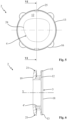
- the method, object of the present invention also provides for a step of arranging a support body 2 for the lens blank 1, as can be appreciated for example in figure 3 .
- such support body 2 is provided with a first abutment seat 3 adapted to house the lens blank 1, which is thus preferably counter-shaped with respect to the lens blank 1 itself in order to retain it at its interior by means of shape coupling.
- the support body 2 is also provided with at least one second centering reference 25 with respect to which the first centering reference 15 of the lens blank 1 is susceptible of being oriented, which is intended to be housed in the first abutment seat 3.
- the aforesaid centering reference 25 is advantageously attained in the form of a sunken female seat made in the support body 2, and preferably sunken starting from the first abutment seat 3.
- the female seat of the centering reference 25 is advantageously counter-shaped with respect to the first centering reference 15 and is adapted to be engaged via shape coupling with the latter.
- the support body 2 is provided with two second centering references 25 made in the form of two female seats susceptible of housing the two projecting teeth.
- first centering reference 15 is made in the form of a sunken female seat in the lens blank 1
- second centering reference 25 is made in the form of a tooth projecting from the support body 2, and in particular projecting inside the first abutment seat 3 in order to be engaged via shape coupling with the female seat of the lens blank 1.
- the support body 2 is also provided with at least one first shaped and through opening 4, which is oriented with respect to the second centering reference 25 in the sense that the relative position thereof is defined and known.
- the first shaped and through opening 4 is advantageously delimited by at least one perimeter wall 4', which is extended in a manner passing through the support body 2 starting from a first bottom wall 12 of the first abutment seat 3, as is for example indicated in the enclosed figures 3 , 5 and 18 .
- the first abutment seat 3 is provided with a plurality of first through openings 4, which are delimited by a plurality of perimeter walls 4' arranged in an angled manner with respect to each other.
- the support body 2 has substantially cylindrical form (being intended that it preferably has an axial extension like a projection of a flat figure along an axis) and is extended along a longitudinal axis Y between an upper face 18, from which the first abutment seat 3 is obtained, and an opposite lower face 19.
- the perimeter walls 4' of each first shaped and through opening 4 are preferably extended between the first bottom wall 12 of the first abutment seat 3 and the lower face 19 of the support body 2 for a predefined height.
- such predefined height preferably coincides with the difference between the height of the support body 2, defined between its upper and lower faces 18, 19, and the depth of the first abutment seat 3 defined by the distance between the upper face 18 and the first bottom wall 12.
- several perimeter walls 4' are extended starting from the bottom wall 12 of the first abutment seat 3 for a reduced height with respect to the predefined height between the first bottom wall 12 of the first abutment seat 3 and the lower face 19 of the support body 2.
- each first shaped and through opening 4 have a predefined tilt with respect to the longitudinal axis Y of the support body 2.
- each first shaped and through opening 4 are substantially extended parallel to the longitudinal axis Y of the support body 2.
- several first through openings 4 are widened towards the lower face 19, being delimited by perimeter walls 4' arranged in a tilted manner with respect to the longitudinal axis Y of the support body 2.
- each first shaped and through opening 4 are arranged along a shaped profile 24 which confers a pre-established shape (design) to the first shaped and through opening 4.
- the shape of the first shaped and through opening 4 is provided with variable shapes and sizes based on the aesthetic effect that one wishes to obtain on the lens blank 1 with the method, object of the present invention, as better specified hereinbelow.
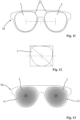
- the first shaped and through opening 4 is advantageously shaped in the form of an eyeglass lens, and in particular is shaped in the form of the final lens L that one wishes to attain. More clearly, the first shaped and through opening 4 substantially has the shape and size of a specific final lens L intended to be mounted on a specific eyeglass frame M.
- the shape of the first shaped and through opening 4 can thus vary based on the eyeglass model on which the final lens L is intended to be mounted.
- the first shaped and through opening 4 can have drop form, or be substantially circular, rectangular, trapezoidal or have yet another shape.
- the first shaped and through opening 4 can be shaped in right lens or left lens form in order to be mounted on eyeglasses provided with final lenses L, mirrored with respect to the nosepiece, as is for example represented in the enclosed figure 13 .
- the first shaped and through opening 4 can be shaped in the form of an eyeglass lens that does not coincide with the form of the final lens L.
- the first shaped and through opening 4 can be attained in the same form as the final lens L but it can be provided with a different size.
- the first shaped and through opening 4 can be shaped in forms and sizes that do not coincide with the shape of the final lens L intended to be mounted on the eyeglass frame M, e.g. it can be shaped in strip form (in accordance with the second embodiment illustrated in the enclosed figures 14, 15 ) or in triangle form (in accordance with the third embodiment illustrated in figure 18 ) or in still other forms without departing from the protective scope of the present patent.
- the aforesaid first shaped and through openings 4 are oriented with respect to the second centering reference 25 and preferably are centered with respect to the first abutment seat 3.
- the present method also comprises a step of arranging a centering template 5 provided with at least one second abutment seat 6, adapted to house the support body 2, and with at least one second through opening 7 preferably open on the second abutment seat 6, as indicated hereinbelow.
- the centering template 5 arranged in the present method can be of the type already known for housing the lens blanks 1 for known coating methods, so as to be easily found on the market.
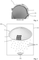
- the centering template 5 is advantageously obtained with a wall shaped in the form of a spherical cap, having a convex external surface and a concave internal surface, and on such wall, a plurality of the aforesaid second abutment seats 6 are made as illustrated in the enclosed figures 1 and 2 .
- each second abutment seat 6 is extended starting from the external surface of the centering template 5 up to a second bottom wall, against which the lens blank 1 according to already-known methods (as indicated in the enclosed figure A) or the support body 2 (as indicated in the enclosed figure 4 ) according to the present method is susceptible of abutting.
- each second abutment seat 6 a corresponding second through opening 7 is also arranged, preferably centered with respect to the first shaped and through opening 4 of the support body 2 intended to be housed in the second abutment seat.
- each second through opening 7 is extended between the second bottom wall of the second abutment seat 6 up to the opposite internal surface of the centering template 5 in spherical cap form.
- the method, object of the present invention also comprises an assembly step, in which the lens blank 1 is housed in the first abutment seat 3 of the support body 2 to close the first shaped and through opening 4.
- this assembly step is therefore assembled an assembly which is intended for being employed in the present method and which includes the support body 2 and the lens blank 1 mounted on said support body 2.
- the lens blank 1 is arranged with an internal face thereof directed towards the first shaped and through opening 4 and partially in abutment (at its peripheral edge) against the bottom wall 12 of the first abutment seat 3 of the support body 2.
- the lens blank 1 is housed in the first abutment seat 3, orienting the first centering reference 15 with respect to the second centering reference 25, i.e. in other words arranging the lens blank in a known position with respect to the support body 2 due to the mutual orientation between the two centering references 15 and 25.
- the lens blank 1 is housed in the first abutment seat 3 with its first centering reference 15 arranged in a position that is predefined and known with respect to the second centering reference 25.
- the first and the second centering reference 15, 25 are attained in the form of projecting tooth and female seat
- the lens blank 1 in the assembly step the lens blank 1 is housed in the first abutment seat 3 with its projecting tooth inserted in the female seat of the support body 2.
- the first and the second centering reference 15, 25 are attained in the form of reference notches respectively made on the lens blank 1 and on the support body 2 and, in the assembly step, the lens blank 1 is housed in the first abutment seat 3 with its reference notch facing towards the reference notch of the support body 2.
- the first and the second centering reference 15, 25 are defined by the perimeter shape of the lens blank 1 and of the first abutment seat 3 that are counter-shaped with respect to each other and, in the assembly step, the lens blank 1 is oriented such that it can be inserted to size in the first abutment seat 3.
- the aforesaid assembly step also provides for housing the support body 2 in the second abutment seat 6 of the centering template 5 with the first shaped and through opening 4 and the second through opening 7 substantially aligned with each other (see the enclosed figures 7A-C ).
- the support body 2 is provided with a peripheral profile suitably counter-shaped with respect to the second abutment seat 6 such that it can be inserted to size in such second abutment seat 6 and retained at its interior via shape coupling.
- the support body 2 is preferably provided with at least one third centering reference 16 and the centering template 5 is provided with at least one fourth centering reference 26.
- the support body 2 in operation, in the assembly step the support body 2 is housed in the second abutment seat 6, orienting the third centering reference 16 with respect to the fourth centering reference 26.
- the third centering reference 16 is made in the form of a projecting ear and the fourth centering reference 26 is made in the form of a female seat counter-shaped with respect to the projecting ear, which is adapted to house the latter and preferably to retain it via shape coupling (see for example figure 4 ).
- the support body 2 is provided with two or more third centering references 16, for example it is provided with four projecting ears as indicated in the enclosed figures, and the centering template 5 is provided with two or more corresponding fourth centering references 26 and, in particular, is provided with a number of fourth centering references 26 at least equal to the number of the third centering references 16, e.g. it is provided with four female seats.
- the support body 2 is provided with a step 21 that is sunken starting from its peripheral profile at the lower face 19 (see figure 6 ), which is susceptible of abutting against a corresponding perimeter wall of the second through opening 7 of the centering template 5, as indicated in the enclosed figures 7A, 7B and 7C .
- the support body 2 is partially housed inside the second through opening 7 of the centering template 5 with the first shaped and through opening 4 and the second through opening 7 which have a section of their axial extension in common.
- the aforesaid assembly step provides for mounting multiple support bodies 2 on the centering template 5; each of such support bodies 2 is housed in a corresponding second abutment seat 6 and is susceptible of housing a corresponding lens blank 1 (see figure 1 ).
- the present method also comprises at least one step of coating the lens blank 1 by means of physical vapor deposition PVD, in which a flow of particles in vapor phase is directed towards the lens blank 1, through the second through opening 7 and through the first shaped and through opening 4, and is deposited on the lens blank 1, forming a coating layer 10 thereon.
- PVD physical vapor deposition
- the particles in vapor phase employed in the aforesaid coating step can advantageously be made of any one material that can be deposited by means of PVD process, i.e. any one material that is solid at room temperature and pressure, which is susceptible of passing from the solid state to the vapor state and vice versa only by means of physical transformations.
- the particles in vapor phase employed in the coating step are made of materials per se provided with a mirrored coloring (such as metal materials), or they are made of materials susceptible of reflecting the light that hits thereon, creating phenomena of optical interference such to reproduce a mirrored coloring (such as inorganic salts or oxides).
- a mirrored coloring such as metal materials
- the particles in vapor phase employed in the coating step are made of materials per se provided with a mirrored coloring (such as metal materials), or they are made of materials susceptible of reflecting the light that hits thereon, creating phenomena of optical interference such to reproduce a mirrored coloring (such as inorganic salts or oxides).
- metal materials employable in the present method are for example zirconium (Zr), titanium (Ti) and chromium (Cr).
- employable inorganic oxides are for example titanium dioxide (TiO2), silicon dioxide (SiO2), zirconium dioxide (ZrO2), hafnium dioxide (HfO2), aluminum oxide (Al2O3), silicon oxide (SiO) and magnesium oxide (MgO2).
- employable inorganic salts are for example magnesium fluoride (MgF2) and cerium fluoride (CeF2).
- the aforesaid coating step occurs within a mirroring chamber 101 of an apparatus for vapor phase physical deposition 100 (hereinbelow indicated with its acronym PVD).
- PVD vapor phase physical deposition
- the PVD apparatus 100 intended to be employed in the present method is advantageously an apparatus of type known to the man skilled in the art and therefore not described in detail hereinbelow.
- the coating step provides for arranging the lens blank 1, associated with the support body 2 and the centering template 5, in the mirroring chamber 101 of the PVD apparatus 100 together with one or more materials to be deposited on the lens blank 1, e.g. of the type indicated above.
- such coating step provides for bringing the mirroring chamber 101 under vacuum, or in any case to a pressure lower than or equal to 10 -2 mbar and preferably to a pressure lower than or equal to 10 -4 mbar.
- the coating step provides for heating the material to be deposited until it is brought to vapor phase.
- heating of the material to be deposited is advantageously attained by means of electrical heating elements, such as heating elements arranged at a crucible 102 of the material to be deposited itself, and such heating elements are adapted to heat the material to be deposited by Joule effect.
- the heated material to be deposited is then susceptible of passing to the vapor phase in the form of the aforesaid particles in vapor phase, which tend to be expanded in the mirroring chamber 101 under vacuum, creating the flow of particles in vapor phase.
- the particles in vapor phase are also susceptible of condensing substantially instantaneously when they contact into contact with the lens blank 1, which is preferably maintained at a temperature considerably lower than the temperature of the particles in vapor phase, which, thus condensing, deposit the coating layer 10.
- the coating step is extended for a time period comprised between 30 and 60 minutes and preferably for about 45 minutes, i.e. up to obtaining the coating layer 10 provided with a desired average thickness, and in particular with an average thickness comprised between several tens and several hundreds of nanometers.
- the coating layer 10 deposited in the aforesaid coating step is provided with an exposed profile 20 with shape substantially coinciding with the first shaped and through opening 4 and preferably with size smaller than the entire lens blank 1.
- the flow of particles in vapor phase is susceptible of condensing substantially instantaneously when it comes into contact with a surface at a temperature considerably lower than its own, depositing the coating layer 10. Then, only the fraction of the flow of particles in vapor phase, that impacts the portion of the lens blank 1 placed to close the first shaped and through opening 4, is susceptible of being deposited on the lens blank 1, thus defining the exposed profile 20 of the coating layer 10 substantially counter-shaped with respect to the shaped profile 24 of the first shaped and through opening 4 itself. In this manner, it is thus possible to obtain the coating layer 10 shaped according to the desired shapes and sizes, i.e. shaped according to the desired shapes and sizes of the first shaped and through opening 4.
- the support body 2 can be provided with a plurality of first shaped and through openings 4 and consequently the coating layer 10 can comprise a plurality of exposed profiles 20 with shape substantially coinciding with the plurality of first shaped and through openings 4.
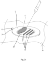
- the present method also comprises a cutting step in which the lens blank 1 is cut along a cutting profile 23 which is shaped in the form of eyeglass lens and preferably is shaped in a form coinciding with the form of the final lens L that one wishes to obtain.
- the aforesaid cutting profile 23 (indicated with dashed line in figure 11 and in figure 21 ) is oriented with respect to the first centering reference 15 of the lens blank 1 so as to cut the lens blank 1, accounting for the position of the shape of the coating layer 10.
- the first centering reference 15 is oriented with respect to the second centering reference 25 of the support body 2, with respect to which the shaped profile 24 of the first shaped and through opening 4 is oriented, which in turn coincides with the exposed profile 20 of the coating layer 10.
- the cutting profile 23 is oriented with respect to the exposed profile 20 of the reference layer 10 and preferably coincides with the latter as indicated in the enclosed figure 8 .
- the cutting step is preferably executed by means of cutting means, for example comprising a laser beam, which are advantageously automatically driven by control means susceptible of guiding them in order to cut the lens blank 1 along the cutting profile 23; see for example the enclosed figure 21 , in which the aforesaid cutting step is schematically represented and in which the laser beam is adapted to define a cutting line 32 on the lens blank 1 that is arranged along the preset cutting profile 23.
- cutting means for example comprising a laser beam
- the lens blank 1 is advantageously associated with a second template 30, provided with a fifth centering reference 31, with respect to which the first centering reference 15 is newly oriented.
- the present method allows automating the step of cutting the lens blanks 1, thus speeding up the production process of the mirrored eyeglass lenses with the present method.
- the present method allows attaining innumerable aesthetic effects on the lens blank 1. For example, it allows varying the shape and size of the coating layer 10 by varying the shape and size of the first shaped and through openings 4. Or, it allows varying the coloring type of the coating layer 10 by varying the material to be deposited on the lens blank 1. In addition, the present method allows attaining, on a same lens blank 1, multiple different coating layers 10 by varying the number of coating steps.
- the present method can provide for hitting the lens blank 1 with coating layers 10 of different coloring by varying the material to be deposited in the coating step.
- the coating layer 10 deposited in the coating step is constituted by one or more metal materials, mixed together in a uniform compound, which are susceptible of conferring to the coating layer 10 the mirrored coloring typical of the specific metal material.
- the coating layer 10 is constituted by multiple separate substrates of different materials and preferably by two or more separate substrates of two materials alternated with each other.
- the materials which constitute the various substrates are preferably inorganic salts or oxides (in particular of the above-listed type), which are susceptible of reflecting and refracting the light and, superimposed on each other, are susceptible of producing phenomena of optical interference such to allow perceiving a mirrored coloring of the coating layer 10, which depends on the type of material with which each substrate is attained, on the number of such superimposed substrates and on their thickness.
- the light that hits the various substrates is susceptible of being divided into a reflected component and a refracted component, the latter is propagated into the substrate itself up to intercepting the subsequent substrate, at which it is newly divided into a reflected component and a refracted component.
- the various components of light reflected and refracted by the various superimposed substrates are then susceptible of being added to each other according to the laws of optics and produce phenomena of optical interference that determine the formation of a light radiation reflected by the coating layer 10, which is advantageously centered only over several wavelengths of the visible spectrum and thus confers a specific mirrored coloring to the coating layer 10.
- each substrate of the coating layer 10 it is possible to size each substrate of the coating layer 10 so as to obtain the desired final coloring.
- the aforesaid second embodiment provides for arranging the plurality of materials to be deposited within the mirroring chamber 101, in corresponding crucibles 102 and then provides for heating each crucible 102 at different time intervals, so as to produce different flows of particles in vapor phase at different times.
- each substrate of the coating layer 10 is advantageously composed of only one material and does not contain impurities of other materials.
- the coating layer 10 deposited on the lens blank 1 is constituted by a substantially uniform compound of the different heated materials.
- the present method can also provide for a different number of coating steps, and in particular it can provide for two or more coating steps in which the lens blank 1 is coated with different coating layers 10.
- the present method can comprise two or more coating steps spaced from each other by corresponding assembly steps in which the lens blank 1 is extracted from the first abutment seat 3 and repositioned in the same in an angled position, with the first centering reference 15 oriented with respect to a different second centering reference 25.
- first centering reference 15 attained in the form of a projecting tooth is advantageously engaged in a different second centering reference 25 attained in the form of a female seat in order to vary the orientation of the first centering reference 15 with respect to the second centering reference 25.
- the lens blank 1 is oriented with respect to a different second centering reference 25 in a known manner, according to angles predefined in design step so as to make, on the lens blank 1, multiple coating layers 10 that are at least partially superimposed and angled with respect to each other, for example in order to recreate an aesthetic effect in which the different coating layers 10 design the weave of a fabric.
- the present method can comprise two or more coating steps spaced from each other by corresponding assembly steps in which the support body 2 is extracted from the second abutment seat 6 and repositioned in the same in a further angled position, with the third centering reference 16 oriented with respect to a different fourth centering reference 26.
- the third centering reference 16 attained in the form of a projecting ear is advantageously engaged in a different fourth centering reference 26 attained in the form of a female seat in order to vary the orientation of the third centering reference 16 with respect to the fourth centering reference 26.
- the support body 2 is oriented with respect to a different fourth centering reference 26 in a known manner, according to angles predefined in design step.
- the present method can comprise two or more coating steps spaced from each other by corresponding assembly steps in which the lens blank 1 is extracted from the first abutment seat 3 of the support body 2 and is inserted in a different first abutment seat 3 of a different support body 2 having at least one different first shaped and through opening 4.
- the expression "different first shaped and through opening 4" means that the different support body 2, provided in a subsequent assembly step, is equipped with a first shaped and through opening 4 which develops along a shaped profile 24 different from that along which the first shaped and through opening 4 of the support body 2 provided in the previous assembly step develops.
- the aforementioned different first shaped and through opening 4 is advantageously delimited by perimeter walls 4' having a predefined height or a tilt which differs from the perimeter walls 4' of the first shaped and through opening 4 of the support body 2 provided in the previous assembly phase.
- each coating layer 10 obtained in the aforesaid two or more coating steps can be provided with a different coloring in order to create further aesthetic effects.
- each coating step advantageously produces a faded perimeter edge 11 of the coating layer 10 due to partial interference of the support body 2 with the flow of particles in vapor phase intended to be deposited on the lens blank 1.
- the flow of particles in vapor phase advantageously comprises a plurality of particles 103 suspended at its interior, each of which advancing towards the lens blank 1 with its own trajectory, arranged at least partially randomly within the flow of particles in vapor phase.
- the particles 103 that are moved along trajectories substantially parallel to the perimeter walls 4' of the first shaped and through opening 4 are susceptible of entirely crossing such first shaped and through opening 4 and of being deposited on the internal face of the lens blank 1. Otherwise, the particles 103 which are moved along tilted trajectories with respect to the perimeter walls 4' can be intercepted by the support body 2 (or by the centering template 5) and do not impact against the lens blank 1.
- the lower face 19 of the support body 2 is susceptible of intercepting at least one fraction of the particles 103 that advance along tilted trajectories towards the lens blank 1 and in particular the fraction of particles 103 directed towards the perimeter walls 4' of the first shaped and through opening 4. Consequently, the coating layer 10 which is deposited at such perimeter walls 4' is susceptible of being provided with a smaller thickness with respect to a central zone of the coating layer 10 itself, which substantially is not affected by the presence of the perimeter walls 4', and thus determines the aforesaid faded perimeter edge 11.
- the coating layer 10 at the faded perimeter edge 11 is provided with a thickness which diminishes from the thickness present in the central zone up to a minimum thickness at the exposed profile 20.
- the coating layer 10 at the faded perimeter edge 11 is indicated as diminishing with a substantially step-like progression: however, it is intended that such representation is only schematic and non-limiting, and in particular the coating layer 10, at its faded perimeter edge 11, advantageously diminishes with a ramp progression, in which steps are not recognizable.
- the aforesaid faded perimeter edge 11 is provided with a faded coloring that diminishes from the central zone of the coating layer 10, where its thickness is maximal, towards its external perimeter, where its thickness is minimal, thus as schematically indicated in figures 9 and 10 .
- the coloring of the coating layer 10 depends on its thickness, and by the thickness of the various substrates that constitute it.
- the faded perimeter edge 11 is extended from the exposed profile 20 of the coating layer 10 for a width proportional to the predefined height of the perimeter walls 4' of the first shaped and through opening 4.
- perimeter walls 4' that are lifted for predefined greater heights are susceptible of intercepting particles 103 directed towards an annular band of the lens blank 1 of greater width.
- the perimeter walls 4' of the first shaped and through opening 4 are therefore calibrated with a predefined height such to obtain the faded perimeter edge 11 of desired width.
- the perimeter walls 4' of the first shaped and through opening 4 can be equipped with predefined tilt with respect to the longitudinal axis Y.
- the perimeter walls 4' can be arranged tilted with respect to the longitudinal axis Y and in particular they can be arranged tilted by a predefined angle such to reduce or cancel the width of the faded perimeter edge 11.
- the perimeter walls 4' which are tilted away from the center of the first shaped and through opening 4 are susceptible of intercepting a reduced fraction of the flow of particles in vapor phase and hence they are susceptible of projecting a shadow of smaller extension.
- perimeter walls 4' which are tilted towards the center of the first shaped and through opening 4 are susceptible of intercepting a greater fraction of the flow of particles in the vapor phase and hence they are susceptible of projecting a shadow of greater extension.
- the present method then provides for calibrating the height and/or the predefined tilt of the perimeter walls 4' based on the width of the faded perimeter edge 11 that one wishes to obtain.
- the present method can provide for calibrating the height and/or the predefined tilt of the perimeter walls 4' so as to obtain a coating layer substantially free of the faded perimeter edge 11.
- the coating layer 10 produced with the present method i.e. centered with respect to the cutting edge 20 and provided with the faded perimeter edge 11, confers to the final lens L an external/aesthetic effect that is particularly appreciable and not attainable with the coating methods known up to now.
- the cutting step provides for cutting the lens blank 1 along the cutting profile 23, which for at least one section is arranged at the faded perimeter edge 11 so as to thus obtain a final lens L in which the coating layer 10 diminishes with the perimeter edge 11 faded towards the perimeter of the lens itself.
- the present method is thus advantageously adapted to exploit the faded perimeter edge 11 suitably calibrated as an aesthetic motif, which cannot be attained with the presently known coating methods.
- the coating layer 10 it is possible to create a final lens L entirely covered by the coating layer 10, which is provided with the faded perimeter edge 11 arranged at the external perimeter of the final lens L itself.
- the present method for making a coated eyeglass lens employs an assembly comprising the support body 2 and the blank lens 1 mounted on the support body 2 itself. Said assembly is referred to below as "intermediate” since it relates to an intermediate stage of the present method.
- Also forming the object of the present invention is an intermediate assembly for the production of a coated eyeglass lens intended to be employed in a method for making an eyeglass lens coated by means of physical vapor deposition PVD, and in particular intended to be used in the method, object of the present invention, described above, and regarding which the same reference nomenclature will be employed for the sake of description simplicity.
- the support body 2 of the present intermediate assembly is advantageously intended to be housed in a second abutment seat 6 of a centering template 5 that is per se known to the man skilled in the art and generally employed in PVD apparatuses 100, also per se known to the man skilled in the art.
- the support body 2 of the present intermediate assembly is provided with an external profile shaped like a lens blank 1, i.e. substantially circular, and preferably is provided with dimensions substantially corresponding to those of the lens blanks 1 themselves.
- the support body 2 is configured for being housed in the second abutment seat 6, in particular housed to size in the aforesaid second abutment seat 6.
- the support body 2 preferably has substantially cylindrical form (being intended that it preferably has an axial extension like the projection of a figure along an axis) and is extended along a longitudinal axis Y between an upper face 18 and an opposite lower face 19, intended to abut against a second bottom wall of the second abutment seat 6 of the centering template 5.
- the intermediate assembly comprises a lens blank 1 to be coated which is provided with at least one first centering reference 15, preferably of the type described above.
- the intermediate assembly comprises a support body 2 for said lens blank 1, the support body 2 comprises a first abutment seat 3 in which is housed the lens blank 1 to be coated.
- the first abutment seat 3 is advantageously obtained starting from the upper face 18 of the support body 2 and is preferably delimited by a bottom wall 12 and by an annular shoulder 13 that is counter-shaped with respect to the lens blank 1.
- the bottom surface 12 of the first abutment seat 3 is provided with a concavity substantially counter-shaped with respect to the convexity of the lens blank 1, as can be appreciated in the enclosed figures 6 , 7A-C and 15 .
- the support body 2 also comprises at least one second centering reference 25, with respect to which a first centering reference 15 of the lens blank 1 housed in the first abutment seat 3, is oriented (i.e. placed in a relative known position).
- the second centering reference 25 is made in the form of a female seat, sunken starting from the first abutment seat 3 and, in particular, starting from its annular shoulder 13. Additionally, the aforesaid female seat is counter-shaped with respect to the first centering reference 15, made in the form of a tooth projecting from the lens blank 1, and is susceptible of being engaged with the latter via shape coupling.
- the opposite embodiment solution in which the first centering reference 15 is made in the form of a sunken female seat in the lens blank 1 and the second centering reference 25 is made in the form of a tooth projecting from the support body 2, and projecting inside the first abutment seat 3 in order to be engaged via shape coupling with the female seat of the lens blank 1.
- the support body 2 comprises two or more centering references 25, preferably of the type attained in female seat form, and in particular comprises a number at least equal to and preferably greater than the number of first centering references 15 of the lens blank 1.
- the support body 2 is adapted to house, in its first abutment seat 3, the lens blank 1 in multiple positions that are predefined and oriented with respect to the second centering references 25.
- the support body 2 comprises at least one first shaped and through opening 4, oriented with respect to the second centering reference 25.
- the first shaped and through opening 4 is intended to be crossed by a flow of particles in vapor phase in order to deposit on the lens blank 1, housed in the first abutment seat 3, a coating layer 10, which is provided with an exposed profile 20 with shape substantially coinciding with the shape of the first shaped and through opening 4.
- the support body 2 is provided with two or more first shaped and through openings 4, which are shaped in pre-established shapes so as to obtain coating layers 10 provided with the desired exposed profiles 20.
- each first shaped and through opening 4 is advantageously delimited by at least one perimeter wall 4', which is extended starting from the first abutment seat 3 for a predefined height and is arranged along a shaped profile 24, whose position is known with respect to the second centering reference 25.
- the shaped profile 24, along which the perimeter walls 4' of the aforesaid first shaped and through opening 4 are arranged, is suitably shaped in the desired shape and size.
- the shaped profile 24 can be shaped in eyeglass lens form and in particular in the shape of a specific final lens L intended to be mounted on a specific eyeglass frame M. Such shape can then vary based on the model of eyeglasses that one wishes to attain.
- the shaped profile 24 can be shaped in drop form or have substantially circular shape, rectangular shape, trapezoidal shape or have yet another shape without departing from the protective scope of the present patent.
- the shaped profile 24 can be shaped in forms different from the form of the final lens L intended to be made by the lens blank 1, e.g. it can be shaped in lens sector form, or in strip form (as indicated in the enclosed figure 14 ) or in geometric form (as indicated in the enclosed figure 18 ) or in still other shapes without departing from the scope of the present patent.
- the perimeter walls 4' are extended between the first bottom wall 12 of the first abutment seat 3 and the lower face 19 of the support body 2 and are extended substantially parallel to the longitudinal axis Y of the support body 2 itself for a predefined height substantially coinciding with the difference between the height of the support body 2, between its upper and lower faces 18, 19, and the depth of the first abutment seat 3, between the upper face 18 and the first bottom wall 12.
- the perimeter walls 4' are extended for a predefined height comprised between 0.1 and 5 cm and preferably comprised between 0.5 and 3 cm.
- the perimeter walls 4' of the first through openings 4 can be extended starting from the bottom wall 12 of the first abutment seat 3 for a reduced height with respect to the predefined height between the first bottom wall 12 of the first abutment seat 3 and the lower face 19 of the support body 2.
- such perimeter walls 4' can be advantageously arranged in a tilted manner with respect to the longitudinal axis Y of the support body 2 in order to delimit tapered first through openings 4.
- the first shaped and through opening 4 is intended to be crossed by a flow of particles in vapor phase in order to deposit the coating layer 10 on the lens blank 1.
- the flow of particles in vapor phase is of the type attained by means of a PVD apparatus 100, e.g. via thermal evaporation of one or more materials to be deposited, such as metal materials, inorganic oxides or inorganic salts.
- the flow of particles in vapor phase which crosses the first shaped and through opening 4 is susceptible of depositing the coating layer 10 provided with the exposed profile 20 with shape substantially coinciding with the shaped profile 24 of the first shaped and through opening 4.
- the aforesaid coating layer 10, starting from its exposed profile 20, is provided with a faded perimeter edge 11 of limited thickness, which is due to a partial interference of the support body 2 itself with the flow of particles in vapor phase.
- each first shaped and through opening 4 is provided with a predefined height that is calibrated in order to obtain a desired width of the faded perimeter edge 11 of the coating layer 10, and such height is proportional to said predefined height, in accordance with that indicated above with reference to the method, object of the present invention.
- the present support body 2 is suitably designed starting from the shape of the final lenses L that one wishes to obtain. More in detail, in accordance with the enclosed figures 11 and 12 , the design of the support body 2 preferably starts from the determination of the geometric center of each of the two final lenses L (right and left) to be associated with a desired eyeglass frame M. In particular, the determination of the geometric center advantageously occurs by framing the shape of the final lens L in a rectangle and tracing the directrix lines, such as the diagonals or the medians or a diagonal and a median, as indicated in the example of figure 12 .
- the design of the support body 2 preferably provides for sizing the first housing seat 3 in a manner such that the latter retains via shape coupling the lens blank 1 that one intends to house therein.
- the second centering references 25 are sized based on the first centering references 15 of the lens blank 1 intended to be housed in the first abutment seat 3.
- the first abutment seat 3 is positioned within the support body 2 in a manner such that the geometric center of the final lens L to be obtained coincides with the geometric center of the first abutment seat 3.
- the first shaped and through opening 4 is then advantageously sized, which is suitably shaped along the shaped profile 24 substantially coinciding with the exposed profile 20 that one wishes to give to the coating layer 10.
- first shaped and through opening 4 is advantageously positioned within the first housing seat 3 in a manner such that the coating layer 10 is positioned, within the final lens L that one wishes to obtain, at a pre-established position, based on the desired aesthetic effect.
- the design of the support body 2 advantageously provides for determining a function indicative of the position of the perimeter walls 4' of the first shaped and through opening 4 with respect to the second centering reference 25. Consequently, once the position of the perimeter walls 4' is determined with respect to the second centering reference 25, also the position of the same perimeter walls 4' is determined with respect to the first centering reference 15.
- the step of designing the support body 2 also provides for sizing its external profile in a manner such to allow inserting the support body 2 itself to size within the second abutment seat 6 of the centering template 5.
- the support body 2 advantageously comprises at least one third centering reference 16, with respect to which the support body 2 is susceptible of being oriented in the centering template 5.
- the third centering reference 16 is advantageously attained in the form of a projecting ear 16, which is projectingly extended from an external wall of the support body 2 and is susceptible of being housed in a fourth centering reference 26 of the centering template 5, advantageously made in the form of a female seat.
- the female seat of the fourth centering reference 26 is advantageously obtained starting from the second abutment seat 6 of the centering template 5, which, in the mirroring methods of known type, is generally aimed to house the projecting tooth of the lens blank 1.
- the support body 2 is provided with a step 21 that is sunken starting from its peripheral profile at its lower face 19.
- the aforesaid step 21 is intended to abut against a corresponding perimeter wall of a second through opening 7 of the centering template 5 obtained starting from the second abutment seat 6, so as to ensure a more stable positioning of the support body 2 in the second abutment seat 6.
- the method and the intermediate assembly thus conceived therefore attain the pre-established objects that is, they allow to make an eyeglass lens and an eyewear provided with lenses coated with a coating layer suitably oriented to achieve a desired aesthetic effect.
Landscapes
- Chemical & Material Sciences (AREA)
- Engineering & Computer Science (AREA)
- Mechanical Engineering (AREA)
- Chemical Kinetics & Catalysis (AREA)
- Materials Engineering (AREA)
- Metallurgy (AREA)
- Organic Chemistry (AREA)
- Physics & Mathematics (AREA)
- Health & Medical Sciences (AREA)
- Ophthalmology & Optometry (AREA)
- Manufacturing & Machinery (AREA)
- General Physics & Mathematics (AREA)
- Optics & Photonics (AREA)
- General Health & Medical Sciences (AREA)
- Inorganic Chemistry (AREA)
- Eyeglasses (AREA)
- Surface Treatment Of Optical Elements (AREA)
Claims (15)
- Verfahren zur Herstellung eines mittels physikalischer Dampfphasenabscheidung (PVD) beschichteten Brillenglases, wobei das Verfahren Folgendes umfasst:- einen Schritt der Vorbereitung eines Linsenrohlings (1), der mit mindestens einem ersten Zentrierbezug (15) versehen ist;- einen Schritt der Vorbereitung eines Trägerkörpers (2), der mit einem ersten Aufnahmesitz (3), der geeignet ist, den genannten Linsenrohling (1) unterzubringen, mit mindestens einem zweiten Zentrierbezug (25) und mit mindestens einer ersten profilierten und durchgehenden Öffnung (4), die im Verhältnis zu dem zweiten Zentrierbezug (25) ausgerichtet ist, ausgestattet ist;- einen Schritt der Vorbereitung einer Zentrierschablone (5), die mit einem zweiten Aufnahmesitz (6), der geeignet ist, den genannten Trägerkörper (2) aufzunehmen, und mit mindestens einer zweiten durchgehenden Öffnung (7) versehen ist;- einen Montageschritt, bei dem:- der genannte Linsenrohling (1) in dem ersten Aufnahmesitz (3) des genannten Trägerkörpers (2) die genannte mindestens eine erste profilierte und durchgehende Öffnung (4) verschließend untergebracht ist und so den genannten ersten Zentrierbezug (15) im Verhältnis zu dem genannten zweiten Zentrierbezug (25) ausrichtet, und- der genannte Trägerkörper (2) in dem zweiten Aufnahmesitz (6) der genannten Zentrierschablone (5) untergebracht ist, wobei die genannte erste profilierte und durchgehende Öffnung (4) und die genannte zweite durchgehende Öffnung (7) im Wesentlichen miteinander ausgerichtet sind;- mindestens einen Schritt der Beschichtung des genannten Linsenrohlings (1) mittels physikalischer Dampfphasenabscheidung PVD, wobei ein Teilchenstrom in Dampfphase die genannte zweite und erste profilierte und durchgehende Öffnung (7, 4) überquerend auf den genannten Linsenrohling (1) gerichtet wird und sich auf dem genannten Linsenrohling (1) absetzt und auf diesem mindestens eine Beschichtungsschicht (10) bildet, die mit einem freiliegenden Profil (20) versehen ist, dessen Form im Wesentlichen mit der ersten profilierten und durchgehenden Öffnung (4) des genannten Trägerkörpers (2) übereinstimmt;- einen Schneidschritt, bei dem der genannte Linsenrohling (1) entlang eines Schneidprofils (23) eingeschnitten wird, das in Form eines Brillenglases profiliert ist und im Verhältnis zu dem genannten ersten Zentrierbezug (15) ausgerichtet ist.
- Verfahren nach Anspruch 1, dadurch gekennzeichnet, dass der genannte erste Zentrierbezug (15) in Form eines von dem genannten Linsenrohling (1) vorstehenden Zahns ausgeführt ist und der genannte zweite Zentrierbezug (25) in Form einer in den genannten Trägerkörper (2) versenkten Aufnahme ausgeführt ist, die im Verhältnis zu dem genannten ersten Zentrierbezug (15) ein Gegenprofil bildet und geeignet ist, bei dem genannten Montageschritt durch formschlüssige Verbindung mit dem genannten ersten Zentrierbezug (15) in Eingriff gebracht zu werden.
- Verfahren nach einem beliebigen der vorangegangenen Ansprüche, dadurch gekennzeichnet, dass die erste profilierte und durchgehende Öffnung (4) des genannten Trägerkörpers (2) in Form eines Brillenglases profiliert ist.
- Verfahren nach einem beliebigen der vorangegangenen Ansprüche, dadurch gekennzeichnet, dass das genannte Schneidprofil (23) mit dem freiliegenden Profil (20) der genannten Beschichtungsschicht (10) übereinstimmt.
- Verfahren nach einem beliebigen der vorangegangenen Ansprüche, dadurch gekennzeichnet, dass der genannte Trägerkörper (2) mit einem dritten Zentrierbezug (16) versehen und die genannte Zentrierschablone (5) mit einem vierten Zentrierbezug (26) versehen ist;
wobei der genannte Montageschritt vorsieht, den genannten Trägerkörper (2) in dem zweiten Aufnahmesitz (6) der genannten Zentrierschablone (5) unterzubringen und so den genannten dritten Zentrierbezug (16) im Verhältnis zu dem genannten vierten Zentrierbezug (26) auszurichten. - Verfahren nach Anspruch 5, dadurch gekennzeichnet, dass die genannte Zentrierschablone (5) zwei oder mehr der genannten vierten Zentrierbezüge (26) umfasst;
wobei das genannte Verfahren zwei oder mehr Beschichtungsschritte umfasst, zwischen denen entsprechende Montageschritte erfolgen, wobei der genannte Trägerkörper (2) aus dem genannten zweiten Aufnahmesitz (6) entfernt und in diesen in einer abgewinkelten Position neu positioniert wird, wobei der genannte dritte Zentrierbezug (16) im Verhältnis zu einem anderen vierten Zentrierbezug (26) der genannten Zentrierschablone (5) ausgerichtet ist. - Verfahren nach Anspruch 1, dadurch gekennzeichnet, dass der genannte Trägerkörper (2) zwei oder mehr der genannten zweiten Zentrierbezüge (25) aufweist;
wobei das genannte Verfahren zwei oder mehr Beschichtungsschritte umfasst, zwischen denen entsprechende Montageschritte erfolgen, wobei der genannte Linsenrohling (1) aus dem ersten Aufnahmesitz (3) des genannten Trägerkörpers (2) entnommen und in diesem in einer abgewinkelten Position neu positioniert wird, wobei der genannte erste Zentrierbezug (15) im Verhältnis zu einem anderen zweiten Zentrierbezug (25) des genannten Trägerkörpers (2) ausgerichtet ist. - Verfahren nach einem beliebigen der vorangegangenen Ansprüche, dadurch gekennzeichnet, dass es zwei oder mehr Beschichtungsschritte umfasst, zwischen denen entsprechende Montageschritte erfolgen, wobei der genannte Linsenrohling (1) aus dem genannten ersten Aufnahmesitz (3) des genannten Trägerkörpers (2) entnommen und in einen anderen ersten Aufnahmesitz (3) eines anderen Trägerkörpers (2) eingesetzt wird, der mindestens eine andere genannte erste profilierte und durchgehende Öffnung (4) aufweist.
- Verfahren nach einem beliebigen der vorangegangenen Ansprüche, dadurch gekennzeichnet, dass der genannte Trägerkörper (2) mit einer Vielzahl von genannten ersten profilierten und durchgehenden Öffnungen (4) versehen ist und die genannte Beschichtungsschicht (10) eine Vielzahl von genannten freiliegenden Profilen (20) mit einer Form umfasst, die im Wesentlichen mit der genannten Vielzahl erster profilierter und durchgehender Öffnungen (4) übereinstimmt.
- Verfahren nach einem beliebigen der vorangegangenen Ansprüche, dadurch gekennzeichnet, dass der genannte Beschichtungsschritt einen verlaufenden Umfangsrand (11) der genannten Beschichtungsschicht (10) durch partielle Interferenz des genannten Trägerkörpers (2) mit dem genannten Teilchenstrom in Dampfphase ergibt;
wobei der genannte Schneidschritt vorsieht, den genannten Linsenrohling (1) entlang des genannten Schneidprofils (23) einzuschneiden, das auf mindestens einem Abschnitt mit dem genannten verlaufenden Umfangsrand (11) übereinstimmt. - Zwischenanordnung zur Herstellung eines beschichteten Brillenglases, die dazu bestimmt ist, in einem Verfahren zur Herstellung eines mittels physikalischer Dampfphasenabscheidung (PVD) beschichteten Brillenglases eingesetzt zu werden; wobei die genannte Zwischenanordnung Folgendes umfasst:- einen zu beschichtenden Linsenrohling (1), der mit mindestens einem ersten Zentrierbezug (15) versehen ist;- einen Trägerkörper (2) für den genannten Linsenrohling (1), der Folgendes umfasst:wobei diese Zwischenanordnung dadurch gekennzeichnet ist, dass:- einen ersten Aufnahmesitz (3), in dem der genannte Linsenrohling (1) untergebracht ist;- mindestens einen zweiten Zentrierbezug (25), im Verhältnis zu dem der erste Zentrierbezug (15) des in dem genannten ersten Aufnahmesitz (3) untergebrachten genannten Linsenrohlings (1) ausgerichtet ist;- mindestens eine erste profilierte und durchgehende Öffnung (4), die im Verhältnis zu dem genannten zweiten Zentrierbezug (25) ausgerichtet ist und dazu bestimmt ist, von einem Teilchenstrom in Dampfphase überquert zu werden, um eine Beschichtungsschicht (10) auf dem Linsenrohling (1) abzusetzen;- der zweite Zentrierbezug (25) des genannten Trägerkörpers (2) in Form einer ausgehend von dem genannten ersten Aufnahmesitz (3) versenkten Aufnahme ausgeführt und geeignet ist, durch formschlüssige Verbindung mit dem genannten ersten Zentrierbezug (15) in Eingriff gebracht zu werden, der in Form eines von dem genannten Linsenrohling (1) vorstehenden Zahns ausgeführt ist, oder- der genannte erste Zentrierbezug (15) in Form einer in den Linsenrohling (1) versenkten Aufnahme ausgeführt ist und der zweite Zentrierbezug (25) in Form eines von dem genannten Stützkörper (2) vorstehenden Zahns ausgeführt ist, der im Inneren des genannten ersten Aufnahmesitzes (3) vorsteht, um durch formschlüssige Verbindung mit der Aufnahme des genannten Linsenrohlings (1) in Eingriff gebracht zu werden.
- Zwischenanordnung nach Anspruch 11, dadurch gekennzeichnet, dass der erste Aufnahmesitz (3) des genannten Trägerkörpers (2) durch eine Rückwand (12) begrenzt wird, von der aus die genannte erste profilierte und durchgehende Öffnung (4) verläuft, und durch einen ringförmigen Ansatz (13), der im Verhältnis zu dem genannten Linsenrohling (1) ein Gegenprofil bildet.
- Zwischenanordnung nach Anspruch 12, dadurch gekennzeichnet, dass die Rückwand (12) des genannten Trägerkörpers (2) mit einer im Wesentlichen im Verhältnis zur Konvexität des genannten Linsenrohlings (1) ein Gegenprofil bildenden Konkavität versehen ist.
- Zwischenanordnung nach einem beliebigen der Ansprüche 11 bis 13, dadurch gekennzeichnet, dass der genannte Trägerkörper (2) mindestens einen dritten Zentrierbezug (16) umfasst, im Verhältnis zu dem der genannte Trägerkörper (2) geeignet ist, in einer Zentrierschablone (5) ausgerichtet zu werden.
- Zwischenanordnung nach einem beliebigen der Ansprüche 11 bis 14, dadurch gekennzeichnet, dass die genannte mindestens eine erste profilierte und durchgehende Öffnung (4) durch mindestens eine Umfangswand (4') begrenzt ist, die über eine zuvor festgelegte Höhe verläuft und mit einer zuvor festgelegten Neigung versehen ist, wobei die genannte zuvor festgelegte Höhe und/oder die genannte zuvor festgelegte Neigung entsprechend kalibriert sind, um die mit einem verlaufenden Umfangsrand (11) versehene genannte Beschichtungsschicht (10) in gewünschter Breite und proportional zu der genannten zuvor festgelegten Höhe und/oder Neigung zu erhalten.
Applications Claiming Priority (1)
| Application Number | Priority Date | Filing Date | Title |
|---|---|---|---|
| IT102019000002339A IT201900002339A1 (it) | 2019-02-18 | 2019-02-18 | Metodo per realizzare una lente di occhiali rivestita mediante deposizione fisica di vapore pvd e corpo di supporto per uno sbozzato di lente |
Publications (3)
| Publication Number | Publication Date |
|---|---|
| EP3695959A1 EP3695959A1 (de) | 2020-08-19 |
| EP3695959B1 true EP3695959B1 (de) | 2025-01-01 |
| EP3695959C0 EP3695959C0 (de) | 2025-01-01 |
Family
ID=66776698
Family Applications (1)
| Application Number | Title | Priority Date | Filing Date |
|---|---|---|---|
| EP20157324.3A Active EP3695959B1 (de) | 2019-02-18 | 2020-02-14 | Verfahren zur herstellung eines mittels physikalischer dampfphasenabscheidung (pvd) beschichteten brillenglases und zwischenanordnung zur herstellung eines beschichteten brillenglases für dieses verfahren |
Country Status (4)
| Country | Link |
|---|---|
| US (1) | US11774777B2 (de) |
| EP (1) | EP3695959B1 (de) |
| CN (1) | CN111650760B (de) |
| IT (1) | IT201900002339A1 (de) |
Families Citing this family (5)
| Publication number | Priority date | Publication date | Assignee | Title |
|---|---|---|---|---|
| USD1006087S1 (en) * | 2021-09-10 | 2023-11-28 | Aperture In Motion, LLC | Contact lens |
| USD1006086S1 (en) * | 2021-09-10 | 2023-11-28 | Aperture In Motion, LLC | Contact lens |
| USD1019728S1 (en) * | 2021-09-10 | 2024-03-26 | Aperture In Motion, LLC | Contact lens |
| USD1045953S1 (en) * | 2021-09-10 | 2024-10-08 | Aperture In Motion, LLC | Contact lens |
| EP4575030A1 (de) * | 2023-12-22 | 2025-06-25 | Carl Zeiss Vision International GmbH | Maskierungsvorrichtung zum maskieren eines brillenglasproduktes in einer beschichtungsvorrichtung, beschichtungsvorrichtung und verfahren zur herstellung eines brillenglasproduktes |
Family Cites Families (40)
| Publication number | Priority date | Publication date | Assignee | Title |
|---|---|---|---|---|
| US1126365A (en) * | 1913-04-03 | 1915-01-26 | Aloe Instr Company As | Support for welding blanks of bifocal lenses. |
| US2851925A (en) * | 1953-11-16 | 1958-09-16 | & Commerciale Des Ouvriers Lun | Mounting of lenses in spectacle frames |
| US3501842A (en) * | 1967-10-17 | 1970-03-24 | Univis Inc | Method and apparatus for blocking multifocal lens blanks |
| GB1473323A (en) * | 1974-05-20 | 1977-05-11 | Dollond Aitchison Service | Device for locating a lens in a machine which operates on the lens |
| FR2582975B1 (fr) * | 1985-06-10 | 1987-08-28 | Briot Int | Appareil pour centrer et poser un adaptateur sur une ebauche de verre optique et pour commander une rectifieuse |
| GB8700066D0 (en) * | 1987-01-05 | 1987-02-11 | Brain Power International | Lens edging machine |
| CH684645A5 (de) * | 1991-12-19 | 1994-11-15 | Balzers Hochvakuum | Substrathalte-Vorrichtung für Vakuumprozesse. |
| DE4320934C2 (de) * | 1993-06-24 | 1995-04-20 | Wernicke & Co Gmbh | Brillenglasrandschleifmaschine |
| US5632668A (en) * | 1993-10-29 | 1997-05-27 | Minnesota Mining And Manufacturing Company | Method for the polishing and finishing of optical lenses |
| FR2836409B1 (fr) * | 2002-02-26 | 2004-05-28 | Essilor Int | Procede pour la pose d'un bloc de prehension sur une ebauche semi-finie de lentille ophtalmique |
| JP2005001077A (ja) * | 2003-06-13 | 2005-01-06 | Science Univ Of Tokyo | 眼鏡レンズ素材切削粉の処理方法 |
| DE10338893B4 (de) * | 2003-08-23 | 2007-07-05 | Essilor International (Compagnie Generale D'optique) | Verfahren zur Herstellung von Brillengläsern und anderen optischen Formkörpern aus Kunststoff |
| KR200337984Y1 (ko) * | 2003-09-09 | 2004-01-07 | 주식회사 에스엠씨텍 | 안경렌즈의 부분 진공증착용 지그 |
| JP2006267848A (ja) * | 2005-03-25 | 2006-10-05 | Seiko Epson Corp | レンズ取付シートおよびこのレンズ取付シートを用いた薄膜形成方法 |
| FR2895524B1 (fr) * | 2005-12-23 | 2008-05-02 | Essilor Int | Lentille optique et procede mettant en oeuvre des moyens d'indexation angulaire |
| CN103193222B (zh) * | 2007-05-17 | 2015-08-12 | 株式会社钟化 | 石墨膜及石墨复合膜 |
| ITPD20070201A1 (it) * | 2007-06-08 | 2008-12-09 | Helios Technology Societa A Re | Macchina per la rimozione di superfici di semiconduttori, ed in particolare di superfici con circuiti integrati |
| JP4577584B2 (ja) * | 2008-01-23 | 2010-11-10 | ソニー株式会社 | レンズ鏡筒及び撮像ユニット |
| CN101676749B (zh) * | 2008-09-17 | 2012-10-10 | 鸿富锦精密工业(深圳)有限公司 | 镜片镀膜治具 |
| WO2011013648A1 (ja) * | 2009-07-30 | 2011-02-03 | Hoya株式会社 | 光学レンズの蒸着装置 |
| EP2530511B1 (de) * | 2010-01-29 | 2015-11-25 | Citizen Holdings Co., Ltd. | Verfahren zur herstellung elektronischer brillen und flüssigkristalllinsen |
| CN102148323B (zh) * | 2010-02-04 | 2013-10-16 | 亿光电子工业股份有限公司 | 透镜组件 |
| MX2012010842A (es) * | 2010-03-22 | 2013-04-03 | Luxxotica Us Holdings Corp | Deposicion auxliada por haz ionico de recubrimientos para lentes oftalmicas. |
| JP4955807B1 (ja) * | 2010-12-15 | 2012-06-20 | パナソニック株式会社 | 可変焦点レンズ用セミフィニッシュトブランクの製造方法 |
| JP4963515B1 (ja) * | 2010-12-21 | 2012-06-27 | パナソニック株式会社 | 可変焦点レンズ用セミフィニッシュトブランク、このブランクから加工された可変焦点レンズおよびこのレンズを用いた可変焦点メガネ |
| EP2681522A1 (de) * | 2011-03-03 | 2014-01-08 | Enchroma, Inc. | Mehrband-farbsichtfilter und verfahren durch lp-optimierung |
| CN202111113U (zh) * | 2011-07-01 | 2012-01-11 | 常州依利奥斯太阳能科技有限公司 | 一种可调式弧形太阳能装置 |
| HUE036210T2 (hu) * | 2011-07-28 | 2018-06-28 | Coopervision Int Holding Co Lp | Eljárások és rendszerek kontaktlencsék gyártására |
| US10442053B2 (en) * | 2012-02-27 | 2019-10-15 | Carl Zeiss Vision International Gmbh | Method for handling a lens |
| WO2016107689A1 (en) * | 2014-12-31 | 2016-07-07 | Essilor International (Compagnie Générale d'Optique) | Systems and methods with improved thermal evaporation of optical coatings onto ophthalmic lens substrates |
| JP6357669B2 (ja) * | 2015-01-21 | 2018-07-18 | 東海光学株式会社 | 蒸着装置及び蒸着装置用光学基板保持部材 |
| PE20180291A1 (es) * | 2015-03-26 | 2018-02-07 | Vision Ease Lp | Retenedor de lentes oftalmicos para deposicion fisica de vapor |
| CN204702802U (zh) * | 2015-06-15 | 2015-10-14 | 中国船舶重工集团公司第七一七研究所 | 一种不损伤镜片表面的组合式镀膜夹具 |
| ITUB20152673A1 (it) * | 2015-07-30 | 2017-01-30 | Safilo Sa Fabbrica Italiana Lavorazione Occhiali Spa | Elemento decorativo per la copertura frontale di montature per occhiali ed occhiali includenti detto elemento decorativo |
| CN205157819U (zh) * | 2015-10-28 | 2016-04-13 | 广州市大新光电珠宝有限公司 | 用于镜片加工处理的遮覆件 |
| US20170276959A1 (en) * | 2016-03-22 | 2017-09-28 | Johnson & Johnson Vision Care, Inc. | Contact lens with improved, multiple and integrated effects |
| US20190136364A1 (en) * | 2016-04-27 | 2019-05-09 | Essilor International | Substrate holder for coating equiped with moveable shutters and method for using the same |
| CN206819968U (zh) * | 2017-07-04 | 2017-12-29 | 东华理工大学 | 激光溅射离子源的发生装置 |
| US11112622B2 (en) * | 2018-02-01 | 2021-09-07 | Luxottica S.R.L. | Eyewear and lenses with multiple molded lens components |
| CN208477132U (zh) * | 2018-07-13 | 2019-02-05 | 惠州市美丽丫丫鞋业有限公司 | 镜片镀膜板 |
-
2019
- 2019-02-18 IT IT102019000002339A patent/IT201900002339A1/it unknown
-
2020
- 2020-02-14 EP EP20157324.3A patent/EP3695959B1/de active Active
- 2020-02-18 US US16/792,969 patent/US11774777B2/en active Active
- 2020-02-18 CN CN202010100017.XA patent/CN111650760B/zh active Active
Also Published As
| Publication number | Publication date |
|---|---|
| EP3695959A1 (de) | 2020-08-19 |
| US11774777B2 (en) | 2023-10-03 |
| US20200264448A1 (en) | 2020-08-20 |
| CN111650760A (zh) | 2020-09-11 |
| CN111650760B (zh) | 2025-01-10 |
| EP3695959C0 (de) | 2025-01-01 |
| IT201900002339A1 (it) | 2020-08-18 |
Similar Documents
| Publication | Publication Date | Title |
|---|---|---|
| EP3695959B1 (de) | Verfahren zur herstellung eines mittels physikalischer dampfphasenabscheidung (pvd) beschichteten brillenglases und zwischenanordnung zur herstellung eines beschichteten brillenglases für dieses verfahren | |
| US5612102A (en) | Faceted jewelry ornament with facet grooved for light diffraction | |
| JP7183510B2 (ja) | 装飾部材 | |
| EP1137958B1 (de) | Beschichtete linse mit annähernd ausgeglichenem reflexionsvermögen | |
| JP7176702B2 (ja) | 装飾部材 | |
| US2409356A (en) | Goggle | |
| EP3362826B1 (de) | Optisches filter mit selektiver durchlässigkeit und reflexion | |
| EP3738770B1 (de) | Dekorelement | |
| US20050185300A1 (en) | Optical arrangement with stepped lens | |
| US20140029265A1 (en) | Fade out optical light masking projector system | |
| US20210231951A1 (en) | Systems and methods for external light management | |
| KR102266524B1 (ko) | 확산판 및 투사식 화상 표시 장치 | |
| JP2018530783A (ja) | 光学フィルタ | |
| US6598976B2 (en) | Method and apparatus for image enhancement and aberration corrections in a small real image projection system, using an off-axis reflector, neutral density window, and an aspheric corrected surface of revolution | |
| JP4326438B2 (ja) | 円形フィールドを与える光拡散装置 | |
| JP2019051691A (ja) | 装飾用造形物、装飾用造形物照明設備、装飾用造形物製造装置及び装飾用造形物製造方法 | |
| JP7424565B2 (ja) | 装飾部材 | |
| TW200839418A (en) | Projection screen | |
| KR102051832B1 (ko) | 하프톤 프린트된 전면을 갖는 재귀 반사성 시팅 | |
| US20050078375A1 (en) | Optical coating and configuration for tailored spectral characteristics over viewing angle | |
| JP2020073304A (ja) | 装飾体、装飾体照明設備、装飾体製造装置及び装飾体製造方法 | |
| KR102539221B1 (ko) | Xr용 렌즈 제조를 위한 가공용 지그 및 이를 이용한 xr용 렌즈 제조방법 | |
| IT201900008784A1 (it) | Metodo per realizzare una lente di occhiali rivestita mediante deposizione fisica di vapore pvd, lente di occhiali ed occhiale dotato di lenti realizzate con detto metodo | |
| CN107107261A (zh) | 用于加工工件表面的方法和工件 | |
| CN209167711U (zh) | 一种匀光器 |
Legal Events
| Date | Code | Title | Description |
|---|---|---|---|
| PUAI | Public reference made under article 153(3) epc to a published international application that has entered the european phase |
Free format text: ORIGINAL CODE: 0009012 |
|
| STAA | Information on the status of an ep patent application or granted ep patent |
Free format text: STATUS: THE APPLICATION HAS BEEN PUBLISHED |
|
| AK | Designated contracting states |
Kind code of ref document: A1 Designated state(s): AL AT BE BG CH CY CZ DE DK EE ES FI FR GB GR HR HU IE IS IT LI LT LU LV MC MK MT NL NO PL PT RO RS SE SI SK SM TR |
|
| AX | Request for extension of the european patent |
Extension state: BA ME |
|
| STAA | Information on the status of an ep patent application or granted ep patent |
Free format text: STATUS: REQUEST FOR EXAMINATION WAS MADE |
|
| 17P | Request for examination filed |
Effective date: 20210219 |
|
| RBV | Designated contracting states (corrected) |
Designated state(s): AL AT BE BG CH CY CZ DE DK EE ES FI FR GB GR HR HU IE IS IT LI LT LU LV MC MK MT NL NO PL PT RO RS SE SI SK SM TR |
|
| STAA | Information on the status of an ep patent application or granted ep patent |
Free format text: STATUS: EXAMINATION IS IN PROGRESS |
|
| 17Q | First examination report despatched |
Effective date: 20221014 |
|
| P01 | Opt-out of the competence of the unified patent court (upc) registered |
Effective date: 20230304 |
|
| GRAP | Despatch of communication of intention to grant a patent |
Free format text: ORIGINAL CODE: EPIDOSNIGR1 |
|
| STAA | Information on the status of an ep patent application or granted ep patent |
Free format text: STATUS: GRANT OF PATENT IS INTENDED |
|
| RIC1 | Information provided on ipc code assigned before grant |
Ipc: C23C 14/54 20060101ALI20240729BHEP Ipc: C23C 14/24 20060101ALI20240729BHEP Ipc: C23C 14/00 20060101ALI20240729BHEP Ipc: C23C 14/04 20060101ALI20240729BHEP Ipc: C23C 14/50 20060101ALI20240729BHEP Ipc: B29D 11/00 20060101AFI20240729BHEP |
|
| INTG | Intention to grant announced |
Effective date: 20240822 |
|
| GRAS | Grant fee paid |
Free format text: ORIGINAL CODE: EPIDOSNIGR3 |
|
| GRAA | (expected) grant |
Free format text: ORIGINAL CODE: 0009210 |
|
| STAA | Information on the status of an ep patent application or granted ep patent |
Free format text: STATUS: THE PATENT HAS BEEN GRANTED |
|
| AK | Designated contracting states |
Kind code of ref document: B1 Designated state(s): AL AT BE BG CH CY CZ DE DK EE ES FI FR GB GR HR HU IE IS IT LI LT LU LV MC MK MT NL NO PL PT RO RS SE SI SK SM TR |
|
| REG | Reference to a national code |
Ref country code: GB Ref legal event code: FG4D |
|
| REG | Reference to a national code |
Ref country code: CH Ref legal event code: EP |
|
| REG | Reference to a national code |
Ref country code: DE Ref legal event code: R096 Ref document number: 602020043912 Country of ref document: DE |
|
| REG | Reference to a national code |
Ref country code: IE Ref legal event code: FG4D |
|
| U01 | Request for unitary effect filed |
Effective date: 20250128 |
|
| U07 | Unitary effect registered |
Designated state(s): AT BE BG DE DK EE FI FR IT LT LU LV MT NL PT RO SE SI Effective date: 20250203 |
|
| P04 | Withdrawal of opt-out of the competence of the unified patent court (upc) registered |
Free format text: CASE NUMBER: APP_4972/2025 Effective date: 20250129 |
|
| U20 | Renewal fee for the european patent with unitary effect paid |
Year of fee payment: 6 Effective date: 20250219 |
|
| PG25 | Lapsed in a contracting state [announced via postgrant information from national office to epo] |
Ref country code: PL Free format text: LAPSE BECAUSE OF FAILURE TO SUBMIT A TRANSLATION OF THE DESCRIPTION OR TO PAY THE FEE WITHIN THE PRESCRIBED TIME-LIMIT Effective date: 20250101 |
|
| PG25 | Lapsed in a contracting state [announced via postgrant information from national office to epo] |
Ref country code: ES Free format text: LAPSE BECAUSE OF FAILURE TO SUBMIT A TRANSLATION OF THE DESCRIPTION OR TO PAY THE FEE WITHIN THE PRESCRIBED TIME-LIMIT Effective date: 20250101 |
|
| PG25 | Lapsed in a contracting state [announced via postgrant information from national office to epo] |
Ref country code: IS Free format text: LAPSE BECAUSE OF FAILURE TO SUBMIT A TRANSLATION OF THE DESCRIPTION OR TO PAY THE FEE WITHIN THE PRESCRIBED TIME-LIMIT Effective date: 20250501 Ref country code: NO Free format text: LAPSE BECAUSE OF FAILURE TO SUBMIT A TRANSLATION OF THE DESCRIPTION OR TO PAY THE FEE WITHIN THE PRESCRIBED TIME-LIMIT Effective date: 20250401 |
|
| PG25 | Lapsed in a contracting state [announced via postgrant information from national office to epo] |
Ref country code: HR Free format text: LAPSE BECAUSE OF FAILURE TO SUBMIT A TRANSLATION OF THE DESCRIPTION OR TO PAY THE FEE WITHIN THE PRESCRIBED TIME-LIMIT Effective date: 20250101 |
|
| PG25 | Lapsed in a contracting state [announced via postgrant information from national office to epo] |
Ref country code: GR Free format text: LAPSE BECAUSE OF FAILURE TO SUBMIT A TRANSLATION OF THE DESCRIPTION OR TO PAY THE FEE WITHIN THE PRESCRIBED TIME-LIMIT Effective date: 20250402 |
|
| PG25 | Lapsed in a contracting state [announced via postgrant information from national office to epo] |
Ref country code: CZ Free format text: LAPSE BECAUSE OF FAILURE TO SUBMIT A TRANSLATION OF THE DESCRIPTION OR TO PAY THE FEE WITHIN THE PRESCRIBED TIME-LIMIT Effective date: 20250101 |
|
| REG | Reference to a national code |
Ref country code: CH Ref legal event code: PL |
|
| PG25 | Lapsed in a contracting state [announced via postgrant information from national office to epo] |
Ref country code: SM Free format text: LAPSE BECAUSE OF FAILURE TO SUBMIT A TRANSLATION OF THE DESCRIPTION OR TO PAY THE FEE WITHIN THE PRESCRIBED TIME-LIMIT Effective date: 20250101 |
|
| PG25 | Lapsed in a contracting state [announced via postgrant information from national office to epo] |
Ref country code: MC Free format text: LAPSE BECAUSE OF FAILURE TO SUBMIT A TRANSLATION OF THE DESCRIPTION OR TO PAY THE FEE WITHIN THE PRESCRIBED TIME-LIMIT Effective date: 20250101 |
|
| PG25 | Lapsed in a contracting state [announced via postgrant information from national office to epo] |
Ref country code: CH Free format text: LAPSE BECAUSE OF NON-PAYMENT OF DUE FEES Effective date: 20250228 |
|
| PG25 | Lapsed in a contracting state [announced via postgrant information from national office to epo] |
Ref country code: SK Free format text: LAPSE BECAUSE OF FAILURE TO SUBMIT A TRANSLATION OF THE DESCRIPTION OR TO PAY THE FEE WITHIN THE PRESCRIBED TIME-LIMIT Effective date: 20250101 |
|
| PLBE | No opposition filed within time limit |
Free format text: ORIGINAL CODE: 0009261 |
|
| STAA | Information on the status of an ep patent application or granted ep patent |
Free format text: STATUS: NO OPPOSITION FILED WITHIN TIME LIMIT |
|
| 26N | No opposition filed |
Effective date: 20251002 |
|
| GBPC | Gb: european patent ceased through non-payment of renewal fee |
Effective date: 20250401 |
|
| PG25 | Lapsed in a contracting state [announced via postgrant information from national office to epo] |
Ref country code: GB Free format text: LAPSE BECAUSE OF NON-PAYMENT OF DUE FEES Effective date: 20250401 |
|
| PG25 | Lapsed in a contracting state [announced via postgrant information from national office to epo] |
Ref country code: IE Free format text: LAPSE BECAUSE OF NON-PAYMENT OF DUE FEES Effective date: 20250214 |