EP3693141A1 - Lame de coupe dentée - Google Patents
Lame de coupe dentée Download PDFInfo
- Publication number
- EP3693141A1 EP3693141A1 EP20155894.7A EP20155894A EP3693141A1 EP 3693141 A1 EP3693141 A1 EP 3693141A1 EP 20155894 A EP20155894 A EP 20155894A EP 3693141 A1 EP3693141 A1 EP 3693141A1
- Authority
- EP
- European Patent Office
- Prior art keywords
- cutting
- edge
- curved
- delimiting
- knife
- Prior art date
- Legal status (The legal status is an assumption and is not a legal conclusion. Google has not performed a legal analysis and makes no representation as to the accuracy of the status listed.)
- Pending
Links
Images


Classifications
-
- B—PERFORMING OPERATIONS; TRANSPORTING
- B26—HAND CUTTING TOOLS; CUTTING; SEVERING
- B26D—CUTTING; DETAILS COMMON TO MACHINES FOR PERFORATING, PUNCHING, CUTTING-OUT, STAMPING-OUT OR SEVERING
- B26D1/00—Cutting through work characterised by the nature or movement of the cutting member or particular materials not otherwise provided for; Apparatus or machines therefor; Cutting members therefor
- B26D1/0006—Cutting members therefor
- B26D2001/0046—Cutting members therefor rotating continuously about an axis perpendicular to the edge
-
- B—PERFORMING OPERATIONS; TRANSPORTING
- B26—HAND CUTTING TOOLS; CUTTING; SEVERING
- B26D—CUTTING; DETAILS COMMON TO MACHINES FOR PERFORATING, PUNCHING, CUTTING-OUT, STAMPING-OUT OR SEVERING
- B26D1/00—Cutting through work characterised by the nature or movement of the cutting member or particular materials not otherwise provided for; Apparatus or machines therefor; Cutting members therefor
- B26D1/0006—Cutting members therefor
- B26D2001/0053—Cutting members therefor having a special cutting edge section or blade section
-
- B—PERFORMING OPERATIONS; TRANSPORTING
- B26—HAND CUTTING TOOLS; CUTTING; SEVERING
- B26D—CUTTING; DETAILS COMMON TO MACHINES FOR PERFORATING, PUNCHING, CUTTING-OUT, STAMPING-OUT OR SEVERING
- B26D1/00—Cutting through work characterised by the nature or movement of the cutting member or particular materials not otherwise provided for; Apparatus or machines therefor; Cutting members therefor
- B26D1/0006—Cutting members therefor
- B26D2001/006—Cutting members therefor the cutting blade having a special shape, e.g. a special outline, serrations
-
- B—PERFORMING OPERATIONS; TRANSPORTING
- B26—HAND CUTTING TOOLS; CUTTING; SEVERING
- B26D—CUTTING; DETAILS COMMON TO MACHINES FOR PERFORATING, PUNCHING, CUTTING-OUT, STAMPING-OUT OR SEVERING
- B26D2210/00—Machines or methods used for cutting special materials
- B26D2210/02—Machines or methods used for cutting special materials for cutting food products, e.g. food slicers
Definitions
- the present invention relates to a cutting knife, in particular a sickle knife, a spiral knife or a circular knife, for a device for slicing food products, in particular for a high-speed slicer, which rotates about an axis of rotation during the cutting operation.
- the knife has a radially outer peripheral edge which acts as a cutting edge and has a curved course around the axis of rotation.
- the cutting knife has a multiplicity of cutting teeth which are arranged successively distributed along the peripheral edge, each cutting tooth comprising a cutting surface and a cutting edge delimiting the cutting surface radially on the outside.
- each of the cutting teeth distributed along the peripheral edge has at least one edge surface directly adjacent to the cutting surface, which connects the cutting surface of a cutting tooth with a transition surface between two successive cutting teeth.
- Cutting knives with which food products, such as in particular sausage, cheese and meat, are cut into slices or pieces are known from the prior art in a wide variety of configurations.
- Circular knives have a cutting edge that is curved at a constant distance around the axis of rotation.
- circular knives rotate around the central axis of rotation, in addition to an eccentric axis, i.e. parallel to the axis of rotation, in order to enable individual slices of the product to be cut to be separated by the cutting movement achieved in this way.
- sickle knives In contrast to circular knives, sickle knives have a cutting edge that also has a curved course around the axis of rotation, but the radius of the cutting edge relative to the axis of rotation varies in the direction of rotation, in particular from a smallest in the direction of rotation Radius increases to a largest radius of the cutting edge, so that the cutting edge describes a sickle or spiral curve. Due to this configuration, it is sufficient that sickle knives rotate exclusively around their axis of rotation during the cutting operation, the cutting movement required for the cutting process being carried out during the rotation around the axis due to the course of the cutting edge deviating from a circular shape.
- the intended direction of rotation of sickle knives is selected such that the knife dips into the product at a circumferential area of the cutting edge which has a relatively small radius and which is also referred to as the immersion area.
- the actual cutting movement for separating a slice or a piece from the product takes place in that as the knife continues to rotate about the axis of rotation, the radius increases along the direction of rotation and consequently the cutting edge is moved through the product.
- Cutting knives with teeth along the edge of the handle are, for example, in the EP 0 548 615 B1 and the DE 10 2017 108 841 A1 described.
- the DE 10 2017 108 841 A1 discloses a cutting knife in which the cutting surface of the plurality of cutting teeth arranged along the circumferential edge is inclined with respect to a clamping plane perpendicular to the axis of rotation or a cutting plane runs and this inclination of the respective cutting surfaces varies along the circumferential edge of the cutting knife.
- the cutting surfaces of two consecutive cutting teeth are connected to one another via a transition edge and a so-called transition surface adjoining it, the transition surface preferably being one that is set back with respect to the cutting surfaces Recess is formed.
- the recess can be designed as a notch, channel, furrow or groove running in the radial direction.
- the cutting surfaces of two successive cutting teeth preferably merge over their entire radial extent over the transition edge into the transition surface.
- Such cutting knives often have a sharp transition edge adjoining the cutting surface, as a result of which there is an undesirable impairment, in particular roughening, of the surface of the cut product guided over this edge.
- the technical problem underlying the present invention is therefore to overcome the aforementioned disadvantages in the prior art, in particular to provide a toothed cutting knife, in particular a sickle knife, a spiral knife or a circular knife, with which an improved cutting quality, in particular an effective and product-friendly separation individual product slices can be achieved.
- the present invention relates in particular to a cutting knife, in particular a sickle knife, spiral knife or circular knife, for a device for slicing food products, in particular for a high-speed slicer that rotates around an axis of rotation during cutting operation, with a radially outer peripheral edge that acts as a cutting edge and that has a curved course has around the axis of rotation, and with a plurality of cutting teeth which are arranged successively along the circumferential edge, each cutting tooth having a cutting edge which comprises a cutting surface and a cutting edge delimiting the cutting surface radially outward, each cutting surface opposite a clamping plane perpendicular to the axis of rotation or inclined to a cutting plane runs and wherein the transition between the cut surface and the transition surface is at least partially formed as an edge surface, preferably is formed as an edge surface.
- the product in question can be cut effectively and gently at higher temperatures and an associated increased sensitivity of the product surface without impairing the cut quality.
- the higher cutting temperature enables a reduction in costs, in particular energy costs.
- transition edge between the cutting surface and the transition surface at least partially as a surface, in particular a curved surface, in particular as an edge surface, is the associated possibility of inclining the cutting surface of the cutting teeth arranged one after the other along the circumferential edge of the cutting knife in relation to a clamping plane perpendicular to the axis of rotation or a cutting plane, and thus the wedge angle ⁇ , to be selected independently of the offset angle ⁇ .
- the storage angle ⁇ influencing the storage of the cut product slice in cutting knives from the prior art inevitably results from the selected wedge angle ⁇ . If a desired deposit angle ⁇ now requires the selection of a particularly small wedge angle ⁇ , this disadvantageously leads to increased wear on the cutting edge of the cutting knife.
- the formation of the transition between The cut surface and transition surface as the edge surface according to the present invention advantageously allow the wedge angle ⁇ and the deposit angle ⁇ to be selected independently of one another and thus, for example, to combine a low susceptibility to wear of the cut edge with good deposit properties.
- the transition between the cut surface and the transition surface is at least partially designed as a surface, in particular as a curved edge surface.
- the predominant part, that is to say at least 50% of the transition between the cut surface and the transition surface is preferably designed as a surface, in particular as a curved edge surface.
- the predominant part, that is to say at least 90% of the transition between the cut surface and the transition surface is particularly preferably designed as a surface, in particular as a curved edge surface.
- the transition between the cut surface and the transition surface is preferably designed as an edge surface, in particular a curved edge surface, in a first section and as an edge in a second section.
- the edge preferably adjoins the edge surface in the radially outer region.
- the transition between the cut surface and the transition surface is designed continuously as a curved edge surface. In this embodiment, there is no edge between the cut surface and the transition surface.
- the inclination of the cutting surface of the cutting teeth arranged one after the other along the circumferential edge of the cutting knife is constant in relation to a clamping plane perpendicular to the axis of rotation or a cutting plane.
- the inclination of the cutting surface of the cutting teeth arranged one after the other along the circumferential edge of the cutting knife with respect to a clamping plane perpendicular to the axis of rotation or a cutting plane characterized by the so-called wedge angle ⁇ is in a range from 6 to 40 °, preferably 8 to 38 °, preferably 10 to 38 °, preferably 12 to 38 °, preferably 14 to 36 °, preferably 16 to 36 °, preferably 18 to 36 °, preferably 20 to 34 °, preferably 22 to 34 °, preferably 24 to 34 °, preferably 26 to 32 °, preferably 28 to 32 °, preferably 30 to 32 °.
- the edge surface of the cutting teeth arranged one after the other along the circumferential edge of the cutting knife closes an angle, the so-called storage angle ⁇ , of 2 to 40 °, preferably 4 to 38 °, preferably with a clamping plane perpendicular to the axis of rotation or a cutting plane 6 to 36 °, preferably 8 to 34 °, preferably 10 to 32 °, preferably 12 to 30 °, preferably 14 to 30 °, preferably 16 to 28 °, preferably 18 to 26 °.
- the choice of the inclination of the cutting surface of the cutting teeth arranged one after the other along the circumferential edge of the cutting knife with respect to a clamping plane perpendicular to the axis of rotation or a cutting plane and the edge surface of the cutting teeth arranged one after the other along the circumferential edge of the cutting knife with a clamping plane perpendicular to the axis of rotation or a Cutting plane advantageously the wedge angle ⁇ and the offset angle ⁇ are selected independently of one another.
- the inclination of the cutting surface of the cutting teeth arranged one after the other along the peripheral edge of the cutting knife varies with respect to a clamping plane perpendicular to the axis of rotation or a cutting plane in the direction of rotation of the cutting knife. According to this embodiment, however, it is not excluded that the inclination of all cutting surfaces of the cutting teeth arranged one after the other along the circumferential edge of the cutting knife is different. Rather, several cutting teeth of the invention Cutting knife have the same inclination of the cutting surface.
- an uneven, in particular abrupt, or even, in particular periodic, in particular wave-shaped, increase and decrease in the inclination of the cutting surface of the cutting teeth arranged one after the other along the circumferential edge of the cutting knife with respect to a clamping plane perpendicular to the axis of rotation or a cutting plane in the direction of rotation of the cutting knife can be provided .
- the cutting edges of the cutting teeth arranged one after the other along the entire circumferential edge of the cutting knife lie in one plane, preferably in the clamping plane, preferably in a plane parallel to the clamping plane. In a further preferred embodiment of the invention, the cutting edges of the cutting teeth arranged successively along the entire peripheral edge of the cutting knife lie in at least two different planes.
- the cutting edges of the cutting teeth arranged in succession along the entire peripheral edge of the cutting knife have a constant edge length.
- the length of the cutting edges of the cutting teeth arranged one after the other along the entire circumferential edge of the cutting knife varies.
- the length of the cutting edges of the cutting teeth arranged one after the other along the entire circumferential edge of the cutting knife preferably decreases or increases in the circumferential direction, preferably steadily decreases or steadily increases.
- the length of the cutting edges of the cutting teeth arranged one after the other along the entire circumferential edge of the cutting knife decreases and / or increases in areas.
- the length of the cutting edges of the cutting teeth arranged one after the other along the entire circumferential edge of the cutting knife is 2 to 10 mm, preferably 2.5 to 9 mm, preferably 3 to 8 mm, preferably 4 to 6 mm, preferably 5 mm .
- the distance between two cutting teeth immediately following one another in the circumferential direction is, that is to say the distance between two corresponding points of the two immediately successive cutting teeth, 2 to 8 mm, preferably 2.5 to 7.5 mm, preferably 3 to 7 mm, preferably 3.5 to 6.5 mm, preferably 4 to 6 mm, preferably 4.5 to 5.5 mm.
- the distance between two cutting teeth immediately following one another in the circumferential direction is constant over the entire circumferential edge of the cutting knife.
- the distance between in each case two cutting teeth immediately following one another in the circumferential direction varies over the entire circumferential edge of the cutting knife.
- the edge surface is a flat, that is to say a flat, or a curved surface.
- the transition plane is preferably a curved surface.
- a curved surface as a transition plane also has the surprising technical advantage that the surface of the cut material is swept over very gently and the contact area between the curved surface and the surface of the cut material is as small as possible.
- the curved surface also ensures that the edges delimiting the edge surface in the circumferential direction do not touch the surface of the cut material, which can prevent additional rubbing of the surface of the cut material by these edges. Rubbing an edge over a surface attacks it more than rubbing a surface over a surface, especially a curved surface.
- the embodiment according to the invention makes it possible to make the contact with the surface of the cut material gentle and small in order not to damage the soft surface of the cut material and to keep the deflection pulse of the knife acting in the direction of rotation on the cut, thin slice as small as possible .
- a small deflection impulse has a positive effect on the quality of the stack of cut slices.
- the preferred curvature of the edge surface between the cutting surface and the transition surface leads to at least one of the edges delimiting the curved edge surface being curved.
- At least one edge can be curved, preferably one edge can be curved, two edges can be curved, three edges can be curved or four edges can be curved.
- the edges are preferably curved with a certain radius.
- the radially inner edge surface is preferably curved in the radial direction bounded edge.
- the radius of this edge is preferably at least 0.05 mm, preferably at least 0.1 mm, particularly preferably at least 0.15 mm.
- the radius of this edge is preferably at most 20 mm, preferably at most 15 mm, preferably at most 11 mm, preferably at most 8 mm, preferably at most 5 mm.
- the radius of this edge is preferably at least 0.05 mm, preferably at least 0.1 mm, particularly preferably at least 0.15 mm and at most 20 mm, preferably at most 15 mm, preferably at most 11 mm, preferably at most 8 mm, preferably at most 5 mm .
- the edges delimiting the curved edge surface in the circumferential direction and / or the edges delimiting the curved edge surface in the radial direction are curved. In a preferred embodiment, the edges delimiting the curved edge surface in the circumferential direction and the edges delimiting the curved edge surface in the radial direction are curved. In a preferred embodiment, the edges delimiting the curved edge surface in the circumferential direction are curved. In a preferred embodiment, the edges delimiting the curved edge surface in the radial direction are curved. In a preferred embodiment, at least one of the edges delimiting the curved edge surface in the direction of rotation is curved. In a preferred embodiment, at least one of the edges delimiting the curved edge surface in the radial direction is curved.
- the curved edge surface is formed by a first curved surface and a second curved surface.
- the curved edge surface thus comprises two surface regions, the first surface region having a first curvature and the second surface region having a second curvature.
- the two areas can flow into one another or be separated by an edge. Due to the curvatures of the two surface areas, this edge is very blunt and therefore not disadvantageous.
- This edge preferably has a radius of at least 0.01 mm, more preferably of at least 0.05 mm and at most 0.8 mm, more preferably at most 0.5 mm.
- the first surface area is preferably located radially on the inside and the second surface area is located radially on the outside, with the first surface area particularly preferably being larger than the second surface area.
- the first surface area preferably comprises at least 75%, particularly preferably at least 90% of the total area of the curved edge surface, that is to say it is many times larger than the second surface area.
- Some of the cutting teeth of the cutting knife preferably have a curved edge surface with a first curved surface and a second curved surface. Some cutting teeth of the cutting knife preferably have a curved edge surface with a first curved surface and a second curved surface and some of the cutting teeth of the cutting knife have a single-surface curved edge surface
- the edge surface adjacent to the cutting surface of the cutting teeth arranged successively along the circumferential edge of the cutting knife is delimited in the radial direction by a radially outer edge and a radially inner edge, and two edges lying in the circumferential direction of the cutting knife.
- the two edges delimiting the edge surface in the circumferential direction run parallel to one another.
- the two edges delimiting the edge surface in the circumferential direction run away from one another or towards one another in the radial direction.
- edges delimiting the edge surface in the radial direction in particular the radially outer edge and the radial one inner edge and / or the edges delimiting the edge surface in the circumferential direction, in particular the edge facing the cutting surface delimiting the edge surface in the circumferential direction and the edge facing the transition surface delimiting the edge surface in the circumferential direction, a curve, in particular an arc.
- edges delimiting the edge surface in the radial direction in particular the radially outer edge and the radially inner edge
- edges delimiting the edge surface in the circumferential direction in particular the edge facing the cutting surface delimiting the edge surface in the circumferential direction and the edge facing the transition surface
- Edge delimiting the edge surface in the direction of rotation an arc of a circle.
- edges delimiting the edge surface in the radial direction in particular the radially outer edge and the radially inner edge, and / or the edges delimiting the edge surface in the circumferential direction, in particular the edge facing the cutting surface delimiting the edge surface in the circumferential direction and the edge facing the transition surface the edge in the circumferential direction, an elliptical arc.
- the two edges delimiting the edge surface in the radial direction have the same length.
- the two edges delimiting the edge surface in the radial direction have a different length.
- the radially outer edge delimiting the edge surface is preferably shorter than the radially inner edge delimiting the edge surface.
- the radially outer edge delimiting the edge surface is longer than the radially inner edge delimiting the edge surface.
- the edge surfaces of the cutting teeth of the cutting knife arranged successively along the peripheral edge are axisymmetric.
- the edge surface of the cutting teeth arranged in succession along the peripheral edge is constant in the circumferential direction.
- the length of the edges delimiting the edge surface in the radial direction and in the circumferential direction is constant.
- the edge surface of the cutting teeth arranged one after the other along the circumferential edge varies in the direction of rotation.
- the size of the edge area of the cutting teeth arranged successively along the circumferential edge preferably increases in the circumferential direction.
- the size of the edge surface of the cutting teeth arranged one after the other along the circumferential edge preferably increases steadily in the circumferential direction.
- the size of the edge surface of the cutting teeth arranged successively along the circumferential edge preferably decreases in the circumferential direction.
- the size of the edge surface of the cutting teeth arranged in succession along the circumferential edge preferably decreases continuously in the circumferential direction.
- the size of the edge surface along the circumferential edge of successively arranged cutting teeth can increase, decrease and / or remain constant in different partial regions of the circumferential edge.
- the cutting knife according to the invention is not provided with teeth over the entire area of the peripheral edge.
- areas can be provided along the circumferential edge of the cutting knife be that have no teeth.
- the cutting knife according to the invention can have a large number of identical cutting teeth or a large number of different cutting teeth.
- the cutting knife must have at least one cutting tooth in which the transition between the cutting surface and the transition surface is at least partially designed as an edge surface, preferably a curved edge surface.
- the other cutting teeth need not necessarily have this feature.
- at least 25% of the cutting teeth of the cutting knife, more preferably at least 50% of the cutting teeth of the cutting knife, particularly preferably at least 75% of the cutting teeth of the cutting knife have a transition between the cutting surface and the transition surface, which is at least partially designed as an edge surface, in particular a curved edge surface.
- all cutting teeth of the cutting knife have a transition between the cutting surface and the transition surface, which is at least partially designed as an edge surface, in particular a curved edge surface.
- the size and shape of the edge surface, in particular curved edge surfaces of the individual cutting teeth, can be the same or different.
- the present invention also relates to the use of a cutting knife according to the invention for slicing a food product, in particular sausage, cheese and meat, in food slices, preferably by means of a high-speed slicer , wherein the cutting knife rotates in the cutting operation.
- an “edge surface” is understood to mean a surface connecting the cut surface of a cutting tooth with a transition surface between two successive cutting teeth.
- the “edge surface” can be both a curved surface and a planar surface.
- clamping plane and "cutting plane (SE)" used in connection with the present invention are understood in a manner customary in the art, in particular as in FIG EP 3 338 972 A1 Are defined. Accordingly, the clamping plane and the cutting plane can differ from one another or coincide. The clamping plane can therefore coincide with the cutting plane defined by the cutting edge of the knife. This definition of However, the clamping level is not mandatory.
- the plane that is defined by the rear side of a basic knife body can also be referred to as the mounting plane.
- the term “and / or” is understood to mean that all members of a group which are connected by the term “and / or” are disclosed both as alternatives to one another and also cumulatively with one another in any combination.
- A, B and / or C this means that the following disclosure content is to be understood: a) A or B or C or b) (A and B) or c) (A and C) or d) ( B and C) or e) (A and B and C).
- FIG. 1 The illustrated embodiment shows a cutting knife (1) according to the invention for a device for slicing food products, in particular for a high-speed slicer, which rotates around an axis of rotation (2) during cutting operation in such a way that the cutting knife (1) is in the area of the smallest radius R min of the peripheral edge ( 3), the so-called immersion area, is immersed in the product to be cut.
- Figure 2 is an enlarged view of the toothing along the peripheral edge (3) of the cutting knife (1) with a constant curved edge surface (22).
- the edge surface (22) is defined in the circumferential direction of the cutting knife (1) by two edges (12, 13) and connects the cutting surface (11) of a cutting tooth with the transition surface (33) between two consecutive cutting teeth.
- the two edges (12, 13) delimiting the edge surface (22) in the direction of rotation run parallel to one another.
- both the inclination of the cutting surface (11) and thus the wedge angle ⁇ , the length of the cutting edge (10) and the edge surface (22) and thus the storage angle ⁇ of the in Figure 2 shown cutting teeth constant.
- the edges (12, 13) delimiting the edge surface (22) in the circumferential direction run away from one another in the radial direction and the two edges (14, 15) delimiting the edge surface (22) in the radial direction accordingly have a different length.
- the radially outer edge (14) delimiting the edge surface (22) in the radial direction is significantly shorter than the edge surface (22) in the radial direction
- the edge surface (22) connects the cutting surface (11) of a cutting tooth, which has the cutting edge (10), with the transition surface (33) between two successive cutting teeth.
- the radially outer edge (14) delimiting the edge surface (22) in the radial direction can also be longer than the radially inner edge (15) delimiting the edge surface (22) in the radial direction.
- the edge surface (22) that connects the cutting surface (11) with the transition surface (33) between two successive cutting teeth is curved.
- the edge surface (22) is planar, and thus the edges (12, 13) and the edges (14, 15) are straight lines.
- the illustrated embodiment of a cutting knife (1) shows a variation of the edge surface (22) with two cutting teeth following one another in the direction of rotation.
- the lengths of the edges (12, 13) delimiting the edge surface (22) in the circumferential direction and the edges (14, 15) delimiting the edge surface (22) in the radial direction change compared to the lengths of the edge surface (22) next to it lying cutting tooth delimiting edges (12, 13, 14, 15).
- the edge surfaces (22) of the cutting teeth arranged along the circumferential edge (3) change constantly or only in certain areas.
- edge surfaces (22) of the cutting teeth arranged along the circumferential edge (3) change continuously, in particular that the size of the edge surface (22) of the cutting teeth arranged along the circumferential edge (3) continuously increases or decreases.
- the cutting surface (11) of a cutting tooth having the cutting edge (10) is connected to the transition surface (33) between two successive cutting teeth via the edge surface (22).
- the desired wedge angle ⁇ suitable for the application in question can be set.
- a desired storage angle ⁇ can be set by suitable choice of the shape, geometry and curvature of the edge surface (22).
- Figure 5 shows an example of the wedge and offset angles present on the section lines JJ and KK in an embodiment of FIG present invention, in which the two edges (12, 13) delimiting the edge surface (22) in the circumferential direction - as in FIG Figure 2 shown - run parallel to each other.
- FIG 6A The wedge ( ⁇ ) and deposit angles ( ⁇ ) present at the intersection lines GG and HH are exemplarily shown in an embodiment of the present invention in which the two edges (12, 13) delimiting the edge surface (22) in the circumferential direction - as in FIG the Figures 3 and 4th shown - run away from one another in the radial direction and the two edges (14, 15) delimiting the edge surface (22) in the radial direction accordingly have a different length.
- FIG Figure 6B Another embodiment of the cutting knife (1) according to the invention is shown in FIG Figure 6B shown.
- the wedge ( ⁇ ) and offset angles (a) at the intersection lines LL and MM are shown.
- the knife in Figure 6B know the knife in Figure 6B
- there is an undercut i.e. the back of the measurement is not completely in the cutting plane (SE) in the area shown.
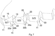
- FIG 7 is similar to in Figure 3 an embodiment is shown in which the edges (12, 13) delimiting the edge surface (22) in the circumferential direction run away from one another in the radial direction and the two edges (14, 15) delimiting the edge surface (22) in the radial direction accordingly have a different length.
- the three cutting teeth (SZ1, SZ2, SZ3) have different designs of the edge surface (22).
- the radially outer edge (14) delimiting the edge surface (22) in the radial direction is significantly shorter than the radially inner edge (15) delimiting the edge surface (22) in the radial direction.
- the edge surface (22) connects the cutting surface (11) of a cutting tooth with the transition surface (33) between two successive cutting teeth.
- each of the edge surfaces (22) shown, which connect the cutting surface (11) to the transition surface (33) between two successive cutting teeth, is curved.
- at least the edges (12, 13) and partly also the edges (14, 15) are curved.
- the edge surface (22) is divided into a first edge surface (22a) and a second edge surface (22b), which have a different curvature.
- the first edge surface (22a) is limiting in the radial direction radially inside and the second edge surface (22b) delimiting in the radial direction radially outside.
- the first edge surface (22a) is significantly larger than the second edge surface (22b).
- the second edge surface (22b) is hardly present.
- the third cutting tooth (SZ3) has a single-surface edge surface (22).
- FIG 8 is similar to in Figure 7 an embodiment is shown in which the edges (12, 13) delimiting the edge surface (22) in the circumferential direction run away from one another in the radial direction.
- the two cutting teeth (SZ4, SZ5) have similar dimensions of the edge surface (22).
- Each of the edge surfaces (22) shown, which connect the cutting surface (11) to the transition surface (33) between two successive cutting teeth, is again curved.
- the edges (12, 13) are therefore also curved.
- the edge surface (22) is the same as in the second cutting tooth (SZ2) Figure 7 divided into a first edge surface (22a) and a second edge surface (22b), which have a different curvature.
- the first edge surface (22a) is located radially on the inside, delimiting in the radial direction
- the second edge surface (22b) is located radially on the outside, delimiting in the radial direction.
- the first edge surface (22a) is significantly larger than the second edge surface (22b).
- the edge surface (22) has a single surface. However, the edge surface (22) does not reach the cutting edge (10), but ends beforehand. Thus, the curved edge surface (22) is only partially, but here largely, an edge between the cutting surface (11) and the transition surface (33) replaced. A very short edge (23) which touches the cutting edge (10) adjoins the edge surface (22) radially on the outside.
Landscapes
- Life Sciences & Earth Sciences (AREA)
- Forests & Forestry (AREA)
- Engineering & Computer Science (AREA)
- Mechanical Engineering (AREA)
- Food-Manufacturing Devices (AREA)
Applications Claiming Priority (1)
| Application Number | Priority Date | Filing Date | Title |
|---|---|---|---|
| DE102019201519.0A DE102019201519A1 (de) | 2019-02-06 | 2019-02-06 | Verzahntes Schneidmesser |
Publications (1)
| Publication Number | Publication Date |
|---|---|
| EP3693141A1 true EP3693141A1 (fr) | 2020-08-12 |
Family
ID=69526076
Family Applications (1)
| Application Number | Title | Priority Date | Filing Date |
|---|---|---|---|
| EP20155894.7A Pending EP3693141A1 (fr) | 2019-02-06 | 2020-02-06 | Lame de coupe dentée |
Country Status (2)
| Country | Link |
|---|---|
| EP (1) | EP3693141A1 (fr) |
| DE (1) | DE102019201519A1 (fr) |
Citations (5)
| Publication number | Priority date | Publication date | Assignee | Title |
|---|---|---|---|---|
| EP0548615B1 (fr) | 1991-12-24 | 1996-10-16 | Reifenhäuser, Uwe, Dipl.-Ing. | Couteau ayant une lame en forme de spirale |
| EP1627713A1 (fr) * | 2004-08-19 | 2006-02-22 | Friedr. Dick GmbH & Co.KG | Couteau pour une trancheuse pour des produits alimentaires |
| WO2014114579A2 (fr) | 2013-01-25 | 2014-07-31 | Gea Food Solutions Germany Gmbh | Lame coupante à angle de coupe variable |
| DE102017108841A1 (de) | 2016-12-16 | 2018-06-21 | Weber Maschinenbau Gmbh Breidenbach | Schneidmesser und verfahren zu dessen herstellung |
| EP3338972A1 (fr) | 2016-12-16 | 2018-06-27 | Weber Maschinenbau GmbH Breidenbach | Couteau |
Family Cites Families (4)
| Publication number | Priority date | Publication date | Assignee | Title |
|---|---|---|---|---|
| US2127861A (en) * | 1934-07-30 | 1938-08-23 | Gandriaut Lucien | Tool for cutting up into slices products having soft and hard parts |
| DE3927262A1 (de) * | 1989-08-18 | 1991-02-21 | Balke Axel | Kreis- oder bogenfoermiges maschinenmesser |
| DE10004836C1 (de) * | 2000-02-01 | 2001-10-31 | Mws Schneidwerkzeuge Gmbh & Co | Rundmesser für Allesschneider und Vorrichtung zur Herstellung der Schneidezahnung |
| US9999984B2 (en) * | 2010-01-26 | 2018-06-19 | Hyde Tools, Inc. | Circular cutting blade |
-
2019
- 2019-02-06 DE DE102019201519.0A patent/DE102019201519A1/de active Pending
-
2020
- 2020-02-06 EP EP20155894.7A patent/EP3693141A1/fr active Pending
Patent Citations (5)
| Publication number | Priority date | Publication date | Assignee | Title |
|---|---|---|---|---|
| EP0548615B1 (fr) | 1991-12-24 | 1996-10-16 | Reifenhäuser, Uwe, Dipl.-Ing. | Couteau ayant une lame en forme de spirale |
| EP1627713A1 (fr) * | 2004-08-19 | 2006-02-22 | Friedr. Dick GmbH & Co.KG | Couteau pour une trancheuse pour des produits alimentaires |
| WO2014114579A2 (fr) | 2013-01-25 | 2014-07-31 | Gea Food Solutions Germany Gmbh | Lame coupante à angle de coupe variable |
| DE102017108841A1 (de) | 2016-12-16 | 2018-06-21 | Weber Maschinenbau Gmbh Breidenbach | Schneidmesser und verfahren zu dessen herstellung |
| EP3338972A1 (fr) | 2016-12-16 | 2018-06-27 | Weber Maschinenbau GmbH Breidenbach | Couteau |
Also Published As
| Publication number | Publication date |
|---|---|
| DE102019201519A1 (de) | 2020-08-06 |
Similar Documents
| Publication | Publication Date | Title |
|---|---|---|
| EP2382856A1 (fr) | Dispositif broyeur | |
| EP2384267B1 (fr) | Couteau rotatif pour produits alimentaires | |
| DE10041810A1 (de) | Papierschredderwelle | |
| DE102004028992B4 (de) | Baumsäge | |
| EP3459699B1 (fr) | Couteau | |
| DE102019116945A1 (de) | Gegenschneide | |
| EP3693141A1 (fr) | Lame de coupe dentée | |
| EP0141042B1 (fr) | Lame de scie circulaire | |
| EP1040746A1 (fr) | Appareil pour récolter les fruits sur pied | |
| DE2310997C3 (de) | Messerkopf für Cutter | |
| EP2514531B1 (fr) | Rondelle de forme pour le traitement d'aliments | |
| EP0548615B1 (fr) | Couteau ayant une lame en forme de spirale | |
| EP3949715A1 (fr) | Lame pour couteaux rotatifs et bec cueilleur | |
| EP2813330B1 (fr) | Utilisation d'une lame dans une trancheuse pour trancher le pain | |
| EP2546034B1 (fr) | Tête porte-lame pour découpeuse de produits | |
| EP0413322B1 (fr) | Couteau circulaire ou arqué | |
| DE10108018B4 (de) | Rotationsmesser | |
| DE19610661A1 (de) | Messer für Schneidvorrichtung | |
| EP4094560A1 (fr) | Couteau, en particulier pour une barre de coupe d'une machine agricole | |
| EP4124426A2 (fr) | Lame de coupe transversale et dispositif de traitement des denrées alimentaires | |
| EP0993349B1 (fr) | Dispositif pour decouper des aretes longitudinales de bandes plates | |
| EP0803334B1 (fr) | Couteau rotatif | |
| DE102008012666A1 (de) | Kuttermesser und damit versehener Messerkopf | |
| DE202013006419U1 (de) | Messer | |
| DE102019114845A1 (de) | Slicer sowie Verfahren zu seiner Gestaltung |
Legal Events
| Date | Code | Title | Description |
|---|---|---|---|
| PUAI | Public reference made under article 153(3) epc to a published international application that has entered the european phase |
Free format text: ORIGINAL CODE: 0009012 |
|
| STAA | Information on the status of an ep patent application or granted ep patent |
Free format text: STATUS: THE APPLICATION HAS BEEN PUBLISHED |
|
| AK | Designated contracting states |
Kind code of ref document: A1 Designated state(s): AL AT BE BG CH CY CZ DE DK EE ES FI FR GB GR HR HU IE IS IT LI LT LU LV MC MK MT NL NO PL PT RO RS SE SI SK SM TR |
|
| AX | Request for extension of the european patent |
Extension state: BA ME |
|
| STAA | Information on the status of an ep patent application or granted ep patent |
Free format text: STATUS: REQUEST FOR EXAMINATION WAS MADE |
|
| 17P | Request for examination filed |
Effective date: 20210212 |
|
| RBV | Designated contracting states (corrected) |
Designated state(s): AL AT BE BG CH CY CZ DE DK EE ES FI FR GB GR HR HU IE IS IT LI LT LU LV MC MK MT NL NO PL PT RO RS SE SI SK SM TR |
|
| STAA | Information on the status of an ep patent application or granted ep patent |
Free format text: STATUS: EXAMINATION IS IN PROGRESS |
|
| 17Q | First examination report despatched |
Effective date: 20230411 |