EP3693095A1 - Paroi latérale réglable de la zone de lavage interne de la ligne de lavage de caisses équipée de jets d'eau - Google Patents
Paroi latérale réglable de la zone de lavage interne de la ligne de lavage de caisses équipée de jets d'eau Download PDFInfo
- Publication number
- EP3693095A1 EP3693095A1 EP20156606.4A EP20156606A EP3693095A1 EP 3693095 A1 EP3693095 A1 EP 3693095A1 EP 20156606 A EP20156606 A EP 20156606A EP 3693095 A1 EP3693095 A1 EP 3693095A1
- Authority
- EP
- European Patent Office
- Prior art keywords
- side wall
- adjustable side
- crates
- washing line
- wash area
- Prior art date
- Legal status (The legal status is an assumption and is not a legal conclusion. Google has not performed a legal analysis and makes no representation as to the accuracy of the status listed.)
- Pending
Links
Images


Classifications
-
- B—PERFORMING OPERATIONS; TRANSPORTING
- B08—CLEANING
- B08B—CLEANING IN GENERAL; PREVENTION OF FOULING IN GENERAL
- B08B9/00—Cleaning hollow articles by methods or apparatus specially adapted thereto
- B08B9/08—Cleaning containers, e.g. tanks
- B08B9/0861—Cleaning crates, boxes or the like
-
- B—PERFORMING OPERATIONS; TRANSPORTING
- B08—CLEANING
- B08B—CLEANING IN GENERAL; PREVENTION OF FOULING IN GENERAL
- B08B9/00—Cleaning hollow articles by methods or apparatus specially adapted thereto
- B08B9/08—Cleaning containers, e.g. tanks
- B08B9/20—Cleaning containers, e.g. tanks by using apparatus into or on to which containers, e.g. bottles, jars, cans are brought
- B08B9/28—Cleaning containers, e.g. tanks by using apparatus into or on to which containers, e.g. bottles, jars, cans are brought the apparatus cleaning by splash, spray, or jet application, with or without soaking
- B08B9/34—Arrangements of conduits or nozzles
-
- B—PERFORMING OPERATIONS; TRANSPORTING
- B08—CLEANING
- B08B—CLEANING IN GENERAL; PREVENTION OF FOULING IN GENERAL
- B08B3/00—Cleaning by methods involving the use or presence of liquid or steam
- B08B3/02—Cleaning by the force of jets or sprays
- B08B3/022—Cleaning travelling work
-
- B—PERFORMING OPERATIONS; TRANSPORTING
- B08—CLEANING
- B08B—CLEANING IN GENERAL; PREVENTION OF FOULING IN GENERAL
- B08B9/00—Cleaning hollow articles by methods or apparatus specially adapted thereto
- B08B9/08—Cleaning containers, e.g. tanks
- B08B9/0821—Handling or manipulating containers, e.g. moving or rotating containers in cleaning devices, conveying to or from cleaning devices
-
- B—PERFORMING OPERATIONS; TRANSPORTING
- B65—CONVEYING; PACKING; STORING; HANDLING THIN OR FILAMENTARY MATERIAL
- B65G—TRANSPORT OR STORAGE DEVICES, e.g. CONVEYORS FOR LOADING OR TIPPING, SHOP CONVEYOR SYSTEMS OR PNEUMATIC TUBE CONVEYORS
- B65G19/00—Conveyors comprising an impeller or a series of impellers carried by an endless traction element and arranged to move articles or materials over a supporting surface or underlying material, e.g. endless scraper conveyors
- B65G19/02—Conveyors comprising an impeller or a series of impellers carried by an endless traction element and arranged to move articles or materials over a supporting surface or underlying material, e.g. endless scraper conveyors for articles, e.g. for containers
-
- B—PERFORMING OPERATIONS; TRANSPORTING
- B65—CONVEYING; PACKING; STORING; HANDLING THIN OR FILAMENTARY MATERIAL
- B65G—TRANSPORT OR STORAGE DEVICES, e.g. CONVEYORS FOR LOADING OR TIPPING, SHOP CONVEYOR SYSTEMS OR PNEUMATIC TUBE CONVEYORS
- B65G21/00—Supporting or protective framework or housings for endless load-carriers or traction elements of belt or chain conveyors
- B65G21/20—Means incorporated in, or attached to, framework or housings for guiding load-carriers, traction elements or loads supported on moving surfaces
- B65G21/2045—Mechanical means for guiding or retaining the load on the load-carrying surface
- B65G21/2063—Mechanical means for guiding or retaining the load on the load-carrying surface comprising elements not movable in the direction of load-transport
- B65G21/2072—Laterial guidance means
Definitions
- wash area of the line is important when washing crates or boxes of various shapes and sizes.
- the wash area of the line is dimensioned for the largest crates which are guided through the washing line by means of guide rails onto which they fit closely at small distances from each other.
- the washing lines for crates or boxes are realized in several ways.
- One is to carry the crates by means of pins, wherein the pins are located on one or more chains extending longitudinally through the entire washing line, which carry the crates or boxes and pull them through the entire washing line.
- the crates are thus pulled in the direction of travel, but they are not fixed in the washing line from the sides or from above.
- Pressurized water often tosses the crate sideways and up/down in the wash area of the line, wherein it depends on the height of the wash area or wash area bounded by the guide rails, height of the crate and height of the guide pin, whether the crate is still pulled through the washing line by the pin or whether it can slip from the pin when lifted by pressurized water and jam in the wash area of the line. Washing lines realized in this way are highly liable to failure and the operation of such washing line must be under constant supervision.
- Another way of realizing the washing lines is to guide the crates through the washing line by means of fixed side plates, whereby the crate is secured in the direction of travel by solid side plates or side guide rails. While the side plates partially fix the crate from sides, the crate has the freedom to move up and down, and with the pressurized water jets, the crate is repeatedly lifted up and pressed against the conveyor or ceiling of the wash area of the line, which often results in jamming of the crate in the line or poor washing due to uneven pressure of the water jets. In addition, washing the crates from sides at the point of contact with the side plate is very limited.
- the existing washing line designs do not allow efficient attachment of crates or boxes to be washed in a fixed position, and so often they are tipped over or twisted by action of the pressurized water, resulting in either poor washing of the crate and/or jamming in the washing line, which results in a technological failure of the washer.
- Washing with a standard 20 bar high-pressure module is solved by a fixed jet system with hoses connected to the jets attached from the side to the washer frame. From above, the crates are rinsed using a shaft terminated by a jet head and a motor located on the top outside of the washer. Washing efficiency cannot be increased; higher oscillation cannot be achieved; jets do not have a proper angle to cover the whole side of the crate; moreover, there is a risk of electric shock, since the jets are motor-driven, with the motor shaft extending through the wall of the washer; and moreover, there is a risk that the simmer-ring seal ruptures and the pressurized water leaks into the motor.
- the jets on either or both sides are more distant from the crate than when washing large crates, where the jets are 100 to 150 mm from the crate, due to the fixed position of the jets from the side.
- the standard washing process is carried out in such a way that by the input conveyor the crate is transported to the washer upside down. From the inside, the crate is caught in the washer by the pins of guide chains or conveyor. The pins on the washer chain ensure that the crate does not collapse when passing through the washer, even if the crate is not closed in the locks.
- Length of a standard washer used for this calculation is 18.6 m
- Labels are attached to the shorter side of the crates. This side must therefore be subjected to the most powerful and efficient washing.
- Improvement of the quality of industrial washing of smaller or narrower crates is solved by approaching the pressure water jets/nozzles located on the internal side walls of the wash area of the washing line to the crates to be washed, wherein at least one side wall is adjustable.
- the adjustable side wall brings the pressure water jets to the same distance from the small crates as when washing large crates. This ensures the same quality of washing of the sides of both large and small crates, the width of which usually varies by 20 cm.
- the distance of water jets from the crates is crucial for the quality of washing the crate sides, as it is necessary to completely remove the stickers and labels of the exhibited goods and prepare the crate for new use.
- the pressure water is used, the force of which decreases rapidly with the distance from the object being washed.
- the emphasis is on the effective use of water pressure. Bringing the high-pressure water jets closer to the crate to be washed thus makes the entire high-pressure washing process more effective.
- the water jets can be brought directly to the crate to be washed or at any distance from the crate, which is limited only by the width of the wash area of the line.
- the force of water jets acts symmetrically and thus does not change the position of the crates by lifting up or jamming the crate in the wash area of the washer.
- Approaching the adjustableside walls to the crate to be washed also limits the lateral movements of the crate, which also increases the washing efficiency.
- At least one side wall of the interior wash area of the washing line can be positioned.
- the adjustable side wall is preferably rectangular in shape, preferably assembled from stainless steel profiles, positioned vertically in the internal wash area of the washing line, parallel to the conveyor travel axis and perpendicular to the conveyor surface.
- the side walls are getting nearer to or farther from each other according to the size of the crate.
- the wash area is narrowed or expanded depending on the size of the crates to be washed, and since the adjustable side wall is fitted with water jets, the jets are in close proximity to the washed crates, making maximum use of water pressure.
- the adjustable side wall or walls are preferably located in the internal wash area of the washing line at a height above the guide pins of the conveyor so as to be able to change the position of adjustable side walls also over the row of guide pins thereby narrowing the wash area of lines sized for large crates with a conveyor having several rows of carrier pins.
- the adjustable side wall or walls must be positionably fixed in the internal wash area of the washing line. It is fixed to a supporting frame, which may be a reinforcing frame of the internal wash area of the washing line, or a built-in supporting frame firmly attached to the reinforcing frame of the washer.
- the supporting frame ensures precise fixing and precise changing of position of the adjustable side wall or walls.
- the adjustable side wall or walls are positionably fixed to the supporting frame by means of a adjusting system.
- the adjusting system allows controlled position change of the side wall or walls.
- two opposing side walls fitted with water jets are mounted on the adjusting system.
- the adjusting system may be realized as a guide or arresting system.
- the guide system consists of a guide structure and a movable system; wherein the guide structure is preferably a rail or bar, and the movable system is preferably a counter-rail, wheel, hook.
- the side wall position changes continuously with the guide system.
- the arresting system may be a dismountable joint or a locking pin/pins with a pin hole/holes. The side wall position changes in steps with the arresting system.
- the guide system serves to continuously change the position of the adjustable side wall; it consists of a guide structure and a movable mechanism, it is located horizontally, perpendicular to the conveyor travel axis, wherein the movable mechanism is located on the adjustable side wall or walls and the guide structure is located on the supporting frame.
- the movable mechanism preferably consists of a profile mounted on a guide structure, which is preferably a rail, preferably made of C-profile, or consists of a counter-rail mounted on a rail, or consists of suspension wheels mounted on a rail, or consists of a suspension hook mounted on a rail.
- the guide system is provided with a dismountable joint at the point of contact of the rail and the mounted profile for fixing in the desired position.
- the guide structure consists of a nut and the movable mechanism consists of a threaded rod or the guide mechanism consists of at least one piston.
- the threaded rod is attached to the adjustable side wall, passes through the thread in a fixed side wall of the washer, and is preferably terminated with a loop.
- the movable mechanism preferably consists of a sliding bar connected to a adjustable side wall and extending through the side wall of the washing line, which serves as a guide structure, out of the washing line and secured by a latch in the desired operating position.
- the adjustable side wall is moved by means of a movable mechanism, preferably guided on a rail, at one horizontal height, perpendicular to the conveyor travel axis, thereby narrowing and widening the internal wash area.
- a piston is preferably used as a guide system where one of its static/movable parts is attached to the supporting frame and the other of its static/movable parts is attached to the adjustable side wall.
- the linear horizontal drive of the position change of the adjustable side wall or walls with a guide system is mechanical, pneumatic, hydraulic or electromechanical.
- the mechanical linear horizontal drive is realized manually by a sliding bar connected to the adjustable side wall and extending through the side wall out of the washing line and secured by a latch in the desired operating position.
- the bar may have a length mark corresponding to the size of the crates to be washed, or narrowing of the wash area by sliding in the adjustable side wall. The more the bar is inserted in the washing line, the more the adjustable side wall will be distant from the wall of the washing line, the more the internal wash area of the washing line will be narrowed and the smaller the crates that can be effectively washed in the washing line.
- the role of the drive can also be played by the threaded rod, which also act as a movable mechanism.
- the threaded rod on one side slidably mounted to the adjustable side wall, is led through the threaded hole in the fixed side wall out of the washer and is rotated by the loop on the other side, thereby changing the position of the adjustable side wall.
- the threaded rod is firmly attached to the adjustable side wall, is led through the hole in the fixed side wall out of the washer and there is a nut mounted on it over a sliding washer, wherein the tightening of nut against the outer wall of the washer extends the threaded rod through the wall out of the washing line, thereby moving the adjustable side wall away from the opposite side wall and expanding the internal wash area.
- the role of the pneumatic or hydraulic drive can also be played by a piston, which also acts as a guide mechanism.
- the change of position of the adjustable side wall, placed on a rail or without a rail, is semi-automatically or automatically performed by a piston.
- the piston is positioned horizontally, perpendicular to the conveyor travel axis.
- a hydraulic or air piston allows the positioning side wall to be brought closer to the opposite side wall of the internal wash area or the opposite positioning side wall, or allows the side walls to move away from each other. As the side walls move apart, the width of the wash area of the washing line is widened and wide crates can be washed. As the side walls are brought closer together, the wash area becomes narrower and narrow containers can be washed.
- the change of position of the adjustable side wall or walls with a guide system can be made for any crate width.
- the arresting system allows for a step change of position of the adjustable side wall.
- the arresting system is realized by a dismountable joint, preferably by screws and nuts, or by a locking pin/pins and a locking hole/holes.
- a plurality of steel pins is used that are located on the supporting frame horizontally, perpendicular to the conveyor travel axis, facing upward from the base.
- the adjustable side wall then has a compatible arresting system, namely a panel with a locking hole or multiple holes, where the adjustable side wall is hanged - put through the hole or holes in the positioning side wall onto a pin or pins on the supporting frame.
- an arresting system where one or more pins in a row are positioned horizontally on the adjustable side wall, perpendicular to the conveyor travel direction, wherein the pins point downwards from the base and the supporting frame has a row of holes into which the pin or pins of the adjustable side wall are hanged.
- the adjustable side wall or walls are unhooked from the pin or pins and shifted to another pin in a row or to another hole so that the width of the wash area corresponds to the width of the crates to be washed.
- the change of position of the adjustable side wall or walls with the arresting system is adjustable only for the specified widths of the wash area, depending on the location of the arresting system elements.
- the adjustable side wall or walls are properly fixed to prevent them from accidentally changing their position while the washing line is running.
- the arresting system itself provides this fixation.
- a locking system to secure the working position of the adjustable side wall.
- the locking system is preferably realized by at least one locking screw.
- the locking screw is preferably situated at the point of contact of the adjustable side wall and the supporting frame or reinforcing frame of the washer. Tightening the locking screw will lock the sliding side wall or walls in place, in the working position.
- the role of the locking system can also be played by a piston or a threaded rod, which also act as a movable mechanism and a drive.
- the adjustable side walls are fitted with jets.
- the jets can be located on the adjustable wall one at a time, solitarily, wherein a pressurized water supply hose is brought to each jet or in a jet body/bodies provided with a hollow space and a supply hose/hoses, wherein the jet body has more jets than supply hoses and the pressurized water is distributed from the supply hoses through the hollow space of the jet body to the jets.
- Adjustable side walls fitted with water jets are built into the internal wash area of existing washing lines, or the adjustable side walls are made as integrated into newly produced washing lines.
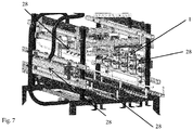
- the adjustable side wall 1 is made of stainless steel, screwed together from closed steel profiles joined at the corners with self-locking nuts, which ensure constructional accuracy for the adjusting system 6 of the linear guide.
- the adjustable side wall 1 is formed by two horizontal parallel supporting profiles 4 .
- the supporting profiles 4 are rigidly connected with supporting joints 5 , which are arranged perpendicular to the supporting profiles 4 and are screwed together with the supporting profiles 4 .
- Supporting joints 5 are connected to the base 7 of the adjusting system 6 to the shape of T or inverted L.
- the adjusting system 6 is located on the base 7 of the adjusting system 6 and consists of a locking hole, locking pins, profiled rail, suspension sliding wheel, stop of the piston 13 , hook, C-profile.
- the base 7 of the adjusting system 6 also has a locking screw 8 .
- the supporting profiles 4 are fitted with vertical brackets 9 with spacing 5 to 20 cm, which are open profiles with grooves and/or rods.
- Water jets 10 or variable parts of the adjustable side wall 1 such as skids 11 or flexible segments 12 are mounted on the brackets 9 .
- the supporting frame 2 is built-in and is made of stainless steel, screwed together from closed steel profiles joined at the corners with self-locking nuts, which ensure constructional accuracy for linear guide.
- the supporting frame 2 is formed by beams 3 perpendicular to each other, wherein the supporting frame 2 has the shape of a regular quadrilateral and can additionally be reinforced in one or the other direction by a reinforcing beam.
- the supporting frame 2 has a adjusting system 6 compatible with the adjusting system 6 located on the adjustable side wall 1 .
- the compatible adjusting system 6 on the supporting frame 2 may be a panel with holes for screwing with a hole in the base 7 of the adjusting system 6 of the sliding side wall 1 , or a panel with locking pins or locking holes to be mounted on the base 7 of the adjusting system 6 , or a profiled rail compatible with the profiled rail or suspension wheel located on the adjustable side wall 1 or a profile for attaching a hook or pin 14 of the piston 13 .
- the wash area 21 of the tunnel-like washing line 20 is reinforced by stiffeners, crossbars and the upper reinforcement strip, which are an integral part of the washing line 20 . If this is not the case, these stiffeners are installed in the wash area 21 of the washing line 20 prior to the installation of the adjustable side wall 1 .
- the installation of the adjustable side wall 1 is preceded by the installation of an adjusting frame.
- the adjusting frame is placed in the wash area 21 of the washing line 20 on the upper surface of the conveyor 22 and is centered relative to the conveyor 22 travel axis.
- the adjusting frame which is connected at the frame mounting point with screws, is designed to measure and attach the built-in adjustable side wall 1 from the 'zero point', i.e. from the conveyor 22 or from the top of the carrier pin 23 of the conveyor 22 .
- the reinforcing frame 24 serves as a supporting frame 2 .
- the adjustable side wall 1 is placed on its upper surface without fitting the brackets 9 for water jets 10 or other variable components.
- the adjustable side wall 1 is attached to the supporting frame 2 or the reinforcing frame 24 by means of a adjusting system 6 which is compatible with each other on the adjustable side wall 1 and on the supporting frame 2 .
- the adjusting system 6 is mounted horizontally on the supporting frame 2 and on the adjustable side wall 1 , perpendicular to the conveyor 22 travel axis, so as to allow the adjustable side wall 1 to move in a direction perpendicular to the travel direction of the conveyor 22 of the washing line 20 .
- the adjusting system 6 is realized by a step-shifting arresting system, i.e.
- the adjustable side wall 1 is placed so that the narrowing of the wash area 21 corresponds to the size of the crate 25 to be washed.
- the crate 25 has a width of 30 cm, the width of the wash area 21 , delimited by the adjustable side wall and the fixed side wall of the wash area 21 , was set to 35 cm by means of the adjustable side wall. Or, the adjustable side wall 1 was hanged by putting locking pins in such locking holes to achieve the desired width of the wash area 21 . Securing the adjustable side wall 1 in the selected position was realized by the arresting adjusting system 6 itself.
- the adjusting frame is removed from the washing line 20 , followed by fitting of the positioning side wall 1 with the brackets 9 and other variable components.
- the water jets 10 are connected to the brackets 9 , which are made of rods.
- the pressurized water is connected to the water jets 10 by means of hoses and the washing line 20 is started. Due to the narrowing of the wash area 21 of the washing line 20 , the crates 25 to be washed, carried by carrier pins 23 of the conveyor 22 , are better fixed - lose freedom of movement to the sides.
- the water jets 10 are as close as possible to the crates 25 to be washed and the efficiency of washing is thus stepped up.
- the adjustable side wall 1 is unhooked by removing locking pins from the locking holes and moved perpendicular to the conveyor travel axis so that the wash area 21 is expanded to wash 60 cm wide crates 25 .
- the adjustable side wall 1 was again hanged on the supporting frame 2 by means of locking pins and holes and the washing line 20 was started.
- the 60 cm wide crates 25 were washed as effectively as crates 25 only 20 cm wide.
- the wash area 21 of the tunnel-like washing line 20 is reinforced by stiffeners, crossbars and the upper reinforcement strip, which are an integral part of the washing line 20 . If this is not the case, these stiffeners are installed in the wash area 21 of the washing line 20 prior to the installation of the built-in supporting frame 2 for the adjustable side wall 1 .
- the installation of the adjustable side walls 1 is preceded by the installation of an adjusting frame.
- the adjusting frame is placed in the wash area 21 of the washing line 20 on the upper surface of the conveyor 22 and is centered relative to the conveyor 22 travel axis.
- the adjusting frame which is connected at the frame mounting point with screws, is designed to measure and attach the built-in adjustable side wall 1 or the built-in supporting frame 2 from the 'zero point', i.e. from the conveyor 22 or from the top of the carrier pin 23 of the conveyor 22 .
- the built-in supporting frame 2 is placed on its upper surface without fitting and fixed by welding to the reinforcing frame 24 of the washing line 20 .
- the supporting frame 2 is then fitted with two opposing, adjustable side walls 1 without fitting with brackets 9 and variable components.
- the adjustable side walls 1 are attached to the supporting frame 2 by means of the adjusting system 6 .
- the adjusting system 6 is a rail mounted on the supporting frame 2 and a counter-rail mounted on both positioning side walls 1 or on their bases 7 , of the adjusting system 6 .
- the rail and counter-rail are mounted horizontally on the supporting frame 2 and on the adjustable side walls 1 , perpendicular to the conveyor 22 travel axis, so as to allow the adjustable side walls 1 to move in a direction perpendicular to the travel direction of the conveyor 22 of the washing line 20 .
- Drive of the position change is provided by sliding bars which are attached to both adjustable side walls 1 and led out through the fixed side wall of the washing line 20 .
- the adjusting frame is demounted from the washing line 20 , and the positioning side walls 1 are then fitted with brackets 9 for water jets 10 and for flexible segments 12 .
- the water jets 10 are connected to the water jet 10 brackets 9 , which are made of rods.
- the flexible segments 12 are attached to the flexible segment 12 brackets 9 , which are made of open steel profiles, by means of a profile for attaching flexible segments 12 and screws with nuts. The flexible segments 12 protrude into the wash area 21 and have a pressing force acting against their deformation.
- the positioning side walls 1 are tested so that they are only moved - if there is no jamming or visible crossing of the positioning side walls 1 or the supporting frame 2 or the frame 24 of the washing line, the pressure water is connected to the water jets 10 by means of hoses.
- the adjustable side walls 1 are placed so that the narrowing of the wash area 21 corresponds to the size of the crate 25 to be washed.
- the crate 25 has a width of 40 cm, the width of the wash area 21 , delimited by both adjustable side walls 1 , is set to 50 cm, wherein the flexible segments 12 protrude into the wash area 21 and come into contact with the crate 25 , by which they are deformed.
- the adjustable side walls 1 are secured in the selected working position by means of a locking screw 8 tightened from the adjustable side wall 1 or the base of the adjusting system 6 towards the rail of the supporting frame 2 , followed by a test run of the washing line 20 .
- the crates 25 to be washed Due to the narrowing of the wash area 21 of the washing line 20 , the crates 25 to be washed, carried by carrier pins 23 of the conveyor 22 , are better fixed - lose freedom of movement to the sides.
- the water jets 10 are as close as possible to the crates 25 to be washed and the efficiency of washing is thus stepped up.
- the adjustable side wall 1 is constructed analogously to Example 2, wherein the piston 13 serves as a drive for change and at the same time as a locking system for the position of the adjustable side wall 1 .
- This piston 13 is attached from one side to a pin 14 of the piston 13 , which is welded to the flag 15 .
- the flag 15 is screwed by means of screws, washers and self-locking nuts to the supporting frame 2 or to the reinforcing frame 24 of the washing line 20 .
- the connection of the reinforcing frame 24 of the washing line 20 or the supporting frame 2 and the flag 15 is designed to hold right angles and to be self-locking when screwed together. This keeps the piston 13 in an axis perpendicular to the conveyor 22 travel.
- the piston 13 is attached to the supporting profile 4 of the adjustable side wall 1 by attachment 16 of the piston 13 , i.e. a T-shaped bracket, a pin and a fork terminal screwed onto the piston 13, wherein the T-shaped bracket is screwed to the supporting profile 4 by means of screws, washers and self-locking nuts.
- attachment 16 of the piston 13 i.e. a T-shaped bracket, a pin and a fork terminal screwed onto the piston 13, wherein the T-shaped bracket is screwed to the supporting profile 4 by means of screws, washers and self-locking nuts.
- the piston 13 is connected with a compressed air hose (6-8 bar) via the piston 13 ends.
- the hose is led through the wall of the washing line 20 to a solenoid valve.
- the piston 13 is operated by compressed air, generally controlled either manually, automatically or semi-automatically. In the case of automation, the piston 13 is controlled by an electromagnet, the control unit of the system from the switchboard, which is linked to the function of the washing line 20 . The program is then most often pre-set to a small (400 x 300 mm) or large (600 x 400 mm) crate 25 . Even the automatic piston 13 can be switched to a manual mode if the washing line 20 does not have the program. Switching to the manual mode is handled by a controller.
- the adjustable side wall 1 is placed so that the narrowing of the wash area 21 corresponds to the size of the crate 25 to be washed.
- the crate 25 has a width of 20 cm; the width of the wash area 21 , delimited by the adjustable side wall 1 and a static side wall of the wash area, is set to 25 cm.
- the adjustable side wall 1 is secured in the selected working position by action of the piston 13 and the trial start of the washing line 20 follows.
- the crates 25 to be washed Due to the narrowing of the wash area 21 of the washing line 20 , the crates 25 to be washed, carried by carrier pins 23 of the conveyor 22 , are better fixed - lose freedom of movement to the sides.
- the water jets 10 are as close as possible to the crates 25 to be washed and the efficiency of washing is thus stepped up.
- the integrated adjustable side wall 1 is made of stainless steel analogously to the standard internal wall of the washing line 20 for crates 25 , with the difference that the integrated adjustable side wall has a adjusting system 6 located on the base 7 of the adjusting system 6 .
- the adjusting system 6 may be a locking hole, locking pins, a profiled rail, a suspension sliding wheel, the stop of piston 13 , a threaded rod, a hook, a C-profile.
- the washing line 20 for crates 25 has a compatible adjusting system 6 , i.e.
- washing lines for crates and boxes, crate fixation, increased washing line efficiency Washing lines for crates and boxes, crate fixation, increased washing line efficiency.
Landscapes
- Engineering & Computer Science (AREA)
- Mechanical Engineering (AREA)
- Washing And Drying Of Tableware (AREA)
- Cleaning By Liquid Or Steam (AREA)
Applications Claiming Priority (1)
| Application Number | Priority Date | Filing Date | Title |
|---|---|---|---|
| CZ2019-74A CZ201974A3 (cs) | 2019-02-11 | 2019-02-11 | Polohovatelná boční stěna vnitřního mycího prostoru mycí linky přepravek, opatřená vodními tryskami |
Publications (1)
| Publication Number | Publication Date |
|---|---|
| EP3693095A1 true EP3693095A1 (fr) | 2020-08-12 |
Family
ID=71451219
Family Applications (1)
| Application Number | Title | Priority Date | Filing Date |
|---|---|---|---|
| EP20156606.4A Pending EP3693095A1 (fr) | 2019-02-11 | 2020-02-11 | Paroi latérale réglable de la zone de lavage interne de la ligne de lavage de caisses équipée de jets d'eau |
Country Status (2)
| Country | Link |
|---|---|
| EP (1) | EP3693095A1 (fr) |
| CZ (1) | CZ201974A3 (fr) |
Cited By (1)
| Publication number | Priority date | Publication date | Assignee | Title |
|---|---|---|---|---|
| EP4420801A1 (fr) * | 2023-02-24 | 2024-08-28 | Krones AG | Dispositif de nettoyage de récipients et procédé de fonctionnement du dispositif |
Citations (7)
| Publication number | Priority date | Publication date | Assignee | Title |
|---|---|---|---|---|
| US2425158A (en) * | 1946-01-26 | 1947-08-05 | Anthony M Masich | Adjustable guide for conveyer systems |
| DE4326164A1 (de) * | 1993-08-04 | 1995-02-09 | Guenther Zippel Maschf | Einrichtung zum Waschen und/oder Reinigen von Gebinden |
| DE9422218U1 (de) * | 1993-09-19 | 1999-07-22 | Bohrer, Ludwig, 93128 Regenstauf | Vorrichtung zum Waschen bzw. Reinigen von Flaschenkästen |
| US6199681B1 (en) * | 1998-10-30 | 2001-03-13 | Ballos, Iii Pete | Conveyor system for overcoming the elastic springback in the flaps of an empty box |
| DE20102557U1 (de) * | 2001-02-14 | 2001-10-25 | Volk & Nadenau GmbH, 44149 Dortmund | Vorrichtung zum Führen von auf Transportbahnen bewegten Gütern |
| DE10333357A1 (de) * | 2003-07-23 | 2005-02-24 | Platz Reinigungssysteme Gmbh | Niederhaltersystem mit integrierter Seitenführung für Behälter und Kistendurch laufwaschanlage |
| AT412708B (de) * | 2002-07-18 | 2005-06-27 | Mtv Foerder U Reinigungssystem | Führungssystem und düsensystem einer waschanlage |
Family Cites Families (3)
| Publication number | Priority date | Publication date | Assignee | Title |
|---|---|---|---|---|
| DE102004058150C5 (de) * | 2004-11-22 | 2014-04-17 | Ludwig Bohrer | Vorrichtung zum Waschen bzw. Reinigen von Behältern, insbesondere Flaschenkästen |
| DE102007011957B4 (de) * | 2007-03-09 | 2012-04-26 | Ludwig Bohrer Maschinenbau Gmbh | Flaschenkastenreiniger |
| CN205020473U (zh) * | 2015-08-26 | 2016-02-10 | 厦门申颖科技有限公司 | 一种容器自动清洗烘干机 |
-
2019
- 2019-02-11 CZ CZ2019-74A patent/CZ201974A3/cs unknown
-
2020
- 2020-02-11 EP EP20156606.4A patent/EP3693095A1/fr active Pending
Patent Citations (7)
| Publication number | Priority date | Publication date | Assignee | Title |
|---|---|---|---|---|
| US2425158A (en) * | 1946-01-26 | 1947-08-05 | Anthony M Masich | Adjustable guide for conveyer systems |
| DE4326164A1 (de) * | 1993-08-04 | 1995-02-09 | Guenther Zippel Maschf | Einrichtung zum Waschen und/oder Reinigen von Gebinden |
| DE9422218U1 (de) * | 1993-09-19 | 1999-07-22 | Bohrer, Ludwig, 93128 Regenstauf | Vorrichtung zum Waschen bzw. Reinigen von Flaschenkästen |
| US6199681B1 (en) * | 1998-10-30 | 2001-03-13 | Ballos, Iii Pete | Conveyor system for overcoming the elastic springback in the flaps of an empty box |
| DE20102557U1 (de) * | 2001-02-14 | 2001-10-25 | Volk & Nadenau GmbH, 44149 Dortmund | Vorrichtung zum Führen von auf Transportbahnen bewegten Gütern |
| AT412708B (de) * | 2002-07-18 | 2005-06-27 | Mtv Foerder U Reinigungssystem | Führungssystem und düsensystem einer waschanlage |
| DE10333357A1 (de) * | 2003-07-23 | 2005-02-24 | Platz Reinigungssysteme Gmbh | Niederhaltersystem mit integrierter Seitenführung für Behälter und Kistendurch laufwaschanlage |
Cited By (2)
| Publication number | Priority date | Publication date | Assignee | Title |
|---|---|---|---|---|
| EP4420801A1 (fr) * | 2023-02-24 | 2024-08-28 | Krones AG | Dispositif de nettoyage de récipients et procédé de fonctionnement du dispositif |
| DE102023104619A1 (de) | 2023-02-24 | 2024-08-29 | Krones Aktiengesellschaft | Vorrichtung zum Reinigen von Behältnissen und Verfahren zum Betreiben der Vorrichtung |
Also Published As
| Publication number | Publication date |
|---|---|
| CZ308403B6 (cs) | 2020-07-29 |
| CZ201974A3 (cs) | 2020-07-29 |
Similar Documents
| Publication | Publication Date | Title |
|---|---|---|
| EP3693095A1 (fr) | Paroi latérale réglable de la zone de lavage interne de la ligne de lavage de caisses équipée de jets d'eau | |
| US11388988B2 (en) | Lifting table and a method of operating and cleaning a lifting table | |
| US20080000508A1 (en) | Apparatus for washing wheels and lower parts of vehicles | |
| KR101941140B1 (ko) | 고압 세척기 | |
| CN105905633A (zh) | 一种甘蔗卸车清洗平台 | |
| US7467994B2 (en) | Variable size carcass contaminant removal | |
| US5067857A (en) | Apparatus for diverting the movement of cylindrical bodies | |
| US20080053789A1 (en) | Handrail for a travelator, escalator or moving ramp and methods for mounting a handrail belt on a handrail and removing from a handrail | |
| US11090701B2 (en) | Bin cleaning systems and methods of use | |
| EP3693094A1 (fr) | Système de caisse de fixation à pression intégrée conçu pour des lignes de lavage de caisses | |
| EP3936240A1 (fr) | Convoyeur à chaîne à broches d'arrêt pour lignes de lavage de caisses | |
| CN207952086U (zh) | 一种压滤机自动清洗机 | |
| JP4053777B2 (ja) | 液体塗布装置における塗布ヘッドのメンテナンス機構 | |
| US3199783A (en) | Automobile positioning device | |
| JP4428204B2 (ja) | 搬送装置 | |
| CN208932305U (zh) | 折叠式过道输送机 | |
| KR102387045B1 (ko) | 2단 가변높이 구조를 가진 크린룸용 조립식 시스템 천장 | |
| KR101746274B1 (ko) | 고정장치가 구비된 박스 고압세척기 | |
| US5451028A (en) | Supporting frame for textile machine operating devices with "C" shaped and rectilinear tubular components | |
| JP4270513B2 (ja) | 除塵機 | |
| KR20100003462A (ko) | 빔 이동장치 | |
| CN108928599A (zh) | 折叠式过道输送机 | |
| CN211989910U (zh) | 一种建筑机械用可移动清洗装置 | |
| CN105444951A (zh) | 一种轮胎静平衡检测用定中装置 | |
| KR102618365B1 (ko) | 진공펌프 게이트밸브용 출납유닛 구조 |
Legal Events
| Date | Code | Title | Description |
|---|---|---|---|
| PUAI | Public reference made under article 153(3) epc to a published international application that has entered the european phase |
Free format text: ORIGINAL CODE: 0009012 |
|
| STAA | Information on the status of an ep patent application or granted ep patent |
Free format text: STATUS: REQUEST FOR EXAMINATION WAS MADE |
|
| 17P | Request for examination filed |
Effective date: 20200310 |
|
| AK | Designated contracting states |
Kind code of ref document: A1 Designated state(s): AL AT BE BG CH CY CZ DE DK EE ES FI FR GB GR HR HU IE IS IT LI LT LU LV MC MK MT NL NO PL PT RO RS SE SI SK SM TR |
|
| AX | Request for extension of the european patent |
Extension state: BA ME |
|
| STAA | Information on the status of an ep patent application or granted ep patent |
Free format text: STATUS: EXAMINATION IS IN PROGRESS |
|
| 17Q | First examination report despatched |
Effective date: 20221116 |