EP3692881A1 - Handgeführter staubsauger - Google Patents
Handgeführter staubsauger Download PDFInfo
- Publication number
- EP3692881A1 EP3692881A1 EP20153014.4A EP20153014A EP3692881A1 EP 3692881 A1 EP3692881 A1 EP 3692881A1 EP 20153014 A EP20153014 A EP 20153014A EP 3692881 A1 EP3692881 A1 EP 3692881A1
- Authority
- EP
- European Patent Office
- Prior art keywords
- vacuum cleaner
- floor nozzle
- suction
- axis
- configuration
- Prior art date
- Legal status (The legal status is an assumption and is not a legal conclusion. Google has not performed a legal analysis and makes no representation as to the accuracy of the status listed.)
- Granted
Links
Images

Classifications
-
- A—HUMAN NECESSITIES
- A47—FURNITURE; DOMESTIC ARTICLES OR APPLIANCES; COFFEE MILLS; SPICE MILLS; SUCTION CLEANERS IN GENERAL
- A47L—DOMESTIC WASHING OR CLEANING; SUCTION CLEANERS IN GENERAL
- A47L5/00—Structural features of suction cleaners
- A47L5/12—Structural features of suction cleaners with power-driven air-pumps or air-compressors, e.g. driven by motor vehicle engine vacuum
- A47L5/22—Structural features of suction cleaners with power-driven air-pumps or air-compressors, e.g. driven by motor vehicle engine vacuum with rotary fans
- A47L5/24—Hand-supported suction cleaners
-
- A—HUMAN NECESSITIES
- A47—FURNITURE; DOMESTIC ARTICLES OR APPLIANCES; COFFEE MILLS; SPICE MILLS; SUCTION CLEANERS IN GENERAL
- A47L—DOMESTIC WASHING OR CLEANING; SUCTION CLEANERS IN GENERAL
- A47L5/00—Structural features of suction cleaners
- A47L5/12—Structural features of suction cleaners with power-driven air-pumps or air-compressors, e.g. driven by motor vehicle engine vacuum
- A47L5/22—Structural features of suction cleaners with power-driven air-pumps or air-compressors, e.g. driven by motor vehicle engine vacuum with rotary fans
- A47L5/28—Suction cleaners with handles and nozzles fixed on the casings, e.g. wheeled suction cleaners with steering handle
-
- A—HUMAN NECESSITIES
- A47—FURNITURE; DOMESTIC ARTICLES OR APPLIANCES; COFFEE MILLS; SPICE MILLS; SUCTION CLEANERS IN GENERAL
- A47L—DOMESTIC WASHING OR CLEANING; SUCTION CLEANERS IN GENERAL
- A47L9/00—Details or accessories of suction cleaners, e.g. mechanical means for controlling the suction or for effecting pulsating action; Storing devices specially adapted to suction cleaners or parts thereof; Carrying-vehicles specially adapted for suction cleaners
- A47L9/0009—Storing devices ; Supports, stands or holders
- A47L9/0054—Stands or the like for temporary interruption of work
Definitions
- the invention relates to a hand-held vacuum cleaner which, for the sake of simplicity, is referred to below as a vacuum cleaner.
- the invention relates to a vacuum cleaner with a handle, a suction tube, a floor nozzle and a separation unit which has a drive unit and a suction material container in order to suck suction material through the floor nozzle into the suction material container.
- a hand-held vacuum cleaner is also referred to as a stick vacuum cleaner, a stick or a hand-held vacuum cleaner.
- During operation it only has contact with the absorbent surface through the floor nozzle and is guided or maneuvered by a user using the handle.
- a vacuum cleaner in which the handle, the suction tube, the floor nozzle and the separation unit can be connected to one another in a first configuration and in a second configuration.
- the suction tube is arranged between the separation unit and the handle.
- the suction pipe is arranged between the floor nozzle and the separation unit in such a way that the suction material that is sucked in passes the suction pipe on the way from the floor nozzle into the suction material container.
- a vacuum cleaner there are various components such as e.g. the drive unit and the suction material container different mass accumulations.
- these mass accumulations can trigger an imbalance if the centers of the masses do not lie on an effective axis about which the vacuum cleaner can be rotated during operation.
- distances from the centers of the masses to the effective axis are important for maneuverability of the vacuum cleaner, because a torque to be introduced depends on them. The greater the torque to be introduced, the more force a user of the vacuum cleaner has to apply to generate the torque. This is disadvantageous and can quickly lead to arm fatigue with which the user is maneuvering or guiding the vacuum cleaner.
- vacuum cleaners are known in the prior art that can stand independently in one position, the so-called “self-stand”. This is advantageous if the user of the vacuum cleaner takes a suction break and wants to leave the vacuum cleaner standing for a short or long period and quickly have it ready for use again. In the standing position, however, the vacuum cleaner is not sufficiently secure against tipping over.
- the invention therefore poses the problem of providing a hand-held vacuum cleaner which enables a self-stand in a first configuration and in a second configuration Configuration prevents a self-stand and also has optimal maneuverability in both configurations.
- the advantages that can be achieved with the invention, in addition to optimized maneuverability, consist in the fact that, with a given configuration, a standing position can be provided in which the vacuum cleaner is stable and does not have to be held by the user.
- the vacuum cleaner is also designed to be kinematically optimal.
- the arrangement of the vacuum cleaner's center of gravity below the effective axis has a positive effect on maneuverability.
- a movement for steering the vacuum cleaner by turning it around the active axis can be carried out with very little effort.
- the vacuum cleaner has a stable, straight-ahead driving position. Similar to power steering, it can pull itself straight when cornering. This makes the vacuum cleaner user-friendly.
- the maneuverability of the vacuum cleaner appears more stable and less hectic.
- a standing position can be provided in a first configuration in which the vacuum cleaner stands automatically and securely in place.
- a vacuum cleaner center of gravity is located below an active axis during normal operation, which runs through a pivot point of the floor nozzle and a gripping point of the handle.
- the vacuum cleaner By arranging the vacuum cleaner's center of gravity below the effective axis, a negative moment of inertia is avoided. This provides the user with stable handling that does not appear hectic and does not tend, or at least little, to oversteer. As a result, a suction process when the vacuum cleaner is in operation is relatively less strenuous for the user, so that the user can vacuum with the vacuum cleaner for longer without showing signs of fatigue in the arm.
- the vacuum cleaner looks aesthetic in both configurations.
- the self-stand function can be implemented in the first configuration without additional components such as magnets or the like, which reduces the production effort of the vacuum cleaner. It is also easy to set up in both configurations.
- the first configuration is referred to as the lower configuration, the background of the term “lower” being that the separating unit is arranged in the lower area of the vacuum cleaner during operation.
- suctioned material does not pass through the suction tube. Rather, the sucked up suction material reaches the separation unit directly from the floor nozzle.
- the second configuration is referred to below as the upper configuration, the background to the designation "upper” being that the separating unit is arranged in the upper area of the vacuum cleaner when it is operated appropriately.
- the lower area is arranged closer to the ground than the upper area when handled appropriately.
- Position and directional information refer to the proper handling of the vacuum cleaner, i.e. his working position.
- the vacuum cleaner can be handled more flexibly than in the lower configuration.
- the self-stand of the vacuum cleaner can be used in the lower configuration.
- the separation unit has the suction material container and the drive unit.
- the suction material container is designed to catch and collect liquid and / or preferably solid suction material such as dirt, dust and the like that are sucked up during operation. It also has a device body in which the drive unit is integrated.
- the suction material container and the device body are preferably detachably connected to one another.
- the device body is preferably arranged in the lower and the upper configuration in such a way that it is arranged closer to the surface to be vacuumed in the working positions than the suction material container.
- the floor nozzle preferably has a joint, more preferably a swivel joint.
- the floor nozzle preferably has a connection section on the swivel joint, with which the suction pipe or the separation unit can be detachably connected via a connection piece, if necessary.
- the active axis runs essentially along a suction pipe axis along which the suction pipe runs. This also ensures excellent maneuverability of the vacuum cleaner.
- the separation unit is preferably releasably connected to the handle in the upper configuration. As a result, the distance between the masses of the separation unit components and the effective axis is relatively small. By a steering movement by turning around the effective axis the masses close to the axis can be moved by the user with very little effort.
- the vacuum cleaner preferably has a floor nozzle axis which runs parallel in a joint of the floor nozzle and intersects the pivot point of the floor nozzle, the suction tube running along the suction tube axis and the floor nozzle axis and the suction tube axis spanning an axis angle between 5 ° and 35 °.
- the axis angle is preferably between 10 ° and 30 °.
- the axis angle is even more preferably between 15 ° and 25 °. This creates a kink in the vacuum cleaner.
- the kinked arrangement results in a good distribution of mass for the standing position, in which the vacuum cleaner can stand independently.
- the vacuum cleaner is designed to be very stable in the standing position.
- the vacuum cleaner also has an accumulator which is designed to supply the drive unit with power.
- the accumulator is preferably arranged on the separation unit. More preferably, the accumulator is arranged in the lower and the upper configuration in each case such that it is arranged at one end of the device body which is opposite the end at which the suction material container is arranged.
- the vacuum cleaner center of gravity depends on a mass of the separation unit, containing a mass of the suction material container, a mass of the drive unit, a mass of a device body containing the drive unit, and optionally a mass of the accumulator, all masses being at least 70%, preferably at least 80%, more preferably at least 90% below the effective axis, based on a working position of the vacuum cleaner. This ensures that the vacuum cleaner's center of gravity is below the effective axis.
- the vacuum cleaner is able to stand independently in a standing position in the lower configuration.
- the vacuum cleaner is more preferably designed to stand on a surface that is up to 10 ° inclined to a plane.
- the vacuum cleaner does not require any further mechanics or electrics that differentiate the two configurations and then allow the lower configuration to stand independently. Rather, this is only guaranteed by the arrangement of the axes and the vacuum cleaner components with the vacuum cleaner center of gravity below the effective axis. This is a very economical and trouble-free solution for the vacuum cleaner.
- the suction tube and the separation unit are arranged in the standing position perpendicular or essentially perpendicular to a substrate on which the floor nozzle is arranged.
- the stable and stable standing position is still guaranteed.
- the user can intuitively recognize the standing position.
- the suction pipe is arranged perpendicular to the ground when its suction pipe axis is perpendicular to the ground.
- the separation unit is arranged perpendicular to the substrate if a longitudinal extension is arranged perpendicular to it.
- the vacuum cleaner's center of gravity is preferably located between a delimitation axis that runs vertically through the pivot point of the floor nozzle and a further delimitation axis that runs vertically through a standing point that represents a fixing connection. This also ensures that the standing position cannot tip over.
- the vacuum cleaner can preferably be tilted at least on a flat / horizontal surface without a standing position and / or in any position it can occupy at an angle to a surface to be vacuumed. This ensures that the user is not looking for a standing position in the upper configuration, but intuitively recognizes that there is no standing position in the upper configuration.
- the vacuum cleaner is preferably designed not to achieve a stable standing state. Rather, the vacuum cleaner is designed to be tiltable in any position during handling.
- the vacuum cleaner center of gravity or the masses influencing it preferably have a relatively large distance from the delimitation axis and from the further delimitation axis. This ensures that it is not suggested to the user that there could be a standing position in the upper configuration. Rather, in the upper configuration, the vacuum cleaner does not have a position that the user could consider stable enough for independent standing.
- the vacuum cleaner is designed as a cyclone vacuum cleaner.
- cyclone vacuum cleaner is to be understood as meaning a vacuum cleaner which is bagless and whirls and any turbulence are generated in an air flow entering the vacuum cleaner, whereby the suction material such as dust particles are pressed in a predetermined direction and separated due to centrifugal force.
- bagless means that the suction material in the vacuum cleaner is collected directly in the suction material container without a bag or similar replaceable filter medium for receiving suction material being arranged in it, so that the user has to empty the suction material from the suction material container does not remove a bag or the like from the suction material container.
- the vacuum cleaner can, however, have one or more filter media which prevent suction material from reaching the drive unit arranged in the device body.
- a vacuum cleaner is preferably designed to be able to be operated without a suction tube in a third configuration.
- the floor nozzle is releasably connected to the separation unit and the separation unit is releasably connected to the handle.
- automatic steering centering is achieved by means of the vacuum cleaner center of gravity below the effective axis.
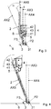
- Fig. 1 shows a side view of a vacuum cleaner according to the invention in the lower configuration in a working position.
- the hand-held vacuum cleaner has a handle 1 with which a user (not shown) can grip and maneuver the vacuum cleaner.
- the vacuum cleaner has a suction tube 2, a floor nozzle 3 and a separation unit 4.
- the separation unit 4 has a device body 41, a drive unit 43 and a suction material container 42.
- the drive unit 43 is integrated in the device body 41.
- the drive unit 43 is designed to generate a suction air flow (not shown) during operation in order to suck suction material through the floor nozzle 3 into the suction material container 42.
- the vacuum cleaner has an accumulator 5, which is designed to supply the drive unit 43 with energy during operation.
- the vacuum cleaner is arranged on a surface 6 to be vacuumed, so that the floor nozzle 3 contacts it and the user can maneuver it well.
- the floor nozzle 3 and the accumulator 5 are each detachably connected to the device body 41 at its lower end, while it is detachably connected to one end of the suction tube 2 and the suction material container 42 at its upper end opposite the lower end.
- the suction tube 2 is also releasably attached to the suction material container 42.
- the handle 1 is detachably connected to the suction tube 2.
- the vacuum cleaner has a vacuum cleaner center of gravity (not shown), which is located below an effective axis AX1 during operational handling.
- the effective axis AX1 runs through a pivot point P2 of the floor nozzle 3 and a gripping point P1 of the handle 1.
- the vacuum cleaner center of gravity depends on a mass of the suction material container 42, a mass of the drive unit 43, a mass of the device body 41 and a mass of the accumulator 5.
- a floor nozzle axis AX2 runs parallel to the joint connector 31 of the floor nozzle 3 and intersects the pivot point P2 of the floor nozzle 3, while the suction pipe 2 runs along a suction pipe axis AX5.
- the bottom nozzle axis AX2 and the suction pipe axis AX5 span an axis angle ⁇ which is between 5 ° and 35 °.
- Fig. 2 shows a further side view of the in Fig. 1 vacuum cleaner shown in the upper configuration in a working position.
- the suction pipe 2 is arranged between the floor nozzle 3 and the separation unit 4 in such a way that the suction material (not shown) passes through the suction pipe 2 on the way from the floor nozzle 3 into the suction material container 42.
- the floor nozzle 3 is detachably connected to one end of the suction tube 2, while the end of the suction tube 2 opposite this end is detachably connected to one end of the device body 41.
- the accumulator 5 is detachably connected to the device body 41.
- the suction material container 42 is releasably connected to the end of the device body 41 which is opposite its end, with which it is connected to the suction tube 2.
- the handle 1 is detachably connected to the device body 41 and the suction material container 42. In the working position, the vacuum cleaner is arranged on a surface 6 to be vacuumed, so that the floor nozzle 3 contacts it and the user can maneuver it well.
- the vacuum cleaner center of gravity S which is shown in dashed lines, is located below the active axis AX1, which runs through the pivot point P2 of the floor nozzle 3 and the gripping point P1 of the handle 1, when it is handled appropriately.
- the vacuum cleaner center of gravity S depends on the mass of the suction material container 42, the mass of the drive unit 43, the mass of the device body 41 and the mass of the accumulator 5.
- the masses of the accumulator 5 and the separation unit 4 are located is at least predominantly below the effective axis AX1, based on the shown working position of the vacuum cleaner.
- Fig. 3 shows a further side view of the in Fig. 1 vacuum cleaner shown in the lower configuration in a standing position.
- the vacuum cleaner is able to stand independently in a standing position on the base 6.
- the suction pipe 2 and the associated suction pipe axis AX5 and the separation unit 4 with its longest extension direction are arranged perpendicularly or essentially perpendicularly to the substrate 6 in the standing position.
- the masses of the accumulator 5 and the separation unit 4 or their center points are located between a limiting axis AX3 and a further limiting axis AX4.
- the limiting axis AX3 runs perpendicularly through the pivot point P2 of the floor nozzle 3.
- the further limiting axis AX4 runs perpendicularly through a standing point P3, which represents a fixing connection.
- the vacuum cleaner center of gravity S shown in broken lines, is predominantly located between the limiting axis AX3 and the further limiting axis AX4.
- Fig. 4 shows a further side view of the in Fig. 3 shown vacuum cleaner in the upper configuration in a supposed standing position.
- the separation unit 4 In the supposed standing position, the separation unit 4 is arranged essentially perpendicular to the substrate 6.
- the masses of the separation unit 4 and the accumulator 5 lie outside the delimitation axis AX3 and the further delimitation axis AX4.
- a user (not shown) operates the vacuum cleaner in the in Fig. 4 arranges the supposed standing position shown, it falls in a direction of fall indicated by an arrow until it comes to rest on the ground 6.
- the vacuum cleaner is in the upper configuration without a standing position.
Landscapes
- Engineering & Computer Science (AREA)
- Mechanical Engineering (AREA)
- Electric Vacuum Cleaner (AREA)
- Nozzles For Electric Vacuum Cleaners (AREA)
- Electric Suction Cleaners (AREA)
Abstract
Description
- Die Erfindung betrifft einen handgeführten Staubsauger, der nachfolgend der Einfachheit halber als Staubsauger bezeichnet wird. Insbesondere betrifft die Erfindung einen Staubsauger mit einem Handgriff, einem Saugrohr, einer Bodendüse und einer Abscheideeinheit, welche ein Antriebsaggregat und einen Sauggutbehälter aufweist, um Sauggut durch die Bodendüse in den Sauggutbehälter zu saugen. Ein solch handgeführter Staubsauger wird auch als Stabstaubsauger, als Stick oder als Handstaubsauger bezeichnet. Er hat bei Betrieb nur durch die Bodendüse Kontakt zum saugenden Untergrund und wird von einem Nutzer mittels des Handgriffs geführt bzw. manövriert.
- Aus der
DE 10 2016 105 475 A1 ist ein Staubsauger bekannt, bei dem der Handgriff, das Saugrohr, die Bodendüse und die Abscheideeinheit in einer ersten Konfiguration und in einer zweiten Konfiguration miteinander verbindbar sind. In der ersten Konfiguration ist das Saugrohr zwischen der Abscheideeinheit und dem Handgriff angeordnet. In der zweiten Konfiguration ist das Saugrohr derart zwischen der Bodendüse und der Abscheideeinheit angeordnet, dass das angesaugte Sauggut auf dem Weg von der Bodendüse in den Sauggutbehälter das Saugrohr passiert. - Bei einem derartigen Staubsauger gibt es durch verschiedene Bauteile wie z.B. dem Antriebsaggregat und dem Sauggutbehälter verschiedene Massenanhäufungen. Diese Massenanhäufungen können bei Betrieb, wenn der Staubsauger bewegt wird, ein Ungleichgewicht auslösen, wenn Mittelpunkte der Massen nicht auf einer Wirkachse liegen, um die der Staubsauger bei Betrieb drehbar ist. Weiterhin sind Abstände von den Mittelpunkten der Massen zur Wirkachse für eine Manövrierbarkeit des Staubsaugers wichtig, weil ein einzuleitendes Drehmoment davon abhängig ist. Je größer das einzuleitende Drehmoment ist, desto mehr Kraft muss ein Nutzer des Staubsaugers aufwenden um das Drehmoment zu erzeugen. Dies ist unvorteilhaft und kann schnell zu einer Ermüdung eines Arms führen, mit dem der Nutzer den Staubsauger manövriert bzw. führt.
- Darüber hinaus sind im Stand der Technik sind Staubsauger bekannt, die in einer Position selbstständig stehen können, dem sogenannten "Selfstand". Dies ist vorteilhaft, wenn der Nutzer des Staubsaugers eine Saugpause macht und den Staubsauger kurz- oder langzeitig stehen lassen und schnell wieder einsatzbereit haben will. In der Stehposition steht der Staubsauger jedoch nicht in ausreichendem Maße kippsicher.
- Der Erfindung stellt sich somit das Problem, einen handgeführten Staubsauger zur Verfügung zu stellen, der in einer ersten Konfiguration einen Selfstand ermöglicht, in einer zweiten Konfiguration einen Selfstand verhindert und zusätzlich in beiden Konfigurationen eine optimale Manövrierbarkeit aufweist.
- Erfindungsgemäß wird dieses Problem durch einen handgeführten Staubsauger mit den Merkmalen des Patentanspruchs 1 gelöst. Vorteilhafte Ausgestaltungen und Weiterbildungen der Erfindung ergeben sich aus den nachfolgenden Unteransprüchen.
- Die mit der Erfindung erreichbaren Vorteile bestehen neben einer optimierten Manövrierbarkeit darin, dass bei einer vorgegebenen Konfiguration eine Stehposition bereitgestellt werden kann, in der der Staubsauger kippsicher steht, ohne vom Nutzer gehalten werden zu müssen. Der Staubsauger ist zudem kinematisch optimal ausgelegt.
- Die Anordnung des Staubsauger-Schwerpunkts unterhalb der Wirkachse wirkt sich positiv auf die Manövrierbarkeit aus. Eine Bewegung zum Lenken des Staubsaugers mittels Drehen um die Wirkachse kann mit einem sehr geringen Kraftaufwand durchgeführt werden. Zudem gibt es eine leichte Rückstellkraft in eine gerade Saugfahrrichtung, wenn der Staubsauger in diese Richtung bewegt wird. Der Staubsauger hat eine stabile geradeaus gerichtete Fahrposition. Er kann sich ähnlich wie bei einer Servolenkung bei einer Kurve gerade ziehen. Dadurch ist der Staubsauger bedienerfreundlich. Zudem wirkt die Manövrierbarkeit des Staubsaugers stabiler und weniger hektisch. Gleichzeitig kann durch die Anordnung des Staubsauger-Schwerpunkts und die dadurch erzielte Masseverteilung eine Stehposition in einer ersten Konfiguration bereitgestellt werden, in der der Staubsauger selbständig kippsicher steht.
- Erfindungsgemäß ist vorgesehen, dass ein Staubsauger-Schwerpunkt sich bei betriebsgemäßer Handhabung unterhalb einer Wirkachse befindet, welche durch einen Drehpunkt der Bodendüse und einem Greifpunkt des Handgriffs verläuft.
- Durch die Anordnung des Staubsauger-Schwerpunktes unterhalb der Wirkachse, wird ein negatives Trägheitsmoment vermieden. Dadurch wird dem Nutzer eine stabile Handhabung bereitgestellt, die nicht hektisch wirkt und nicht oder zumindest wenig zum Übersteuern neigt. Dadurch ist ein Saugvorgang bei Betrieb des Staubsaugers für den Nutzer relativ wenig kraftraubend, so dass der Nutzer länger ohne Ermüdungserscheinungen im Arm mit dem Staubsauger saugen kann. Zudem sieht der Staubsauger in beiden Konfigurationen ästhetisch aus. Zudem lässt sich die Selfstand-Funktion in der ersten Konfiguration ohne zusätzliche Bauteile wie zum Beispiel Magneten oder ähnliches realisieren, wodurch der Fertigungsaufwand des Staubsaugers reduziert wird. Er ist zudem in beiden Konfigurationen einfach aufbaubar.
- Nachstehend wird die erste Konfiguration als untere Konfiguration bezeichnet, wobei der Hintergrund der Bezeichnung "untere" ist, dass die Abscheideeinheit bei betriebsgemäßer Handhabung im unteren Bereich des Staubsaugers angeordnet ist. In der unteren Konfiguration passiert aufgesaugtes Sauggut das Saugrohr nicht. Vielmehr gelangt das aufgesaugte Sauggut von der Bodendüse direkt in die Abscheideeinheit. Die zweite Konfiguration wird nachstehend als obere Konfiguration bezeichnet, wobei der Hintergrund der Bezeichnung "obere" ist, dass die Abscheideeinheit bei betriebsgemäßer Handhabung im oberen Bereich des Staubsaugers angeordnet ist. Der untere Bereich ist bei betriebsgemäßer Handhabung untergrundnäher angeordnet als der obere Bereich. Positions- und Richtungsangaben beziehen sich auf die betriebsgemäße Handhabung des Staubsaugers d.h. seine Arbeitsposition. In der oberen Konfiguration ist der Staubsauger flexibler handhabbar als in der unteren Konfiguration. Dagegen kann in der unteren Konfiguration der Selfstand des Staubsaugers genutzt werden.
- Die Abscheideeinheit weist den Sauggutbehälter und das Antriebsaggregat auf. Der Sauggutbehälter ist ausgelegt, bei Betrieb aufgesaugtes flüssiges und/oder bevorzugt festes Sauggut wie Schmutz, Staub und dgl. aufzufangen und zu sammeln. Weiterhin weist sie einen Gerätekorpus auf, in den das Antriebsaggregat intergiert ist. Der Sauggutbehälter und der Gerätekorpus sind bevorzugt lösbar miteinander verbunden. Bevorzugt ist der Gerätekorpus in der unteren und der oberen Konfiguration jeweils derart angeordnet, dass er in den Arbeitspositionen näher zum zu saugenden Untergrund angeordnet ist als der Sauggutbehälter. Bei Greifen bei dem Greifpunkt durch einen Nutzer wird ein Drehmoment eingeleitet, bei dem der Staubsauger-Schwerpunkt um die Wirkachse gedreht wird. Dadurch, dass der Staubsauger-Schwerpunkt achsnah ausgebildet ist, d.h. er weist einen relativ kleinen Abstand zur Wirkachse auf, ist das eingeleitete Drehmoment relativ klein. Dadurch ist eine relativ kleine Kraft des Nutzers nötig, um den Staubsauger zu drehen. Der Staubsauger weist daher die optimierte Manövrierbarkeit auf.
- Die Bodendüse weist bevorzugt ein Gelenk bevorzugter ein Drehgelenk auf. Bevorzugt weist die Bodendüse am Drehgelenk einen Verbindungsabschnitt auf, mit dem das Saugrohr oder die Abscheideeinheit ggf. über ein Verbindungsstück lösbar verbunden werden können.
- In einer bevorzugten Ausführungsform verläuft in der oberen Konfiguration die Wirkachse im Wesentlichen entlang einer Saugrohrachse, entlang welcher das Saugrohr verläuft. Dadurch wird weiterhin eine hervorragende Manövrierbarkeit des Staubsaugers gewährleistet. Die Abscheideeinheit ist bevorzugt in der oberen Konfiguration mit dem Handgriff lösbar verbunden. Dadurch ist ein Abstand der Massen der Abscheideeinheit-Bauteile zur Wirkachse relativ gering. Durch eine Lenkbewegung mittels Drehen um die Wirkachse können die achsnahen Massen vom Nutzer mit einem sehr geringen Kraftaufwand bewegt werden.
- Bevorzugt weist der Staubsauger in der unteren Konfiguration eine Bodendüsenachse auf, welche parallel in einem Gelenkstutzen der Bodendüse verläuft und den Drehpunkt der Bodendüse schneidet, wobei das Saugrohr entlang der Saugrohrachse verläuft und wobei die Bodendüsenachse und die Saugrohrachse einen Achsenwinkel aufspannen, welcher zwischen 5° und 35° liegt. Bevorzugt liegt der Achsenwinkel zwischen 10° und 30°. Noch bevorzugter liegt der Achsenwinkel zwischen 15° und 25°. Dadurch wird ein Knick in dem Staubsauger erzeugt. Durch die geknickte Anordnung wird eine gute Massenverteilung für die Stehposition erreicht, in der der Staubsauger selbständig stehen kann. Der Staubsauger ist in der Stehposition sehr kippsicher ausgestaltet.
- In einer bevorzugten Ausführungsform weist der Staubsauger weiterhin einen Akkumulator auf, der ausgebildet ist, das Antriebsaggregat mit Strom zu versorgen. Der Akkumulator ist bevorzugt an der Abscheideeinheit angeordnet. Bevorzugter ist Akkumulator in der unteren und der oberen Konfiguration jeweils derart angeordnet, dass er an einem Ende des Gerätekorpus angeordnet ist, das dem Ende gegenüberliegt, an dem der Sauggutbehälter angeordnet ist.
- Bevorzugt hängt der Staubsauger-Schwerpunkt von einer Masse der Abscheideeinheit, enthaltend eine Masse des Sauggutbehälters, eine Masse des Antriebsaggregats, einer Masse eines das Antriebsaggregat enthaltenden Gerätekorpus, und optional einer Masse des Akkumulators ab, wobei sich alle Massen zu mindestens 70%, bevorzugt mindestens 80%, bevorzugter mindestens 90% unterhalb der Wirkachse befinden, bezogen auf eine Arbeitsposition des Staubsaugers. Dadurch wird sichergestellt, dass der Staubsauger-Schwerpunkt unterhalb der Wirkachse liegt.
- Bevorzugt ist der Staubsauger fähig, in der unteren Konfiguration in einer Stehposition selbständig zu stehen. Bevorzugter ist der Staubsauger ausgebildet auf einem Untergrund zu stehen, der eben bis zu 10° schief zu einer Ebene ist. Der Staubsauger benötigt keine weitere Mechanik oder Elektrik, die die beiden Konfigurationen unterscheidet und dann einen Selbststand für die untere Konfiguration erlaubt. Dies wird vielmehr nur durch die Anordnung der Achsen und der Staubsauger-Bauteile mit dem Staubsauger-Schwerpunkt unterhalb der Wirkachse gewährleistet. Dies ist eine sehr wirtschaftliche und störungsfreie Lösung für den Staubsauger. In der unteren Aufbauvariante ist es für den Nutzer von Vorteil die Stehposition zu haben, um in Saugpausen den Staubsauger komfortabel abzustellen und schnell wieder einsatzbereit zu haben.
- In einer bevorzugten Ausführungsform sind das Saugrohr und die Abscheideeinheit in der Stehposition senkrecht oder im Wesentlichen senkrecht zu einem Untergrund angeordnet sind, auf dem die Bodendüse angeordnet ist. Dadurch wird weiterhin die stabile und kippsichere Stehposition weiterhin gewährleistet. Der Nutzer kann die Stehposition intuitiv erkennen. Das Saugrohr ist senkrecht zum Untergrund angeordnet, wenn seine Saugrohrachse senkrecht zum Untergrund verläuft. Die Abscheideeinheit ist senkrecht zum Untergrund angeordnet, wenn eine Längserstreckung senkrecht zu ihm angeordnet ist.
- Bevorzugt befinden sich in der Stehposition sich der Staubsauger-Schwerpunkt zwischen einer Begrenzungsachse, welche senkrecht durch den Drehpunkt der Bodendüse verläuft, und einer weiteren Begrenzungsachse befindet, welche senkrecht durch einen Stehpunkt verläuft, der eine Fixierverbindung darstellt. Dadurch wird weiterhin gewährleistet, dass die Stehposition kippsicher ist.
- Bevorzugt ist der Staubsauger in der oberen Konfiguration zumindest auf einem ebenen/waagerechten Untergrund stehpositionslos und/oder in jeder einnehmbaren Position winkelig zu einem zu saugenden Untergrund kippbar. Dadurch wird sichergestellt, dass der Nutzer in der oberen Konfiguration keine Stehposition sucht, sondern intuitiv erkennt, dass in der oberen Konfiguration keine Stehposition vorhanden ist. In der oberen Konfiguration ist der Staubsauger bevorzugt ausgebildet, keinen stabilen Stehzustand zu erreichen. Vielmehr ist der Staubsauger in jeder Position bei Handhabung kippbar ausgelegt. Bevorzugt weist der Staubsauger-Schwerpunkt bzw. die ihn beeinflussenden Massen einen relativ großen Abstand zur Begrenzungsachse und zur weiteren Begrenzungsachse auf. Dadurch wird gewährleistet, dass dem Nutzer nicht suggeriert wird, dass es in der oberen Konfiguration eine Stehposition geben könnte. Vielmehr weist der Staubsauger in der oberen Konfiguration keine Position auf, die der Nutzer als ausreichend stabil für ein selbständiges Stehen erachten könnte.
- In einer bevorzugten Ausführungsform ist der Staubsauger als ein Zyklon-Staubsauger ausgebildet. Unter dem Begriff "Zyklon-Staubsauger" ist ein Staubsauger zu verstehen, der beutellos ist und in einem in den Staubsauger eintretenden Luftstrom Wirbel und etwaige Verwirbelungen erzeugt werden, wodurch das Sauggut wie z.B. Staubteilchen aufgrund von Fliehkraft in eine vorbestimmte Richtung gedrückt und abgeschieden werden. Unter dem Ausdruck "beutellos" ist zu verstehen, dass das Sauggut in dem Staubsauger direkt im Sauggutbehälter gesammelt wird, ohne dass in diesem ein Beutel oder ein ähnliches Wechselfiltermedium zur Aufnahme von Sauggut angeordnet ist, so dass der Nutzer zur Entleerung des Saugguts aus dem Sauggutbehälter keinen Beutel oder dgl. aus dem Sauggutbehälter entnimmt. Der Staubsauger kann aber ein oder mehrere Filtermedien aufweisen, die verhindern, dass Sauggut in das in dem Gerätekorpus angeordneten Antriebsaggregat gelangt.
- Bevorzugt Staubsauger ist ausgestaltet, in einer dritten Konfiguration saugrohrlos betrieben werden zu können. In der dritten Konfiguration ist die Bodendüse mit der Abscheideeinheit lösbar verbunden und ist die Abscheideeinheit mit dem Handgriff lösbar verbunden. Auch in dieser Konfiguration wird mittels des Staubsauger-Schwerpunkts unterhalb der Wirkachse eine automatische Lenkzentrierung erzielt.
- Ein Ausführungsbeispiel der Erfindung ist in den Zeichnungen rein schematisch dargestellt und wird nachfolgend näher beschrieben. Es zeigt schematisch und nicht maßstabsgerecht
- Fig. 1
- eine Seitenansicht eines erfindungsgemäßen Staubsaugers in der unteren Konfiguration in einer Arbeitsposition;
- Fig. 2
- eine weitere Seitenansicht des in
Fig. 1 gezeigten Staubsaugers in der oberen Konfiguration in einer Arbeitsposition; - Fig. 3
- eine weitere Seitenansicht des in
Fig. 1 gezeigten Staubsaugers in der unteren Konfiguration in einer Stehposition; - Fig. 4
- eine weitere Seitenansicht des in
Fig. 3 gezeigten Staubsaugers in der oberen Konfiguration in einer vermeintlichen Stehposition. -
Fig. 1 zeigt eine Seitenansicht eines erfindungsgemäßen Staubsaugers in der unteren Konfiguration in einer Arbeitsposition. Der handgeführte Staubsauger weist einen Handgriff 1 auf, mit dem ein Nutzer (nicht gezeigt) den Staubsauger greifen und manövrieren kann. Ferner weist der Staubsauger ein Saugrohr 2, eine Bodendüse 3 und eine Abscheideeinheit 4. Die Abscheideeinheit 4 weist einen Gerätekorpus 41, ein Antriebsaggregat 43 und einen Sauggutbehälter 42 auf. Das Antriebsaggregat 43 ist in den Gerätekorpus 41 integriert. Das Antriebsaggregat 43 ist ausgelegt, bei Betrieb einen Saugluftstrom (nicht gezeigt) zu erzeugen, um Sauggut durch die Bodendüse 3 in den Sauggutbehälter 42 zu saugen. Ferner weist der Staubsauger einen Akkumulator 5 auf, der ausgelegt ist, bei Betrieb das Antriebsaggregat 43 mit Energie zu versorgen. In der Arbeitsposition ist der Staubsauger auf einem zu saugenden Untergrund 6 angeordnet, so dass die Bodendüse 3 ihn kontaktiert, und der Nutzer ihn gut manövrieren kann. - Die Bodendüse 3 und der Akkumulator 5 sind jeweils lösbar mit dem Gerätekorpus 41 an dessen unteren Ende verbunden, während er an seinem oberen, dem unteren Ende gegenüberliegenden Ende lösbar mit einem Ende des Saugrohrs 2 und dem Sauggutbehälter 42 verbunden ist. Das Saugrohr 2 ist weiterhin an dem Sauggutbehälter 42 lösbar befestigt. An einem Ende, das dem Ende gegenüberliegt, an dem das Saugrohr 2 mit dem Gerätekorpus 41 verbunden ist, ist der Handgriff 1 lösbar mit dem Saugrohr 2 verbunden.
- In der unteren Konfiguration weist der Staubsauger einen Staubsauger-Schwerpunkt (nicht gezeigt) auf, welcher sich bei betriebsgemäßer Handhabung unterhalb einer Wirkachse AX1 befindet. Die Wirkachse AX1verläuft durch einen Drehpunkt P2 der Bodendüse 3 und einem Greifpunkt P1 des Handgriffs 1.
- Der Staubsauger-Schwerpunkt hängt von einer Masse des Sauggutbehälters 42, einer Masse des Antriebsaggregats 43, einer Masse des Gerätekorpus 41 und einer Masse des Akkumulators 5 ab.
- Beim Greifen des Handgriffs bei dem Greifpunkt P1 durch einen Nutzer (nicht gezeigt) wird ein Drehmoment M1 eingeleitet, bei dem alle Massen um die Wirkachse AX1 gedreht werden.
- In der unteren Konfiguration verläuft eine Bodendüsenachse AX2 parallel zum Gelenkstutzen 31 der Bodendüse 3 und schneidet den Drehpunkt P2 der Bodendüse 3, während das Saugrohr 2 entlang einer Saugrohrachse AX5 verläuft. Die Bodendüsenachse AX2 und die Saugrohrachse AX5 spannen einen Achsenwinkel α auf, welcher zwischen 5° und 35° liegt.
-
Fig. 2 zeigt eine weitere Seitenansicht des inFig. 1 gezeigten Staubsaugers in der oberen Konfiguration in einer Arbeitsposition. In der oberen Konfiguration ist das Saugrohr 2 derart zwischen der Bodendüse 3 und der Abscheideeinheit 4 angeordnet, dass das angesaugte Sauggut (nicht gezeigt) auf dem Weg von der Bodendüse 3 in den Sauggutbehälter 42 das Saugrohr 2 passiert. Die Bodendüse 3 ist lösbar mit dem einen Ende des Saugrohrs 2 verbunden, während das diesem Ende gegenüberliegende Ende des Saugrohrs 2 mit einem Ende des Gerätekorpus 41 lösbar verbunden ist. Weiterhin ist der Akkumulator 5 lösbar mit dem Gerätekorpus 41 verbunden. Der Sauggutbehälter 42 ist mit dem Ende des Gerätekorpus 41 lösbar verbunden, das seinem Ende gegenüberliegt, mit dem er mit dem Saugrohr 2 verbunden ist. Der Handgriff 1 ist mit dem Gerätekorpus 41 und dem Sauggutbehälter 42 lösbar verbunden. In der Arbeitsposition ist der Staubsauger auf einem zu saugenden Untergrund 6 angeordnet, so dass die Bodendüse 3 ihn kontaktiert, und der Nutzer ihn gut manövrieren kann. - Der Staubsauger-Schwerpunkt S, der gestrichelt gezeigt ist, befindet sich bei betriebsgemäßer Handhabung unterhalb der Wirkachse AX1, welche durch den Drehpunkt P2 der Bodendüse 3 und dem Greifpunkt P1 des Handgriffs 1 verläuft. Der Staubsauger-Schwerpunkt S hängt auch in dieser Konfiguration von der Masse des Sauggutbehälters 42, der Masse des Antriebsaggregats 43, der Masse des Gerätekorpus 41 und der Masse des Akkumulators 5 ab. Die Massen des Akkumulators 5 und der Abscheideeinheit 4 befinden sich zumindest überwiegend unterhalb der Wirkachse AX1, bezogen auf die gezeigte Arbeitsposition des Staubsaugers.
-
Fig. 3 zeigt eine weitere Seitenansicht des inFig. 1 gezeigten Staubsaugers in der unteren Konfiguration in einer Stehposition. In der unteren Konfiguration ist der Staubsauger fähig, in einer Stehposition auf dem Untergrund 6 selbständig zu stehen. Das Saugrohr 2 und die zugehörige Saugrohrachse AX5 und die Abscheideeinheit 4 mit ihrer längsten Erstreckungsrichtung sind in der Stehposition senkrecht oder im Wesentlichen senkrecht zu dem Untergrund 6 angeordnet. Die Massen des Akkumulators 5 und der Abscheideeinheit 4 bzw. ihre Mittelpunkte befinden sich zwischen einer Begrenzungsachse AX3 und einer weiteren Begrenzungsachse AX4. Die Begrenzungsachse AX3 verläuft senkrecht durch den Drehpunkt P2 der Bodendüse 3. Die weitere Begrenzungsachse AX4 verläuft senkrecht durch einen Stehpunkt P3 verläuft, der eine Fixierverbindung darstellt. Der gestrichelt gezeichnete Staubsauger-Schwerpunkt S befindet sich überwiegend zwischen der Begrenzungsachse AX3 und der weiteren Begrenzungsachse AX4. -
Fig. 4 zeigt eine weitere Seitenansicht des inFig. 3 gezeigten Staubsaugers in der oberen Konfiguration in einer vermeintlichen Stehposition. In der vermeintlichen Stehposition ist die Abscheideeinheit 4 im Wesentlichen senkrecht zum Untergrund 6 angeordnet. Die Massen der Abscheideeinheit 4 und des Akkumulators 5 liegend außerhalb der Begrenzungsachse AX3 und der weiteren Begrenzungsachse AX4. Wenn ein Nutzer (nicht gezeigt) den Staubsauger in der inFig. 4 gezeigten vermeintlichen Stehposition anordnet, fällt er in eine durch einen Pfeil angedeutete Fallrichtung, bis er auf dem Untergrund 6 zu liegen kommt. Der Staubsauger ist in der oberen Konfiguration stehpositionslos. -
- α
- Winkel
- AX1
- Wirkachse
- AX2
- Bodendüsenachse
- AX3
- Begrenzungsachse
- AX4
- weitere Begrenzungsachse
- AX5
- Saugrohrachse
- M1
- Drehmoment
- P1
- Greifpunkt
- P2
- Drehpunkt
- P3
- Stehverbindung
- S
- Schwerpunkt
- 1
- Handgriff
- 2
- Saugrohr
- 3
- Bodendüse
- 31
- Gelenkstutzen
- 4
- Abscheideeinheit
- 41
- Gerätekorpus
- 42
- Sauggutbehälter
- 43
- Antriebsaggregat
- 5
- Akkumulator
- 6
- Untergrund
Claims (10)
- Handgeführter Staubsauger mit einem Handgriff (1), einem Saugrohr (2), einer Bodendüse (3) und einer Abscheideeinheit (4), welche ein Antriebsaggregat (43) und einen Sauggutbehälter (42) aufweist, um Sauggut durch die Bodendüse (3) in den Sauggutbehälter (42) zu saugen, wobei der Handgriff (1), das Saugrohr (2), die Bodendüse (3) und die Abscheideeinheit (4) in einer ersten (unteren) Konfiguration und in einer zweiten (oberen) Konfiguration miteinander verbunden sein können, wobei in der ersten (unteren) Konfiguration das Saugrohr (2) zwischen der Abscheideeinheit (4) und dem Handgriff (1) angeordnet ist und in der zweiten (oberen) Konfiguration das Saugrohr (2) derart zwischen der Bodendüse (3) und der Abscheideeinheit (4) angeordnet ist, dass das angesaugte Sauggut auf dem Weg von der Bodendüse (3) in den Sauggutbehälter (42) das Saugrohr (2) passiert, gekennzeichnet durch einen Staubsauger-Schwerpunkt (S), welcher sich bei betriebsgemäßer Handhabung unterhalb einer Wirkachse (AX1) befindet, welche durch einen Drehpunkt (P2) der Bodendüse (3) und einem Greifpunkt (P1) des Handgriffs (1) verläuft.
- Staubsauger nach Anspruch 1, dadurch gekennzeichnet, dass in der oberen Konfiguration die Wirkachse (AX1) im Wesentlichen entlang einer Saugrohrachse (AX5) verläuft, entlang welcher das Saugrohr (2) verläuft.
- Staubsauger nach Anspruch 1 oder 2, dadurch gekennzeichnet, dass in der unteren Konfiguration eine Bodendüsenachse (AX2) parallel in einem Gelenkstutzen (31) der Bodendüse (3) verläuft und den Drehpunkt (P2) der Bodendüse (3) schneidet und das Saugrohr (2) entlang einer Saugrohrachse (AX5) verläuft, wobei die Bodendüsenachse (AX2) und die Saugrohrachse (AX5) einen Achsenwinkel (a) aufspannen, welcher zwischen 5° und 35° liegt, bevorzugt zwischen 10° und 30°, noch bevorzugt zwischen 15° und 25°.
- Staubsauger nach einem der vorangehenden Ansprüche, gekennzeichnet durch einen Akkumulator (5), der ausgebildet ist, das Antriebsaggregat (43) mit Strom zu versorgen.
- Staubsauger nach einem der vorangehenden Ansprüche, dadurch gekennzeichnet, dass der Staubsauger-Schwerpunkt (S) von einer Masse der Abscheideeinheit (4), enthaltend eine Masse des Sauggutbehälters (42), eine Masse des Antriebsaggregats (43), einer Masse eines das Antriebsaggregat (43) enthaltenden Gerätekorpus (41), und optional einer Masse des Akkumulators (5) abhängt und sich die Massen zu mindestens 70%, bevorzugt mindestens 80%, bevorzugter mindestens 90% unterhalb der Wirkachse (AX1) befinden, bezogen auf eine Arbeitsposition des Staubsaugers.
- Staubsauger nach einem der vorangehenden Ansprüche, dadurch gekennzeichnet, dass er fähig ist, in der unteren Konfiguration in einer Stehposition selbständig zu stehen.
- Staubsauger nach Anspruch 5 oder 6, dadurch gekennzeichnet, dass das Saugrohr (2) und die Abscheideeinheit (4) in der Stehposition senkrecht oder im Wesentlichen senkrecht zu einem Untergrund (6) angeordnet sind, auf dem die Bodendüse (3) angeordnet ist.
- Staubsauger nach Anspruch 7, dadurch gekennzeichnet, dass sich der Staubsauger-Schwerpunkt zwischen einer Begrenzungsachse (AX3), welche senkrecht durch den Drehpunkt (P2) der Bodendüse (3) verläuft, und einer weiteren Begrenzungsachse (AX4) in der Stehposition befindet, welche senkrecht durch einen Stehpunkt (P3) verläuft, der eine Fixierverbindung darstellt.
- Staubsauger nach einem der vorangehenden Ansprüche, dadurch gekennzeichnet, dass er als Zyklon-Staubsauger ausgebildet ist.
- Staubsauger nach einem der vorangehenden Ansprüche, dadurch gekennzeichnet, dass der Handgriff (1), die Bodendüse (3) und die Abscheideeinheit (4) in einer dritten Konfiguration miteinander verbunden sein können, in der der Handgriff (1) und die Abscheideeinheit (4) saugrohrlos miteinander verbunden sind und die Bodendüse (3) und die Abscheideeinheit (4) saugrohrlos miteinander verbunden sind.
Applications Claiming Priority (1)
| Application Number | Priority Date | Filing Date | Title |
|---|---|---|---|
| DE102019103022 | 2019-02-07 |
Publications (2)
| Publication Number | Publication Date |
|---|---|
| EP3692881A1 true EP3692881A1 (de) | 2020-08-12 |
| EP3692881B1 EP3692881B1 (de) | 2022-11-02 |
Family
ID=69187593
Family Applications (1)
| Application Number | Title | Priority Date | Filing Date |
|---|---|---|---|
| EP20153014.4A Active EP3692881B1 (de) | 2019-02-07 | 2020-01-22 | Handgeführter staubsauger |
Country Status (2)
| Country | Link |
|---|---|
| EP (1) | EP3692881B1 (de) |
| DE (1) | DE102019121493A1 (de) |
Citations (4)
| Publication number | Priority date | Publication date | Assignee | Title |
|---|---|---|---|---|
| DE19630286A1 (de) * | 1996-07-26 | 1998-01-29 | Miele & Cie | Handstaubsauger mit einem Griffrohr |
| CN105832246A (zh) * | 2015-01-13 | 2016-08-10 | 科沃斯机器人有限公司 | 真空吸尘器 |
| DE102016105475A1 (de) | 2016-03-23 | 2017-09-28 | Miele & Cie. Kg | Staubsauger |
| CN107898378A (zh) * | 2017-12-15 | 2018-04-13 | 苏州诚河清洁设备有限公司 | 手持式吸尘器 |
-
2019
- 2019-08-09 DE DE102019121493.9A patent/DE102019121493A1/de not_active Withdrawn
-
2020
- 2020-01-22 EP EP20153014.4A patent/EP3692881B1/de active Active
Patent Citations (4)
| Publication number | Priority date | Publication date | Assignee | Title |
|---|---|---|---|---|
| DE19630286A1 (de) * | 1996-07-26 | 1998-01-29 | Miele & Cie | Handstaubsauger mit einem Griffrohr |
| CN105832246A (zh) * | 2015-01-13 | 2016-08-10 | 科沃斯机器人有限公司 | 真空吸尘器 |
| DE102016105475A1 (de) | 2016-03-23 | 2017-09-28 | Miele & Cie. Kg | Staubsauger |
| CN107898378A (zh) * | 2017-12-15 | 2018-04-13 | 苏州诚河清洁设备有限公司 | 手持式吸尘器 |
Also Published As
| Publication number | Publication date |
|---|---|
| EP3692881B1 (de) | 2022-11-02 |
| DE102019121493A1 (de) | 2020-08-13 |
Similar Documents
| Publication | Publication Date | Title |
|---|---|---|
| EP3079553B1 (de) | Bodenreinigungsmaschine | |
| DE69701127T2 (de) | Gerät zum reinigen von fussböden,teppichen und dergleichen | |
| EP3206547B1 (de) | Flächen-reinigungsmaschine | |
| DE10150257A1 (de) | Zyklonenstaubsammelvorrichtung für einen Staubsauger | |
| DE102017209149A1 (de) | In der Hand gehaltener Staubsauger mit kompakter Bauform | |
| EP0846527B1 (de) | Teilchenstrahldüse | |
| DE102004003104A1 (de) | Griffrohr und mit einem solchen Griffrohr ausgestatteter Wirbelungs-Staubsauger | |
| DE60007266T2 (de) | Staubsauger | |
| EP3692881B1 (de) | Handgeführter staubsauger | |
| DE102022200524A1 (de) | Funktionsanordnung für eine Staubsaugvorrichtung zur Flächenreinigung, Staubsaugvorrichtung zur Flächenreinigung mit der Funktionsanordnung und Verfahren zum Abstreifen einer Filtereinrichtung für eine Funktionsanordnung einer Staubsaugvorrichtung | |
| EP3409159B1 (de) | Einfach entleerbarer in der hand gehaltenen akkubetriebenen staubsauger | |
| DE20311505U1 (de) | Staubabsauggerät | |
| DE102013204398A1 (de) | Bodenreinigungsmaschine mit einer Flüssigkeitsversorgungseinrichtung für die Reinigungseinheit | |
| DE19716118A1 (de) | Staubsauger | |
| DE102011121196B4 (de) | Nass-Trocken-Kombinationsreinigungsvorrichtung | |
| EP3960056B1 (de) | Beutelloser bodenstaubsauger | |
| DE9109460U1 (de) | Reinigungsvorrichtung | |
| EP3772309B1 (de) | Handgeführter staubsauger | |
| EP2777465B1 (de) | Bodenreinigungsmaschine mit Handsaugschlauch | |
| DE102004001846A1 (de) | Wirbelungs-Staubsauger | |
| DE102020112075A1 (de) | Handgeführter Staubsauger | |
| EP3409169B1 (de) | Saugreinigungsroboter | |
| DE8808909U1 (de) | Staubsauger | |
| DE2946572A1 (de) | Staubsaugersystem | |
| DE217948C (de) |
Legal Events
| Date | Code | Title | Description |
|---|---|---|---|
| PUAI | Public reference made under article 153(3) epc to a published international application that has entered the european phase |
Free format text: ORIGINAL CODE: 0009012 |
|
| STAA | Information on the status of an ep patent application or granted ep patent |
Free format text: STATUS: REQUEST FOR EXAMINATION WAS MADE |
|
| 17P | Request for examination filed |
Effective date: 20200703 |
|
| AK | Designated contracting states |
Kind code of ref document: A1 Designated state(s): AL AT BE BG CH CY CZ DE DK EE ES FI FR GB GR HR HU IE IS IT LI LT LU LV MC MK MT NL NO PL PT RO RS SE SI SK SM TR |
|
| AX | Request for extension of the european patent |
Extension state: BA ME |
|
| GRAP | Despatch of communication of intention to grant a patent |
Free format text: ORIGINAL CODE: EPIDOSNIGR1 |
|
| STAA | Information on the status of an ep patent application or granted ep patent |
Free format text: STATUS: GRANT OF PATENT IS INTENDED |
|
| INTG | Intention to grant announced |
Effective date: 20220708 |
|
| GRAS | Grant fee paid |
Free format text: ORIGINAL CODE: EPIDOSNIGR3 |
|
| GRAA | (expected) grant |
Free format text: ORIGINAL CODE: 0009210 |
|
| STAA | Information on the status of an ep patent application or granted ep patent |
Free format text: STATUS: THE PATENT HAS BEEN GRANTED |
|
| REG | Reference to a national code |
Ref country code: DE Ref legal event code: R084 Ref document number: 502020001907 Country of ref document: DE |
|
| AK | Designated contracting states |
Kind code of ref document: B1 Designated state(s): AL AT BE BG CH CY CZ DE DK EE ES FI FR GB GR HR HU IE IS IT LI LT LU LV MC MK MT NL NO PL PT RO RS SE SI SK SM TR |
|
| REG | Reference to a national code |
Ref country code: GB Ref legal event code: FG4D Free format text: NOT ENGLISH |
|
| REG | Reference to a national code |
Ref country code: CH Ref legal event code: EP Ref country code: AT Ref legal event code: REF Ref document number: 1528131 Country of ref document: AT Kind code of ref document: T Effective date: 20221115 |
|
| REG | Reference to a national code |
Ref country code: DE Ref legal event code: R096 Ref document number: 502020001907 Country of ref document: DE |
|
| REG | Reference to a national code |
Ref country code: IE Ref legal event code: FG4D Free format text: LANGUAGE OF EP DOCUMENT: GERMAN |
|
| REG | Reference to a national code |
Ref country code: GB Ref legal event code: 746 Effective date: 20221129 |
|
| REG | Reference to a national code |
Ref country code: LT Ref legal event code: MG9D |
|
| REG | Reference to a national code |
Ref country code: NL Ref legal event code: MP Effective date: 20221102 |
|
| PG25 | Lapsed in a contracting state [announced via postgrant information from national office to epo] |
Ref country code: SE Free format text: LAPSE BECAUSE OF FAILURE TO SUBMIT A TRANSLATION OF THE DESCRIPTION OR TO PAY THE FEE WITHIN THE PRESCRIBED TIME-LIMIT Effective date: 20221102 Ref country code: PT Free format text: LAPSE BECAUSE OF FAILURE TO SUBMIT A TRANSLATION OF THE DESCRIPTION OR TO PAY THE FEE WITHIN THE PRESCRIBED TIME-LIMIT Effective date: 20230302 Ref country code: NO Free format text: LAPSE BECAUSE OF FAILURE TO SUBMIT A TRANSLATION OF THE DESCRIPTION OR TO PAY THE FEE WITHIN THE PRESCRIBED TIME-LIMIT Effective date: 20230202 Ref country code: LT Free format text: LAPSE BECAUSE OF FAILURE TO SUBMIT A TRANSLATION OF THE DESCRIPTION OR TO PAY THE FEE WITHIN THE PRESCRIBED TIME-LIMIT Effective date: 20221102 Ref country code: FI Free format text: LAPSE BECAUSE OF FAILURE TO SUBMIT A TRANSLATION OF THE DESCRIPTION OR TO PAY THE FEE WITHIN THE PRESCRIBED TIME-LIMIT Effective date: 20221102 Ref country code: ES Free format text: LAPSE BECAUSE OF FAILURE TO SUBMIT A TRANSLATION OF THE DESCRIPTION OR TO PAY THE FEE WITHIN THE PRESCRIBED TIME-LIMIT Effective date: 20221102 |
|
| PG25 | Lapsed in a contracting state [announced via postgrant information from national office to epo] |
Ref country code: RS Free format text: LAPSE BECAUSE OF FAILURE TO SUBMIT A TRANSLATION OF THE DESCRIPTION OR TO PAY THE FEE WITHIN THE PRESCRIBED TIME-LIMIT Effective date: 20221102 Ref country code: PL Free format text: LAPSE BECAUSE OF FAILURE TO SUBMIT A TRANSLATION OF THE DESCRIPTION OR TO PAY THE FEE WITHIN THE PRESCRIBED TIME-LIMIT Effective date: 20221102 Ref country code: LV Free format text: LAPSE BECAUSE OF FAILURE TO SUBMIT A TRANSLATION OF THE DESCRIPTION OR TO PAY THE FEE WITHIN THE PRESCRIBED TIME-LIMIT Effective date: 20221102 Ref country code: IS Free format text: LAPSE BECAUSE OF FAILURE TO SUBMIT A TRANSLATION OF THE DESCRIPTION OR TO PAY THE FEE WITHIN THE PRESCRIBED TIME-LIMIT Effective date: 20230302 Ref country code: HR Free format text: LAPSE BECAUSE OF FAILURE TO SUBMIT A TRANSLATION OF THE DESCRIPTION OR TO PAY THE FEE WITHIN THE PRESCRIBED TIME-LIMIT Effective date: 20221102 Ref country code: GR Free format text: LAPSE BECAUSE OF FAILURE TO SUBMIT A TRANSLATION OF THE DESCRIPTION OR TO PAY THE FEE WITHIN THE PRESCRIBED TIME-LIMIT Effective date: 20230203 |
|
| PG25 | Lapsed in a contracting state [announced via postgrant information from national office to epo] |
Ref country code: NL Free format text: LAPSE BECAUSE OF FAILURE TO SUBMIT A TRANSLATION OF THE DESCRIPTION OR TO PAY THE FEE WITHIN THE PRESCRIBED TIME-LIMIT Effective date: 20221102 |
|
| P01 | Opt-out of the competence of the unified patent court (upc) registered |
Effective date: 20230528 |
|
| PG25 | Lapsed in a contracting state [announced via postgrant information from national office to epo] |
Ref country code: SM Free format text: LAPSE BECAUSE OF FAILURE TO SUBMIT A TRANSLATION OF THE DESCRIPTION OR TO PAY THE FEE WITHIN THE PRESCRIBED TIME-LIMIT Effective date: 20221102 Ref country code: RO Free format text: LAPSE BECAUSE OF FAILURE TO SUBMIT A TRANSLATION OF THE DESCRIPTION OR TO PAY THE FEE WITHIN THE PRESCRIBED TIME-LIMIT Effective date: 20221102 Ref country code: EE Free format text: LAPSE BECAUSE OF FAILURE TO SUBMIT A TRANSLATION OF THE DESCRIPTION OR TO PAY THE FEE WITHIN THE PRESCRIBED TIME-LIMIT Effective date: 20221102 Ref country code: DK Free format text: LAPSE BECAUSE OF FAILURE TO SUBMIT A TRANSLATION OF THE DESCRIPTION OR TO PAY THE FEE WITHIN THE PRESCRIBED TIME-LIMIT Effective date: 20221102 Ref country code: CZ Free format text: LAPSE BECAUSE OF FAILURE TO SUBMIT A TRANSLATION OF THE DESCRIPTION OR TO PAY THE FEE WITHIN THE PRESCRIBED TIME-LIMIT Effective date: 20221102 |
|
| REG | Reference to a national code |
Ref country code: DE Ref legal event code: R097 Ref document number: 502020001907 Country of ref document: DE |
|
| PG25 | Lapsed in a contracting state [announced via postgrant information from national office to epo] |
Ref country code: SK Free format text: LAPSE BECAUSE OF FAILURE TO SUBMIT A TRANSLATION OF THE DESCRIPTION OR TO PAY THE FEE WITHIN THE PRESCRIBED TIME-LIMIT Effective date: 20221102 Ref country code: AL Free format text: LAPSE BECAUSE OF FAILURE TO SUBMIT A TRANSLATION OF THE DESCRIPTION OR TO PAY THE FEE WITHIN THE PRESCRIBED TIME-LIMIT Effective date: 20221102 |
|
| REG | Reference to a national code |
Ref country code: CH Ref legal event code: PL |
|
| PLBE | No opposition filed within time limit |
Free format text: ORIGINAL CODE: 0009261 |
|
| STAA | Information on the status of an ep patent application or granted ep patent |
Free format text: STATUS: NO OPPOSITION FILED WITHIN TIME LIMIT |
|
| PG25 | Lapsed in a contracting state [announced via postgrant information from national office to epo] |
Ref country code: LU Free format text: LAPSE BECAUSE OF NON-PAYMENT OF DUE FEES Effective date: 20230122 |
|
| REG | Reference to a national code |
Ref country code: BE Ref legal event code: MM Effective date: 20230131 |
|
| 26N | No opposition filed |
Effective date: 20230803 |
|
| PG25 | Lapsed in a contracting state [announced via postgrant information from national office to epo] |
Ref country code: LI Free format text: LAPSE BECAUSE OF NON-PAYMENT OF DUE FEES Effective date: 20230131 Ref country code: CH Free format text: LAPSE BECAUSE OF NON-PAYMENT OF DUE FEES Effective date: 20230131 |
|
| PG25 | Lapsed in a contracting state [announced via postgrant information from national office to epo] |
Ref country code: SI Free format text: LAPSE BECAUSE OF FAILURE TO SUBMIT A TRANSLATION OF THE DESCRIPTION OR TO PAY THE FEE WITHIN THE PRESCRIBED TIME-LIMIT Effective date: 20221102 Ref country code: BE Free format text: LAPSE BECAUSE OF NON-PAYMENT OF DUE FEES Effective date: 20230131 |
|
| PG25 | Lapsed in a contracting state [announced via postgrant information from national office to epo] |
Ref country code: IE Free format text: LAPSE BECAUSE OF NON-PAYMENT OF DUE FEES Effective date: 20230122 |
|
| PG25 | Lapsed in a contracting state [announced via postgrant information from national office to epo] |
Ref country code: MC Free format text: LAPSE BECAUSE OF FAILURE TO SUBMIT A TRANSLATION OF THE DESCRIPTION OR TO PAY THE FEE WITHIN THE PRESCRIBED TIME-LIMIT Effective date: 20221102 |
|
| PG25 | Lapsed in a contracting state [announced via postgrant information from national office to epo] |
Ref country code: MC Free format text: LAPSE BECAUSE OF FAILURE TO SUBMIT A TRANSLATION OF THE DESCRIPTION OR TO PAY THE FEE WITHIN THE PRESCRIBED TIME-LIMIT Effective date: 20221102 |
|
| PG25 | Lapsed in a contracting state [announced via postgrant information from national office to epo] |
Ref country code: BG Free format text: LAPSE BECAUSE OF FAILURE TO SUBMIT A TRANSLATION OF THE DESCRIPTION OR TO PAY THE FEE WITHIN THE PRESCRIBED TIME-LIMIT Effective date: 20221102 |
|
| PG25 | Lapsed in a contracting state [announced via postgrant information from national office to epo] |
Ref country code: BG Free format text: LAPSE BECAUSE OF FAILURE TO SUBMIT A TRANSLATION OF THE DESCRIPTION OR TO PAY THE FEE WITHIN THE PRESCRIBED TIME-LIMIT Effective date: 20221102 |
|
| PGFP | Annual fee paid to national office [announced via postgrant information from national office to epo] |
Ref country code: AT Payment date: 20250417 Year of fee payment: 5 |
|
| PG25 | Lapsed in a contracting state [announced via postgrant information from national office to epo] |
Ref country code: CY Free format text: LAPSE BECAUSE OF FAILURE TO SUBMIT A TRANSLATION OF THE DESCRIPTION OR TO PAY THE FEE WITHIN THE PRESCRIBED TIME-LIMIT; INVALID AB INITIO Effective date: 20200122 |
|
| PG25 | Lapsed in a contracting state [announced via postgrant information from national office to epo] |
Ref country code: HU Free format text: LAPSE BECAUSE OF FAILURE TO SUBMIT A TRANSLATION OF THE DESCRIPTION OR TO PAY THE FEE WITHIN THE PRESCRIBED TIME-LIMIT; INVALID AB INITIO Effective date: 20200122 |
|
| REG | Reference to a national code |
Ref country code: AT Ref legal event code: MM01 Ref document number: 1528131 Country of ref document: AT Kind code of ref document: T Effective date: 20250122 |
|
| PGFP | Annual fee paid to national office [announced via postgrant information from national office to epo] |
Ref country code: GB Payment date: 20260126 Year of fee payment: 7 |
|
| PGFP | Annual fee paid to national office [announced via postgrant information from national office to epo] |
Ref country code: DE Payment date: 20260131 Year of fee payment: 7 |
|
| PG25 | Lapsed in a contracting state [announced via postgrant information from national office to epo] |
Ref country code: AT Free format text: LAPSE BECAUSE OF NON-PAYMENT OF DUE FEES Effective date: 20250122 |
|
| PGFP | Annual fee paid to national office [announced via postgrant information from national office to epo] |
Ref country code: IT Payment date: 20260123 Year of fee payment: 7 |
|
| PGFP | Annual fee paid to national office [announced via postgrant information from national office to epo] |
Ref country code: FR Payment date: 20260127 Year of fee payment: 7 |
|
| PGFP | Annual fee paid to national office [announced via postgrant information from national office to epo] |
Ref country code: TR Payment date: 20260112 Year of fee payment: 7 |