EP3692864B1 - Kombinierte messer und messerblock - Google Patents
Kombinierte messer und messerblock Download PDFInfo
- Publication number
- EP3692864B1 EP3692864B1 EP20153669.5A EP20153669A EP3692864B1 EP 3692864 B1 EP3692864 B1 EP 3692864B1 EP 20153669 A EP20153669 A EP 20153669A EP 3692864 B1 EP3692864 B1 EP 3692864B1
- Authority
- EP
- European Patent Office
- Prior art keywords
- knife
- slot
- block
- blade
- ledge
- Prior art date
- Legal status (The legal status is an assumption and is not a legal conclusion. Google has not performed a legal analysis and makes no representation as to the accuracy of the status listed.)
- Active
Links
Images


Classifications
-
- A—HUMAN NECESSITIES
- A47—FURNITURE; DOMESTIC ARTICLES OR APPLIANCES; COFFEE MILLS; SPICE MILLS; SUCTION CLEANERS IN GENERAL
- A47G—HOUSEHOLD OR TABLE EQUIPMENT
- A47G21/00—Table-ware
- A47G21/14—Knife racks or stands; Holders for table utensils attachable to plates
-
- A—HUMAN NECESSITIES
- A47—FURNITURE; DOMESTIC ARTICLES OR APPLIANCES; COFFEE MILLS; SPICE MILLS; SUCTION CLEANERS IN GENERAL
- A47B—TABLES; DESKS; OFFICE FURNITURE; CABINETS; DRAWERS; GENERAL DETAILS OF FURNITURE
- A47B81/00—Cabinets or racks specially adapted for other particular purposes, e.g. for storing guns or skis
-
- A—HUMAN NECESSITIES
- A47—FURNITURE; DOMESTIC ARTICLES OR APPLIANCES; COFFEE MILLS; SPICE MILLS; SUCTION CLEANERS IN GENERAL
- A47J—KITCHEN EQUIPMENT; COFFEE MILLS; SPICE MILLS; APPARATUS FOR MAKING BEVERAGES
- A47J47/00—Kitchen containers, stands or the like, not provided for in other groups of this subclass; Cutting-boards, e.g. for bread
- A47J47/16—Stands, or holders for kitchen articles
Definitions
- the present invention relates to an assembly comprising a knife block and knives.
- Knife blocks are used to store a variety of different knives suitable for different kitchen uses.
- a knife block might include one or more of a chef's knife, a utility knife, a santoku knife, a boning knife, a bread knife, a cleaver knife and a paring knife amongst others.
- the handles of the knives in the knife block and the knife block itself might share common stylisation for aesthetic purposes.
- WO2019/017807 describes an assembly according to the preamble of claim 1, with the knife block having open slots extending the whole length of the knives held in the block.
- This provides the advantage of a knife block which facilitates mounting of a knife in a simplified manner since the slot is open at one end, which is generally vertical when the knife block is upright. This also provides the advantage of providing a positive feedback to a user that a knife is securely mounted since the ledge directs the knife into the recess and against the closed end of the slot.
- This also provides the advantage of simplifying the mounting of the knife in the block because the user does not have to place the point of a knife in an opening hole in the upper face of the block. The user can simply slide the whole blade into the open end of the slot.
- the knife block further comprises a wall portion extending from the closed end of said at least one slot, said wall portion configured to engage a handle of said knife when mounted in the knife block.
- This provides the advantage of supporting the handle to hold the knife in a more secure fashion.
- the body portion further comprises a base end on which the knife block is configured to stand, and wherein said open end of said at least one slot extends from said base end to said ledge.
- This provides the advantage of further simplifying the mounting of the knife in the block by increasing the length of the open end of the slot such that the user can initially place any part of the knife in the slot to mount the knife rather than just the point.
- This provides the advantage of an assembly which facilitates mounting of a knife in a block in a simplified manner since the slot is open at one end, which is generally vertical when the knife block is upright. This also provides the advantage of providing a positive feedback to a user that a knife is securely mounted since the ledge directs the knife into the recess and against the closed end of the slot.
- said at least one knife comprises at least one concave guide surface arranged to slidably engage the convex surface of said ledge.
- Knife 2 comprises a handle 4 which is gripped by a user 6.
- the bolster 8 of the knife is the thickened part at the end of the handle which transitions to the blade 10.
- the blade 10 comprises cutting edge 12 and spine 14 which is the blunt end of the knife opposite to the sharp blade 12.
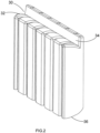
- a knife block 20 for storing knives 2 comprises a body portion 22 defining at least one slot 24 having a closed end 26 and an open end 28.
- a recess 30 is defined in the body portion 22, the recess 30 comprising a ledge 32 defining a convex surface which is angled downwardly when the knife block 20 is in the upright condition as shown in Figures 1 , 2 and 6 .
- the convex ledge engages a bolster 8 of knife 2 to direct the knife 2 against the closed end 26 of slot 24 when the knife is mounted in the slot 24.
- a wall 34 extends from the closed end 26 of slots 28.
- the wall 34 defines a surface against which the handles 4 and part of the spines 14 of knives are supported when the knives are mounted in slots 24.
- Slots 24 extend from the base 36 of body portion 22 all the way up to the convex ledge 32. The slots 24 therefore extend the full length of blades 10 of knives 2.
- Wall 34 and convex ledge 32 therefore define the sides of recess 30 in which a handle 4 of a knife 2 can be securely held.
- Ledge 32 defines a generally convex surface that is shaped to engage concave guide surfaces 38 formed on the bolsters 8 of the knives 2.
- the concave guide surfaces 38 engage convex ledge 32 and guide the knife into the slot 24, the spine 14 of knife 2 against the closed end 26 of slot 24 and the handle 4 and part of spine 14 of blade 10 against the wall 34.
- the body portion 22 is fashioned from one or more pieces of wood although other materials and methods of construction can be used to form the body portion 22 such as plastic or metal.
Landscapes
- Engineering & Computer Science (AREA)
- Food Science & Technology (AREA)
- Knives (AREA)
Claims (5)
- Eine kombinierte Messer- (2) und Messerblock(20)-Anordnung (20), die Folgendes beinhaltet:mindestens ein Messer (2), das eine Klinge (10) umfasst, welche eine Länge definiert, und einen Griff (4) und einen Kropf (8) umfasst; undeinen Messerblock (20) zum Aufbewahren von Messern, wobei der Messerblock Folgendes beinhaltet:einen Körperabschnitt (22), der mindestens einen Schlitz (24) zum Aufnehmen einer Klinge eines Messers definiert, wobei der mindestens eine Schlitz ein offenes Ende (28) aufweist, das sich im Gebrauch über die gesamte Länge der Klinge (10) eines Messers (2) erstreckt;eine Aussparung (30) in dem Körperabschnitt, die neben einem oberen Ende des mindestens einen Schlitzes angeordnet ist, dadurch gekennzeichnet, dass der mindestens eine Schlitz ein geschlossenes Ende (26) aufweist, das sich im Gebrauch über die gesamte Länge der Klinge eines Messers erstreckt, und dass die Aussparung einen Absatz (32) beinhaltet, der eine konvexe Oberfläche definiert, welche nach unten abgewinkelt ist, wenn sich der Messerblock in einem aufrechten Zustand befindet, um im Gebrauch in einen Kropf eines Messers einzugreifen, um das Messer gegen das geschlossene Ende des mindestens einen Schlitzes zu lenken.
- Anordnung gemäß Anspruch 1, die ferner einen Wandabschnitt (34) beinhaltet, der sich von dem geschlossenen Ende des mindestens einen Schlitzes erstreckt, wobei der Wandabschnitt konfiguriert ist, um in einen Griff (4) des Messers einzugreifen, wenn es in dem Messerblock eingehängt ist.
- Anordnung gemäß Anspruch 1 oder 2, wobei der Körperabschnitt ferner ein Basisende (36) beinhaltet, auf dem zu stehen der Messerblock konfiguriert ist, und wobei sich das offene Ende des mindestens einen Schlitzes von dem Basisende zu dem Absatz erstreckt.
- Anordnung gemäß einem der vorhergehenden Ansprüche, die ferner eine Vielzahl von Schlitzen (24), jeweils zum Aufnehmen eines Messers, beinhaltet, wobei jeder Schlitz ein geschlossenes Ende und ein offenes Ende aufweist.
- Anordnung gemäß einem der vorhergehenden Ansprüche, wobei das mindestens eine Messer (2) mindestens eine konkave Führungsfläche (38) beinhaltet, die eingerichtet ist, um gleitfähig in die konvexe Oberfläche des Absatzes einzugreifen.
Applications Claiming Priority (1)
| Application Number | Priority Date | Filing Date | Title |
|---|---|---|---|
| GB1901676.5A GB2581183B (en) | 2019-02-07 | 2019-02-07 | Knife block |
Publications (3)
| Publication Number | Publication Date |
|---|---|
| EP3692864A1 EP3692864A1 (de) | 2020-08-12 |
| EP3692864C0 EP3692864C0 (de) | 2025-03-12 |
| EP3692864B1 true EP3692864B1 (de) | 2025-03-12 |
Family
ID=65997102
Family Applications (1)
| Application Number | Title | Priority Date | Filing Date |
|---|---|---|---|
| EP20153669.5A Active EP3692864B1 (de) | 2019-02-07 | 2020-01-24 | Kombinierte messer und messerblock |
Country Status (4)
| Country | Link |
|---|---|
| US (1) | US11160402B2 (de) |
| EP (1) | EP3692864B1 (de) |
| CN (2) | CN111528672B (de) |
| GB (1) | GB2581183B (de) |
Families Citing this family (9)
| Publication number | Priority date | Publication date | Assignee | Title |
|---|---|---|---|---|
| GB2581183B (en) * | 2019-02-07 | 2021-02-17 | Robert Welch Designs Ltd | Knife block |
| USD917982S1 (en) * | 2019-02-07 | 2021-05-04 | Robert Welch Designs Ltd. | Knife block |
| USD949639S1 (en) * | 2020-07-01 | 2022-04-26 | Junxiang WEI | Knife holder |
| USD1010398S1 (en) * | 2021-05-08 | 2024-01-09 | Xiaoping Wang | Knife holder |
| USD1000915S1 (en) * | 2021-05-08 | 2023-10-10 | Xiaoping Wang | Knife holder |
| USD1016577S1 (en) * | 2021-08-10 | 2024-03-05 | Brothers Brands, Inc. | Knife blade |
| USD1111702S1 (en) * | 2022-08-19 | 2026-02-10 | Corelle Brands Holdings Inc. | Knife block |
| US12042070B2 (en) * | 2022-08-19 | 2024-07-23 | Instant Brands Holdings Inc. | Knife block and knife storage system |
| USD1081284S1 (en) | 2023-06-13 | 2025-07-01 | Robert Welch Designs Ltd. | Knife block |
Citations (2)
| Publication number | Priority date | Publication date | Assignee | Title |
|---|---|---|---|---|
| US1937424A (en) * | 1932-07-14 | 1933-11-28 | Philip T Champlin | Knife rack |
| USD800513S1 (en) * | 2015-12-28 | 2017-10-24 | Yunxing Liu | Knife block |
Family Cites Families (28)
| Publication number | Priority date | Publication date | Assignee | Title |
|---|---|---|---|---|
| US1569508A (en) * | 1924-01-24 | 1926-01-12 | Frank W Lee | Knife case |
| US2453800A (en) * | 1945-06-15 | 1948-11-16 | Jr George Henry Lowell | Knife rack |
| US2754008A (en) * | 1953-08-13 | 1956-07-10 | Chas D Briddell Inc | Knife holder |
| US3071252A (en) * | 1957-07-15 | 1963-01-01 | Hanschar Walter | Holder for bladed implements |
| DE3043421A1 (de) * | 1980-11-18 | 1982-07-08 | Alfa Institut für hauswirtschaftliche Produkt- und Verfahrens-Entwicklung GmbH, 6228 Eltville | Messerhalterung |
| GB2133681B (en) * | 1983-01-20 | 1986-11-26 | Fiskars Ab Oy | Knife holder with frontal slots |
| US4561548A (en) * | 1983-01-20 | 1985-12-31 | Oy Fiskars Ab | Knife holder with frontal slots |
| US4537315A (en) * | 1984-05-03 | 1985-08-27 | F & M Trading Company | Knife and/or steel storage unit |
| US4966339A (en) * | 1988-02-01 | 1990-10-30 | Lu Keh J | Knife stand |
| DE29902474U1 (de) * | 1999-02-12 | 1999-04-22 | IPS Handels GmbH, 20539 Hamburg | Messerhalter |
| CN2850497Y (zh) | 2004-08-02 | 2006-12-27 | 于尔根·施密特 | 刀类保持器 |
| US20060022094A1 (en) * | 2004-08-02 | 2006-02-02 | Jurgen Schmidt | Knife holder having support stand allowing use on counter or in drawer |
| USD575996S1 (en) | 2006-08-02 | 2008-09-02 | Robert Welch Designs Limited | Kitchen utensil holder |
| GB2445726A (en) | 2007-01-20 | 2008-07-23 | Robert Welch Designs Ltd | A knife storage and sharpening apparatus |
| GB2455517B (en) | 2007-12-11 | 2012-11-07 | Robert Welch Designs Ltd | Combination of a knife storage block and knife sharpener |
| CN201675814U (zh) | 2010-04-22 | 2010-12-22 | 黄振天 | 一种实木插刀架 |
| USD657635S1 (en) | 2011-05-13 | 2012-04-17 | Robert Welch Designs Ltd | Knife storage block |
| USD657634S1 (en) | 2011-05-13 | 2012-04-17 | Robert Welch Designs Ltd. | Knife storage block |
| CN202234995U (zh) | 2011-09-14 | 2012-05-30 | 杨希雅 | 防锈菜刀架 |
| USD712706S1 (en) | 2013-02-18 | 2014-09-09 | Robert Welch Designs Ltd. | Knife holder block |
| USD779893S1 (en) | 2014-05-19 | 2017-02-28 | Robert Welch Designs Ltd. | Knife insert for drawer |
| DE102015108734A1 (de) * | 2015-06-02 | 2016-12-08 | Friedrich Ug (Haftungsbeschränkt) | Halteblock für ein Besteckablagesystem für ein oder mehrere Besteckteile sowie Besteckablagesystem mit wenigstens zwei Halteblöcken |
| US10383468B2 (en) * | 2017-03-15 | 2019-08-20 | Corelle Brands Holdings Inc. | Adjustable cutlery implement restraining system |
| USD886542S1 (en) | 2017-06-06 | 2020-06-09 | Robert Welch Designs Ltd. | Knife block |
| WO2019017807A1 (ru) * | 2017-07-20 | 2019-01-24 | Игорь Ренатович АБДУЛИН | Подставка для ножей |
| FR3072549B1 (fr) * | 2017-10-19 | 2020-10-09 | Seb Sa | Support de couteaux avec dispositif de maintien |
| GB2581183B (en) * | 2019-02-07 | 2021-02-17 | Robert Welch Designs Ltd | Knife block |
| USD911122S1 (en) | 2019-02-07 | 2021-02-23 | Robert Welch Designs Ltd. | Knife block |
-
2019
- 2019-02-07 GB GB1901676.5A patent/GB2581183B/en active Active
-
2020
- 2020-01-24 EP EP20153669.5A patent/EP3692864B1/de active Active
- 2020-01-31 US US16/778,908 patent/US11160402B2/en active Active
- 2020-02-06 CN CN202010081794.4A patent/CN111528672B/zh active Active
- 2020-02-06 CN CN202020154691.1U patent/CN212089098U/zh active Active
Patent Citations (2)
| Publication number | Priority date | Publication date | Assignee | Title |
|---|---|---|---|---|
| US1937424A (en) * | 1932-07-14 | 1933-11-28 | Philip T Champlin | Knife rack |
| USD800513S1 (en) * | 2015-12-28 | 2017-10-24 | Yunxing Liu | Knife block |
Also Published As
| Publication number | Publication date |
|---|---|
| GB2581183A (en) | 2020-08-12 |
| EP3692864A1 (de) | 2020-08-12 |
| US20200253402A1 (en) | 2020-08-13 |
| CN111528672A (zh) | 2020-08-14 |
| GB201901676D0 (en) | 2019-03-27 |
| EP3692864C0 (de) | 2025-03-12 |
| GB2581183B (en) | 2021-02-17 |
| US11160402B2 (en) | 2021-11-02 |
| CN111528672B (zh) | 2022-07-05 |
| CN212089098U (zh) | 2020-12-08 |
Similar Documents
| Publication | Publication Date | Title |
|---|---|---|
| EP3692864B1 (de) | Kombinierte messer und messerblock | |
| US10843358B2 (en) | Produce slicer | |
| US4561548A (en) | Knife holder with frontal slots | |
| US8438961B2 (en) | Kitchen slicer | |
| US7267238B2 (en) | Retainer block for use with dish rack | |
| EP1946682B1 (de) | Vorrichtung zum Lagern und Schärfen von Messern | |
| US5907989A (en) | Food slicing rack devices | |
| US4807505A (en) | Bagel slicer | |
| US20030038098A1 (en) | Knife holder | |
| EP3213892B1 (de) | Schneidguthalter für gemüsehobel, sowie gemüsehobel | |
| US3018806A (en) | Apparatus for cutting bagels or the like | |
| EP3375579A1 (de) | Mandoline mit spiralisierereinsatz | |
| CA2906757C (en) | Slicer with adjustable slicing width | |
| US20130312581A1 (en) | Adjustable slicer and cutter | |
| KR102019638B1 (ko) | 안전 채칼 기구 | |
| US4531696A (en) | Knife holder and carrying case | |
| US7007583B1 (en) | Bagel cutter | |
| GB2133681A (en) | Knife holder with frontal slots | |
| CN202123532U (zh) | 新型等分器 | |
| CN209289336U (zh) | 组合切片刀 | |
| US10966449B2 (en) | Bean end cutting device | |
| CN2605975Y (zh) | 新式双刃省力菜刀 | |
| CN220661126U (zh) | 一种块茎类食品切削装置 | |
| CN221338675U (zh) | 一种便于长条状食材推切的切片器 | |
| CN217620708U (zh) | 一种多功能新型菜刀 |
Legal Events
| Date | Code | Title | Description |
|---|---|---|---|
| PUAI | Public reference made under article 153(3) epc to a published international application that has entered the european phase |
Free format text: ORIGINAL CODE: 0009012 |
|
| STAA | Information on the status of an ep patent application or granted ep patent |
Free format text: STATUS: REQUEST FOR EXAMINATION WAS MADE |
|
| 17P | Request for examination filed |
Effective date: 20200624 |
|
| AK | Designated contracting states |
Kind code of ref document: A1 Designated state(s): AL AT BE BG CH CY CZ DE DK EE ES FI FR GB GR HR HU IE IS IT LI LT LU LV MC MK MT NL NO PL PT RO RS SE SI SK SM TR |
|
| AX | Request for extension of the european patent |
Extension state: BA ME |
|
| RBV | Designated contracting states (corrected) |
Designated state(s): AL AT BE BG CH CY CZ DE DK EE ES FI FR GR HR HU IE IS IT LI LT LU LV MC MK MT NL NO PL PT RO RS SE SI SK SM TR |
|
| RIC1 | Information provided on ipc code assigned before grant |
Ipc: A47J 47/16 20060101ALI20221216BHEP Ipc: A47G 21/14 20060101AFI20221216BHEP |
|
| GRAP | Despatch of communication of intention to grant a patent |
Free format text: ORIGINAL CODE: EPIDOSNIGR1 |
|
| STAA | Information on the status of an ep patent application or granted ep patent |
Free format text: STATUS: GRANT OF PATENT IS INTENDED |
|
| INTG | Intention to grant announced |
Effective date: 20230315 |
|
| GRAJ | Information related to disapproval of communication of intention to grant by the applicant or resumption of examination proceedings by the epo deleted |
Free format text: ORIGINAL CODE: EPIDOSDIGR1 |
|
| STAA | Information on the status of an ep patent application or granted ep patent |
Free format text: STATUS: REQUEST FOR EXAMINATION WAS MADE |
|
| STAA | Information on the status of an ep patent application or granted ep patent |
Free format text: STATUS: EXAMINATION IS IN PROGRESS |
|
| INTC | Intention to grant announced (deleted) | ||
| 17Q | First examination report despatched |
Effective date: 20230524 |
|
| GRAP | Despatch of communication of intention to grant a patent |
Free format text: ORIGINAL CODE: EPIDOSNIGR1 |
|
| STAA | Information on the status of an ep patent application or granted ep patent |
Free format text: STATUS: GRANT OF PATENT IS INTENDED |
|
| INTG | Intention to grant announced |
Effective date: 20240917 |
|
| RIN1 | Information on inventor provided before grant (corrected) |
Inventor name: DEBRETTON GORDON, IAIN PAUL |
|
| GRAS | Grant fee paid |
Free format text: ORIGINAL CODE: EPIDOSNIGR3 |
|
| GRAA | (expected) grant |
Free format text: ORIGINAL CODE: 0009210 |
|
| STAA | Information on the status of an ep patent application or granted ep patent |
Free format text: STATUS: THE PATENT HAS BEEN GRANTED |
|
| AK | Designated contracting states |
Kind code of ref document: B1 Designated state(s): AL AT BE BG CH CY CZ DE DK EE ES FI FR GR HR HU IE IS IT LI LT LU LV MC MK MT NL NO PL PT RO RS SE SI SK SM TR |
|
| REG | Reference to a national code |
Ref country code: CH Ref legal event code: EP |
|
| REG | Reference to a national code |
Ref country code: DE Ref legal event code: R096 Ref document number: 602020047487 Country of ref document: DE |
|
| REG | Reference to a national code |
Ref country code: IE Ref legal event code: FG4D |
|
| U01 | Request for unitary effect filed |
Effective date: 20250401 |
|
| U07 | Unitary effect registered |
Designated state(s): AT BE BG DE DK EE FI FR IT LT LU LV MT NL PT RO SE SI Effective date: 20250407 |
|
| PG25 | Lapsed in a contracting state [announced via postgrant information from national office to epo] |
Ref country code: RS Free format text: LAPSE BECAUSE OF FAILURE TO SUBMIT A TRANSLATION OF THE DESCRIPTION OR TO PAY THE FEE WITHIN THE PRESCRIBED TIME-LIMIT Effective date: 20250612 |
|
| PG25 | Lapsed in a contracting state [announced via postgrant information from national office to epo] |
Ref country code: ES Free format text: LAPSE BECAUSE OF FAILURE TO SUBMIT A TRANSLATION OF THE DESCRIPTION OR TO PAY THE FEE WITHIN THE PRESCRIBED TIME-LIMIT Effective date: 20250312 |
|
| PG25 | Lapsed in a contracting state [announced via postgrant information from national office to epo] |
Ref country code: NO Free format text: LAPSE BECAUSE OF FAILURE TO SUBMIT A TRANSLATION OF THE DESCRIPTION OR TO PAY THE FEE WITHIN THE PRESCRIBED TIME-LIMIT Effective date: 20250612 |
|
| PG25 | Lapsed in a contracting state [announced via postgrant information from national office to epo] |
Ref country code: HR Free format text: LAPSE BECAUSE OF FAILURE TO SUBMIT A TRANSLATION OF THE DESCRIPTION OR TO PAY THE FEE WITHIN THE PRESCRIBED TIME-LIMIT Effective date: 20250312 |
|
| PG25 | Lapsed in a contracting state [announced via postgrant information from national office to epo] |
Ref country code: GR Free format text: LAPSE BECAUSE OF FAILURE TO SUBMIT A TRANSLATION OF THE DESCRIPTION OR TO PAY THE FEE WITHIN THE PRESCRIBED TIME-LIMIT Effective date: 20250613 |
|
| PG25 | Lapsed in a contracting state [announced via postgrant information from national office to epo] |
Ref country code: SM Free format text: LAPSE BECAUSE OF FAILURE TO SUBMIT A TRANSLATION OF THE DESCRIPTION OR TO PAY THE FEE WITHIN THE PRESCRIBED TIME-LIMIT Effective date: 20250312 |
|
| PG25 | Lapsed in a contracting state [announced via postgrant information from national office to epo] |
Ref country code: PL Free format text: LAPSE BECAUSE OF FAILURE TO SUBMIT A TRANSLATION OF THE DESCRIPTION OR TO PAY THE FEE WITHIN THE PRESCRIBED TIME-LIMIT Effective date: 20250312 |
|
| PG25 | Lapsed in a contracting state [announced via postgrant information from national office to epo] |
Ref country code: CZ Free format text: LAPSE BECAUSE OF FAILURE TO SUBMIT A TRANSLATION OF THE DESCRIPTION OR TO PAY THE FEE WITHIN THE PRESCRIBED TIME-LIMIT Effective date: 20250312 |
|
| PG25 | Lapsed in a contracting state [announced via postgrant information from national office to epo] |
Ref country code: SK Free format text: LAPSE BECAUSE OF FAILURE TO SUBMIT A TRANSLATION OF THE DESCRIPTION OR TO PAY THE FEE WITHIN THE PRESCRIBED TIME-LIMIT Effective date: 20250312 |
|
| PG25 | Lapsed in a contracting state [announced via postgrant information from national office to epo] |
Ref country code: IS Free format text: LAPSE BECAUSE OF FAILURE TO SUBMIT A TRANSLATION OF THE DESCRIPTION OR TO PAY THE FEE WITHIN THE PRESCRIBED TIME-LIMIT Effective date: 20250712 |
|
| PLBE | No opposition filed within time limit |
Free format text: ORIGINAL CODE: 0009261 |
|
| STAA | Information on the status of an ep patent application or granted ep patent |
Free format text: STATUS: NO OPPOSITION FILED WITHIN TIME LIMIT |
|
| REG | Reference to a national code |
Ref country code: CH Ref legal event code: L10 Free format text: ST27 STATUS EVENT CODE: U-0-0-L10-L00 (AS PROVIDED BY THE NATIONAL OFFICE) Effective date: 20260121 |
|
| 26N | No opposition filed |
Effective date: 20251215 |
|
| U20 | Renewal fee for the european patent with unitary effect paid |
Year of fee payment: 7 Effective date: 20260129 |