EP3691118B1 - Schwenk- und fächerantrieb für solarpaneele - Google Patents
Schwenk- und fächerantrieb für solarpaneele Download PDFInfo
- Publication number
- EP3691118B1 EP3691118B1 EP20164842.5A EP20164842A EP3691118B1 EP 3691118 B1 EP3691118 B1 EP 3691118B1 EP 20164842 A EP20164842 A EP 20164842A EP 3691118 B1 EP3691118 B1 EP 3691118B1
- Authority
- EP
- European Patent Office
- Prior art keywords
- fanning
- pivot
- swivel plate
- drive according
- swivel
- Prior art date
- Legal status (The legal status is an assumption and is not a legal conclusion. Google has not performed a legal analysis and makes no representation as to the accuracy of the status listed.)
- Active
Links
Images


Classifications
-
- F—MECHANICAL ENGINEERING; LIGHTING; HEATING; WEAPONS; BLASTING
- F16—ENGINEERING ELEMENTS AND UNITS; GENERAL MEASURES FOR PRODUCING AND MAINTAINING EFFECTIVE FUNCTIONING OF MACHINES OR INSTALLATIONS; THERMAL INSULATION IN GENERAL
- F16M—FRAMES, CASINGS OR BEDS OF ENGINES, MACHINES OR APPARATUS, NOT SPECIFIC TO ENGINES, MACHINES OR APPARATUS PROVIDED FOR ELSEWHERE; STANDS; SUPPORTS
- F16M11/00—Stands or trestles as supports for apparatus or articles placed thereon ; Stands for scientific apparatus such as gravitational force meters
- F16M11/02—Heads
- F16M11/04—Means for attachment of apparatus; Means allowing adjustment of the apparatus relatively to the stand
- F16M11/06—Means for attachment of apparatus; Means allowing adjustment of the apparatus relatively to the stand allowing pivoting
- F16M11/12—Means for attachment of apparatus; Means allowing adjustment of the apparatus relatively to the stand allowing pivoting in more than one direction
-
- F—MECHANICAL ENGINEERING; LIGHTING; HEATING; WEAPONS; BLASTING
- F16—ENGINEERING ELEMENTS AND UNITS; GENERAL MEASURES FOR PRODUCING AND MAINTAINING EFFECTIVE FUNCTIONING OF MACHINES OR INSTALLATIONS; THERMAL INSULATION IN GENERAL
- F16M—FRAMES, CASINGS OR BEDS OF ENGINES, MACHINES OR APPARATUS, NOT SPECIFIC TO ENGINES, MACHINES OR APPARATUS PROVIDED FOR ELSEWHERE; STANDS; SUPPORTS
- F16M13/00—Other supports for positioning apparatus or articles; Means for steadying hand-held apparatus or articles
- F16M13/02—Other supports for positioning apparatus or articles; Means for steadying hand-held apparatus or articles for supporting on, or attaching to, an object, e.g. tree, gate, window-frame, cycle
-
- F—MECHANICAL ENGINEERING; LIGHTING; HEATING; WEAPONS; BLASTING
- F24—HEATING; RANGES; VENTILATING
- F24S—SOLAR HEAT COLLECTORS; SOLAR HEAT SYSTEMS
- F24S30/00—Arrangements for moving or orienting solar heat collector modules
- F24S30/40—Arrangements for moving or orienting solar heat collector modules for rotary movement
- F24S30/45—Arrangements for moving or orienting solar heat collector modules for rotary movement with two rotation axes
- F24S30/452—Vertical primary axis
-
- F—MECHANICAL ENGINEERING; LIGHTING; HEATING; WEAPONS; BLASTING
- F24—HEATING; RANGES; VENTILATING
- F24S—SOLAR HEAT COLLECTORS; SOLAR HEAT SYSTEMS
- F24S30/00—Arrangements for moving or orienting solar heat collector modules
- F24S30/40—Arrangements for moving or orienting solar heat collector modules for rotary movement
- F24S30/48—Arrangements for moving or orienting solar heat collector modules for rotary movement with three or more rotation axes or with multiple degrees of freedom
-
- H—ELECTRICITY
- H01—ELECTRIC ELEMENTS
- H01Q—ANTENNAS, i.e. RADIO AERIALS
- H01Q1/00—Details of, or arrangements associated with, antennas
- H01Q1/12—Supports; Mounting means
- H01Q1/1235—Collapsible supports; Means for erecting a rigid antenna
-
- H—ELECTRICITY
- H01—ELECTRIC ELEMENTS
- H01Q—ANTENNAS, i.e. RADIO AERIALS
- H01Q1/00—Details of, or arrangements associated with, antennas
- H01Q1/12—Supports; Mounting means
- H01Q1/125—Means for positioning
-
- H—ELECTRICITY
- H02—GENERATION; CONVERSION OR DISTRIBUTION OF ELECTRIC POWER
- H02K—DYNAMO-ELECTRIC MACHINES
- H02K7/00—Arrangements for handling mechanical energy structurally associated with dynamo-electric machines, e.g. structural association with mechanical driving motors or auxiliary dynamo-electric machines
- H02K7/10—Structural association with clutches, brakes, gears, pulleys or mechanical starters
- H02K7/116—Structural association with clutches, brakes, gears, pulleys or mechanical starters with gears
- H02K7/1163—Structural association with clutches, brakes, gears, pulleys or mechanical starters with gears where at least two gears have non-parallel axes without having orbital motion
- H02K7/1166—Structural association with clutches, brakes, gears, pulleys or mechanical starters with gears where at least two gears have non-parallel axes without having orbital motion comprising worm and worm-wheel
-
- H—ELECTRICITY
- H02—GENERATION; CONVERSION OR DISTRIBUTION OF ELECTRIC POWER
- H02S—GENERATION OF ELECTRIC POWER BY CONVERSION OF INFRARED RADIATION, VISIBLE LIGHT OR ULTRAVIOLET LIGHT, e.g. USING PHOTOVOLTAIC [PV] MODULES
- H02S10/00—PV power plants; Combinations of PV energy systems with other systems for the generation of electric power
- H02S10/40—Mobile PV generator systems
-
- H—ELECTRICITY
- H02—GENERATION; CONVERSION OR DISTRIBUTION OF ELECTRIC POWER
- H02S—GENERATION OF ELECTRIC POWER BY CONVERSION OF INFRARED RADIATION, VISIBLE LIGHT OR ULTRAVIOLET LIGHT, e.g. USING PHOTOVOLTAIC [PV] MODULES
- H02S20/00—Supporting structures for PV modules
- H02S20/30—Supporting structures being movable or adjustable, e.g. for angle adjustment
-
- H—ELECTRICITY
- H02—GENERATION; CONVERSION OR DISTRIBUTION OF ELECTRIC POWER
- H02S—GENERATION OF ELECTRIC POWER BY CONVERSION OF INFRARED RADIATION, VISIBLE LIGHT OR ULTRAVIOLET LIGHT, e.g. USING PHOTOVOLTAIC [PV] MODULES
- H02S20/00—Supporting structures for PV modules
- H02S20/30—Supporting structures being movable or adjustable, e.g. for angle adjustment
- H02S20/32—Supporting structures being movable or adjustable, e.g. for angle adjustment specially adapted for solar tracking
-
- H—ELECTRICITY
- H02—GENERATION; CONVERSION OR DISTRIBUTION OF ELECTRIC POWER
- H02S—GENERATION OF ELECTRIC POWER BY CONVERSION OF INFRARED RADIATION, VISIBLE LIGHT OR ULTRAVIOLET LIGHT, e.g. USING PHOTOVOLTAIC [PV] MODULES
- H02S30/00—Structural details of PV modules other than those related to light conversion
- H02S30/20—Collapsible or foldable PV modules
-
- F—MECHANICAL ENGINEERING; LIGHTING; HEATING; WEAPONS; BLASTING
- F24—HEATING; RANGES; VENTILATING
- F24S—SOLAR HEAT COLLECTORS; SOLAR HEAT SYSTEMS
- F24S20/00—Solar heat collectors specially adapted for particular uses or environments
- F24S20/50—Rollable or foldable solar heat collector modules
-
- F—MECHANICAL ENGINEERING; LIGHTING; HEATING; WEAPONS; BLASTING
- F24—HEATING; RANGES; VENTILATING
- F24S—SOLAR HEAT COLLECTORS; SOLAR HEAT SYSTEMS
- F24S30/00—Arrangements for moving or orienting solar heat collector modules
- F24S2030/10—Special components
- F24S2030/11—Driving means
-
- F—MECHANICAL ENGINEERING; LIGHTING; HEATING; WEAPONS; BLASTING
- F24—HEATING; RANGES; VENTILATING
- F24S—SOLAR HEAT COLLECTORS; SOLAR HEAT SYSTEMS
- F24S30/00—Arrangements for moving or orienting solar heat collector modules
- F24S2030/10—Special components
- F24S2030/13—Transmissions
- F24S2030/134—Transmissions in the form of gearings or rack-and-pinion transmissions
-
- F—MECHANICAL ENGINEERING; LIGHTING; HEATING; WEAPONS; BLASTING
- F24—HEATING; RANGES; VENTILATING
- F24S—SOLAR HEAT COLLECTORS; SOLAR HEAT SYSTEMS
- F24S30/00—Arrangements for moving or orienting solar heat collector modules
- F24S2030/10—Special components
- F24S2030/19—Movement dampening means; Braking means
-
- Y—GENERAL TAGGING OF NEW TECHNOLOGICAL DEVELOPMENTS; GENERAL TAGGING OF CROSS-SECTIONAL TECHNOLOGIES SPANNING OVER SEVERAL SECTIONS OF THE IPC; TECHNICAL SUBJECTS COVERED BY FORMER USPC CROSS-REFERENCE ART COLLECTIONS [XRACs] AND DIGESTS
- Y02—TECHNOLOGIES OR APPLICATIONS FOR MITIGATION OR ADAPTATION AGAINST CLIMATE CHANGE
- Y02E—REDUCTION OF GREENHOUSE GAS [GHG] EMISSIONS, RELATED TO ENERGY GENERATION, TRANSMISSION OR DISTRIBUTION
- Y02E10/00—Energy generation through renewable energy sources
- Y02E10/40—Solar thermal energy, e.g. solar towers
- Y02E10/47—Mountings or tracking
-
- Y—GENERAL TAGGING OF NEW TECHNOLOGICAL DEVELOPMENTS; GENERAL TAGGING OF CROSS-SECTIONAL TECHNOLOGIES SPANNING OVER SEVERAL SECTIONS OF THE IPC; TECHNICAL SUBJECTS COVERED BY FORMER USPC CROSS-REFERENCE ART COLLECTIONS [XRACs] AND DIGESTS
- Y02—TECHNOLOGIES OR APPLICATIONS FOR MITIGATION OR ADAPTATION AGAINST CLIMATE CHANGE
- Y02E—REDUCTION OF GREENHOUSE GAS [GHG] EMISSIONS, RELATED TO ENERGY GENERATION, TRANSMISSION OR DISTRIBUTION
- Y02E10/00—Energy generation through renewable energy sources
- Y02E10/50—Photovoltaic [PV] energy
Definitions
- the present invention relates to a swivel and fan drive for solar panels, with a turntable and a swivel plate on which the solar panels can be stored in a fan-shaped manner around a fan axis.
- Solar panels that can be fanned out and tracked to the position of the sun using such a drive are, for example, AT 509.886 B1 , AT 512.680 B1 and AT 513.875 B1 known to the same applicant (whereby AT 509.886 A4 forms the basis for the two-part version of claim 1).
- the solar panels can be fanned out from a protected position, in which they are stacked on top of one another in a substantially congruent manner, into a fanned-out operating position and vice versa by rotating the fan shaft on which they are mounted.
- the top (or bottom) solar panel of the stack is connected to the fan shaft in a rotationally fixed manner, while the remaining solar panels can rotate on the fan shaft and, via drivers, drag the next solar panel - and this in turn drags the next solar panel, etc. - along when fanning out and fanning out.
- the solar panels In the fanned-out operating position, the solar panels can be aligned with the sun by pivoting the turntable and the pivot plate in azimuth and elevation angles.
- WO 2011/134004 A1 discloses a drive mechanism to align solar panels according to the position of the sun.
- the aim of the invention is to create a swivel and fan drive for such solar panels, which is simpler in construction, more space-saving and less prone to failure than the known designs.
- a swivel and fan drive of the type mentioned in the introduction which is characterized according to the invention in that at least one crank is rotatably mounted on the turntable and that a connecting rod couples the crank to the swivel plate in such a way that the turntable, the swivel plate, the crank and the connecting rod form a crank swing gear and a swivel movement of the crank swivels the swivel plate about a substantially horizontal axis.
- crank swing gear consisting of a turntable, swivel plate, crank and connecting rod results in a very compact, space-saving design in which the swivel plate can be swiveled into a rest position, e.g. for protection purposes, in which it can lie essentially parallel to and above the turntable.
- the swivel plate can be swiveled out into an approximately vertical end position in which the crank and connecting rod are preferably essentially stretched. This means that forces, e.g. as a result of impacts on the fan head, act on the axle bearings and not on more sensitive gear parts on the crank axle.
- crank and connecting rod this requires only very few parts, namely the crank and connecting rod, to build the swivel gear for the swivel plate, which simplifies production.
- the use of a crank swing gear for the swivel plate also leads to extremely trouble-free operation, since the crank remains fully rotatable and thus accidental over-rotation of a motor driving it cannot lead to any blockage or damage to the motor or mechanism.
- the bearing axis of the crank on the turntable is located lower than the second axis, which can be used, with appropriate dimensioning of the crank, connecting rod and effective joint distances between the turntable and swivel plate, to swivel the swivel plate, for example, from a horizontal rest position through any inclined position to an upright end position so that it can follow the position of the sun.
- the turntable has two high-rising bearing arms between which the said one end of the swivel plate is mounted.
- two cranks, each with a connecting rod, can preferably be provided, between which the other end of the swivel plate is mounted.
- cranks can be mounted on a common shaft that is mounted in bearing plates on the turntable, so that only one drive is required for both cranks.
- the turntable in particular - possibly with bearing arms and bearing plates, if present - can be manufactured in one piece, preferably as a cast part, which significantly simplifies the final assembly of the drive during production.
- the swivel and fan drive of the invention can be operated manually. However, it is preferably designed for motor operation, i.e. both for fully automatic tracking of the position of the sun by the solar panels and for fully automatic folding and unfolding of the panels, for example to move them into a protected fanned position at night or in wind and rain.
- the swivel movements around the three axes mentioned can be accomplished using any drive known in technology, for example hydraulic or pneumatic drives or electric servomotors, e.g. slow-rotating or geared electric motors or stepper motors.
- Gears known in technology e.g. planetary gears, or angle gears, e.g. planetary reversing gears, can be used as gears.
- electric motors with reduction worm gears are used, ie the crank(s) are preferably driven via a first worm gear by a first electric motor mounted on the turntable; and/or the turntable via a second worm gear by a second electric motor mounted on the base support; and/or the fan shaft via a third worm gear by a third electric motor mounted on the swivel plate.
- one of the other two drives is used instead of a separate third drive for the fan shaft:
- the solar panels can be fanned out and out during the azimuth rotation of the turntable or the elevation swivel of the swivel plate.
- the coupling is released again and the drives of the turntable and the swivel plate can again be used exclusively for the azimuth and elevation adjustment.
- the turntable drive is also used to drive the fan shaft, i.e. the fan shaft can be driven by the turntable or its drive via a coupling, and at the same time the coupling is automatically operated by pivoting the swivel plate.
- the coupling can be closed when the swivel plate is in a rest position and opened when the swivel plate is in a different swivel position.
- the rest position of the swivel plate is its horizontal position, parallel to and congruent with the turntable, in which the coupling closes.
- the turntable drive can now be used to fan out the solar panels, whereupon they are aligned in their elevation towards the sun using the swivel drive, which releases the coupling and makes the turntable drive usable again exclusively for azimuth adjustment.
- An advantageous practical embodiment of the invention is characterized in that the coupling is formed by a pinion driven by the rotary plate via a gear shaft and a gear ring seated on the fan shaft, which engages with the pinion when the swivel plate is swiveled into the rest position and disengages when the swivel plate is swiveled out from the rest position.
- the fan shaft can be selectively fixed in rotation relative to the swivel plate via a further coupling.
- This further coupling can also be actuated automatically during the swivel movement of the swivel plate, in particular the further coupling is open in the rest position of the swivel plate and closed in a different swivel position of the swivel plate.
- the further coupling can be a brake disk that is fixed in rotation with the fan shaft and spring-loaded against a braking surface of the swivel plate, which can be distanced from the braking surface by an actuating element of the turntable when the swivel plate is swiveled into the rest position, which enables automatic actuation of the second coupling without being prone to failure.
- the additional coupling being a brake pinion which is spring-loaded in a rotationally fixed but axially movable manner on the swivel plate and which has brake teeth for meshing engagement with the gear ring and can be pressed out of the meshing engagement against the spring loading when the swivel plate is pivoted into the rest position.
- a solar module 1 is shown with a plurality of lamellar solar panels 2, which are pivotably and fan-outably mounted on an anchor 4 via a pivoting and fan drive 3.
- the solar panels 2 can thus be moved from a first, in Fig. 1 shown fanned-out position, in which they lie essentially congruently on top of each other in a stack, into a second, in Fig. 2 shown fanned-out position, in which they are fanned out around a common fanning axis 5 and thus essentially lie next to one another, and vice versa.
- the fanning axis 5 can be adjusted in azimuth about a first, essentially vertical axis 6 and in elevation about a second, essentially horizontal axis 7 in order to align the fanned-out solar panels 2 with the sun and to track it.
- the anchor 4 can be of any type, for example a stand or tripod as shown, but also a part of a building, a ground anchor, a part of a ship, a vehicle, a container or the like.
- the solar panels 2 have an approximately circular sector shape, preferably with rounded corners ("petal shape") as shown, and complement each other in their fanned-out position ( Fig. 2 ) preferably - although not necessarily - to a full circle.
- twelve solar panels 2 are provided, each of which has a circular sector angle of approximately 30°, whereby the fan-out or swivel angle of a solar panel 2 is neighboring solar panel 2 is accordingly approximately 30°.
- Each solar panel 2 has a flat array of photovoltaic cells 8 on its top, e.g. in crystalline or organic form or in thin-film technology.
- the electrical connections and interconnections of the solar panels 2 and solar cells 8 are not shown for the sake of clarity; for example, the solar panels 2 are contacted via flexible connection cables or sliding contacts and rigid contact rings on the anchor 4 or the swivel and fan drive 3 and connected to the other energy transmission electrical systems.
- the Fig. 3 to 9 show the swivel and fan drive 3 for the solar panels 2 in detail.
- the swivel and fan drive 3 comprises a base support 9, here in the form of a ring flange, which can be screwed onto the upper end of the anchor 4, for example, via holes 10.
- a turntable 12 is mounted on the base support 9 via a ball bearing 11 so that it can at least swivel, preferably fully rotate, about the axis 6.
- the turntable 12 has at one end 13 two bearing arms 14 which project upwards at an angle and are spaced apart from one another, between which one end 15 of a swivel plate 16 is pivotably mounted about the axis 7.
- the swivel plate 16 could also be pivotably mounted on the turntable 12 in another way, for example with the aid of a hinge. It should be emphasized that the terms “turntable” and “swivel plate” do not refer literally to a plate or plate shape, but to their function, i.e.
- the turntable 12 could also have a shape other than a plate, for example in the form of a hub, a shaft socket, a block, etc.; and the swivel plate 16 could also have a shape other than a plate, e.g. be a hub, a socket, a block or a support of any shape.
- a fan shaft 18 is mounted via a ball bearing 17 around the fan axis 5 at least pivotable, preferably fully rotatable, mounted. From the fan shaft 18 is in the Fig. 3 to 9 only its drive-side end part, designed as a ring flange, is shown, to which, for example, via holes 19, the remaining Fig. 2 visible part of the fan shaft 18, which carries the solar panels 2, can be flanged.
- the solar panels 2 can be moved from the fanned position ( Fig. 1 ) into the fanned-out position ( Fig. 2 ) and vice versa.
- the top (or bottom) solar panel 2 of the stack Fig.
- each solar panel 2 (with the exception of the lowest solar panel 2) is optionally equipped with a sweeping lip on its back, which sweeps the solar panel 2 underneath when it is fanned out.
- the sweeping lip can be a rubber lip or a brush lip, for example, and can simultaneously form the drag bar.
- the pivoting of the pivot plate 16 relative to the rotary table 12 is carried out with the aid of at least one (here: two) cranks 20, which are seated on a common shaft 21, which is mounted in bearing brackets 22 of the rotary table 12, in such a way that the axis 21' of the shaft 21 is parallel to and at a distance from the pivot axis 7 of the pivot plate 16.
- the bearing brackets 22 can be formed by the foot areas of the bearing arms 14 or separately therefrom.
- cranks 20 are each connected at their ends facing away from the shaft 21 via a connecting rod 23 to the other end 24 of the swivel plate 16 is coupled to a pivot axis 25.
- cranks 20 and connecting rods 23 form a four-bar linkage, or more precisely a crank-and-swing mechanism, the "crank” of which is the cranks 20, the “swing” of which is the swivel plate 16, the "frame” of which is the rotary table 2 and the “coupling link” of which is the connecting rods 23.
- the frame length between the shaft axis 21' and the swivel axis 7, the swing length between the swivel axis 7 and the articulation axis 25, and the effective lengths of the crank 20 and connecting rods 23 determine the kinematics of the crank-and-swing mechanism, as is known in the art.
- the lengths mentioned are preferably - this is not mandatory - selected so that the swivel plate 16 can perform a swivel movement of approximately 90° from an approximately horizontal rest position ( Fig. 3 ) to an approximately vertical end position ( Fig. 4 ) and back when the cranks 20 make a full revolution.
- the shaft axis 21' of the cranks 20 is located obliquely below the pivot axis 7, so that in the rest position ( Fig. 3 ) the swivel plate 16 is approximately parallel to and above the rotary table 12 when the cranks 20 and connecting rod 23 are in their maximum shortened position. This results in a very small space requirement in the rest position, see Fig. 3 . In the maximum swiveled end position of Fig. 4 the cranks 20 and connecting rods 23 are in their maximum extended position.
- the movements of the swivel and fan drive 3 around one or more of the axes 5, 6, 7 can be carried out manually in the simplest case. However, the movements around one or more of the axes 5, 6, 7 are preferably carried out by appropriate drives, for example hydraulic or pneumatic cylinders, servomotors, stepper motors or the like. In the Fig. 3 to 7 a first embodiment is shown in which a geared electric drive is provided for each of the three movements.
- a first electric motor 26 with a flanged-on bevel gear 27 is mounted on the turntable 12, which drives one of the cranks 20 or its shaft 21 via a first worm gear 28.
- the first worm gear 28 comprises, for example, a worm driven by the electric motor 26 via the bevel gear 27, which engages a worm wheel sitting on a crank 20 or the shaft 21.
- a second electric motor 29 with flanged-on bevel gear 30 is mounted on the base support 9 and drives the turntable 12 via a second worm gear 31, which has, for example, a worm engaging in a worm wheel of the turntable 12.
- a third electric motor 32 with flanged-on bevel gear 33 is mounted on the swivel plate 16 and drives the fan shaft 18 via a third worm gear 34, for example again with the aid of a worm which engages in a worm wheel connected to the fan shaft 18.
- worm gears instead of one or more of the worm gears, other suitable gears, e.g. spur gears, planetary gears or angular gears, such as bevel gears, crown gears or planetary deflection gears, each with one or more gear stages, can also be used.
- suitable gears e.g. spur gears, planetary gears or angular gears, such as bevel gears, crown gears or planetary deflection gears, each with one or more gear stages, can also be used.
- a gear shaft 35 with an approximately vertical axis of rotation is mounted in bearings 36, 37 on the turntable 12 and/or one of its bearing brackets 22.
- the gear shaft 35 has a pinion 38 at its lower end, which meshes with a ring gear 39 that is formed on the outer circumference of a flange 40 of the base support 9.
- the gear shaft 35 carries a further pinion 41, which in the downwardly pivoted position of the pivot plate 16 ( Fig. 8 or 10) engages with a gear ring 42 which is formed on the outer circumference of the fan shaft 18.
- the second electric motor 29 drives both the turntable 12 and - via the engagement of the pinion 41 and gear ring 42 - the fan shaft 18, so that during the rotation about the axis 6, the solar panels 2 are simultaneously fanned out or fanned out about the axis 5.
- the pinion 41 and the gear ring 42 thus form a coupling between the turntable 12 or its drive and the fan shaft 18, which in the Fig. 8 and 10 shown rest position of the swivel plate 16 is closed.
- the clutch opens, see the Fig. 9 or 11, ie pinion 41 and gear ring 42 are disengaged, so that the electric motor 29 can now again be used exclusively for the rotary drive about the axis 6, ie the azimuth adjustment of the solar panels 2.
- the stacked solar panels 2 can be swivelled down in the fanned-out position by rotating them around the swivel axis 7 so that they Fig. 1 shown hanging protective position against wind and weather.
- the first electric motor 26 for the swivel plate drive can also be used for optionally driving the fan shaft 18, in which case a similar coupling is provided between the swivel plate 16 or its drive 26 and the fan shaft 18.
- the further coupling comprises in the design variant of the Fig. 8 and 9 a brake disc 45 which is connected to the fan shaft 18 in a rotationally fixed manner and is pre-tensioned against a braking surface 43 of the swivel plate 16 by means of a spring 44.
- the brake disc 45 is lifted from the braking surface 43 by an actuating member 46 attached to the turntable 12 when the swivel plate 16 is swivelled into the rest position, see Fig. 8
- the actuating member 46 is disengaged from the brake disk 45, so that the latter is pressed against the braking surface 43 by the spring 44 and thus the fan shaft 18 is rotationally fixed with respect to the swivel plate 16.
- the further coupling 43 - 46 is thus open in the rest position of the swivel plate 16 and closed in a different swivel position of the swivel plate 16.
- any other type of clutch can be used which enables the temporary fixing of the fan shaft 18 as shown.
- the braking function of the further clutch can alternatively be achieved by a brake pinion 47 or the like with brake teeth 48, which in the position of Fig. 10 approximately in alignment with the gear shaft 35 on the swivel plate 16, rotationally fixed, but axially movable, ie in the representation of Fig. 10 vertically movable, is mounted with a downward load by means of a spring 49.
- this brake pinion 47 with its brake teeth 48 is pressed by a spring into meshing engagement with the gear ring 42 in order to fix it in rotation.
- the rest position of the swivel plate 16 ( Fig. 10 ) it is pushed by the gear shaft 35 against its spring loading pushed out of the meshing engagement and thus releases the gear ring 42.
- clutches 41, 42 and 43 - 49 could also be operated manually or by means of electrical actuators, which can be controlled, for example, by electronics that also control the electric motors 26 and 29 accordingly.
Landscapes
- Engineering & Computer Science (AREA)
- General Engineering & Computer Science (AREA)
- Mechanical Engineering (AREA)
- Life Sciences & Earth Sciences (AREA)
- Sustainable Development (AREA)
- Combustion & Propulsion (AREA)
- Thermal Sciences (AREA)
- Chemical & Material Sciences (AREA)
- Sustainable Energy (AREA)
- Physics & Mathematics (AREA)
- Power Engineering (AREA)
- Photovoltaic Devices (AREA)
- Transmission Devices (AREA)
- Specific Sealing Or Ventilating Devices For Doors And Windows (AREA)
- Structures Of Non-Positive Displacement Pumps (AREA)
- Braking Arrangements (AREA)
Description
- Die vorliegende Erfindung betrifft einen Schwenk- und Fächerantrieb für Solarpaneele, mit einem Drehteller und einer Schwenkplatte, an der die Solarpaneele um eine Fächerachse herum ein- und auffächerbar lagerbar sind.
- Solarpaneele, die mittels eines derartigen Antriebs auffächerbar und dem Sonnenstand nachführbar sind, sind beispielsweise aus der
AT 509.886 B1 AT 512.680 B1 AT 513.875 B1 AT 509.886 A4 -
WO 2011/134004 A1 offenbart einen Antriebsmechanismus, um Solarpaneele nach dem Sonnenstand auszurichten. - Die Erfindung setzt sich zum Ziel, einen Schwenk- und Fächerantrieb für derartige Solarpaneele zu schaffen, welcher einfacher aufgebaut, platzsparender und weniger störungsanfällig ist als die bekannten Konstruktionen.
- Dieses Ziel wird mit einem Schwenk- und Fächerantrieb der einleitend genannten Art erreicht, welcher sich gemäß der Erfindung dadurch auszeichnet, dass zumindest eine Kurbel an dem Drehteller drehbar gelagert ist und dass ein Pleuel die Kurbel mit der Schwenkplatte so koppelt, dass der Drehteller, die Schwenkplatte, die Kurbel und das Pleuel ein Kurbelschwingengetriebe bilden und eine Schwenkbewegung der Kurbel die Schwenkplatte um eine im Wesentlichen horizontale Achse herum verschwenkt.
- Der Aufbau eines Kurbelschwingengetriebes aus Drehteller, Schwenkplatte, Kurbel und Pleuel führt zu einer sehr kompakten, platzsparenden Konstruktion, bei welcher die Schwenkplatte in eine Ruhestellung, z.B. zu Schutzzwecken, eingeschwenkt werden kann, in der sie im Wesentlichen parallel zu und über dem Drehteller liegen kann. Zu Transportzwecken kann die Schwenkplatte in eine etwa vertikale Endstellung ausgeschwenkt werden, in welcher Kurbel und Pleuel bevorzugt im Wesentlichen gestreckt sind. Dadurch wirken Kräfte, z.B. infolge von auf den Fächerkopf einwirkenden Stößen, auf die Achslager und nicht auf empfindlichere Getriebeteile an der Kurbelachse. Gleichzeitig benötigt dies nur sehr wenige Teile, nämlich Kurbel und Pleuel, um das Schwenkgetriebe für die Schwenkplatte aufzubauen, was die Fertigung vereinfacht. Die Verwendung eines Kurbelschwingengetriebes für die Schwenkplatte führt auch zu einem überaus störungsunanfälligen Betrieb, da die Kurbel voll drehfähig bleibt und somit ein versehentliches Überdrehen eines sie antreibenden Motors zu keinerlei Blockierung oder Beschädigung des Motors oder Mechanismus führen kann.
- Bevorzugt liegt die Lagerachse der Kurbel am Drehteller tiefer als die zweite Achse, was bei entsprechender Dimensionierung von Kurbel, Pleuel und wirksamen Gelenkabständen von Drehteller und Schwenkplatte dazu verwendet werden kann, die Schwenkplatte beispielsweise von einer horizontalen Ruhestellung über beliebige Schrägstellungen bis zu einer aufrechten Endstellung zu verschwenken, damit sie dem Sonnenstand folgen kann.
- Eine besonders robuste und platzsparende Ausführung ergibt sich, wenn gemäß einem bevorzugten Merkmal der Erfindung der Drehteller zwei hochragende Lagerarme aufweist, zwischen welchen das genannte eine Ende der Schwenkplatte gelagert ist. Aus denselben Gründen können bevorzugt zwei Kurbeln mit je einem Pleuel vorgesehen sein, zwischen welchen das genannte andere Ende der Schwenkplatte gelagert ist.
- In einer vorteilhaften Ausführungsform können dabei die Kurbeln auf einer gemeinsamen Welle sitzen, die in Lagerlaschen des Drehtellers gelagert ist, so dass nur ein Antrieb für beide Kurbeln erforderlich ist. Dabei kann insbesondere der Drehteller - gegebenenfalls mit Lagerarmen und Lagerlaschen, falls vorhanden - einstückig gefertigt sein, bevorzugt als ein Gussteil, was die Endmontage des Antriebs in der Fertigung wesentlich vereinfacht.
- Der Schwenk- und Fächerantrieb der Erfindung kann manuell betätigt werden. Bevorzugt ist er jedoch für einen Motorbetrieb ausgelegt, u.zw. sowohl für eine vollautomatische Sonnenstandsnachführung der Solarpaneele als auch deren vollautomatisches Ein- und Auffächern, beispielsweise um sie in der Nacht oder bei Wind und Regen in eine geschützte eingefächerte Stellung zu verbringen.
- Die Schwenkbewegungen um die genannten drei Achsen können dazu mittels jeglicher in der Technik bekannter Antriebe bewerkstelligt werden, beispielsweise hydraulischer oder pneumatischer Antriebe oder elektrischer Stellmotoren, z.B. langsamdrehender oder getriebeuntersetzter Elektromotoren oder Schrittschaltmotoren. Als Getriebe kommen dabei die in der Technik bekannten Getriebe, z.B. Planetengetriebe, auch als Winkelgetriebe, z.B. Planetenumlenkgetriebe, in Frage.
- In bevorzugten Ausführungsformen der Erfindung werden Elektromotoren mit untersetzenden Schneckengetrieben verwendet, d.h. die Kurbel(n) werden bevorzugt über ein erstes Schneckengetriebe von einem am Drehteller montierten ersten Elektromotor angetrieben; und/oder der Drehteller über ein zweites Schneckengetriebe von einem am Grundträger montierten zweiten Elektromotor; und/oder die Fächerwelle über ein drittes Schneckengetriebe von einem an der Schwenkplatte montierten dritten Elektromotor.
- Gemäß einem weiteren Aspekt der Erfindung wird anstelle eines eigenen dritten Antriebs für die Fächerwelle einer der beiden anderen Antriebe mitverwendet: Durch wahlweises Kuppeln der Fächerwelle mit dem Drehteller oder dessen Antrieb oder mit der Schwenkplatte oder deren Antrieb kann das Auf- und Einfächern der Solarpaneele während der Azimut-Verdrehung des Drehtellers oder Elevations-Verschwenkung der Schwenkplatte bewirkt werden. Nach dem gewünschten Auf- bzw. Einfächern der Solarpaneele wird die Kupplung wieder gelöst, und die Antriebe des Drehtellers und der Schwenkplatte können wieder ausschließlich für die Azimut- und Elevationsverstellung verwendet werden.
- Besonders günstig ist es, wenn für den Antrieb der Fächerwelle der Drehtellerantrieb mitverwendet wird, d.h. die Fächerwelle über eine Kupplung vom Drehteller oder dessen Antrieb antreibbar ist, und dabei gleichzeitig die Kupplung automatisch durch das Verschwenken der Schwenkplatte betätigt wird. So kann insbesondere die Kupplung in einer Ruhestellung der Schwenkplatte geschlossen und in einer davon abweichenden Schwenkstellung der Schwenkplatte geöffnet sein. Beispielsweise ist die Ruhestellung der Schwenkplatte deren horizontale, parallel über und deckungsgleich zum Drehteller liegende Stellung, in welcher die Kupplung schließt. Der Drehtellerantrieb kann nun zum Auffächern der Solarpaneele verwendet werden, woraufhin diese mittels des Schwenkantriebs in ihrer Elevation auf die Sonne ausgerichtet werden, was die Kupplung löst und den Drehtellerantrieb wieder ausschließlich für Azimutverstellung nutzbar macht.
- Eine vorteilhafte praktische Ausführungsform der Erfindung zeichnet sich dadurch aus, dass die Kupplung durch ein vom Drehteller über eine Getriebewelle angetriebenes Ritzel und einen auf der Fächerwelle sitzenden Zahnkranz gebildet ist, welcher beim Einschwenken der Schwenkplatte in die Ruhestellung in Eingriff mit dem Ritzel und beim Ausschwenken der Schwenkplatte aus der Ruhestellung außer Eingriff kommt. Dies ergibt ein automatisches Ein- und Auskuppeln der Kupplung zwischen Drehtellerantrieb und Fächerwelle beim Verschwenken der Schwenkplatte.
- Um zu verhindern, dass sich im Betrieb die Fächerwelle, nachdem die genannte Kupplung zur Separierung der Azimut- und Elevationsantriebe gelöst wurde, unbeabsichtigt verdreht, kann gemäß einem weiteren bevorzugten Merkmal der Erfindung die Fächerwelle über eine weitere Kupplung gegenüber der Schwenkplatte selektiv drehfixiert werden. Auch diese weitere Kupplung kann automatisch bei der Schwenkbewegung der Schwenkplatte betätigt werden, und zwar ist insbesondere die weitere Kupplung in der Ruhestellung der Schwenkplatte geöffnet und in einer davon abweichenden Schwenkstellung der Schwenkplatte geschlossen. In einer bevorzugten Ausführungsform dieser Variante kann dazu die weitere Kupplung eine mit der Fächerwelle drehfeste und gegen eine Bremsfläche der Schwenkplatte federnd vorgespannte Bremsscheibe sein, welche von einem Betätigungsglied des Drehtellers beim Verschwenken der Schwenkplatte in die Ruhestellung von der Bremsfläche distanzierbar ist, was eine störungsunanfällige automatische Betätigung der zweiten Kupplung ermöglicht. Dies kann alternativ auch dadurch bewirkt werden, dass die weitere Kupplung ein an der Schwenkplatte drehfest, aber axialbeweglich federbeaufschlagtes Bremsritzel ist, welches Bremszähne zum kämmenden Eingriff mit dem Zahnkranz hat und beim Verschwenken der Schwenkplatte in die Ruhestellung gegen die Federbeaufschlagung aus dem kämmenden Eingriff drückbar ist.
- Die Erfindung wird nachstehend anhand von in den beigeschlossenen Zeichnungen dargestellten Ausführungsbeispielen näher erläutert. In den Zeichnungen zeigen
- die
Fig. 1 und 2 ein Solarmodul mit auffächerbaren Solarpaneelen in zwei verschiedenen Betriebstellungen jeweils in einer schematischen Perspektivansicht von schräg oben; - die
Fig. 3 und 4 einen erfindungsgemäßen Schwenk- und Fächerantrieb für das Solarmodul derFig. 1 und 2 in zwei verschiedenen Betriebsstellungen, und zwar einmal in einer Perspektivansicht von schräg oben (Fig. 3 ) und einmal in einer Perspektivansicht von schräg unten (Fig. 4 ); - die
Fig. 5 bis 7 den Schwenk- und Fächerantrieb derFig. 3 und 4 in einer Seitenansicht (Fig. 5 ), einer Draufsicht (Fig. 6 ) und einer Rückansicht (Fig. 7 ); und - die
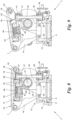
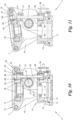
Fig. 8 bis 11 zwei Varianten einer alternativen Ausführungsform des Schwenk- und Fächerantriebs derFig. 3 bis 7 jeweils in zwei verschiedenen Betriebsstellungen im Schnitt. - In der
Fig. 1 und 2 ist ein Solarmodul 1 mit einer Vielzahl von lamellenförmigen Solarpaneelen 2 gezeigt, die über einen Schwenk- und Fächerantrieb 3 an einer Verankerung 4 schwenk- und auffächerbar gelagert sind. Die Solarpaneele 2 können so von einer ersten, inFig. 1 gezeigten eingefächerten Stellung, in der sie im Wesentlichen deckungsgleich in einem Stapel übereinanderliegen, in eine zweite, inFig. 2 gezeigte aufgefächerte Stellung, in welcher sie um eine gemeinsame Auffächerachse 5 herum aufgefächert sind und damit im Wesentlichen nebeneinanderliegen, verbracht werden und umgekehrt. Mit Hilfe des Schwenk- und Fächerantriebs 3 kann dabei die Auffächerachse 5 um eine erste, im Wesentlichen vertikale Achse 6 in Azimut und um eine zweite, im wesentliche horizontale Achse 7 in Elevation verstellt werden, um die aufgefächerten Solarpaneele 2 auf die Sonne auszurichten und dieser nachzuführen. Die Verankerung 4 kann dabei von jeglicher Art sein, beispielsweise ein Ständer bzw. Stativ wie gezeigt, aber auch ein Gebäudeteil, eine Bodenverankerung, ein Schiffsteil, ein Fahrzeug, ein Container od. dgl. - Die Solarpaneele 2 besitzen etwa Kreissektorform, bevorzugt mit abgerundeten Ecken ("Blütenblattform") wie dargestellt, und ergänzen sich in ihrer aufgefächerten Stellung (
Fig. 2 ) bevorzugt - wenn auch nicht zwingend - zu einem Vollkreis. Beispielsweise sind zwölf Solarpaneele 2 vorgesehen, deren Kreissektorwinkel jeweils ca. 30° beträgt, wobei der Auffächer- bzw. Verschwenkwinkel eines Solarpaneels 2 gegenüber seinem benachbarten Solarpaneel 2 dementsprechend etwa 30° beträgt. - Jedes Solarpaneel 2 weist auf seiner Oberseite ein flächiges Array von photovoltaischen Zellen 8 auf, z.B. in kristalliner oder organischer Form oder in Dünnschichttechnologie. Die elektrischen Anschlüsse und Verschaltungen der Solarpaneele 2 und Solarzellen 8 sind zwecks Übersichtlichkeit nicht gezeigt; beispielsweise werden die Solarpaneele 2 über flexible Anschlusskabel oder Schleifkontakte und starre Kontaktringe an der Verankerung 4 bzw. dem Schwenk- und Fächerantrieb 3 kontaktiert und an die weitere Energieübertragungselektrik angeschlossen.
- Die
Fig. 3 bis 9 zeigen den Schwenk- und Fächerantrieb 3 für die Solarpaneele 2 im Detail. Der Schwenk- und Fächerantrieb 3 umfasst einen Grundträger 9, hier in Form eines Ringflansches, der beispielsweise über Bohrungen 10 auf das obere Ende der Verankerung 4 geschraubt werden kann. Auf dem Grundträger 9 ist über ein Kugellager 11 ein Drehteller 12 um die Achse 6 zumindest schwenkbar, bevorzugt voll drehbar, gelagert. - Der Drehteller 12 besitzt an seinem einen Ende 13 zwei schräg nach oben hochragende und voneinander beabstandete Lagerarme 14, zwischen denen das eine Ende 15 einer Schwenkplatte 16 um die Achse 7 schwenkbar gelagert ist. Die Schwenkplatte 16 könnte auch auf andere Weise am Drehteller 12 schwenkbar gelagert sein, beispielsweise mit Hilfe eines Scharniers. Es ist hervorzuheben, dass sich die Begriffe "Drehteller" und "Schwenkplatte" nicht wörtlich auf eine Teller- bzw. Plattenform beziehen, sondern auf deren Funktion, d.h. der Drehteller 12 könnte auch eine andere als Tellerform haben, beispielsweise in Form einer Nabe, eines Wellenstutzens, eines Blocks usw.; und die Schwenkplatte 16 könnte auch eine andere Form als eine Plattenform haben, z.B. eine Nabe, ein Stutzen, ein Block oder ein beliebig geformter Träger sein.
- Auf bzw. in der Schwenkplatte 16 ist über ein Kugellager 17 eine Fächerwelle 18 um die Auffächerachse 5 zumindest schwenkbar, bevorzugt voll drehbar, gelagert. Von der Fächerwelle 18 ist in den
Fig. 3 bis 9 nur ihr antriebsseitiger, als Ringflansch ausgebildeter Endteil dargestellt, an welchen beispielsweise über Bohrungen 19 der restliche, inFig. 2 erkennbare Teil der Fächerwelle 18 angeflanscht werden kann, der die Solarpaneele 2 trägt. Durch Verdrehen der Fächerwelle 18 können die Solarpaneele 2 von der eingefächerten Stellung (Fig. 1 ) in die aufgefächerte Stellung (Fig. 2 ) verbracht werden und umgekehrt. Dazu kann z.B. das oberste (oder unterste) Solarpaneel 2 des Stapels (Fig. 1 ) mit der Fächerwelle 18 drehfest verbunden werden und das unterste (oder oberste) Solarpaneel 2 mit der Schwenkplatte 16 drehfest verbunden werden, wobei jeweils eines der Solarpaneele 2 mittels Schleppleisten, Schlepphaken, Mitnehmern oder dgl. das benachbarte Solarpaneel 2 beim Auf- oder Einfächern mitschleppt, bis alle Solarpaneele 2 auf- bzw. eingefächert sind. - Das Übereinandergleiten der Solarpaneele 2 bei dieser Schleppbewegung kann für eine Reinigung der Solarpaneele 2 ausgenützt werden. Zu diesem Zweck ist optional jedes Solarpaneel 2 (mit Ausnahme des untersten Solarpaneels 2) auf seiner Rückseite mit einer Kehrlippe ausgestattet, welche beim Auffächern das jeweils darunterliegende Solarpaneel 2 abkehrt. Die Kehrlippe kann beispielsweise eine Gummilippe oder eine Bürstenlippe sein und dabei gleichzeitig die Schleppleiste bilden.
- Das Verschwenken der Schwenkplatte 16 gegenüber dem Drehteller 12 erfolgt mit Hilfe zumindest einer (hier: zwei) Kurbeln 20, die auf einer gemeinsamen Welle 21 sitzen, welche in Lagerlaschen 22 des Drehtellers 12 gelagert sind, und zwar so, dass die Achse 21' der Welle 21 parallel zu und in einem Abstand von der Schwenkachse 7 der Schwenkplatte 16 liegt. Die Lagerlaschen 22 können durch die Fußbereiche der Lagerarme 14 oder davon gesondert ausgebildet sein.
- Die Kurbeln 20 sind jeweils an ihren der Welle 21 abgewandten Enden über ein Pleuel 23 mit dem dem Ende 15 gegenüberliegenden anderen Ende 24 der Schwenkplatte 16 an einer Anlenkachse 25 gekoppelt.
- Die vier Teile Drehteller 12, Schwenkplatte 16, Kurbeln 20 und Pleuel 23 bilden ein Viergelenk-Koppelgetriebe, u.zw. genauer ein Kurbelschwingengetriebe, dessen "Kurbel" die Kurbeln 20, dessen "Schwinge" die Schwenkplatte 16, dessen "Gestell" der Drehteller 2 und dessen "Koppelglied" die Pleuel 23 sind. Die Gestelllänge zwischen Wellenachse 21' und Schwenkachse 7, die Schwingenlänge zwischen Schwenkachse 7 und Anlenkachse 25, sowie die wirksamen Längen der Kurbel 20 und Pleuel 23 bestimmen die Kinematik des Kurbelschwingengetriebes, wie in der Technik bekannt. Die genannten Längen werden bevorzugt - dies ist nicht zwingend - so gewählt, dass die Schwenkplatte 16 eine etwa 90°-Schwenkbewegung von einer etwa horizontalen Ruhestellung (
Fig. 3 ) in eine etwa vertikale Endstellung (Fig. 4 ) ausführt und zurück, wenn die Kurbeln 20 eine volle Umdrehung ausführen. - Bevorzugt liegt dabei die Wellenachse 21' der Kurbeln 20 schräg unterhalb der Schwenkachse 7, so dass in der Ruhestellung (
Fig. 3 ) die Schwenkplatte 16 etwa parallel zu und über dem Drehteller 12 liegt, wenn die Kurbeln 20 und Pleuel 23 in ihrer maximal verkürzten Stellung sind. Dies hat einen sehr geringen Platzbedarf in der Ruhestellung zur Folge hat, sieheFig. 3 . In der maximal ausgeschwenkten Endstellung vonFig. 4 befinden sich die Kurbeln 20 und Pleuel 23 in ihrer maximal gestreckten Stellung. - Die Bewegungen des Schwenk- und Fächerantriebs 3 um eine oder mehrere der Achsen 5, 6, 7 können im einfachsten Fall manuell vorgenommen werden. Bevorzugt werden die Bewegungen um eine oder mehrere der Achsen 5, 6, 7 jedoch durch entsprechende Antriebe bewerkstelligt, beispielsweise Hydraulik- oder Pneumatikzylinder, Stellmotoren, Schrittschaltmotoren oder dgl. In den
Fig. 3 bis 7 ist eine erste Ausführungsform gezeigt, in welcher für jede der drei Bewegungen jeweils ein getriebeuntersetzter Elektroantrieb vorgesehen ist. - Dazu ist am Drehteller 12 ein erster Elektromotor 26 mit angeflanschtem Winkelgetriebe 27 montiert, der über ein erstes Schneckengetriebe 28 eine der Kurbeln 20 oder deren Welle 21 antreibt. Das erste Schneckengetriebe 28 umfasst beispielsweise eine vom Elektromotor 26 über das Winkelgetriebe 27 angetriebene Schnecke, die in ein auf einer Kurbel 20 oder der Welle 21 sitzendes Schneckenrad eingreift.
- Ein zweiter Elektromotor 29 mit angeflanschtem Winkelgetriebe 30 ist am Grundträger 9 montiert und treibt über ein zweites Schneckengetriebe 31, das beispielsweise eine in ein Schneckenrad des Drehtellers 12 eingreifende Schnecke aufweist, den Drehteller 12 an.
- Ein dritter Elektromotor 32 mit angeflanschtem Winkelgetriebe 33 ist an der Schwenkplatte 16 montiert und treibt über ein drittes Schneckengetriebe 34 die Fächerwelle 18 an, beispielsweise wieder mit Hilfe einer Schnecke, die in ein mit der Fächerwelle 18 verbundenes Schneckenrad eingreift.
- Es versteht sich, dass anstelle eines oder mehrerer der Schneckengetriebe auch geeignete andere Getriebe, z.B. Stirnrad-, Planeten- oder Winkelgetriebe, wie Kegelrad-, Kronenrad- oder Planetenumlenkgetriebe, u.zw. mit jeweils einer oder mehreren Getriebestufen, eingesetzt werden können.
- In den
Fig. 8 bis 11 sind Varianten einer zweiten Ausführungsform für den Antrieb der Fächerwelle 18 gezeigt, und zwar ist für diese kein eigener Elektroantrieb vorgesehen, sondern es wird hierfür der Antrieb des Drehtellers 12 wahlweise mitverwendet. Zu diesem Zweck ist auf dem Drehteller 12 und/oder einer seiner Lagerlaschen 22 eine Getriebewelle 35 mit etwa vertikaler Drehachse in Lagern 36, 37 gelagert. Die Getriebewelle 35 hat an ihrem unteren Ende ein Ritzel 38, das mit einem Zahnkranz 39 kämmt, der am Außenumfang eines Flansches 40 des Grundträgers 9 ausgebildet ist. Bei Drehung des Drehtellers 12 gegenüber dem Grundträger 9 bzw. dessen Flansch 40 wird somit die Getriebewelle 35 in Drehung versetzt. - An ihrem oberen Ende trägt die Getriebewelle 35 ein weiteres Ritzel 41, das in der herabgeschwenkten Stellung der Schwenkplatte 16 (
Fig. 8 bzw. 10) mit einem Zahnkranz 42 in Eingriff kommt, der am Außenumfang der Fächerwelle 18 ausgebildet ist. In dieser Stellung treibt somit der zweite Elektromotor 29 sowohl den Drehteller 12 als auch - über den Eingriff von Ritzel 41 und Zahnkranz 42 - die Fächerwelle 18 an, so dass während der Drehung um die Achse 6 gleichzeitig die Solarpaneele 2 um die Achse 5 auf- oder eingefächert werden. - Das Ritzel 41 und der Zahnkranz 42 bilden somit eine Kupplung zwischen dem Drehteller 12 bzw. dessen Antrieb und der Fächerwelle 18, die in der in den
Fig. 8 und10 gezeigten Ruhestellung der Schwenkplatte 16 geschlossen ist. Beim Hochschwenken der Schwenkplatte 16 öffnet die Kupplung, siehe dieFig. 9 bzw. 11, d.h. Ritzel 41 und Zahnkranz 42 kommen außer Eingriff, so dass nun der Elektromotor 29 wieder ausschließlich für den Drehantrieb um die Achse 6, d.h. die Azimutverstellung der Solarpaneele 2, verwendet werden kann. - Beim Herabschwenken bzw. Einschwenken der Schwenkplatte 16 in die Ruhestellung (
Fig. 8 bzw. 10) wird die Kupplung 41, 42 wieder geschlossen und es kann dann wieder der Elektromotor 29 zum z.B. Einfächern der Solarpaneele 2 mitverwendet werden. - Falls gewünscht, können in der eingefächerten Stellung die gestapelten Solarpaneele 2 durch Drehung um die Schwenkachse 7 herabgeschwenkt werden, so dass sie die in
Fig. 1 gezeigte herabhängende Schutzstellung gegenüber Wind und Wetter einnehmen. - Es versteht sich, dass anstelle des zweiten Elektromotors 29 des Drehtellerantriebs auch der erste Elektromotor 26 für des Schwenkplattenantriebs für das wahlweise Antreiben der Fächerwelle 18 mitverwendet werden kann, in welchem Fall eine gleichartige Kupplung zwischen der Schwenkplatte 16 bzw. deren Antrieb 26 und der Fächerwelle 18 vorgesehen wird.
- Wenn die Kupplung 41, 42 der Fächerwelle 18 in einer von der Ruhestellung (
Fig. 8 bzw. 10) abweichenden Stellung gelöst ist, kann eine weitere Kupplung dazu verwendet werden, um die Fächerwelle 18 gegenüber der Schwenkplatte 16 temporär drehzufixieren, damit eine unbeabsichtigte Änderung der Ein- bzw. Auffächerstellung der Solarpaneele 2 insbesondere während deren Azimut- und Elevationsverstellung vermieden wird. Die weitere Kupplung umfasst in der Ausführungsvariante derFig. 8 und 9 eine mit der Fächerwelle 18 drehfest verbundene und gegen eine Bremsfläche 43 der Schwenkplatte 16 mittels einer Feder 44 vorgespannte Bremsscheibe 45. Die Bremsscheibe 45 wird beim Verschwenken der Schwenkplatte 16 in die Ruhestellung durch ein am Drehteller 12 angebrachtes Betätigungsglied 46 von der Bremsfläche 43 abgehoben, sieheFig. 8 . Beim Hochschwenken der Schwenkplatte 16 gelangt das Betätigungsglied 46 außer Eingriff von der Bremsscheibe 45, so dass diese durch die Feder 44 gegen die Bremsfläche 43 gedrückt wird und damit die Fächerwelle 18 bezüglich der Schwenkplatte 16 drehfixiert. Die weitere Kupplung 43 - 46 ist somit in der Ruhestellung der Schwenkplatte 16 geöffnet und in einer davon abweichenden Schwenkstellung der Schwenkplatte 16 geschlossen. - Anstelle der gezeigten Bremsscheiben/Bremsflächen-Konstruktion der Kupplung 43 - 46 kann auch jede andere Art von Kupplung verwendet werden, welche die gezeigte temporäre Festsetzung der Fächerwelle 18 ermöglicht.
- Beispielsweise kann gemäß der in den
Fig. 10 und 11 dargestellten Variante die Bremsfunktion der weiteren Kupplung alternativ durch ein Bremsritzel 47 oder dgl. mit Bremszähnen 48 erzielt werden, welches in der Stellung vonFig. 10 etwa in Flucht mit der Getriebewelle 35 an der Schwenkplatte 16 drehfest, aber axialbeweglich, d.h. in der Darstellung vonFig. 10 vertikalbeweglich, mittels einer Feder 49 nach unten belastet gelagert ist. Beim Hochschwenken der Schwenkplatte 16 (Fig. 11 ) wird dieses Bremsritzel 47 mit seinen Bremszähnen 48 federbeaufschlagt in kämmenden Eingriff mit dem Zahnkranz 42 gedrückt, um diesen drehzufixieren. In der Ruhestellung der Schwenkplatte 16 (Fig. 10 ) wird es von der Getriebewelle 35 gegen seine Federbeaufschlagung aus dem kämmenden Eingriff geschoben und gibt so den Zahnkranz 42 frei. - Es versteht sich, dass die Kupplungen 41, 42 und 43 - 49 auch manuell oder mittels elektrischer Stellglieder betätigt werden könnten, welche z.B. von einer auch die Elektromotoren 26 und 29 entsprechend steuernden Elektronik gesteuert werden können.
Claims (20)
- Schwenk- und Fächerantrieb (3) für Solarpaneele (2), mit:einem Drehteller (12), undeiner Schwenkplatte (16), an der die Solarpaneele (2) um eine Fächerachse (5) herum ein- und auffächerbar lagerbar sind,dadurch gekennzeichnet, dass der Schwenk- und Fächerantrieb (3) weiter versehen ist mit:zumindest einer Kurbel (20), die an dem Drehteller (12) drehbar gelagert ist, undeinem Pleuel (23), das die Kurbel (20) mit der Schwenkplatte (16) so koppelt, dass der Drehteller (12), die Schwenkplatte (16), die Kurbel (20) und das Pleuel (23) ein Kurbelschwingengetriebe bilden und eine Schwenkbewegung der Kurbel (20) die Schwenkplatte (16) um eine im Wesentlichen horizontale Achse (7) herum verschwenkt.
- Schwenk- und Fächerantrieb nach Anspruch 1, bei welchem die Schwenkplatte (16) um die horizontale Achse (7) zwischen einer horizontalen und einer vertikalen Position verschwenkbar ist.
- Schwenk- und Fächerantrieb nach Anspruch 1 oder 2, bei welchem die Schwenkplatte (16) an dem Drehteller (12) um die im Wesentlichen horizontale Achse (7) schwenkbar gelagert ist, vorzugsweise zwischen einer Ruhestellung, in der die Schwenkplatte (16) im Wesentlichen parallel zu und über dem Drehteller (12) liegt, und einer etwa vertikalen Endstellung, in der Kurbel (20) und Pleuel (23) im Wesentlichen gestreckt sind.
- Schwenk- und Fächerantrieb nach Anspruch 3, bei welchem der Drehteller (12) ein Ende (15) der Schwenkplatte (16) um die genannte horizontale Achse (7) lagert und in einem Abstand dazu die zumindest eine Kurbel (20) lagert, welche über das Pleuel (23) mit dem anderen Ende (24) der Schwenkplatte (16) zur Bildung des Kurbelschwingengetriebes gekoppelt ist.
- Schwenk- und Fächerantrieb nach Anspruch 4, bei welchem der Drehteller (12) zwei hochragende Lagerarme (14) aufweist, zwischen welchen das genannte eine Ende (15) der Schwenkplatte (16) gelagert ist.
- Schwenk- und Fächerantrieb nach Anspruch 4 oder 5, bei welchem zwei Kurbeln (20) mit je einem Pleuel (23) vorgesehen sind und das genannte andere Ende (24) der Schwenkplatte (16) zwischen den beiden Pleueln (23) gelagert ist.
- Schwenk- und Fächerantrieb nach Anspruch 6, bei welcher die Kurbeln (20) auf einer gemeinsamen Welle (21) sitzen, die in Lagerlaschen (22) des Drehtellers (12) gelagert ist, wobei eine Achse (21') der Welle (21) vorzugsweise parallel zu und in einem Abstand von der horizontalen Achse (7) liegt.
- Schwenk- und Fächerantrieb nach einem der vorangehenden Ansprüche, bei welchem der Drehteller (12) - gegebenenfalls mit Lagerarmen (14) und Lagerlaschen (22), falls vorhanden - einstückig gefertigt ist, bevorzugt als ein Gussteil.
- Schwenk- und Fächerantrieb nach einem der vorangehenden Ansprüche, bei welchem eine Lagerachse (21') der Kurbel (20) am Drehteller (12) tiefer liegt als die horizontale Achse (7).
- Schwenk- und Fächerantrieb nach einem der vorangehenden Ansprüche, bei welchem die Kurbel(n) (20) über ein erstes Getriebe, z.B. ein erstes Schneckengetriebe (28), von einem am Drehteller (12) montierten ersten Antrieb wie z.B. einem ersten Elektromotor (26, 27) angetrieben ist/sind.
- Schwenk- und Fächerantrieb nach einem der vorangehenden Ansprüche, weiter mit einem Grundträger (9), an dem der Drehteller (12) um eine im Wesentlichen vertikale Achse (6) zumindest schwenkbar, bevorzugt voll drehbar, gelagert ist.
- Schwenk- und Fächerantrieb nach Anspruch 11, bei welchem der Drehteller (12) über ein zweites Getriebe, z.B. ein zweites Schneckengetriebe (31), von einem an dem Grundträger (9) montierten zweiten Antrieb wie z.B. einem zweiten Elektromotor (29, 30) angetrieben ist.
- Schwenk- und Fächerantrieb nach einem der vorangehenden Ansprüche, weiter mit einer Fächerwelle (18), die auf der Schwenkplatte (16) so gelagert ist, dass sie relativ zur Schwenkplatte (16) um die Fächerachse (5) herum schwenkbar ist.
- Schwenk- und Fächerantrieb nach Anspruch 13, weiter mit einer Anzahl von Solarpaneelen (2), die an der Fächerwelle (18) so angebracht sind, dass mindestens eines der Solarpaneele (2) zusammen mit der Fächerwelle (18) bewegbar ist.
- Schwenk- und Fächerantrieb nach Anspruch 13 oder 14, bei welchem die Fächerwelle (18) über ein drittes Getriebe (34), z.B. ein drittes Schneckengetriebe (34), von einem an der Schwenkplatte (16) montierten dritten Antrieb wie z.B. einem dritten Elektromotor (32, 33) antreibbar ist.
- Schwenk- und Fächerantrieb nach Anspruch 13 oder 14, bei welchem die Fächerwelle (18) über eine Kupplung von der Schwenkplatte (16) oder von einem Antrieb (26 - 28) der Schenkplatte (16) antreibbar ist.
- Schwenk- und Fächerantrieb nach Anspruch 13 oder 14, bei welchem die Fächerwelle (18) über eine Kupplung (41, 42) vom Drehteller (12) oder von einem Antrieb (29 - 31) des Drehtellers (12) antreibbar ist.
- Schwenk- und Fächerantrieb nach Anspruch 17, bei welchem die Kupplung (41, 42) durch das Verschwenken der Schwenkplatte (16) betätigbar ist.
- Schwenk- und Fächerantrieb nach Anspruch 18, bei welchem die Kupplung (41, 42) in einer Ruhestellung der Schwenkplatte (16) geschlossen und in einer davon abweichenden Schwenkstellung der Schwenkplatte (16) geöffnet ist.
- Schwenk- und Fächerantrieb nach Anspruch 19, bei welchem die Kupplung (41, 42) durch ein vom Drehteller (12) über eine Getriebewelle (35) angetriebenes Ritzel (41) und einen auf der Fächerwelle (18) sitzenden Zahnkranz (42) gebildet ist, welcher beim Einschwenken der Schwenkplatte (16) in die Ruhestellung in Eingriff mit dem Ritzel (41) und beim Ausschwenken der Schwenkplatte (16) aus der Ruhestellung außer Eingriff kommt.
Applications Claiming Priority (3)
| Application Number | Priority Date | Filing Date | Title |
|---|---|---|---|
| ATA50840/2015A AT517705B1 (de) | 2015-10-02 | 2015-10-02 | Schwenk- und Fächerantrieb für Solarpaneele |
| PCT/AT2016/060067 WO2017054026A1 (de) | 2015-10-02 | 2016-09-20 | Schwenk- und fächerantrieb für solarpaneele |
| EP16793730.9A EP3357157B1 (de) | 2015-10-02 | 2016-09-20 | Schwenk- und fächerantrieb für solarpaneele |
Related Parent Applications (1)
| Application Number | Title | Priority Date | Filing Date |
|---|---|---|---|
| EP16793730.9A Division EP3357157B1 (de) | 2015-10-02 | 2016-09-20 | Schwenk- und fächerantrieb für solarpaneele |
Publications (2)
| Publication Number | Publication Date |
|---|---|
| EP3691118A1 EP3691118A1 (de) | 2020-08-05 |
| EP3691118B1 true EP3691118B1 (de) | 2024-11-06 |
Family
ID=57256007
Family Applications (5)
| Application Number | Title | Priority Date | Filing Date |
|---|---|---|---|
| EP16793730.9A Active EP3357157B1 (de) | 2015-10-02 | 2016-09-20 | Schwenk- und fächerantrieb für solarpaneele |
| EP20164839.1A Withdrawn EP3691117A1 (de) | 2015-10-02 | 2016-09-20 | Schwenk- und fächerantrieb für solarpaneele |
| EP20164842.5A Active EP3691118B1 (de) | 2015-10-02 | 2016-09-20 | Schwenk- und fächerantrieb für solarpaneele |
| EP20164840.9A Active EP3716471B1 (de) | 2015-10-02 | 2016-09-20 | Schwenk- und fächerantrieb für solarpaneele |
| EP20164837.5A Withdrawn EP3691116A1 (de) | 2015-10-02 | 2016-09-20 | Schwenk- und fächerantrieb für solarpaneele |
Family Applications Before (2)
| Application Number | Title | Priority Date | Filing Date |
|---|---|---|---|
| EP16793730.9A Active EP3357157B1 (de) | 2015-10-02 | 2016-09-20 | Schwenk- und fächerantrieb für solarpaneele |
| EP20164839.1A Withdrawn EP3691117A1 (de) | 2015-10-02 | 2016-09-20 | Schwenk- und fächerantrieb für solarpaneele |
Family Applications After (2)
| Application Number | Title | Priority Date | Filing Date |
|---|---|---|---|
| EP20164840.9A Active EP3716471B1 (de) | 2015-10-02 | 2016-09-20 | Schwenk- und fächerantrieb für solarpaneele |
| EP20164837.5A Withdrawn EP3691116A1 (de) | 2015-10-02 | 2016-09-20 | Schwenk- und fächerantrieb für solarpaneele |
Country Status (21)
| Country | Link |
|---|---|
| US (2) | US10298173B2 (de) |
| EP (5) | EP3357157B1 (de) |
| JP (2) | JP6885932B2 (de) |
| KR (1) | KR102709747B1 (de) |
| CN (2) | CN108391461B (de) |
| AT (1) | AT517705B1 (de) |
| AU (2) | AU2016333140B2 (de) |
| CL (1) | CL2018000826A1 (de) |
| DK (1) | DK3357157T3 (de) |
| ES (3) | ES3009007T3 (de) |
| HR (1) | HRP20251537T1 (de) |
| IL (2) | IL258388B (de) |
| MX (2) | MX2018003917A (de) |
| PH (1) | PH12018500728A1 (de) |
| PL (1) | PL3716471T4 (de) |
| PT (1) | PT3357157T (de) |
| RS (1) | RS67495B1 (de) |
| SG (2) | SG11201802664SA (de) |
| SM (1) | SMT202500485T1 (de) |
| WO (1) | WO2017054026A1 (de) |
| ZA (1) | ZA201802077B (de) |
Families Citing this family (17)
| Publication number | Priority date | Publication date | Assignee | Title |
|---|---|---|---|---|
| AT517705B1 (de) * | 2015-10-02 | 2017-04-15 | Smart Flower Energy Tech Gmbh | Schwenk- und Fächerantrieb für Solarpaneele |
| CN109194269B (zh) * | 2018-10-23 | 2023-10-17 | 西南交通大学 | 一种折叠扇形板的机构 |
| USD909960S1 (en) * | 2018-11-14 | 2021-02-09 | Alexander Swatek | Solar power module |
| CO2018014418A1 (es) * | 2018-12-31 | 2019-01-18 | Arbulu Saavedra Mario Ricardo | Sistema desplegable de paneles solares con mecanismo posicionador para captar la luz solar |
| DE102019003279B4 (de) * | 2019-05-08 | 2021-10-14 | Mbda Deutschland Gmbh | Vorrichtung zum Schwenken eines kippbaren Mastes, Teleskopmastanordnung, Verfahren zum Aufrichten und Verfahren zum Ablegen eines Teleskopmastes |
| MA46073A1 (fr) * | 2019-06-04 | 2020-12-31 | Jilali Toumi | Dispositif porte plaques solaires pour voitures |
| CH717565A1 (fr) | 2020-06-25 | 2021-12-30 | Planair Sa | Installation photovoltaïque et procédé de construction d'une telle installation. |
| USD1011272S1 (en) * | 2020-07-28 | 2024-01-16 | Palm Energy Systems Llc | Solar collector pillar |
| CN112152556B (zh) * | 2020-08-12 | 2024-09-13 | 常熟理工学院 | 家用自动折叠太阳能面板 |
| EP4423905A1 (de) | 2021-10-27 | 2024-09-04 | Planair SA | Fotovoltaische anlage |
| US11987976B2 (en) * | 2021-11-10 | 2024-05-21 | Khaled Elbehiery | Rotating building assembly |
| CN114759871A (zh) * | 2022-04-06 | 2022-07-15 | 同辉电子科技股份有限公司 | 一种基于风速监测的太阳能板折叠机构 |
| CN115027306B (zh) * | 2022-07-30 | 2025-08-15 | 山东鼎盛电气设备有限公司 | 一种露天停车场智能太阳能充电桩 |
| TWI833348B (zh) * | 2022-09-12 | 2024-02-21 | 賴彥光 | 樹狀太陽能集電柱及集電系統 |
| USD1073591S1 (en) * | 2023-01-18 | 2025-05-06 | Xiamen Topunive Technology Co., Ltd. | Solar charging pile |
| DE102023124473A1 (de) * | 2023-09-11 | 2025-03-13 | Auma Riester Gmbh & Co. Kg | Stellantrieb und Baugruppe |
| USD1126142S1 (en) * | 2023-11-15 | 2026-05-12 | XIAMEN TOPUNIVE TECHNOLOGY Co.,Ltd. | Solar charging pile |
Family Cites Families (34)
| Publication number | Priority date | Publication date | Assignee | Title |
|---|---|---|---|---|
| BE684729A (de) * | 1966-11-10 | 1967-01-03 | ||
| ES473356A1 (es) * | 1978-09-14 | 1979-11-01 | Sener Ing & Sist | Perfeccionamientos en heliostatos |
| DE3131612A1 (de) * | 1981-08-10 | 1983-02-24 | Zahnräderfabrik Renk AG, 8900 Augsburg | Getriebe zur positionierung von sonnenenergie-kollektoren |
| US4552438A (en) * | 1984-01-09 | 1985-11-12 | The United States Of America As Represented By The United States Department Of Energy | Cable tensioned membrane solar collector module with variable tension control |
| US5517204A (en) * | 1992-03-10 | 1996-05-14 | Tokimec Inc. | Antenna directing apparatus |
| JP2002081760A (ja) | 2000-09-08 | 2002-03-22 | Mitsui Eng & Shipbuild Co Ltd | 太陽エネルギー利用システム |
| DE20200609U1 (de) * | 2002-01-16 | 2003-06-05 | Robert Bosch Gmbh, 70469 Stuttgart | Mobile Solar-Akku-Ladestation |
| ES2342688T3 (es) * | 2006-05-24 | 2010-07-12 | Flender Tubingen Gmbh | Disposicion de accionamiento con dos ejes. |
| US8381718B1 (en) * | 2006-10-20 | 2013-02-26 | Idealab | Actuator for controlling rotation about two axes using a single motor |
| US7878192B2 (en) * | 2006-11-22 | 2011-02-01 | Theodore Edward Larsen | Adjustable solar collector and method of use |
| KR100891500B1 (ko) | 2007-09-11 | 2009-04-06 | 성재욱 | 무인 자동설비용 금형장치 |
| KR100934175B1 (ko) * | 2007-10-11 | 2009-12-29 | 박태선 | 태양광 발전 트래커 |
| US9214892B2 (en) * | 2007-11-21 | 2015-12-15 | Orbital Atk, Inc. | Solar arrays |
| US8168883B2 (en) * | 2008-05-29 | 2012-05-01 | Moses Clark | Adjustable solar powerer |
| US8662072B2 (en) * | 2008-10-01 | 2014-03-04 | Steven Polk | Solar collector |
| GB2469344B (en) * | 2009-07-23 | 2011-08-24 | Iain Chapman | Moveable mounting |
| US8168931B1 (en) * | 2009-12-09 | 2012-05-01 | Concrete Systems, Inc. | Solar tracking device |
| KR101187925B1 (ko) * | 2010-04-06 | 2012-10-05 | 박용우 | 한 개의 모터로 2축 구동이 가능한 태양광발전용 추적시스템 |
| WO2011134004A1 (en) * | 2010-04-27 | 2011-11-03 | Upton Ecoforlife Solar Trackers Pty. Ltd. | Solar tracking system |
| US20110277748A1 (en) * | 2010-05-12 | 2011-11-17 | Raymond Chu | Closable Solar Collector |
| AT509886B1 (de) * | 2010-06-29 | 2011-12-15 | Alexander Swatek | Solarmodul |
| WO2012073705A1 (ja) * | 2010-11-30 | 2012-06-07 | 株式会社Sp電機 | 太陽光発電装置 |
| WO2012116102A2 (en) * | 2011-02-22 | 2012-08-30 | Sunpower Corporation | Solar tracker drive |
| WO2013115832A2 (en) * | 2011-04-07 | 2013-08-08 | Steven Polk | Solar energy collector |
| US20120285506A1 (en) * | 2011-05-13 | 2012-11-15 | Chieh-Hsing Kuo | Solar Tracker |
| CN103858336B (zh) * | 2011-08-15 | 2017-12-08 | 摩根阳光公司 | 用于太阳跟踪的自稳定设备 |
| DE102012021106A1 (de) * | 2012-02-17 | 2013-08-22 | Heidelberger Druckmaschinen Ag | Vorrichtung für den Einsatz in Systemen zur Nutzung von Solarenergie |
| AT512680B1 (de) * | 2012-04-02 | 2014-05-15 | Smart Flower Energy Technology Gmbh | Solarmodul |
| KR101304647B1 (ko) * | 2012-11-24 | 2013-09-06 | 류지연 | 태양추적장치 및 그 운영방법 |
| AT513875B1 (de) * | 2013-01-23 | 2015-01-15 | Smart Flower Energy Technology Gmbh | Solarmodul |
| FR3011149B1 (fr) * | 2013-09-26 | 2019-03-15 | Servitronique | Dispositif de reglage a 2 axes d'une partie d'installation en particulier d'un ou plusieurs panneaux solaires |
| CN104156005B (zh) * | 2014-08-07 | 2017-10-24 | 福建农林大学 | 一种太阳能追光装置 |
| CN104539230A (zh) * | 2014-12-26 | 2015-04-22 | 金海新源电气江苏有限公司 | 一种光伏太阳能旋转支架 |
| AT517705B1 (de) | 2015-10-02 | 2017-04-15 | Smart Flower Energy Tech Gmbh | Schwenk- und Fächerantrieb für Solarpaneele |
-
2015
- 2015-10-02 AT ATA50840/2015A patent/AT517705B1/de active
-
2016
- 2016-09-20 HR HRP20251537TT patent/HRP20251537T1/hr unknown
- 2016-09-20 AU AU2016333140A patent/AU2016333140B2/en active Active
- 2016-09-20 ES ES20164842T patent/ES3009007T3/es active Active
- 2016-09-20 SG SG11201802664SA patent/SG11201802664SA/en unknown
- 2016-09-20 DK DK16793730.9T patent/DK3357157T3/da active
- 2016-09-20 SM SM20250485T patent/SMT202500485T1/it unknown
- 2016-09-20 PT PT167937309T patent/PT3357157T/pt unknown
- 2016-09-20 CN CN201680062887.4A patent/CN108391461B/zh active Active
- 2016-09-20 EP EP16793730.9A patent/EP3357157B1/de active Active
- 2016-09-20 SG SG10201912476SA patent/SG10201912476SA/en unknown
- 2016-09-20 ES ES16793730T patent/ES2811324T3/es active Active
- 2016-09-20 EP EP20164839.1A patent/EP3691117A1/de not_active Withdrawn
- 2016-09-20 EP EP20164842.5A patent/EP3691118B1/de active Active
- 2016-09-20 CN CN202010499948.1A patent/CN111726059B/zh active Active
- 2016-09-20 EP EP20164840.9A patent/EP3716471B1/de active Active
- 2016-09-20 JP JP2018517205A patent/JP6885932B2/ja active Active
- 2016-09-20 ES ES20164840T patent/ES3057857T3/es active Active
- 2016-09-20 PL PL20164840.9T patent/PL3716471T4/pl unknown
- 2016-09-20 US US15/764,365 patent/US10298173B2/en active Active
- 2016-09-20 MX MX2018003917A patent/MX2018003917A/es unknown
- 2016-09-20 WO PCT/AT2016/060067 patent/WO2017054026A1/de not_active Ceased
- 2016-09-20 KR KR1020187011611A patent/KR102709747B1/ko active Active
- 2016-09-20 EP EP20164837.5A patent/EP3691116A1/de not_active Withdrawn
- 2016-09-20 RS RS20251246A patent/RS67495B1/sr unknown
-
2018
- 2018-03-27 IL IL258388A patent/IL258388B/en unknown
- 2018-03-28 ZA ZA2018/02077A patent/ZA201802077B/en unknown
- 2018-03-28 MX MX2023003907A patent/MX2023003907A/es unknown
- 2018-03-29 CL CL2018000826A patent/CL2018000826A1/es unknown
- 2018-04-02 PH PH12018500728A patent/PH12018500728A1/en unknown
-
2019
- 2019-02-13 US US16/274,633 patent/US10454410B2/en active Active
-
2021
- 2021-05-13 JP JP2021081696A patent/JP7127189B2/ja active Active
- 2021-07-27 IL IL285159A patent/IL285159B/en unknown
-
2022
- 2022-04-29 AU AU2022202838A patent/AU2022202838B2/en active Active
Also Published As
Similar Documents
| Publication | Publication Date | Title |
|---|---|---|
| EP3716471B1 (de) | Schwenk- und fächerantrieb für solarpaneele | |
| EP2949038B1 (de) | Solarmodul | |
| EP2834576B1 (de) | Solarmodul | |
| EP1710651B1 (de) | Nachführeinrichtung für eine Photovoltaikanlage | |
| EP2663720A1 (de) | Faltladenanordnung mit mehreren in sich starren faltladenelementen, insbesondere mit abwechselnd ausknickenden und nicht ausknickenden elementkanten | |
| DE102009034144A1 (de) | Nachführeinrichtung für eine Photovoltaikanlage | |
| DE2515154A1 (de) | Zelt | |
| WO2018127563A1 (de) | Monitorsystem | |
| DE102016123372A1 (de) | Kameraarm | |
| EP1788322A1 (de) | Montierung für eine Gruppe von Solarmodulen | |
| DE202008015767U1 (de) | Nachführungseinrichtung für plattenförmige Solarmodule | |
| DE2419343A1 (de) | Betaetigungseinrichtung fuer kraftfahrzeugfenster | |
| DE102009022876A1 (de) | Nachführeinheit sowie Sonnenkollektor- oder Photovoltaikeinheit | |
| WO2008003431A1 (de) | Nachführungsvorrichtung für sonnenkollektoren | |
| DE3321599A1 (de) | Fahrgeschaeft | |
| DE102008030747A1 (de) | Nachführeinrichtung | |
| DE3029502A1 (de) | Heuwerbungsmaschine | |
| DE202010014436U1 (de) | Bodenwalze | |
| DE202012100137U1 (de) | Satteldachkonstruktion | |
| DE202006005881U1 (de) | Vorrichtung zur Nachführung von Solarzellen | |
| DE69808417T2 (de) | Gerät zum versetzen von auf dem boden liegendem erntegut, insbesondere kreiselheuwender und montageeinheit dafür | |
| DE102023106674A1 (de) | Aufständerungssystem | |
| DE202025104466U1 (de) | Lamellenanordnung | |
| DE202020106700U1 (de) | Footballtor | |
| DE8317459U1 (de) | Fahrgeschaeft |
Legal Events
| Date | Code | Title | Description |
|---|---|---|---|
| PUAI | Public reference made under article 153(3) epc to a published international application that has entered the european phase |
Free format text: ORIGINAL CODE: 0009012 |
|
| STAA | Information on the status of an ep patent application or granted ep patent |
Free format text: STATUS: THE APPLICATION HAS BEEN PUBLISHED |
|
| AC | Divisional application: reference to earlier application |
Ref document number: 3357157 Country of ref document: EP Kind code of ref document: P |
|
| AK | Designated contracting states |
Kind code of ref document: A1 Designated state(s): AL AT BE BG CH CY CZ DE DK EE ES FI FR GB GR HR HU IE IS IT LI LT LU LV MC MK MT NL NO PL PT RO RS SE SI SK SM TR |
|
| STAA | Information on the status of an ep patent application or granted ep patent |
Free format text: STATUS: REQUEST FOR EXAMINATION WAS MADE |
|
| 17P | Request for examination filed |
Effective date: 20210112 |
|
| RBV | Designated contracting states (corrected) |
Designated state(s): AL AT BE BG CH CY CZ DE DK EE ES FI FR GB GR HR HU IE IS IT LI LT LU LV MC MK MT NL NO PL PT RO RS SE SI SK SM TR |
|
| REG | Reference to a national code |
Ref country code: HK Ref legal event code: DE Ref document number: 40034628 Country of ref document: HK |
|
| RIC1 | Information provided on ipc code assigned before grant |
Ipc: F24S 30/00 20180101ALI20240404BHEP Ipc: F24S 30/48 20180101ALI20240404BHEP Ipc: F24S 30/452 20180101ALI20240404BHEP Ipc: H02S 20/30 20140101AFI20240404BHEP |
|
| GRAP | Despatch of communication of intention to grant a patent |
Free format text: ORIGINAL CODE: EPIDOSNIGR1 |
|
| STAA | Information on the status of an ep patent application or granted ep patent |
Free format text: STATUS: GRANT OF PATENT IS INTENDED |
|
| INTG | Intention to grant announced |
Effective date: 20240516 |
|
| RIN1 | Information on inventor provided before grant (corrected) |
Inventor name: ZACH, GERALD Inventor name: SWATEK, ALEXANDER Inventor name: STOEGER, ELMAR |
|
| GRAS | Grant fee paid |
Free format text: ORIGINAL CODE: EPIDOSNIGR3 |
|
| GRAA | (expected) grant |
Free format text: ORIGINAL CODE: 0009210 |
|
| STAA | Information on the status of an ep patent application or granted ep patent |
Free format text: STATUS: THE PATENT HAS BEEN GRANTED |
|
| AC | Divisional application: reference to earlier application |
Ref document number: 3357157 Country of ref document: EP Kind code of ref document: P |
|
| AK | Designated contracting states |
Kind code of ref document: B1 Designated state(s): AL AT BE BG CH CY CZ DE DK EE ES FI FR GB GR HR HU IE IS IT LI LT LU LV MC MK MT NL NO PL PT RO RS SE SI SK SM TR |
|
| REG | Reference to a national code |
Ref country code: GB Ref legal event code: FG4D Free format text: NOT ENGLISH |
|
| REG | Reference to a national code |
Ref country code: CH Ref legal event code: EP |
|
| REG | Reference to a national code |
Ref country code: DE Ref legal event code: R096 Ref document number: 502016016790 Country of ref document: DE |
|
| REG | Reference to a national code |
Ref country code: IE Ref legal event code: FG4D Free format text: LANGUAGE OF EP DOCUMENT: GERMAN |
|
| REG | Reference to a national code |
Ref country code: LT Ref legal event code: MG9D |
|
| REG | Reference to a national code |
Ref country code: NL Ref legal event code: MP Effective date: 20241106 |
|
| P01 | Opt-out of the competence of the unified patent court (upc) registered |
Free format text: CASE NUMBER: APP_6571/2025 Effective date: 20250207 |
|
| REG | Reference to a national code |
Ref country code: ES Ref legal event code: FG2A Ref document number: 3009007 Country of ref document: ES Kind code of ref document: T3 Effective date: 20250325 |
|
| PG25 | Lapsed in a contracting state [announced via postgrant information from national office to epo] |
Ref country code: HR Free format text: LAPSE BECAUSE OF FAILURE TO SUBMIT A TRANSLATION OF THE DESCRIPTION OR TO PAY THE FEE WITHIN THE PRESCRIBED TIME-LIMIT Effective date: 20241106 Ref country code: PT Free format text: LAPSE BECAUSE OF FAILURE TO SUBMIT A TRANSLATION OF THE DESCRIPTION OR TO PAY THE FEE WITHIN THE PRESCRIBED TIME-LIMIT Effective date: 20250306 Ref country code: IS Free format text: LAPSE BECAUSE OF FAILURE TO SUBMIT A TRANSLATION OF THE DESCRIPTION OR TO PAY THE FEE WITHIN THE PRESCRIBED TIME-LIMIT Effective date: 20250306 |
|
| PG25 | Lapsed in a contracting state [announced via postgrant information from national office to epo] |
Ref country code: FI Free format text: LAPSE BECAUSE OF FAILURE TO SUBMIT A TRANSLATION OF THE DESCRIPTION OR TO PAY THE FEE WITHIN THE PRESCRIBED TIME-LIMIT Effective date: 20241106 Ref country code: NL Free format text: LAPSE BECAUSE OF FAILURE TO SUBMIT A TRANSLATION OF THE DESCRIPTION OR TO PAY THE FEE WITHIN THE PRESCRIBED TIME-LIMIT Effective date: 20241106 |
|
| PG25 | Lapsed in a contracting state [announced via postgrant information from national office to epo] |
Ref country code: BG Free format text: LAPSE BECAUSE OF FAILURE TO SUBMIT A TRANSLATION OF THE DESCRIPTION OR TO PAY THE FEE WITHIN THE PRESCRIBED TIME-LIMIT Effective date: 20241106 |
|
| PG25 | Lapsed in a contracting state [announced via postgrant information from national office to epo] |
Ref country code: NO Free format text: LAPSE BECAUSE OF FAILURE TO SUBMIT A TRANSLATION OF THE DESCRIPTION OR TO PAY THE FEE WITHIN THE PRESCRIBED TIME-LIMIT Effective date: 20250206 |
|
| PG25 | Lapsed in a contracting state [announced via postgrant information from national office to epo] |
Ref country code: GR Free format text: LAPSE BECAUSE OF FAILURE TO SUBMIT A TRANSLATION OF THE DESCRIPTION OR TO PAY THE FEE WITHIN THE PRESCRIBED TIME-LIMIT Effective date: 20250207 Ref country code: LV Free format text: LAPSE BECAUSE OF FAILURE TO SUBMIT A TRANSLATION OF THE DESCRIPTION OR TO PAY THE FEE WITHIN THE PRESCRIBED TIME-LIMIT Effective date: 20241106 |
|
| PG25 | Lapsed in a contracting state [announced via postgrant information from national office to epo] |
Ref country code: PL Free format text: LAPSE BECAUSE OF FAILURE TO SUBMIT A TRANSLATION OF THE DESCRIPTION OR TO PAY THE FEE WITHIN THE PRESCRIBED TIME-LIMIT Effective date: 20241106 |
|
| PG25 | Lapsed in a contracting state [announced via postgrant information from national office to epo] |
Ref country code: RS Free format text: LAPSE BECAUSE OF FAILURE TO SUBMIT A TRANSLATION OF THE DESCRIPTION OR TO PAY THE FEE WITHIN THE PRESCRIBED TIME-LIMIT Effective date: 20250206 |
|
| PG25 | Lapsed in a contracting state [announced via postgrant information from national office to epo] |
Ref country code: SM Free format text: LAPSE BECAUSE OF FAILURE TO SUBMIT A TRANSLATION OF THE DESCRIPTION OR TO PAY THE FEE WITHIN THE PRESCRIBED TIME-LIMIT Effective date: 20241106 |
|
| PG25 | Lapsed in a contracting state [announced via postgrant information from national office to epo] |
Ref country code: DK Free format text: LAPSE BECAUSE OF FAILURE TO SUBMIT A TRANSLATION OF THE DESCRIPTION OR TO PAY THE FEE WITHIN THE PRESCRIBED TIME-LIMIT Effective date: 20241106 |
|
| PG25 | Lapsed in a contracting state [announced via postgrant information from national office to epo] |
Ref country code: EE Free format text: LAPSE BECAUSE OF FAILURE TO SUBMIT A TRANSLATION OF THE DESCRIPTION OR TO PAY THE FEE WITHIN THE PRESCRIBED TIME-LIMIT Effective date: 20241106 |
|
| PG25 | Lapsed in a contracting state [announced via postgrant information from national office to epo] |
Ref country code: RO Free format text: LAPSE BECAUSE OF FAILURE TO SUBMIT A TRANSLATION OF THE DESCRIPTION OR TO PAY THE FEE WITHIN THE PRESCRIBED TIME-LIMIT Effective date: 20241106 |
|
| PG25 | Lapsed in a contracting state [announced via postgrant information from national office to epo] |
Ref country code: SK Free format text: LAPSE BECAUSE OF FAILURE TO SUBMIT A TRANSLATION OF THE DESCRIPTION OR TO PAY THE FEE WITHIN THE PRESCRIBED TIME-LIMIT Effective date: 20241106 |
|
| PG25 | Lapsed in a contracting state [announced via postgrant information from national office to epo] |
Ref country code: CZ Free format text: LAPSE BECAUSE OF FAILURE TO SUBMIT A TRANSLATION OF THE DESCRIPTION OR TO PAY THE FEE WITHIN THE PRESCRIBED TIME-LIMIT Effective date: 20241106 |
|
| REG | Reference to a national code |
Ref country code: DE Ref legal event code: R097 Ref document number: 502016016790 Country of ref document: DE |
|
| PG25 | Lapsed in a contracting state [announced via postgrant information from national office to epo] |
Ref country code: SE Free format text: LAPSE BECAUSE OF FAILURE TO SUBMIT A TRANSLATION OF THE DESCRIPTION OR TO PAY THE FEE WITHIN THE PRESCRIBED TIME-LIMIT Effective date: 20241106 |
|
| PLBE | No opposition filed within time limit |
Free format text: ORIGINAL CODE: 0009261 |
|
| STAA | Information on the status of an ep patent application or granted ep patent |
Free format text: STATUS: NO OPPOSITION FILED WITHIN TIME LIMIT |
|
| PGFP | Annual fee paid to national office [announced via postgrant information from national office to epo] |
Ref country code: DE Payment date: 20250929 Year of fee payment: 10 |
|
| 26N | No opposition filed |
Effective date: 20250807 |
|
| PGFP | Annual fee paid to national office [announced via postgrant information from national office to epo] |
Ref country code: IT Payment date: 20250919 Year of fee payment: 10 |
|
| PGFP | Annual fee paid to national office [announced via postgrant information from national office to epo] |
Ref country code: GB Payment date: 20250929 Year of fee payment: 10 |
|
| PGFP | Annual fee paid to national office [announced via postgrant information from national office to epo] |
Ref country code: FR Payment date: 20250925 Year of fee payment: 10 Ref country code: AT Payment date: 20250929 Year of fee payment: 10 |
|
| PGFP | Annual fee paid to national office [announced via postgrant information from national office to epo] |
Ref country code: ES Payment date: 20251001 Year of fee payment: 10 |
|
| REG | Reference to a national code |
Ref country code: CH Ref legal event code: H13 Free format text: ST27 STATUS EVENT CODE: U-0-0-H10-H13 (AS PROVIDED BY THE NATIONAL OFFICE) Effective date: 20260504 |