EP3688293B1 - Verbrennungsmotor - Google Patents
Verbrennungsmotor Download PDFInfo
- Publication number
- EP3688293B1 EP3688293B1 EP18755170.0A EP18755170A EP3688293B1 EP 3688293 B1 EP3688293 B1 EP 3688293B1 EP 18755170 A EP18755170 A EP 18755170A EP 3688293 B1 EP3688293 B1 EP 3688293B1
- Authority
- EP
- European Patent Office
- Prior art keywords
- combustion chamber
- cylinder head
- piston
- valve
- combustion engine
- Prior art date
- Legal status (The legal status is an assumption and is not a legal conclusion. Google has not performed a legal analysis and makes no representation as to the accuracy of the status listed.)
- Active
Links
Images



Classifications
-
- F—MECHANICAL ENGINEERING; LIGHTING; HEATING; WEAPONS; BLASTING
- F02—COMBUSTION ENGINES; HOT-GAS OR COMBUSTION-PRODUCT ENGINE PLANTS
- F02B—INTERNAL-COMBUSTION PISTON ENGINES; COMBUSTION ENGINES IN GENERAL
- F02B23/00—Other engines characterised by special shape or construction of combustion chambers to improve operation
- F02B23/02—Other engines characterised by special shape or construction of combustion chambers to improve operation with compression ignition
- F02B23/06—Other engines characterised by special shape or construction of combustion chambers to improve operation with compression ignition the combustion space being arranged in working piston
- F02B23/0618—Other engines characterised by special shape or construction of combustion chambers to improve operation with compression ignition the combustion space being arranged in working piston having in-cylinder means to influence the charge motion
- F02B23/063—Other engines characterised by special shape or construction of combustion chambers to improve operation with compression ignition the combustion space being arranged in working piston having in-cylinder means to influence the charge motion the combustion space in the piston interacting fluid dynamically with the cylinder head, the injector body or the cylinder wall
-
- F—MECHANICAL ENGINEERING; LIGHTING; HEATING; WEAPONS; BLASTING
- F02—COMBUSTION ENGINES; HOT-GAS OR COMBUSTION-PRODUCT ENGINE PLANTS
- F02F—CYLINDERS, PISTONS OR CASINGS, FOR COMBUSTION ENGINES; ARRANGEMENTS OF SEALINGS IN COMBUSTION ENGINES
- F02F1/00—Cylinders; Cylinder heads
- F02F1/24—Cylinder heads
-
- F—MECHANICAL ENGINEERING; LIGHTING; HEATING; WEAPONS; BLASTING
- F02—COMBUSTION ENGINES; HOT-GAS OR COMBUSTION-PRODUCT ENGINE PLANTS
- F02B—INTERNAL-COMBUSTION PISTON ENGINES; COMBUSTION ENGINES IN GENERAL
- F02B23/00—Other engines characterised by special shape or construction of combustion chambers to improve operation
- F02B23/02—Other engines characterised by special shape or construction of combustion chambers to improve operation with compression ignition
- F02B23/06—Other engines characterised by special shape or construction of combustion chambers to improve operation with compression ignition the combustion space being arranged in working piston
- F02B23/0618—Other engines characterised by special shape or construction of combustion chambers to improve operation with compression ignition the combustion space being arranged in working piston having in-cylinder means to influence the charge motion
- F02B23/0621—Squish flow
-
- F—MECHANICAL ENGINEERING; LIGHTING; HEATING; WEAPONS; BLASTING
- F02—COMBUSTION ENGINES; HOT-GAS OR COMBUSTION-PRODUCT ENGINE PLANTS
- F02B—INTERNAL-COMBUSTION PISTON ENGINES; COMBUSTION ENGINES IN GENERAL
- F02B23/00—Other engines characterised by special shape or construction of combustion chambers to improve operation
- F02B23/02—Other engines characterised by special shape or construction of combustion chambers to improve operation with compression ignition
- F02B23/06—Other engines characterised by special shape or construction of combustion chambers to improve operation with compression ignition the combustion space being arranged in working piston
- F02B23/0642—Other engines characterised by special shape or construction of combustion chambers to improve operation with compression ignition the combustion space being arranged in working piston the depth of the combustion space being much smaller than the diameter of the piston, e.g. the depth being in the order of one tenth of the diameter
-
- F—MECHANICAL ENGINEERING; LIGHTING; HEATING; WEAPONS; BLASTING
- F02—COMBUSTION ENGINES; HOT-GAS OR COMBUSTION-PRODUCT ENGINE PLANTS
- F02B—INTERNAL-COMBUSTION PISTON ENGINES; COMBUSTION ENGINES IN GENERAL
- F02B23/00—Other engines characterised by special shape or construction of combustion chambers to improve operation
- F02B23/02—Other engines characterised by special shape or construction of combustion chambers to improve operation with compression ignition
- F02B23/06—Other engines characterised by special shape or construction of combustion chambers to improve operation with compression ignition the combustion space being arranged in working piston
- F02B23/0675—Other engines characterised by special shape or construction of combustion chambers to improve operation with compression ignition the combustion space being arranged in working piston the combustion space being substantially spherical, hemispherical, ellipsoid or parabolic
-
- F—MECHANICAL ENGINEERING; LIGHTING; HEATING; WEAPONS; BLASTING
- F02—COMBUSTION ENGINES; HOT-GAS OR COMBUSTION-PRODUCT ENGINE PLANTS
- F02F—CYLINDERS, PISTONS OR CASINGS, FOR COMBUSTION ENGINES; ARRANGEMENTS OF SEALINGS IN COMBUSTION ENGINES
- F02F3/00—Pistons
- F02F3/26—Pistons having combustion chamber in piston head
-
- F—MECHANICAL ENGINEERING; LIGHTING; HEATING; WEAPONS; BLASTING
- F02—COMBUSTION ENGINES; HOT-GAS OR COMBUSTION-PRODUCT ENGINE PLANTS
- F02F—CYLINDERS, PISTONS OR CASINGS, FOR COMBUSTION ENGINES; ARRANGEMENTS OF SEALINGS IN COMBUSTION ENGINES
- F02F3/00—Pistons
- F02F3/28—Other pistons with specially-shaped head
-
- F—MECHANICAL ENGINEERING; LIGHTING; HEATING; WEAPONS; BLASTING
- F02—COMBUSTION ENGINES; HOT-GAS OR COMBUSTION-PRODUCT ENGINE PLANTS
- F02F—CYLINDERS, PISTONS OR CASINGS, FOR COMBUSTION ENGINES; ARRANGEMENTS OF SEALINGS IN COMBUSTION ENGINES
- F02F1/00—Cylinders; Cylinder heads
- F02F1/24—Cylinder heads
- F02F2001/241—Cylinder heads specially adapted to pent roof shape of the combustion chamber
-
- Y—GENERAL TAGGING OF NEW TECHNOLOGICAL DEVELOPMENTS; GENERAL TAGGING OF CROSS-SECTIONAL TECHNOLOGIES SPANNING OVER SEVERAL SECTIONS OF THE IPC; TECHNICAL SUBJECTS COVERED BY FORMER USPC CROSS-REFERENCE ART COLLECTIONS [XRACs] AND DIGESTS
- Y02—TECHNOLOGIES OR APPLICATIONS FOR MITIGATION OR ADAPTATION AGAINST CLIMATE CHANGE
- Y02T—CLIMATE CHANGE MITIGATION TECHNOLOGIES RELATED TO TRANSPORTATION
- Y02T10/00—Road transport of goods or passengers
- Y02T10/10—Internal combustion engine [ICE] based vehicles
- Y02T10/12—Improving ICE efficiencies
Definitions
- the present invention relates to an internal combustion engine for a motor vehicle.
- An internal combustion engine usually has at least one cylinder, a cylinder head and a piston that is movably mounted in the cylinder. These elements together define a combustion chamber of the internal combustion engine in which a mixture consisting of at least air and fuel is burned.
- the piston moves up and down between an upper maximum point and a lower maximum point, which are also known as top and bottom dead center.
- an upper maximum point and a lower maximum point which are also known as top and bottom dead center.
- the mixture in the combustion chamber can be compressed.
- a spark plug arranged in the cylinder head ignites the mixture by generating an initial flame.
- the mixture has the highest possible turbulent kinetic energy (TKE).
- TKE turbulent kinetic energy
- the WO 2016/070291 A1 describes a combustion chamber geometry, wherein curvatures are provided in a combustion chamber roof of the combustion chamber, which extend into an area between an inlet valve seat and an exhaust valve seat.
- the JP 2001059422 A discloses an internal combustion engine, wherein a combustion chamber roof of a combustion chamber is provided with crush surfaces.
- the DE 10 2014 009 993 A1 describes a component for an internal combustion engine that is reinforced by a high-strength material applied by laser welding.
- the EP 3 617 473 A1 discloses a geometry of a combustion chamber for an engine which is delimited by a bottom surface of a piston and a combustion chamber roof, wherein squish surfaces are provided in the combustion chamber roof.
- the US 6,502,540 B1 also describes a geometry of a combustion chamber for an engine, whereby parabolically curved areas are provided in a combustion chamber roof.
- an internal combustion engine for a motor vehicle with at least one cylinder, a cylinder head and a piston which is movably mounted in the cylinder and which has a combustion chamber side which, together with the cylinder head and the cylinder, delimits a combustion chamber
- the cylinder head has a combustion chamber roof in which at least two valve seats for at least one inlet valve and at least one outlet valve are provided, and wherein the combustion chamber roof has two curved cylinder head sections arranged between a valve seat for an inlet valve and a valve seat for an outlet valve and directed away from the combustion chamber.
- the cylinder head has squish surfaces in the form of circular surface sections only on two opposite edge sections, wherein the squish surfaces are each delimited by one of two transitions in the cylinder head which run parallel to one another, and wherein the squish surfaces are assigned to an inlet side and an outlet side of the cylinder head, wherein the squish surface assigned to the inlet side has a larger area than the squish surface assigned to the outlet side.
- the combustion chamber roof can have an almost hemispherical geometry. This allows a particularly advantageous combustion chamber geometry to be achieved on the part of the cylinder head. Due to this, the flow behavior of the mixture during the intake process can be advantageously influenced.
- the result is a particularly favorable, particularly spherical, shape of the combustion chamber with regard to the combustion process.
- the two curved cylinder head sections are therefore both located between the inlet and outlet sides of the cylinder head, so that they both contribute approximately equally to improving the flow behavior.
- an active area of the combustion chamber roof is designed to be largely edge-free.
- the active area of the combustion chamber roof is the area that essentially makes up the hemispherical geometry of the combustion chamber roof.
- the edge-free design of the combustion chamber roof means that the tumble flow of the mixture in particular is not disturbed. The turbulent kinetic energy of the air-fuel mixture can thus be generated and optimally maintained during compression.
- the high turbulent kinetic energy allows a high burning speed to be achieved, so that an initial flame can spread particularly quickly in the mixture.
- the high burning speed also means that a mixture in the combustion chamber during a combustion cycle is burned as completely as possible and almost no unburned fuel remains in the combustion chamber.
- combustion engine according to the invention achieves particularly good thermodynamic efficiency and reduced consumption.
- the combustion chamber roof is preferably manufactured entirely by machining. This improves the reproducibility of the combustion chamber roof, as machining is subject to lower manufacturing tolerances than a casting process. In particular, this allows the active area, which is largely free of edges and which in turn results in the hemispherical geometry, to be represented with little variation.
- the piston preferably has a recess that is rotationally symmetrical to a piston axis, in particular a lens-shaped recess, wherein a diameter of the recess is smaller than a total diameter of the piston.
- the recess allows a flow to develop optimally in order to generate a tumble movement in the combustion chamber (already during the inflow). In this respect The recess helps maintain the turbulent kinetic energy at the time of combustion. Like the combustion chamber roof, the recess also has an influence on the combustion chamber and thus on the compression ratio of the combustion engine.
- the recess of the piston preferably has a depth of between 0.2 mm and 10 mm at its center, in particular between 0.5 mm and 8 mm. This depth has proven to be particularly advantageous with regard to charge movement and flame propagation.
- the depth of the recess is usually determined in combination with the combustion chamber roof in accordance with a predetermined compression ratio of the internal combustion engine.
- the compression ratio corresponds to the ratio of the entire combustion chamber before compression, when the piston is at bottom dead center, to the remaining space after compression, when the piston is at top dead center.
- a projected area of the recess preferably has a surface area of 70% to 80% of the piston on the front side, i.e. the combustion chamber side. This geometry ensures a correspondingly high surface area of the recess and its influence on the entire combustion chamber accordingly.
- the recess together with the combustion chamber roof, in particular with the active area of the combustion chamber roof, can enclose an approximately spherical volume that serves as a combustion chamber. This promotes the spread of flames in the combustion chamber, which leads to particularly efficient combustion.
- the spark plug is preferably arranged off-center in the cylinder head. This is due to the structure of the combustion chamber, in particular the arrangement of valves in the cylinder head and the arrangement of an injector. When air or a mixture that includes at least air and fuel flows into the combustion chamber via an inlet valve, it is usually accelerated towards the exhaust side of the combustion chamber.
- a low flow velocity in the area of the spark plug is advantageous, since an initial flame develops at a low flow velocity can spread particularly well. If the flow velocity is too high, the ignition spark can be blown away and the corresponding flame extinguished, which would result in the mixture being insufficiently ignited or not ignited at all, which would negatively affect the efficiency of the combustion process.
- the piston preferably has piston squish surfaces on its combustion chamber side that correspond to the cylinder head.
- the piston has two piston squish surfaces that are radially opposite one another in relation to a longitudinal axis of the piston.
- the piston squish surfaces can be smaller than the squish surfaces of the cylinder head. This corresponds to an increased diameter of the recess.
- the piston squeezing surfaces are preferably partially circular, in particular circular segment-shaped or arc-shaped.
- the piston squish area assigned to the exhaust side of the cylinder head corresponds approximately to the corresponding squish area of the cylinder head in terms of surface area.
- the piston squish area assigned to the intake side of the cylinder head can be smaller in area than the corresponding squish area of the cylinder head.
- a mask is arranged in the combustion chamber roof next to a valve seat parallel to the valve axis of the intake valve, which has a height of between 2 mm and 3.5 mm.
- the masking ensures that there is an overflow of the intake valves, particularly with small valve lifts, which results in a tumble movement of the mixture.
- the tumble movement increases the turbulence level.
- the piston preferably has at least two recesses designed as valve pockets on its combustion chamber side.
- the valve pockets serve as mechanical protection to prevent a collision between the valve and the piston.
- Figure 1 shows schematically an internal combustion engine 10 with a cylinder 12, a cylinder head 14 and a piston 16 movably mounted in the cylinder 12.
- the piston 16 has a combustion chamber side 18 which, together with the cylinder head 14 and the cylinder 12, delimits a combustion chamber 20 of the internal combustion engine 10, wherein the cylinder head 14 has a combustion chamber roof 21 directed towards the combustion chamber 20.
- Valve seats 22, 24 for at least one intake valve 26 or exhaust valve 28 and a spark plug 30 are arranged in the cylinder head 14, in particular in the combustion chamber roof 21.
- the spark plug 30 is arranged in particular off-center.
- FIG. 2 shows a combustion chamber volume 31 of an internal combustion engine 10 according to the invention in a state in which the piston 16 is at the upper maximum point.
- the combustion chamber volume 31 is defined by the cylinder head 14, in particular its combustion chamber roof 21, together with the cylinder 12 and the piston 16.
- Figure 2 essentially a negative impression of the cylinder head 14, in particular its combustion chamber roof 21, and of the piston 16.
- the cylinder head 14, in particular the combustion chamber roof 21, has a round external geometry in a plan view and essentially has five surfaces 32, 34, 36, 38, 40 that are angled towards one another.
- the surfaces 38, 40 and 36, 40 are each rounded towards one another in order to avoid sharp edges in an active area 41 of the combustion chamber roof 21 at the corresponding transitions of the surfaces 36 - 40.
- the active area 41 of the combustion chamber roof 21 preferably comprises, among others, the surfaces 36, 38, 40.
- the surfaces 32, 34 arranged on the side of the cylinder head 14 are each a squish surface.
- the shape of the squish surfaces 32, 34 corresponds to the shape of a circular segment, with the squish surfaces 32, 34 each being delimited (radially) inwards by one of two transitions 42, 44 running parallel to one another, whereas the outer edge of a cylinder bore delimits the squish surfaces 32, 34 (radially) outwards.
- the two squish surfaces 32, 34 are therefore arranged in opposite edge sections of the cylinder head 14.
- the transitions 42, 44 are each provided between the squish surfaces 32, 34 and the adjoining surfaces 36, 38, which extend from the squish surfaces 32, 34 to the center of the cylinder head 14 and are part of the active region 41.
- the transitions 42, 44 have a different distance from the center of the cylinder head 14.
- the squish area 32 assigned to the inlet side, i.e. the inlet valves 26, is larger in area than the squish area 34 assigned to the outlet side, i.e. the squish area 34 assigned to the outlet valves 28.
- curved sections 46, 47 are arranged in the cylinder head 14.
- the curved sections 46, 47 are also part of the active region 41 of the combustion chamber roof 21, wherein they are curved such that their curvature points away from the combustion chamber 20.
- the combustion chamber roof 21 can have a substantially hemispherical geometry. This promotes flame propagation in the combustion chamber 20, which in turn leads to thermodynamically optimal combustion, as will be explained below.
- the cylinder head 14, in particular the combustion chamber roof 21, has a total of four valve seats 22, 24 for two intake valves 26 and two exhaust valves 28.
- a mask 48 is arranged parallel to the valve axis, which has a height of between 2 mm and 3.5 mm. The mask 48 ensures a high tumble movement of the mixture flowing in via the intake valves 26, which leads to an increase in the turbulent kinetic energy of the mixture and thus to an increased combustion speed and optimized flame propagation.
- Figure 3 shows a piston 16 in a sectional view, which has been manufactured, for example, in a die-casting process.
- a recess 50 is introduced which is rotationally symmetrical and lens-shaped.
- the recess 50 has a base surface 52 and a height h between 0.5 mm and 8 mm.
- the recess 50 of the piston 16 is rotationally symmetrical with respect to a longitudinal axis 54.
- the curvature of the depression 50 corresponds, for example, essentially to the curvature of the curved sections 46, 47 of the cylinder head 14, whereby it is oriented in the opposite direction.
- the combustion chamber 20 can be designed as symmetrically as possible.
- the combustion chamber 20 is approximately spherical, which is optimal in terms of combustion.
- the tumble generated during the inflow of the mixture is supported and maintained due to this geometry of the combustion chamber 20.
- the diameter d of the recess 50 is smaller than the total diameter D of the piston 16, whereby a circumferential web 56 is formed which radially surrounds the recess 50. A part of the circumferential web 56 forms piston squish surfaces 58, 60 of the piston 16, which in connection with Figure 4
- the total diameter D of the piston 16 corresponds approximately to the inner diameter of the cylinder 12.
- the compression ratio of the internal combustion engine 10 can (additionally) be adjusted via the depth of the recess 50, provided that the mechanical boundary conditions or limitations are taken into account, for example with regard to the stability of the piston 16.
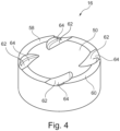
- Figure 4 shows the piston 16 in a perspective view. From this view it can be seen that the piston 16 in addition to the Figure 3 already visible depression 50 has recesses 62 designed as valve pockets. The recesses 62 serve as a mechanical safety device 64 to prevent a collision of the valves 26, 28 with the piston 16.
- Figure 5 shows the combustion chamber 20, in particular the combustion chamber volume 21 in a plan view, wherein the piston 16 is shown transparently.
- the piston squish surfaces 58, 60 are aligned with the squish surface 34 of the cylinder head 14 assigned to the exhaust side, in particular the piston squish surfaces 58, 60 at least partially cover the squish surfaces 32, 34 of the cylinder head 14.
- the piston squish surfaces 58, 60 can be smaller in area than the squish surfaces 32, 34 of the cylinder head 14.
- both the tumble generated and the turbulent kinetic energy of the sucked-in mixture are maintained for as long as possible due to the geometry of the combustion chamber 20, whereby a high combustion speed can be achieved, so that a The initial flame emanating from the spark plug 30 can spread quickly in the mixture. This increases the efficiency of the internal combustion engine 10 accordingly.
- the geometry of the combustion chamber 20 required for this purpose is achieved, among other things, by the active region 41 of the combustion chamber roof 21, which is essentially edge-free and interacts with the recess 50 in the piston 16.
- combustion chamber roof 21 In order to form the combustion chamber roof 21 in this way, it is (exclusively) machined.
Landscapes
- Engineering & Computer Science (AREA)
- Chemical & Material Sciences (AREA)
- Combustion & Propulsion (AREA)
- Mechanical Engineering (AREA)
- General Engineering & Computer Science (AREA)
- Physics & Mathematics (AREA)
- Fluid Mechanics (AREA)
- Combustion Methods Of Internal-Combustion Engines (AREA)
- Cylinder Crankcases Of Internal Combustion Engines (AREA)
Description
- Die vorliegende Erfindung betrifft einen Verbrennungsmotor für ein Kraftfahrzeug.
- Ein Verbrennungsmotor weist üblicherweise wenigstens einen Zylinder, einen Zylinderkopf und einen in dem Zylinder beweglich gelagerten Kolben auf. Diese Elemente begrenzen zusammen einen Brennraum des Verbrennungsmotors, in dem ein Gemisch verbrannt wird, das mindestens aus Luft und Kraftstoff besteht.
- Während eines Verbrennungsprozesses bewegt sich der Kolben zwischen einem oberen Maximalpunkt und einem unteren Maximalpunkt auf und ab, die auch als oberer und unterer Totpunkt bezeichnet werden. Bei einer Aufwärtsbewegung des Kolbens, insbesondere einer Bewegung des Kolbens in Richtung des Zylinderkopfes, kann das Gemisch im Brennraum verdichtet werden. Wenn der Kolben den oberen Totpunkt erreicht hat, entzündet eine in dem Zylinderkopf angeordnete Zündkerze durch Erzeugen einer Initialflamme das Gemisch.
- Um eine möglichst schnelle und effiziente Verbrennung des Gemisches zu erreichen, ist es von Vorteil, wenn das Gemisch eine möglichst hohe turbulente kinetische Energie (TKE) aufweist. Die turbulente kinetische Energie ergibt sich aus dem Strömungsverhalten des Gemisches und wird maßgeblich durch die Geometrie des Brennraums beeinflusst.
- Die
WO 2016/070291 A1 beschreibt eine Brennkammergeometrie, wobei in einem Brennraumdach der Brennkammer Wölbungen vorgesehen sind, die sich in einen Bereich zwischen einem Einlassventilsitz und einem Auslassventilsitz hinein erstrecken. - Die
JP 2001059422 A - Die
DE 10 2014 009 993 A1 beschreibt ein Bauteil für eine Verbrennungskraftmaschine, das durch ein hochfestes Material verstärkt ist, welches mittels Laserschweißens aufgebracht ist. - Die
EP 3 617 473 A1 offenbart eine Geometrie einer Brennkammer für einen Motor, der durch eine Bodenfläche eines Kolbens und ein Brennraumdach begrenzt ist, wobei im Brennraumdach Quetschflächen vorgesehen sind. - Die
US 6,502,540 B1 beschreibt ebenfalls eine Geometrie einer Brennkammer für einen Motor, wobei in einem Brennraumdach parabolisch gewölbte Bereiche vorgesehen sind. - Es ist daher eine Aufgabe der vorliegenden Erfindung, einen Verbrennungsmotor für ein Kraftfahrzeug mit einem optimierten Brennraum anzugeben.
- Diese Aufgabe wird erfindungsgemäß gelöst durch einen Verbrennungsmotor für ein Kraftfahrzeug, mit wenigstens einem Zylinder, einem Zylinderkopf und einem in dem Zylinder beweglich gelagerten Kolben, der eine Brennraumseite hat, die mit dem Zylinderkopf und dem Zylinder einen Brennraum begrenzt, wobei der Zylinderkopf ein Brennraumdach aufweist, in dem mindestens zwei Ventilsitze für mindestens ein Einlassventil und mindestens ein Auslassventil vorgesehen sind, und wobei das Brennraumdach zwei zwischen jeweils einem Ventilsitz für ein Einlassventil und einem Ventilsitz für ein Auslassventil angeordnete, vom Brennraum weg gerichtete, gewölbte Zylinderkopfabschnitte aufweist. Der Zylinderkopf weist lediglich an zwei sich gegenüberliegenden Randabschnitten Quetschflächen in Form von Kreisflächenabschnitten auf, wobei die Quetschflächen jeweils durch eine von zwei parallel zueinander verlaufenden Übergängen im Zylinderkopf begrenzt werden, und wobei die Quetschflächen einer Einlassseite und einer Auslassseite des Zylinderkopfs zugeordnet sind, wobei die der Einlassseite zugeordnete Quetschfläche eine größere Fläche aufweist als die der Auslassseite zugeordnete Quetschfläche.
- Durch die gewölbten, vom Brennraum weg gerichteten Zylinderkopfabschnitte kann das Brennraumdach eine annähernd halbkugelförmige Geometrie aufweisen. Dadurch kann eine besonders vorteilhafte Brennraumgeometrie seitens des Zylinderkopfes erreicht werden. Aufgrund dessen lässt sich das Strömungsverhalten des Gemisches beim Ansaugprozess vorteilhaft beeinflussen.
- Insbesondere ergibt sich eine hinsichtlich des Verbrennungsprozesses besonders günstige, insbesondere kugelförmige, Gestalt des Brennraums. Die beiden gewölbten Zylinderkopfabschnitte liegen somit beide zwischen der Ein-und der Auslassseite des Zylinderkopfes, sodass sie beide einen in etwa gleichen Anteil an der Verbesserung des Strömungsverhaltens haben.
- Gemäß einer Ausführungsform ist ein aktiver Bereich des Brennraumdachs weitestgehend kantenfrei ausgebildet. Der aktive Bereich des Brennraumdachs ist der Bereich, der im Wesentlichen die halbkugelförmige Geometrie des Brennraumdachs ausmacht. Durch die kantenfreie Ausbildung des Brennraumdachs wird insbesondere die Tumbleströmung des Gemisches nicht gestört. Die turbulente kinetische Energie des Luft-Kraftstoff-Gemischs kann somit während der Kompression erzeugt und optimal aufrechterhalten werden.
- Durch die hohe turbulente kinetische Energie lässt sich eine hohe Brenngeschwindigkeit erreichen, sodass sich eine Initialflamme besonders schnell im Gemisch ausbreiten kann. Die hohe Brenngeschwindigkeit führt zudem dazu, dass ein sich während eines Verbrennungszyklus im Brennraum befindliches Gemisch möglichst vollständig verbrannt wird und nahezu kein unverbrannter Kraftstoff im Brennraum verbleibt.
- Insgesamt werden mit dem erfindungsgemäßen Verbrennungsmotor ein besonders guter thermodynamischer Wirkungsgrad und ein reduzierter Verbrauch erreicht.
- Das Brennraumdach ist vorzugsweise vollständig spanend hergestellt worden. Dadurch ist die Reproduzierbarkeit des Brennraumdachs verbessert, da eine spanende Bearbeitung geringeren Fertigungstoleranzen unterliegt als ein Gießprozess. Insbesondere ist hierdurch der weitestgehend kantenfreie aktive Bereich, der wiederum die halbkugelförmige Geometrie zur Folge hat, mit geringen Streuungen darstellbar.
- Der Kolben weist vorzugsweise eine zu einer Kolbenachse rotationssymmetrische, insbesondere linsenförmige, Vertiefung auf, wobei ein Durchmesser der Vertiefung kleiner ist als ein Gesamtdurchmesser des Kolbens. Die Vertiefung lässt zu, dass sich eine Strömung optimal entwickelt, um (bereits beim Einströmen) eine Tumblebewegung im Brennraum zu generieren. Insofern unterstützt die Vertiefung die Aufrechterhaltung der turbulenten kinetischen Energie zum Zeitpunkt der Verbrennung. Die Vertiefung hat zudem ebenso wie das Brennraumdach einen Einfluss auf den Brennraum und somit auf das Verdichtungsverhältnis des Verbrennungsmotors.
- Die Vertiefung des Kolbens weist in ihrem Mittelpunkt vorzugsweise eine Tiefe zwischen 0,2 mm und 10 mm auf, insbesondere zwischen 0,5 mm und 8 mm. Diese Tiefe hat sich als besonders vorteilhaft hinsichtlich der Ladungsbewegung und Flammenausbreitung herausgestellt. Üblicherweise wird die Tiefe der Vertiefung in Kombination mit dem Brennraumdach entsprechend einem vorgegebenen Verdichtungsverhältnis des Verbrennungsmotors festgelegt. Das Verdichtungsverhältnis entspricht dem Verhältnis des gesamten Brennraums vor der Verdichtung, wenn sich der Kolben in dem unteren Totpunkt befindet, zum verbliebenen Raum nach der Verdichtung, wenn sich der Kolben im oberen Totpunkt befindet.
- Eine projizierte Fläche der Vertiefung hat an der Stirnseite, also der Brennraumseite, des Kolbens vorzugsweise einen Flächenanteil von 70 % bis 80 % des Kolbens. Diese Geometrie gewährleistet einen entsprechend hohen flächenmäßigen Anteil der Vertiefung und deren Einfluss auf den gesamten Brennraum entsprechend.
- Die Vertiefung kann zusammen mit dem Brennraumdach, insbesondere mit dem aktiven Bereich des Brennraumdachs, ein annähernd kugelförmiges Volumen einschließen, das als Brennraum dient. Dies begünstigt die Flammenausbreitung im Brennraum, was zu einer besonders effizienten Verbrennung führt.
- Die Zündkerze ist vorzugsweise außermittig im Zylinderkopf angeordnet. Dies ist bedingt durch den Aufbau des Brennraums, insbesondere durch die Anordnung von Ventilen im Zylinderkopf und durch die Anordnung eines Injektors. Wenn Luft oder ein Gemisch, das zumindest Luft und Kraftstoff umfasst, über ein Einlassventil in den Brennraum einströmt, wird es üblicherweise in Richtung der Auslassseite des Brennraums beschleunigt.
- Eine geringe Strömungsgeschwindigkeit im Bereich der Zündkerze ist vorteilhaft, da sich eine Initialflamme bei einer geringen Strömungsgeschwindigkeit besonders gut ausbreiten kann. Sofern die Strömungsgeschwindigkeit zu hoch ist, kann der Zündfunke verweht und die entsprechende Flamme gelöscht werden, wodurch das Gemisch unzureichend oder gar nicht entflammt werden würde, was die Effizienz des Verbrennungsprozesses negativ beeinflusst.
- Der Kolben weist vorzugsweise an seiner Brennraumseite zum Zylinderkopf korrespondierende Kolbenquetschflächen auf. Insbesondere weist der Kolben zwei Kolbenquetschflächen auf, die sich in Bezug auf eine Längsachse des Kolbens radial gegenüberliegen. In einer alternativen Ausführungsform können die Kolbenquetschflächen kleiner sein als die Quetschflächen des Zylinderkopfes. Dies entspricht einem vergrößerten Durchmesser der Vertiefung.
- Die Kolbenquetschflächen sind vorzugsweise teilkreisförmig ausgebildet, insbesondere kreisabschnittförmig beziehungsweise bogenförmig.
- Die der Auslassseite des Zylinderkopfes zugeordnete Kolbenquetschfläche entspricht hinsichtlich der Flächengröße annähernd der entsprechenden Quetschfläche des Zylinderkopfes. Die der Einlassseite des Zylinderkopfes zugeordnete Kolbenquetschfläche kann flächenmäßig kleiner ausgebildet sein als die entsprechende Quetschfläche des Zylinderkopfes.
- Vorzugsweise ist im Brennraumdach neben einem Ventilsitz eine Maskierung parallel zur Ventilachse des Einlassventils angeordnet, die eine Höhe zwischen 2 mm und 3,5 mm aufweist. Mittels der Maskierung wird erreicht, dass sich insbesondere bei kleinen Ventilhüben eine Überströmung der Einlassventile ergibt, was eine Tumble-Bewegung des Gemisches zur Folge hat. Durch die Tumble-Bewegung wird das Turbulenzniveau erhöht.
- Der Kolben weist vorzugsweise an seiner Brennraumseite mindestens zwei als Ventiltaschen ausgebildete Aussparungen auf. Die Ventiltaschen dienen als mechanische Absicherung, um eine Kollision zwischen Ventil und Kolben zu vermeiden.
- Weitere Merkmale und Vorteile der Erfindung ergeben sich aus der nachfolgenden Beschreibung und aus den nachfolgenden Zeichnungen, auf die Bezug genommen wird. In den Zeichnungen zeigen:
-
Figur 1 schematisch einen erfindungsgemäßen Verbrennungsmotor, -
Figur 2 ein Brennraumvolumen eines erfindungsgemäßen Verbrennungsmotors, -
Figur 3 einen Kolben eines erfindungsgemäßen Verbrennungsmotors in einer Schnittansicht, -
Figur 4 den Kolben ausFigur 3 in einer Perspektivansicht, und -
Figur 5 den Brennraum eines erfindungsgemäßen Verbrennungsmotors in einer Draufsicht, wobei der dem Brennraum zugeordnete Kolben transparent dargestellt ist. -
Figur 1 zeigt schematisch einen Verbrennungsmotor 10 mit einem Zylinder 12, einem Zylinderkopf 14 und einem im Zylinder 12 beweglich gelagerten Kolben 16. - Der Kolben 16 hat eine Brennraumseite 18, die zusammen mit dem Zylinderkopf 14 und dem Zylinder 12 einen Brennraum 20 des Verbrennungsmotors 10 begrenzt, wobei der Zylinderkopf 14 ein zum Brennraum 20 hin gerichtetes Brennraumdach 21 aufweist. Im Zylinderkopf 14, insbesondere im Brennraumdach 21, sind Ventilsitze 22, 24 für mindestens ein Einlassventil 26 bzw. Auslassventil 28 sowie eine Zündkerze 30 angeordnet. Die Zündkerze 30 ist insbesondere außermittig angeordnet.
- Die in
Figur 1 schematisch dargestellten Elemente werden in den nachfolgenden Figuren detailliert erläutert. - Die allgemeine Funktionsweise von Verbrennungsmotoren ist aus dem Stand der Technik hinreichend bekannt, daher soll an dieser Stelle nicht weiter darauf eingegangen werden, da es nachfolgend auf die Geometrie des Zylinderkopfs 14 ankommt, insbesondere die Geometrie der zum Brennraum 20 gerichteten Seite des Zylinderkopfs 14.
-
Figur 2 zeigt ein Brennraumvolumen 31 eines erfindungsgemäßen Verbrennungsmotors 10 in einem Zustand, in dem sich der Kolben 16 im oberen Maximalpunkt befindet. Das Brennraumvolumen 31 wird durch den Zylinderkopf 14, insbesondere dessen Brennraumdach 21, zusammen mit dem Zylinder 12 und dem Kolben 16 begrenzt. - Somit zeigt
Figur 2 im Wesentlichen einen Negativabdruck des Zylinderkopfes 14, insbesondere dessen Brennraumdach 21, und des Kolbens 16. - Der Zylinderkopf 14, insbesondere das Brennraumdach 21, hat in einer Draufsicht eine runde Außengeometrie und weist im Wesentlichen fünf zueinander abgewinkelte Flächen 32, 34, 36, 38, 40 auf. Die Flächen 38, 40 und 36, 40 sind jeweils abgerundet zueinander, um scharfe Kanten in einem aktiven Bereich 41 des Brennraumdachs 21 an den entsprechenden Übergängen der Flächen 36 - 40 zu vermeiden. Der aktive Bereich 41 des Brennraumdachs 21 umfasst vorzugsweise unter anderem die Flächen 36, 38, 40.
- Bei den seitlich am Zylinderkopf 14 angeordneten Flächen 32, 34 handelt es sich jeweils um eine Quetschfläche. Die Form der Quetschflächen 32, 34 entspricht der Form eines Kreisabschnitts, wobei die Quetschflächen 32, 34 jeweils durch einen von zwei parallel zueinander verlaufenden Übergängen 42, 44 nach (radial) innen begrenzt sind, wohingegen der Außenrand einer Zylinderlaufbahn die Quetschflächen 32, 34 nach (radial) außen begrenzt. Die beiden Quetschflächen 32, 34 sind demnach in gegenüberliegenden Randabschnitten des Zylinderkopfes 14 angeordnet.
- Die Übergänge 42, 44 sind jeweils zwischen den Quetschflächen 32, 34 und den anschließenden Flächen 36, 38 vorgesehen, die sich ausgehend von den Quetschflächen 32, 34 zum Mittelpunkt des Zylinderkopfes 14 erstrecken und Teil des aktiven Bereichs 41 sind. Die Übergänge 42, 44 weisen einen unterschiedlichen Abstand zum Mittelpunkt des Zylinderkopfes 14 auf.
- In der gezeigten Ausführungsform ist die der Einlassseite, also den Einlassventilen 26, zugeordnete Quetschfläche 32 flächenmäßig größer als die der Auslassseite zugeordnete Quetschfläche 34, also die den Auslassventilen 28 zugeordnete Quetschfläche 34.
- Zwischen den Ventilsitzen 22, 24, insbesondere zwischen jeweils einem Ventilsitz 22 für ein Einlassventil 26 und einem Ventilsitz 24 für ein Auslassventil 28, sind jeweils im Zylinderkopf 14 gewölbte Abschnitte 46, 47 angeordnet. Die gewölbten Abschnitte 46, 47 sind ebenfalls Teil des aktiven Bereichs 41 des Brennraumdachs 21, wobei sie derart gewölbt sind, dass ihre Wölbung vom Brennraum 20 wegweist.
- Durch die gewölbten Abschnitte 46, 47, insbesondere ihre Wölbung, kann das Brennraumdach 21 eine im Wesentlichen halbkugelförmige Geometrie aufweisen. Dadurch wird eine Flammenausbreitung im Brennraum 20 begünstigt, was wiederum zu einer thermodynamisch optimalen Verbrennung führt, wie nachfolgend noch erläutert wird.
- Der Zylinderkopf 14, insbesondere das Brennraumdach 21, weist insgesamt vier Ventilsitze 22, 24 für zwei Einlassventile 26 und zwei Auslassventile 28 auf. Im Brennraumdach 21 ist angrenzend an den Ventilsitz 22 der Einlassventile 26 jeweils eine Maskierung 48 parallel zur Ventilachse angeordnet, welche eine Höhe zwischen 2 mm und 3,5 mm aufweist. Die Maskierung 48 sorgt für eine hohe Tumble-Bewegung des über die Einlassventile 26 einströmenden Gemischs, was zu einer Erhöhung der turbulenten kinetischen Energie des Gemisches und damit zu einer gesteigerten Brenngeschwindigkeit und einer optimierten Flammenausbreitung führt.
-
Figur 3 zeigt einen Kolben 16 in einer Schnittansicht, der beispielsweise in einem Druckgussverfahren hergestellt worden ist. - An der Brennraumseite 18 des Kolbens 16, die zusammen mit dem Zylinder 12 und dem Zylinderkopf 14, insbesondere dem Brennraumdach 21, den Brennraum 20 des Verbrennungsmotors 10 begrenzt, ist eine Vertiefung 50 eingebracht, die rotationssymmetrisch und linsenförmig ist. Die Vertiefung 50 weist eine Bodenfläche 52 sowie eine Höhe h zwischen 0,5 mm und 8 mm auf. Die Vertiefung 50 des Kolbens 16 ist rotationssymmetrisch bezüglich einer Längsachse 54 ausgebildet.
- Die Wölbung der Vertiefung 50 entspricht beispielsweise im Wesentlichen der Wölbung der gewölbten Abschnitte 46, 47 des Zylinderkopfes 14, wobei sie entgegengesetzt ausgerichtet ist. Dadurch kann der Brennraum 20 möglichst symmetrisch ausgebildet sein. Durch das Zusammenspiel des aktiven Bereichs 41, insbesondere der gewölbten Abschnitte 46, 47 und der linsenförmigen Vertiefung 50 ist der Brennraum 20 annähernd kugelförmig, was optimal hinsichtlich der Verbrennung ist.
- Der beim Einströmen des Gemisches erzeugte Tumble wird aufgrund dieser Geometrie des Brennraums 20 unterstützt und aufrechterhalten.
- Der Durchmesser d der Vertiefung 50 ist kleiner als der Gesamtdurchmesser D des Kolbens 16, wodurch ein umlaufener Steg 56 gebildet wird, der die Vertiefung 50 radial umgibt. Ein Teil des umlaufenden Stegs 56 bildet Kolbenquetschflächen 58, 60 des Kolbens 16, die in Zusammenhang mit
Figur 4 näher beschrieben werden. Der Gesamtdurchmesser D des Kolbens 16 entspricht näherungsweise dem Innendurchmesser des Zylinders 12. - Generell lässt sich (zusätzlich) über die Tiefe der Vertiefung 50 das Verdichtungsverhältnis des Verbrennungsmotors 10 einstellen, sofern die mechanischen Randbedingungen bzw. Begrenzungen berücksichtigt werden, beispielsweise hinsichtlich der Stabilität des Kolbens 16.
-
Figur 4 zeigt den Kolben 16 in einer Perspektivansicht. Aus dieser Ansicht geht hervor, dass der Kolben 16 zusätzlich zu der inFigur 3 bereits erkennbaren Vertiefung 50 als Ventiltaschen ausgebildete Aussparungen 62 aufweist. Die Aussparungen 62 dienen als eine mechanische Sicherung 64, um eine Kollision der Ventile 26, 28 mit dem Kolben 16 zu vermeiden. -
Figur 5 zeigt den Brennraum 20, insbesondere das Brennraumvolumen 21 in einer Draufsicht, wobei der Kolben 16 transparent dargestellt ist. - Die Kolbenquetschflächen 58, 60 sind an der der Auslassseite zugeordneten Quetschfläche 34 des Zylinderkopfes 14 ausgerichtet, insbesondere überdecken die Kolbenquetschflächen 58, 60 die Quetschflächen 32, 34 des Zylinderkopfes 14 zumindest teilweise. In einer alternativen Ausführungsform können die Kolbenquetschflächen 58, 60 flächenmäßig kleiner sein als die Quetschflächen 32, 24 des Zylinderkopfes 14.
- Wie bereits erläutert, werden sowohl der erzeugte Tumble als auch die turbulente kinetische Energie des eingesaugten Gemisches aufgrund der Geometrie des Brennraums 20 möglichst lange aufrechterhalten, wodurch sich eine hohe Brenngeschwindigkeit erreichen lässt, sodass sich eine von der Zündkerze 30 ausgehende Initialflamme schnell im Gemisch ausbreiten kann. Hierdurch steigt die Effizienz des Verbrennungsmotors 10 entsprechend.
- Die hierfür notwendige Geometrie des Brennraums 20 wird unter anderem durch den im Wesentlichen kantenfrei ausgebildeten aktiven Bereich 41 des Brennraumdachs 21 erreicht, der mit der Vertiefung 50 im Kolben 16 zusammenwirkt.
- Um das Brennraumdach 21 derart auszubilden, ist dieses (ausschließlich) spanend bearbeitet.
Claims (8)
- Verbrennungsmotor (10) für ein Kraftfahrzeug, mit wenigstens einem Zylinder (12), einem Zylinderkopf (14) und einem in dem Zylinder (12) beweglich gelagerten Kolben (16), der eine Brennraumseite (18) hat, die mit dem Zylinderkopf (14) und dem Zylinder (12) einen Brennraum (20) begrenzt, wobei der Zylinderkopf (14) ein Brennraumdach (21) aufweist, in dem mindestens zwei Ventilsitze (22, 24) für mindestens ein Einlassventil (26) und mindestens ein Auslassventil (28) vorgesehen sind, und wobei das Brennraumdach (21) zwei zwischen jeweils einem Ventilsitz (22) für ein Einlassventil (26) und einem Ventilsitz (24) für ein Auslassventil (28) angeordnete, vom Brennraum (20) weg gerichtete, gewölbte Zylinderkopfabschnitte (46, 47) aufweist, wobei der Zylinderkopf (14) lediglich an zwei sich gegenüberliegenden Randabschnitten Quetschflächen (32, 34) in Form von Kreisflächenabschnitten aufweist, dadurch gekennzeichnet, dass die Quetschflächen jeweils durch eine von zwei parallel zueinander verlaufenden Übergängen (42, 44) im Zylinderkopf (14) begrenzt werden, wobei die Quetschflächen (32, 34) einer Einlassseite und einer Auslassseite des Zylinderkopfs (14) zugeordnet sind, wobei die der Einlassseite zugeordnete Quetschfläche (32) eine größere Fläche aufweist als die der Auslassseite zugeordnete Quetschfläche (34).
- Verbrennungsmotor (10) nach Anspruch 1, dadurch gekennzeichnet, dass ein aktiver Bereich (41) des Brennraumdachs (21) im Wesentlichen kantenfrei ausgebildet ist.
- Verbrennungsmotor (10) nach einem der vorhergehenden Ansprüche, dadurch gekennzeichnet, dass das Brennraumdach (21) vollständig spanend hergestellt worden ist.
- Verbrennungsmotor (10) nach einem der vorherigen Ansprüche, dadurch gekennzeichnet, dass der Kolben (16) eine zu einer Kolbenachse (54) rotationssymmetrische, insbesondere linsenförmige, Vertiefung (50) aufweist, wobei ein Durchmesser (d) der Vertiefung (50) kleiner ist als ein Gesamtdurchmesser (D) des Kolbens (16).
- Verbrennungsmotor (10) nach Anspruch 4, dadurch gekennzeichnet, dass die Vertiefung (50) in ihrem Mittelpunkt eine Tiefe zwischen 0,2 mm und 10 mm aufweist, insbesondere zwischen 0,5 mm und 8 mm.
- Verbrennungsmotor (10) nach einem der Ansprüche 4 bis 5, dadurch gekennzeichnet, dass die Vertiefung (50) zusammen mit dem Brennraumdach (21), insbesondere mit dem aktiven Bereich (41) des Brennraumdachs (21), ein annähernd kugelförmiges Volumen einschließt.
- Verbrennungsmotor (10) nach einem der vorhergehenden Ansprüche, dadurch gekennzeichnet, dass im Brennraumdach (21) neben einem Ventilsitz (22) eine Maskierung (48) parallel zur Ventilachse des Einlassventils (26) angeordnet ist, die eine Höhe zwischen 2 mm und 3,5 mm aufweist.
- Verbrennungsmotor (10) nach einem der vorhergehenden Ansprüche, dadurch gekennzeichnet, dass zwei gewölbte Zylinderkopfabschnitte (46, 47) vorgesehen sind, die jeweils zwischen zwei Ventilsitzen (22, 24) angeordnet sind, die einem Einlassventil (26) und ein Auslassventil (28) zugeordnet sind.
Applications Claiming Priority (2)
| Application Number | Priority Date | Filing Date | Title |
|---|---|---|---|
| DE102017216996.6A DE102017216996B3 (de) | 2017-09-26 | 2017-09-26 | Verbrennungsmotor |
| PCT/EP2018/071538 WO2019063178A1 (de) | 2017-09-26 | 2018-08-08 | Verbrennungsmotor |
Publications (2)
| Publication Number | Publication Date |
|---|---|
| EP3688293A1 EP3688293A1 (de) | 2020-08-05 |
| EP3688293B1 true EP3688293B1 (de) | 2025-01-15 |
Family
ID=63207739
Family Applications (1)
| Application Number | Title | Priority Date | Filing Date |
|---|---|---|---|
| EP18755170.0A Active EP3688293B1 (de) | 2017-09-26 | 2018-08-08 | Verbrennungsmotor |
Country Status (5)
| Country | Link |
|---|---|
| US (1) | US11125181B2 (de) |
| EP (1) | EP3688293B1 (de) |
| CN (1) | CN110799736B (de) |
| DE (1) | DE102017216996B3 (de) |
| WO (1) | WO2019063178A1 (de) |
Families Citing this family (2)
| Publication number | Priority date | Publication date | Assignee | Title |
|---|---|---|---|---|
| WO2022199833A1 (en) * | 2021-03-26 | 2022-09-29 | Jaguar Land Rover Limited | A cylinder head for a lean-burn gasoline engine |
| US12404802B2 (en) * | 2023-04-13 | 2025-09-02 | Saudi Arabian Oil Company | Combustion chamber for high performance H2 direct injection engine |
Citations (2)
| Publication number | Priority date | Publication date | Assignee | Title |
|---|---|---|---|---|
| US6502540B1 (en) * | 1999-01-19 | 2003-01-07 | Alvin J. Smith | Internal combustion engine gas flow control |
| EP3617473A1 (de) * | 2017-06-02 | 2020-03-04 | Mazda Motor Corporation | Brennkammerstruktur für motoren |
Family Cites Families (36)
| Publication number | Priority date | Publication date | Assignee | Title |
|---|---|---|---|---|
| FR2282043A1 (fr) * | 1974-08-12 | 1976-03-12 | Yamaha Motor Co Ltd | Moteur a combustion interne |
| JPS5142309U (de) * | 1974-09-24 | 1976-03-29 | ||
| US4162661A (en) * | 1977-02-25 | 1979-07-31 | Toyota Jidosha Kogyo Kabushiki Kaisha | Internal combustion engine with combustion chambers which create a squish and swirl of an air-fuel mixture |
| JPS5851131B2 (ja) * | 1978-07-20 | 1983-11-15 | トヨタ自動車株式会社 | 内燃機関の燃焼室構造 |
| US4635591A (en) * | 1984-10-11 | 1987-01-13 | Hledin Alexander S | Internal-combustion engines |
| JPS6415423A (en) * | 1987-07-10 | 1989-01-19 | Isuzu Motors Ltd | Combustion chamber for internal combustion engine |
| JPH01219310A (ja) * | 1988-02-29 | 1989-09-01 | Suzuki Motor Co Ltd | 四サイクルエンジン |
| AT402535B (de) | 1990-02-23 | 1997-06-25 | Avl Verbrennungskraft Messtech | Brennkraftmaschine mit zumindest zwei einlassventilen je motorzylinder |
| JPH0642352A (ja) | 1992-07-22 | 1994-02-15 | Fuji Heavy Ind Ltd | 内燃機関の燃焼室構造 |
| KR100304232B1 (ko) * | 1997-05-20 | 2001-10-19 | 하나와 요시카즈 | 성층급기연소및균질급기연소가가능한관내분사식가솔린엔진 |
| JP2001003754A (ja) * | 1999-06-16 | 2001-01-09 | Nissan Motor Co Ltd | 筒内噴射式内燃機関 |
| JP2001059422A (ja) * | 1999-08-19 | 2001-03-06 | Daihatsu Motor Co Ltd | 火花点火式の四弁型内燃機関の構造 |
| JP3835171B2 (ja) * | 2001-01-12 | 2006-10-18 | 日産自動車株式会社 | 内燃機関のピストン |
| US6745745B2 (en) * | 2002-02-22 | 2004-06-08 | General Motors Corporation | Combustion chamber for reverse tumble spark ignition direct injection engine |
| CA2442336C (en) * | 2003-09-30 | 2006-09-19 | Westport Research Inc. | Method and apparatus for providing for high egr gaseous-fuelled direct injection internal combustion engine |
| TWI290191B (en) * | 2003-10-24 | 2007-11-21 | Mitsubishi Motors Corp | Combustion chamber structure in an internal combustion engine |
| DE102004005727A1 (de) * | 2004-02-05 | 2005-09-01 | Robert Bosch Gmbh | Brennstoffeinspritzsystem |
| US7438039B2 (en) * | 2004-02-06 | 2008-10-21 | Electro-Motive Diesel, Inc. | Large-bore, medium-speed diesel engine having piston crown bowl with acute re-entrant angle |
| JP4552773B2 (ja) * | 2005-06-27 | 2010-09-29 | 日産自動車株式会社 | エンジンの燃焼室構造 |
| DE102005035296B4 (de) | 2005-07-28 | 2007-10-04 | Audi Ag | Verfahren zur Herstellung von Hubkolbenmaschinen sowie Hubkolbenmaschine |
| WO2008092294A1 (fr) * | 2007-01-17 | 2008-08-07 | Dennis Tien Lam | Piston de moteur à combustion interne |
| JP4254865B2 (ja) * | 2007-01-29 | 2009-04-15 | トヨタ自動車株式会社 | 内燃機関用ピストン及びそのピストンが適用された内燃機関 |
| JP2009041397A (ja) * | 2007-08-07 | 2009-02-26 | Nissan Motor Co Ltd | 複数点火エンジンの燃焼室構造 |
| CN101220782A (zh) * | 2007-12-13 | 2008-07-16 | 奇瑞汽车有限公司 | 发动机缸盖气道口的加工方法 |
| CN201246211Y (zh) * | 2008-08-27 | 2009-05-27 | 重庆宗申发动机制造有限公司 | 一种摩托车发动机燃烧室 |
| CN101929411B (zh) * | 2009-06-23 | 2016-08-17 | 百佳车辆有限公司 | 改进的内燃机及包含该内燃机的车辆 |
| CN201546800U (zh) * | 2009-09-25 | 2010-08-11 | 上汽通用五菱汽车股份有限公司 | 小排量发动机的燃烧室 |
| CN201891519U (zh) * | 2010-10-26 | 2011-07-06 | 王允文 | 由点燃式内燃机改装成的压燃式内燃机 |
| JP2013204472A (ja) * | 2012-03-27 | 2013-10-07 | Mitsubishi Motors Corp | エンジンのピストン |
| CN103362634B (zh) * | 2012-03-30 | 2015-11-25 | 本田技研工业株式会社 | 内燃机 |
| CN104295395A (zh) * | 2013-07-16 | 2015-01-21 | 磊擎动力技术有限公司 | 活塞机构总成 |
| CN204099153U (zh) * | 2014-05-08 | 2015-01-14 | 黄荣嵘 | 臂杆活塞联动式空气压缩机 |
| DE102014009993A1 (de) * | 2014-07-05 | 2014-12-24 | Daimler Ag | Bauteil für eine Verbrennungskraftmaschine sowie Verfahren und Vorrichtung zu dessen Herstellung |
| CA2967005C (en) * | 2014-11-06 | 2023-05-02 | Westport Power Inc. | Combustion chamber geometry |
| JP2016125447A (ja) * | 2015-01-07 | 2016-07-11 | トヨタ自動車株式会社 | 内燃機関 |
| CN204851420U (zh) * | 2015-06-15 | 2015-12-09 | 华晨汽车集团控股有限公司 | 一种增压发动机缸盖燃烧室结构 |
-
2017
- 2017-09-26 DE DE102017216996.6A patent/DE102017216996B3/de active Active
-
2018
- 2018-08-08 EP EP18755170.0A patent/EP3688293B1/de active Active
- 2018-08-08 WO PCT/EP2018/071538 patent/WO2019063178A1/de not_active Ceased
- 2018-08-08 CN CN201880042513.5A patent/CN110799736B/zh active Active
-
2020
- 2020-02-07 US US16/784,710 patent/US11125181B2/en active Active
Patent Citations (2)
| Publication number | Priority date | Publication date | Assignee | Title |
|---|---|---|---|---|
| US6502540B1 (en) * | 1999-01-19 | 2003-01-07 | Alvin J. Smith | Internal combustion engine gas flow control |
| EP3617473A1 (de) * | 2017-06-02 | 2020-03-04 | Mazda Motor Corporation | Brennkammerstruktur für motoren |
Also Published As
| Publication number | Publication date |
|---|---|
| CN110799736B (zh) | 2021-10-29 |
| US20200173392A1 (en) | 2020-06-04 |
| CN110799736A (zh) | 2020-02-14 |
| DE102017216996B3 (de) | 2019-01-17 |
| US11125181B2 (en) | 2021-09-21 |
| WO2019063178A1 (de) | 2019-04-04 |
| EP3688293A1 (de) | 2020-08-05 |
Similar Documents
| Publication | Publication Date | Title |
|---|---|---|
| DE10392141B4 (de) | Kolben für Verbrennungsmotor | |
| DE102005002389B4 (de) | Fahrzeug-Kolben-Brennkraftmaschine mit angepasster Mulde | |
| DE102010030692A1 (de) | Glühkerzenanordnung in einem Dieselmotor | |
| DE2755531A1 (de) | Brennkraftmaschine | |
| EP0598941A1 (de) | Kolben mit Brennraummulde für eine Brennkraftmaschine | |
| DE4441092A1 (de) | Ventil zur Einbringung von Kraftstoff oder Kraftstoff-Luft-Gemisch | |
| DE2654258A1 (de) | Verbrennungsmotor mit hilfsbrennkammer | |
| DE2934615A1 (de) | Selbstzuendende 4-takt-hubkolbenbrennkraftmaschine. | |
| DE102013009413B4 (de) | Zündvorrichtung zum Zünden eines Gasgemisches einer mit Gas betriebenen Brennkraftmaschine | |
| DE2550495A1 (de) | Ventilgesteuerte verbrennungskraftmaschine | |
| DE102017216996B3 (de) | Verbrennungsmotor | |
| DE202016106470U1 (de) | Texturierter Kolben | |
| WO2010081491A1 (de) | Kleiner direkt-einspritzender dieselmotor | |
| DE60309093T2 (de) | Brennkammer für eine mehrzylindrige, selbstzündende Brennkraftmaschine, insbesondere für einen direkteingespritzen Dieselmotor sowie zugehöriger Motor | |
| DE102018133550B4 (de) | Verbrennungskraftmaschine | |
| DE60220429T2 (de) | Verbrennungsmotor mit fremdzündung und direkter kraftstoffeinspritzung, umfassend ein system zur direkteinspritzung unter sehr hohem druck | |
| DE2038048C3 (de) | Luftverdichtende, direkteinspritzende Brennkraftmaschine | |
| EP1792065B1 (de) | Brennkraftmaschine | |
| DE1259634B (de) | Gas-Ottomotor | |
| EP2060737A1 (de) | Zylinderanordnung für eine Hubkolbenbrennkraftmaschine, sowie Hubkolbenbrennkraftmaschine | |
| DE3805009A1 (de) | Kolben fuer dieselmotoren | |
| DE69806480T2 (de) | Brennkraftmaschine mit fremdzündung | |
| DE102011106803A1 (de) | Brennkraftmaschine | |
| DE112023000437T5 (de) | Kolbenmulde für erdgasmotoren mit niedriger kompression für verbesserte verbrennungsstabilität | |
| DE102017216995B4 (de) | Kolben für einen Verbrennungsmotor, Verfahren zur Herstellung eines Kolbens und Verbrennungsmotor |
Legal Events
| Date | Code | Title | Description |
|---|---|---|---|
| STAA | Information on the status of an ep patent application or granted ep patent |
Free format text: STATUS: UNKNOWN |
|
| STAA | Information on the status of an ep patent application or granted ep patent |
Free format text: STATUS: THE INTERNATIONAL PUBLICATION HAS BEEN MADE |
|
| PUAI | Public reference made under article 153(3) epc to a published international application that has entered the european phase |
Free format text: ORIGINAL CODE: 0009012 |
|
| STAA | Information on the status of an ep patent application or granted ep patent |
Free format text: STATUS: REQUEST FOR EXAMINATION WAS MADE |
|
| 17P | Request for examination filed |
Effective date: 20200326 |
|
| AK | Designated contracting states |
Kind code of ref document: A1 Designated state(s): AL AT BE BG CH CY CZ DE DK EE ES FI FR GB GR HR HU IE IS IT LI LT LU LV MC MK MT NL NO PL PT RO RS SE SI SK SM TR |
|
| AX | Request for extension of the european patent |
Extension state: BA ME |
|
| DAV | Request for validation of the european patent (deleted) | ||
| DAX | Request for extension of the european patent (deleted) | ||
| STAA | Information on the status of an ep patent application or granted ep patent |
Free format text: STATUS: EXAMINATION IS IN PROGRESS |
|
| 17Q | First examination report despatched |
Effective date: 20220311 |
|
| P01 | Opt-out of the competence of the unified patent court (upc) registered |
Effective date: 20230502 |
|
| RIC1 | Information provided on ipc code assigned before grant |
Ipc: F02B 23/06 20060101AFI20240801BHEP |
|
| GRAP | Despatch of communication of intention to grant a patent |
Free format text: ORIGINAL CODE: EPIDOSNIGR1 |
|
| STAA | Information on the status of an ep patent application or granted ep patent |
Free format text: STATUS: GRANT OF PATENT IS INTENDED |
|
| INTG | Intention to grant announced |
Effective date: 20241008 |
|
| GRAS | Grant fee paid |
Free format text: ORIGINAL CODE: EPIDOSNIGR3 |
|
| GRAA | (expected) grant |
Free format text: ORIGINAL CODE: 0009210 |
|
| STAA | Information on the status of an ep patent application or granted ep patent |
Free format text: STATUS: THE PATENT HAS BEEN GRANTED |
|
| P02 | Opt-out of the competence of the unified patent court (upc) changed |
Free format text: CASE NUMBER: APP_64289/2024 Effective date: 20241204 |
|
| AK | Designated contracting states |
Kind code of ref document: B1 Designated state(s): AL AT BE BG CH CY CZ DE DK EE ES FI FR GB GR HR HU IE IS IT LI LT LU LV MC MK MT NL NO PL PT RO RS SE SI SK SM TR |
|
| REG | Reference to a national code |
Ref country code: CH Ref legal event code: EP Ref country code: GB Ref legal event code: FG4D Free format text: NOT ENGLISH |
|
| REG | Reference to a national code |
Ref country code: DE Ref legal event code: R096 Ref document number: 502018015499 Country of ref document: DE |
|
| REG | Reference to a national code |
Ref country code: IE Ref legal event code: FG4D Free format text: LANGUAGE OF EP DOCUMENT: GERMAN |
|
| REG | Reference to a national code |
Ref country code: NL Ref legal event code: MP Effective date: 20250115 |
|
| PG25 | Lapsed in a contracting state [announced via postgrant information from national office to epo] |
Ref country code: NL Free format text: LAPSE BECAUSE OF FAILURE TO SUBMIT A TRANSLATION OF THE DESCRIPTION OR TO PAY THE FEE WITHIN THE PRESCRIBED TIME-LIMIT Effective date: 20250115 |
|
| PG25 | Lapsed in a contracting state [announced via postgrant information from national office to epo] |
Ref country code: RS Free format text: LAPSE BECAUSE OF FAILURE TO SUBMIT A TRANSLATION OF THE DESCRIPTION OR TO PAY THE FEE WITHIN THE PRESCRIBED TIME-LIMIT Effective date: 20250415 |
|
| PG25 | Lapsed in a contracting state [announced via postgrant information from national office to epo] |
Ref country code: FI Free format text: LAPSE BECAUSE OF FAILURE TO SUBMIT A TRANSLATION OF THE DESCRIPTION OR TO PAY THE FEE WITHIN THE PRESCRIBED TIME-LIMIT Effective date: 20250115 |
|
| PG25 | Lapsed in a contracting state [announced via postgrant information from national office to epo] |
Ref country code: PL Free format text: LAPSE BECAUSE OF FAILURE TO SUBMIT A TRANSLATION OF THE DESCRIPTION OR TO PAY THE FEE WITHIN THE PRESCRIBED TIME-LIMIT Effective date: 20250115 |
|
| PG25 | Lapsed in a contracting state [announced via postgrant information from national office to epo] |
Ref country code: ES Free format text: LAPSE BECAUSE OF FAILURE TO SUBMIT A TRANSLATION OF THE DESCRIPTION OR TO PAY THE FEE WITHIN THE PRESCRIBED TIME-LIMIT Effective date: 20250115 |
|
| REG | Reference to a national code |
Ref country code: LT Ref legal event code: MG9D |
|
| PG25 | Lapsed in a contracting state [announced via postgrant information from national office to epo] |
Ref country code: IS Free format text: LAPSE BECAUSE OF FAILURE TO SUBMIT A TRANSLATION OF THE DESCRIPTION OR TO PAY THE FEE WITHIN THE PRESCRIBED TIME-LIMIT Effective date: 20250515 Ref country code: NO Free format text: LAPSE BECAUSE OF FAILURE TO SUBMIT A TRANSLATION OF THE DESCRIPTION OR TO PAY THE FEE WITHIN THE PRESCRIBED TIME-LIMIT Effective date: 20250415 |
|
| PG25 | Lapsed in a contracting state [announced via postgrant information from national office to epo] |
Ref country code: HR Free format text: LAPSE BECAUSE OF FAILURE TO SUBMIT A TRANSLATION OF THE DESCRIPTION OR TO PAY THE FEE WITHIN THE PRESCRIBED TIME-LIMIT Effective date: 20250115 |
|
| PG25 | Lapsed in a contracting state [announced via postgrant information from national office to epo] |
Ref country code: PT Free format text: LAPSE BECAUSE OF FAILURE TO SUBMIT A TRANSLATION OF THE DESCRIPTION OR TO PAY THE FEE WITHIN THE PRESCRIBED TIME-LIMIT Effective date: 20250515 Ref country code: LV Free format text: LAPSE BECAUSE OF FAILURE TO SUBMIT A TRANSLATION OF THE DESCRIPTION OR TO PAY THE FEE WITHIN THE PRESCRIBED TIME-LIMIT Effective date: 20250115 |
|
| PG25 | Lapsed in a contracting state [announced via postgrant information from national office to epo] |
Ref country code: GR Free format text: LAPSE BECAUSE OF FAILURE TO SUBMIT A TRANSLATION OF THE DESCRIPTION OR TO PAY THE FEE WITHIN THE PRESCRIBED TIME-LIMIT Effective date: 20250416 Ref country code: BG Free format text: LAPSE BECAUSE OF FAILURE TO SUBMIT A TRANSLATION OF THE DESCRIPTION OR TO PAY THE FEE WITHIN THE PRESCRIBED TIME-LIMIT Effective date: 20250115 |
|
| PG25 | Lapsed in a contracting state [announced via postgrant information from national office to epo] |
Ref country code: SE Free format text: LAPSE BECAUSE OF FAILURE TO SUBMIT A TRANSLATION OF THE DESCRIPTION OR TO PAY THE FEE WITHIN THE PRESCRIBED TIME-LIMIT Effective date: 20250115 |
|
| PG25 | Lapsed in a contracting state [announced via postgrant information from national office to epo] |
Ref country code: SM Free format text: LAPSE BECAUSE OF FAILURE TO SUBMIT A TRANSLATION OF THE DESCRIPTION OR TO PAY THE FEE WITHIN THE PRESCRIBED TIME-LIMIT Effective date: 20250115 |
|
| PG25 | Lapsed in a contracting state [announced via postgrant information from national office to epo] |
Ref country code: DK Free format text: LAPSE BECAUSE OF FAILURE TO SUBMIT A TRANSLATION OF THE DESCRIPTION OR TO PAY THE FEE WITHIN THE PRESCRIBED TIME-LIMIT Effective date: 20250115 |
|
| PGFP | Annual fee paid to national office [announced via postgrant information from national office to epo] |
Ref country code: DE Payment date: 20250731 Year of fee payment: 8 |
|
| PGFP | Annual fee paid to national office [announced via postgrant information from national office to epo] |
Ref country code: IT Payment date: 20250829 Year of fee payment: 8 |
|
| PGFP | Annual fee paid to national office [announced via postgrant information from national office to epo] |
Ref country code: GB Payment date: 20250822 Year of fee payment: 8 |
|
| REG | Reference to a national code |
Ref country code: DE Ref legal event code: R097 Ref document number: 502018015499 Country of ref document: DE |
|
| PGFP | Annual fee paid to national office [announced via postgrant information from national office to epo] |
Ref country code: FR Payment date: 20250827 Year of fee payment: 8 |
|
| PG25 | Lapsed in a contracting state [announced via postgrant information from national office to epo] |
Ref country code: EE Free format text: LAPSE BECAUSE OF FAILURE TO SUBMIT A TRANSLATION OF THE DESCRIPTION OR TO PAY THE FEE WITHIN THE PRESCRIBED TIME-LIMIT Effective date: 20250115 Ref country code: CZ Free format text: LAPSE BECAUSE OF FAILURE TO SUBMIT A TRANSLATION OF THE DESCRIPTION OR TO PAY THE FEE WITHIN THE PRESCRIBED TIME-LIMIT Effective date: 20250115 |
|
| PG25 | Lapsed in a contracting state [announced via postgrant information from national office to epo] |
Ref country code: RO Free format text: LAPSE BECAUSE OF FAILURE TO SUBMIT A TRANSLATION OF THE DESCRIPTION OR TO PAY THE FEE WITHIN THE PRESCRIBED TIME-LIMIT Effective date: 20250115 |
|
| PG25 | Lapsed in a contracting state [announced via postgrant information from national office to epo] |
Ref country code: SK Free format text: LAPSE BECAUSE OF FAILURE TO SUBMIT A TRANSLATION OF THE DESCRIPTION OR TO PAY THE FEE WITHIN THE PRESCRIBED TIME-LIMIT Effective date: 20250115 |
|
| PLBE | No opposition filed within time limit |
Free format text: ORIGINAL CODE: 0009261 |
|
| STAA | Information on the status of an ep patent application or granted ep patent |
Free format text: STATUS: NO OPPOSITION FILED WITHIN TIME LIMIT |
|
| REG | Reference to a national code |
Ref country code: CH Ref legal event code: L10 Free format text: ST27 STATUS EVENT CODE: U-0-0-L10-L00 (AS PROVIDED BY THE NATIONAL OFFICE) Effective date: 20251126 |
|
| 26N | No opposition filed |
Effective date: 20251016 |
|
| REG | Reference to a national code |
Ref country code: CH Ref legal event code: H13 Free format text: ST27 STATUS EVENT CODE: U-0-0-H10-H13 (AS PROVIDED BY THE NATIONAL OFFICE) Effective date: 20260324 |
|
| PG25 | Lapsed in a contracting state [announced via postgrant information from national office to epo] |
Ref country code: MC Free format text: LAPSE BECAUSE OF FAILURE TO SUBMIT A TRANSLATION OF THE DESCRIPTION OR TO PAY THE FEE WITHIN THE PRESCRIBED TIME-LIMIT Effective date: 20250115 |
|
| PG25 | Lapsed in a contracting state [announced via postgrant information from national office to epo] |
Ref country code: LU Free format text: LAPSE BECAUSE OF NON-PAYMENT OF DUE FEES Effective date: 20250808 |
|
| PG25 | Lapsed in a contracting state [announced via postgrant information from national office to epo] |
Ref country code: CH Free format text: LAPSE BECAUSE OF NON-PAYMENT OF DUE FEES Effective date: 20250831 |