EP3686649B1 - Prismatische ar-anzeigevorrichtung - Google Patents
Prismatische ar-anzeigevorrichtung Download PDFInfo
- Publication number
- EP3686649B1 EP3686649B1 EP17872891.1A EP17872891A EP3686649B1 EP 3686649 B1 EP3686649 B1 EP 3686649B1 EP 17872891 A EP17872891 A EP 17872891A EP 3686649 B1 EP3686649 B1 EP 3686649B1
- Authority
- EP
- European Patent Office
- Prior art keywords
- light
- prism
- lens
- beam splitting
- light incident
- Prior art date
- Legal status (The legal status is an assumption and is not a legal conclusion. Google has not performed a legal analysis and makes no representation as to the accuracy of the status listed.)
- Active
Links
Images


Classifications
-
- G—PHYSICS
- G02—OPTICS
- G02B—OPTICAL ELEMENTS, SYSTEMS OR APPARATUS
- G02B30/00—Optical systems or apparatus for producing three-dimensional [3D] effects, e.g. stereoscopic images
-
- G—PHYSICS
- G02—OPTICS
- G02B—OPTICAL ELEMENTS, SYSTEMS OR APPARATUS
- G02B1/00—Optical elements characterised by the material of which they are made; Optical coatings for optical elements
- G02B1/10—Optical coatings produced by application to, or surface treatment of, optical elements
-
- G—PHYSICS
- G02—OPTICS
- G02B—OPTICAL ELEMENTS, SYSTEMS OR APPARATUS
- G02B27/00—Optical systems or apparatus not provided for by any of the groups G02B1/00 - G02B26/00, G02B30/00
- G02B27/01—Head-up displays
- G02B27/0101—Head-up displays characterised by optical features
-
- G—PHYSICS
- G02—OPTICS
- G02B—OPTICAL ELEMENTS, SYSTEMS OR APPARATUS
- G02B27/00—Optical systems or apparatus not provided for by any of the groups G02B1/00 - G02B26/00, G02B30/00
- G02B27/01—Head-up displays
- G02B27/017—Head mounted
- G02B27/0172—Head mounted characterised by optical features
-
- G—PHYSICS
- G02—OPTICS
- G02B—OPTICAL ELEMENTS, SYSTEMS OR APPARATUS
- G02B27/00—Optical systems or apparatus not provided for by any of the groups G02B1/00 - G02B26/00, G02B30/00
- G02B27/10—Beam splitting or combining systems
- G02B27/1006—Beam splitting or combining systems for splitting or combining different wavelengths
- G02B27/102—Beam splitting or combining systems for splitting or combining different wavelengths for generating a colour image from monochromatic image signal sources
- G02B27/1026—Beam splitting or combining systems for splitting or combining different wavelengths for generating a colour image from monochromatic image signal sources for use with reflective spatial light modulators
- G02B27/1033—Beam splitting or combining systems for splitting or combining different wavelengths for generating a colour image from monochromatic image signal sources for use with reflective spatial light modulators having a single light modulator for all colour channels
-
- G—PHYSICS
- G02—OPTICS
- G02B—OPTICAL ELEMENTS, SYSTEMS OR APPARATUS
- G02B27/00—Optical systems or apparatus not provided for by any of the groups G02B1/00 - G02B26/00, G02B30/00
- G02B27/10—Beam splitting or combining systems
- G02B27/1066—Beam splitting or combining systems for enhancing image performance, like resolution, pixel numbers, dual magnifications or dynamic range, by tiling, slicing or overlapping fields of view
-
- G—PHYSICS
- G02—OPTICS
- G02B—OPTICAL ELEMENTS, SYSTEMS OR APPARATUS
- G02B27/00—Optical systems or apparatus not provided for by any of the groups G02B1/00 - G02B26/00, G02B30/00
- G02B27/10—Beam splitting or combining systems
- G02B27/14—Beam splitting or combining systems operating by reflection only
- G02B27/144—Beam splitting or combining systems operating by reflection only using partially transparent surfaces without spectral selectivity
-
- G—PHYSICS
- G02—OPTICS
- G02B—OPTICAL ELEMENTS, SYSTEMS OR APPARATUS
- G02B27/00—Optical systems or apparatus not provided for by any of the groups G02B1/00 - G02B26/00, G02B30/00
- G02B27/28—Optical systems or apparatus not provided for by any of the groups G02B1/00 - G02B26/00, G02B30/00 for polarising
- G02B27/283—Optical systems or apparatus not provided for by any of the groups G02B1/00 - G02B26/00, G02B30/00 for polarising used for beam splitting or combining
-
- G—PHYSICS
- G02—OPTICS
- G02B—OPTICAL ELEMENTS, SYSTEMS OR APPARATUS
- G02B5/00—Optical elements other than lenses
- G02B5/04—Prisms
- G02B5/045—Prism arrays
-
- G—PHYSICS
- G02—OPTICS
- G02B—OPTICAL ELEMENTS, SYSTEMS OR APPARATUS
- G02B5/00—Optical elements other than lenses
- G02B5/30—Polarising elements
-
- G—PHYSICS
- G02—OPTICS
- G02B—OPTICAL ELEMENTS, SYSTEMS OR APPARATUS
- G02B27/00—Optical systems or apparatus not provided for by any of the groups G02B1/00 - G02B26/00, G02B30/00
- G02B27/01—Head-up displays
- G02B27/0101—Head-up displays characterised by optical features
- G02B2027/0112—Head-up displays characterised by optical features comprising device for genereting colour display
- G02B2027/0114—Head-up displays characterised by optical features comprising device for genereting colour display comprising dichroic elements
-
- G—PHYSICS
- G02—OPTICS
- G02B—OPTICAL ELEMENTS, SYSTEMS OR APPARATUS
- G02B27/00—Optical systems or apparatus not provided for by any of the groups G02B1/00 - G02B26/00, G02B30/00
- G02B27/01—Head-up displays
- G02B27/0101—Head-up displays characterised by optical features
- G02B2027/0112—Head-up displays characterised by optical features comprising device for genereting colour display
- G02B2027/0116—Head-up displays characterised by optical features comprising device for genereting colour display comprising devices for correcting chromatic aberration
Definitions
- the present disclosure relates to AR, and more particularly, to a prismatic AR display device.
- AR augmented reality
- This kind of technology superimposes virtual information onto real-world scenes so as to achieve the "seamless" integration of the real-world information with the virtual-world one.
- the AR technology is required to use the imaging technology and the beam-splitting and combining technology.
- the imaging optical path and the beam-splitting and combining optical path are realized by a single one beam splitting prism.
- virtual images seen by human eyes may have a relatively large color difference and a poor definition.
- Prior art document D1 discloses an intelligent helmet binocular display system for electric power inspection and a realization method of intelligent helmet binocular display system, where, according to the method, a binocular imaging optical subsystem and a sequential logical circuit based on an FPGA (Field Programmable Gate Array) are designed; an invented intelligent helmet binocular enhanced reality display system comprises image acquisition, data conversion, caching, storage, protocol conversion and an interface; intelligent helmet binocular imaging enhanced reality display for the electric power inspection is realized (see ABSTRACT of D1).
- FPGA Field Programmable Gate Array
- a plurality of aspects of the present disclosure provide a prismatic AR display device for reducing the color difference of virtual images and improving the definition of aliased images viewed by human eyes.
- the present invention provides a prismatic AR display device as defined in claim 1.
- the first single lens is a positive lens.
- first light incident surface and/or the second light incident surface are/is plated with an anti-reflection film.
- the display device further comprises a polarization element, wherein the polarization element is located on a light emergent side of a second light emergent surface of the beam splitting prism, and a polarization direction of the polarization element is perpendicular to the polarization direction of the PBS; the second light emergent surface is opposite to the first light incident surface.
- first light incident surface and/or the second light incident surface are/is a concave surface.
- the beam splitting prism comprises a first prism and a second prism that are sequentially arranged
- the beam splitting prism comprises a second prism and a first prism that are sequentially arranged
- the first light emergent surface is a concave surface that is concentric with the second light incident surface and has the same curvature radius as the latter.
- the LCOS lighting apparatus comprises a concavo-convex lens and a light source device that are sequentially arranged along the second axis, wherein a first surface of the concavo-convex lens close to the light source device is a concave spherical surface, and a second surface of the concavo-convex lens close to the PBS is a convex spherical surface; light emitted by the light source device is converged to the PBS via the concavo-convex lens, and polarized by the PBS, and then enters the LCOS display chip in the form of an orthogonal linearly polarized light.
- the LCOS lighting apparatus comprises an aspherical positive lens arranged on the second axis and located between the concavo-convex lens and the PBS, wherein the aspherical positive lens is used for uniformly refracting the light emitted from the light source device and refracted by the concavo-convex lens to the PBS so that the refracted light is polarized by the PBS and then enters the LCOS display chip.
- the imaging optical path comprises the double cemented lens and the first single lens that are coaxially arranged in order, and the beam-splitting and combining optical path is realized by the beam splitting prism.
- the double cemented lens can correct the color difference generated by the imaging optical path and the beam-splitting and combining optical path while conducting imaging on the virtual image light emitted by the LCOS display chip, and thus the color difference of the virtual images may be reduced and the definition of the aliased images viewed by human eyes may be improved.
- some of the embodiments of the present disclosure provide a prismatic AR display device as shown in the following drawings.
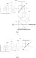
- FIG. 2 is a schematic diagram illustrating the structure of a prismatic AR display device provided by some embodiments of the present disclosure.
- the prismatic AR display device comprises: an LCOS display chip 100, a polarization beam splitter (PBS) 101, a double cemented lens 102, a first single lens 103 and a beam splitting prism 104 which are sequentially arranged along a first axis, and LCOS lighting apparatus 105 which is arranged on a second axis perpendicular to the first axis and close to the PBS 101.
- both the first axis and the second axis may be perpendicular to a light incident surface of the PBS 101 and pass through the geometric center point of the PBS 101, and the two are perpendicular to each other.
- the double cemented lens 102 may be formed by bonding a low-dispersion crown glass positive lens with a high-dispersion flint glass negative lens, and the negative lens in the double cemented lens 102 is close to the PBS 101, and the positive lens is close to the first single lens 103.
- the double cemented lens 102 can not only eliminate the color difference generated in optical paths, but also deflect light of large divergence angle transmitted by the PBS 101 into that of small divergence angle to be propagated, which can improve the light collecting efficiency of the AR display device.
- the first single lens 103 may be a positive lens.
- the first single lens 103 is used to cooperate with the double cemented lens 102 to conduct imaging, and share focal power in the optical path system to optimize the optical path structure.
- the material of the first single lens 103 may be different from that of the double cemented lens 102.
- the first single lens 103 is neither a flint glass lens nor a crown glass lens. As such, it can further eliminate the color difference produced in optical paths, which can improve the definition of virtual images viewed by human eyes in the end.
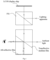
- the beam splitting prism 104 comprises two light incident surfaces, two light emergent surfaces and one beam splitting surface, and the beam splitting surface may be realized by the transflective medium film.
- a first light incident surface Si1 of the beam splitting prism 104 is close to the first single lens 103, and its optical axis coincides with that of the first single lens 103; an optical axis of a second light incident surface Si2 of the beam splitting prism 104 is perpendicular to that of the first light incident surface Si1, and the second light incident surface Si2 is opposite to a first light emergent surface Se1.
- the LCOS display chip 100 cited herein is a kind of display chip that can't emit light independently, which needs to be illuminated by polarized light to exhibit pictures of different gray scales and colors.
- the PBS 101 is used to cooperate with the LCOS lighting apparatus 105 to generate linearly polarized light to achieve illumination of the LCOS display chip 100.
- the virtual image light emitted by the LCOS display chip 100 enters the first single lens 103 where it is refracted to the beam splitting prism 104 by the first single lens 103; then, it is combined, on a beam splitting surface of the beam splitting prism 104, with ambient light from the second light incident surface Si2 of the beam splitting prism 104; thereafter, the combined light is transmitted to human eyes from the first light emergent surface Se1 of the beam splitting prism 104.
- the virtual images superimposed with real ambient images can be viewed by human eyes from the light emergent side of the first light emergent surface Se1.
- the imaging optical path comprises the double cemented lens 102 and the first single lens 103 that are coaxially arranged in order, and the beam-splitting and combining optical path is realized by the beam splitting prism 104.
- the double cemented lens 102 can correct the color difference generated by the imaging optical path and the beam-splitting and combining optical path while conducting imaging on the virtual image light emitted by the LCOS display chip 100, which reduces the color difference of virtual images, which can improve the definition of aliased images viewed by human eyes.
- the imaging optical path formed by the double cemented lens 102 and the first single lens 103 comprises, in total, five optical surfaces having certain curvature radiuses. This ensures that the imaging optical path has a sufficiently large field angle, and that this field angle may be adjusted according to imaging requirements.
- the beam splitting prism 104 may be equivalently regarded as a parallel plate glass having a certain thickness for shortening optical paths to optimize the structure of the display device.
- the beam splitting prism 104 comprises a first prism 1041 and a second prism 1042 that are sequentially arranged, wherein a slant facet of the first prism 1041 is cemented to that of the second prism 1042, and a cemented surface is plated thereon with a transflective medium film to form a beam splitting surface of the beam splitting prism 104.
- the first light incident surface Si1 may be a surface on the first prism 1041 which is close to the first single lens 103 and whose optical axis coincides with that of the first single lens 103;
- the first light emergent surface Se1 may be a surface on the first prism 1041 whose optical axis is perpendicular to that of the first single lens 103;
- the second light incident surface Si2 may be a surface on the second prism 1042 whose optical axis is perpendicular to that of the first single lens 103.
- Virtual image light refracted by the first single lens 103 is incident on the beam splitting surface through the first light incident surface Si1 on the first prism 1041, which is then reflected to the first light emergent surface Se1 on the first prism 1041 via the beam splitting surface; at the same time, ambient light is incident on the beam splitting surface through the second light incident surface Si2 on the second prism 1042, which is then transmitted to the first light emergent surface Se1 on the first prism 1041 via the beam splitting surface.
- virtual-real aliasing images can be viewed by human eyes from the light emergent side of the first light emergent surface Se1.
- the virtual image light refracted by the first single lens 103 is required to pass through the beam splitting surface of the beam splitting prism 104 only once before it reaches human eyes, and thus, its optical efficiency is 50%.
- the virtual image light passes through the beam splitting surface of the beam splitting prism twice, and thus, its optical efficiency is only 25%. Therefore, with respect to the related art, the present disclosure can greatly improve the optical efficiency of virtual images during their imaging, which, under the condition of enabling human eyes to view virtual images of equal brightness, reduces the power consumption required by the LCOS lighting apparatus for illuminating the LCOS display chip 100.
- the beam splitting prism 104 comprises a second prism 1042 and a first prism 1041 that are sequentially arranged, wherein a slant facet of the second prism 1042 is cemented to that of the first prism 1041, and a cemented surface is plated thereon with a transflective medium film for forming a beam splitting surface of the beam splitting prism 104.
- the first light incident surface Si1 may be a surface on the second prism 1042 which is close to the first single lens 103 and whose optical axis coincides with that of the first single lens 103;
- the second light incident surface Si2 may be a surface on the second prism 1042 whose optical axis is perpendicular to that of the first single lens 103, and the second light incident surface Si2 is a convex surface and plated with the transflective medium film;
- the first light emergent surface Se1 may be a surface on the first prism 1041 whose optical axis is perpendicular to that of the first single lens 103.
- virtual image light refracted by the first single lens 103 is incident on the beam splitting surface through the first light incident surface Si1 on the second prism 1042; then, it is reflected to the second light incident surface Si2 on the second prism 1042 via the beam splitting surface; thereafter, this light is reflected to the beam splitting surface by the second light incident surface Si2, and then transmitted to the first light emergent surface Se1 on the first prism 1041 via the beam splitting surface.
- ambient light is incident on the beam splitting surface through the second light incident surface Si2 on the second prism 1042, which is then transmitted to the first light emergent surface Se1 on the first prism 1041 via the beam splitting surface.
- virtual-real aliasing images can be viewed by human eyes from the light emergent side of the first light emergent surface Se1.
- the second light incident surface Si2 is a convex surface and plated with the transflective medium film, which can collimate light incident thereon to form amplified images.
- the virtual image light after collimation is more concentrated in energy, which can improve the definition of virtual images viewed by a user.
- the first light emergent surface Se1 is a concave surface concentric with the second light incident surface Si2, and its curvature radius is the same as that of the second light incident surface Si2, such that effective regions of the beam splitting prism 104 are equal in thickness. As such, the distortion of ambient light is reduced, and the quality of ambient light viewed by human eyes is improved.
- the PBS 101 may be cemented by a pair of high-precision rectangular prisms.
- a ramped surface of one of the rectangular prisms is plated thereon with a polarization beam splitting medium film capable of splitting an incident non-polarized light into two linearly polarized light beams perpendicular to each other.
- the horizontally polarized light (P light) passes through the film completely, while the vertically polarized light (S light) is reflected out at an angle of 45 degrees.
- the emergent directions of the S polarized light and the P polarized light form an angle of 90 degrees.
- the LCOS display chip 100 and the LCOS lighting apparatus 105 may be arranged on two adjacent sides of the PBS 101.
- the LCOS display chip 100 is arranged on the first axis
- the LCOS lighting apparatus 105 is arranged on the second axis.
- the LCOS lighting apparatus 105 comprises a concavo-convex lens 1051 and a light source device 1052 that are sequentially arranged along the second axis.
- Non-polarized light of large divergence angle emitted by the light source device 1052 first enters the concavo-convex lens 1051 where it is refracted, via the concavo-convex lens 1051, into light with small divergence angle; then, such light with small divergence angle enters the PBS 101, and is polarized by the polarization beam splitting medium film of the PBS 101; thereafter, one of the linearly polarized light beams may illuminate the LCOS display chip 100 so that the LCOS display chip 100 may exhibit pictures of different gray scales and colors.
- the virtual image light emitted by the LCOS display chip 100 should be construed as the light reflected by the LCOS display chip 100 through the above illumination process, and detailed description thereof will be omitted.
- a first surface S11 of the concavo-convex lens 1051 close to the light source device 1052 is a concave spherical surface
- a second surface S12 away from the light source device 1052 is a convex spherical surface.
- the second surface S12 is a convex spherical surface in the shape of nearly a semi-spherical surface, such that when the curvature radius is determined, the second surface S12 has a maximum numerical aperture.
- the light flux of the second surface S12 is increased so as to propagate light refracted thereon by the first surface S11 as much as possible.
- the second surface S12 can endow light emitted out of the concavo-convex lens 1051 with a smaller divergence angle to control the angle of the illuminative light spot reaching the LCOS display chip 100 to be within a reasonable range.
- the curvature radius of the second surface S12 may be designed to be twice that of the first surface S11.
- the adoption of the concavo-convex lens 1051 can achieve a high lighting efficiency.
- the light source device 1052 gives out light inhomogeneously, thus leading to poor uniformity in the light illuminated on the display area of the LCOS display chip 100.
- the present disclosure also sets forth an LCOS lighting apparatus as shown in Figure 4 .
- this apparatus further comprises an aspherical positive lens 1053.
- the aspherical positive lens 1053 is located between the concavo-convex lens 1051 and the PBS 101, and coaxial with the concavo-convex lens 1051.
- the light emitted by the light source device 1052 may be deflected, by the concavo-convex lens 1051, into that of small divergence angle before it is incident on the aspherical positive lens 1053.
- the aspherical positive lens 1053 can uniformly refract the light emitted by the light source device 1052 and refracted thereon by the concavo-convex lens 1051 to the PBS 101 where it is polarized by the PBS 101 and then enters the LCOS display chip 100.
- the aspherical positive lens 1053 has a curvature radius continuously changes from the center to the edge, and its focal power is positive. As such, the direction of each emergent light ray can be accurately controlled, such that light may reach specified positions on the target plane upon being deflected. In this manner, illuminative light spots are ensured to be distributed fairly uniformly on the LCOS display chip.
- the first light incident surface Si1 and/or the second light incident surface Si2 may be plated with an anti-reflection film. If the first light incident surface Si1 is plated thereon with an anti-reflection film, the intensity of the virtual image light incident on the first light incident surface Si1 can be increased, such that the virtual images viewed by human eyes are clearer. Similarly, if the second light incident surface Si2 is plated thereon with an anti-reflection film, the intensity of ambient light incident on the second light incident surface Si2 can be increased, such that the true ambient images viewed by human eyes are clearer.
- the first light incident surface Si1 and/or the second light incident surface Si2 may be a concave surface to enhance its light collecting capability.
- the first light incident surface Si1 is a concave surface, the first light incident surface Si1 can propagate the virtual image light emitted by the LCOS display chip 100 at a high light collecting efficiency even though the display area of the LCOS display chip 100 is augmented.
- the transflective medium film in the beam splitting prism 104 can transmit part of the virtual image light incident through the first light incident surface Si1 to the second light emergent surface Se2 of the beam splitting prism 104, wherein the second light emergent surface Se2 is the surface in the beam splitting prism 104 opposite to the first light incident surface Si1.
- the light emergent side of the second light emergent surface Se2 is unobstructed, which is likely to let out virtual images, thus undermining privacy of a user.
- the prismatic AR display device may further comprise a polarization element 106.
- the polarization element 106 is located on the light emergent side of the second light emergent surface Se2, and the polarization direction of the polarization element 106 is perpendicular to that of the PBS 101.
- the polarization element 106 may eliminate the polarized virtual image light transmitted out of the second light emergent surface Se2, which avoids letting out virtual images viewed by a user, thus protecting the privacy of the user and improving user experience.
- the polarization element 106 may be an optical element separate from the beam splitting prism 104, e.g., a polarization plate. In some embodiments, the polarization element 106 may be designed integrally with the beam splitting prism. For example, the second light emergent surface Se2 of the beam splitting prism 104 may be plated with a polarization medium film to further optimize the volume of the display device while achieving light elimination.
- some embodiments of the present disclosure provides prismatic AR display apparatus comprising any one of the prismatic AR display devices described in the above embodiments. Accordingly, this apparatus has such advantages as small imaging color difference, large field angle and high optical efficiency.
Landscapes
- Physics & Mathematics (AREA)
- General Physics & Mathematics (AREA)
- Optics & Photonics (AREA)
- Spectroscopy & Molecular Physics (AREA)
- Optical Elements Other Than Lenses (AREA)
- Surface Treatment Of Optical Elements (AREA)
- Lenses (AREA)
- Polarising Elements (AREA)
Claims (10)
- Prismatische AR-Anzeigevorrichtung, dadurch gekennzeichnet, dass sie Folgendes umfasst:einen LCOS-Anzeigechip, ein Polarisations-Strahlteilerprisma PBS, eine doppelt verkittete Linse, eine erste Einzellinse sowie ein Strahlteilerprisma, die nacheinander entlang einer ersten Achse angeordnet sind, und eine LCOS-Beleuchtungsvorrichtung, die an einer zweiten Achse senkrecht zur ersten Achse angeordnet ist und nahe an dem PBS liegt,wobei die doppelt verkittete Linse eine positive Linse und eine negative Linse umfasst, wobei die negative Linse nahe an dem PBS und die positive Linse nahe an der ersten Einzellinse liegt,eine erste Lichteintrittsfläche des Strahlteilerprismas nahe an der ersten Einzellinse liegt, und ihre optische Achse mit der optischen Achse der ersten Einzellinse übereinstimmt, die optische Achse einer zweiten Lichteintrittsfläche des Strahlteilerprismas senkrecht zur optischen Achse der ersten Lichteintrittsfläche steht, und die zweite Lichteintrittsfläche einer ersten Lichtaustrittsfläche gegenüberliegt;die LCOS-Beleuchtungsvorrichtung vorgesehen ist, um den LCOS-Anzeigechip so zu beleuchten, dass der LCOS-Anzeigechip virtuelles Bildlicht emittiert; das vom LCOS-Anzeigechip emittierte virtuelle Bildlicht direkt in die doppelt verkittete Linse nach einer Transmission durch das PBS, in die erste Einzellinse nach einer Brechung durch die doppelt verkittete Linse, in das Strahlteilerprisma nach einer Brechung durch die erste Einzellinse gelangt, und an der ersten Lichteintrittsfläche des Strahlteilerprismas es mit einem Umgebungslicht, das von der zweiten Lichteintrittsfläche des Strahlteilerprismas kommt, kombiniert und nach der Kombination von der ersten Lichtaustrittsfläche des Strahlteilerprismas zum menschlichen Auge übertragen wird,wobei das virtuelle Bildlicht, nachdem es durch das PBS transmittiert wurde und bevor es in das Strahlteilerprisma gelangt, fünf optische Flächen mit einem bestimmten Krümmungsradius durchläuft.
- Vorrichtung nach Anspruch 1, dadurch gekennzeichnet, dass die erste Einzellinse eine positive Linse ist und die doppelt verkittete Linse durch Verkitten einer positiven Linse aus Kronenglas mit niedriger Dispersion mit einer negativen Linse aus Flintglas mit hoher Dispersion hergestellt ist, wobei sich das Material der ersten Einzellinse vom Material der doppelt verkitteten Linse unterscheidet.
- Vorrichtung nach Anspruch 1, dadurch gekennzeichnet, dass die erste Lichteintrittsfläche und/oder die zweite Lichteintrittsfläche mit einer Antireflexionsfolie beschichtet sind.
- Vorrichtung nach Anspruch 1, dadurch gekennzeichnet, dass sie ferner ein Polarisationselement umfasst,
wobei sich das Polarisationselement an der Lichtaustrittsseite einer zweiten Lichtaustrittsfläche des Strahlteilerprismas befindet und die Polarisationsrichtung des Polarisationselements senkrecht zur Polarisationsrichtung des PBS steht, wobei die zweite Lichtaustrittsfläche der ersten Lichteintrittsfläche gegenüberliegt. - Vorrichtung nach Anspruch 1, dadurch gekennzeichnet, dass die erste Lichteintrittsfläche und/oder die zweite Lichteintrittsfläche konkave Flächen sind.
- Vorrichtung nach einem der Ansprüche 1 bis 5, dadurch gekennzeichnet, dass das Strahlteilerprisma ein erstes Prisma und ein zweites Prisma umfasst, die nacheinander angeordnet sind,wobei eine schräge Fläche des ersten Prismas mit einer schrägen Fläche des zweiten Prismas verklebt ist, und an der Klebefläche zwischen den beiden schrägen Flächen eine halbdurchlässige, halbreflektierende dielektrische Folie aufgebracht ist, um eine Strahlteilerfläche des Strahlteilerprismas zu bilden;eine Fläche des ersten Prismas, die nahe an der ersten Einzellinse liegt und deren optische Achse mit der optischen Achse der ersten Einzellinse übereinstimmt, die erste Lichteintrittsfläche ist,eine Fläche des ersten Prismas, deren optische Achse senkrecht zur optischen Achse der ersten Einzellinse steht, die erste Lichtaustrittsfläche ist,und eine Fläche des zweiten Prismas, deren optische Achse senkrecht zur optischen Achse der ersten Einzellinse steht, die zweite Lichteintrittsfläche ist.
- Vorrichtung nach einem der Ansprüche 1 bis 4, dadurch gekennzeichnet, dass das Strahlteilerprisma ein zweites Prisma und ein erstes Prisma umfasst, die nacheinander angeordnet sind,wobei eine schräge Fläche des zweiten Prismas mit einer schrägen Fläche des ersten Prismas verklebt ist, und an der Klebefläche zwischen den beiden schrägen Flächen eine halbdurchlässige, halbreflektierende dielektrische Folie aufgebracht ist, um eine Strahlteilerfläche des Strahlteilerprismas zu bilden;eine Fläche des zweiten Prismas, die nahe an der ersten Einzellinse liegt und deren optische Achse mit der optischen Achse der ersten Einzellinse übereinstimmt, die erste Lichteintrittsfläche ist,eine Fläche des zweiten Prismas, deren optische Achse senkrecht zur optischen Achse der ersten Einzellinse steht, die zweite Lichteintrittsfläche ist, wobei die zweite Lichteintrittsfläche eine konvexe Fläche ist und mit einer halbdurchlässigen, halbreflektierenden dielektrischen Folie beschichtet ist,und eine Fläche des ersten Prismas, deren optische Achse senkrecht zur optischen Achse der ersten Einzellinse steht, die erste Lichtaustrittsfläche ist.
- Vorrichtung nach Anspruch 7, dadurch gekennzeichnet, dass die erste Lichtaustrittsfläche eine konkave Fläche ist, die konzentrisch mit der zweiten Lichteintrittsfläche ist und denselben Krümmungsradius aufweist.
- Vorrichtung nach Anspruch 1, dadurch gekennzeichnet, dass die LCOS-Beleuchtungsvorrichtung eine konkav-konvexe Linse und eine Lichtquellenvorrichtung umfasst, die nacheinander entlang der zweiten Achse angeordnet sind,wobei eine erste Fläche der konkav-konvexen Linse nahe der Lichtquellenvorrichtung eine konkave sphärische Fläche ist und eine zweite Fläche nahe dem PBS eine konvexe sphärische Fläche ist,das von der Lichtquellenvorrichtung emittierte Licht durch die konkav-konvexe Linse zum PBS gebündelt wird und als vertikal linear polarisiertes Licht in den LCOS-Anzeigechip gelangt, nachdem es durch den PBS polarisiert wurde.
- Vorrichtung nach Anspruch 9, dadurch gekennzeichnet, dass sie eine asphärische positive Linse umfasst, die an der zweiten Achse und zwischen der konkav-konvexen Linse und dem PBS angeordnet ist,
wobei die asphärische Positivlinse verwendet wird, um das von der Lichtquellenvorrichtung emittierte Licht, das durch der konkav-konvexen Linse gebrochen wird, gleichmäßig zum PBS zu brechen, sodass es in den LCOS-Anzeigechip gelangt, nachdem es durch den PBS polarisiert wurde.
Applications Claiming Priority (2)
| Application Number | Priority Date | Filing Date | Title |
|---|---|---|---|
| CN201710847856.6A CN107422484B (zh) | 2017-09-19 | 2017-09-19 | 棱镜式ar显示装置 |
| PCT/CN2017/104431 WO2019056409A1 (zh) | 2017-09-19 | 2017-09-29 | 棱镜式ar显示装置 |
Publications (4)
| Publication Number | Publication Date |
|---|---|
| EP3686649A1 EP3686649A1 (de) | 2020-07-29 |
| EP3686649A4 EP3686649A4 (de) | 2020-11-25 |
| EP3686649B1 true EP3686649B1 (de) | 2025-01-22 |
| EP3686649C0 EP3686649C0 (de) | 2025-01-22 |
Family
ID=60433604
Family Applications (1)
| Application Number | Title | Priority Date | Filing Date |
|---|---|---|---|
| EP17872891.1A Active EP3686649B1 (de) | 2017-09-19 | 2017-09-29 | Prismatische ar-anzeigevorrichtung |
Country Status (6)
| Country | Link |
|---|---|
| US (1) | US10690912B2 (de) |
| EP (1) | EP3686649B1 (de) |
| JP (1) | JP6909790B2 (de) |
| KR (1) | KR102059760B1 (de) |
| CN (1) | CN107422484B (de) |
| WO (1) | WO2019056409A1 (de) |
Families Citing this family (21)
| Publication number | Priority date | Publication date | Assignee | Title |
|---|---|---|---|---|
| KR102568792B1 (ko) * | 2017-12-04 | 2023-08-21 | 삼성전자주식회사 | 회절 광학 렌즈를 구비한 다중 영상 디스플레이 장치 |
| CN109991744B (zh) | 2018-01-02 | 2020-12-01 | 京东方科技集团股份有限公司 | 显示装置、显示方法及平视显示装置 |
| CN107966821A (zh) | 2018-01-02 | 2018-04-27 | 京东方科技集团股份有限公司 | 增强现实眼镜 |
| CN116149062A (zh) * | 2018-02-12 | 2023-05-23 | 优奈柯恩(北京)科技有限公司 | Ar显示装置和穿戴式ar设备 |
| CN108776390A (zh) * | 2018-06-08 | 2018-11-09 | 施轩杰 | 一种使用非严格分光棱镜的光学显示系统方案 |
| CN108881538B (zh) * | 2018-06-22 | 2024-08-02 | 北京小米移动软件有限公司 | 移动终端 |
| CN108957750A (zh) * | 2018-07-09 | 2018-12-07 | 歌尔科技有限公司 | 光学系统、头戴显示设备及智能眼镜 |
| JP7131145B2 (ja) * | 2018-07-10 | 2022-09-06 | セイコーエプソン株式会社 | ヘッドマウントディスプレイ |
| KR102129669B1 (ko) * | 2018-08-27 | 2020-07-02 | 주식회사 파노비젼 | 전반사 구조를 갖는 투과형 hmd 광학시스템 |
| CN110262038B (zh) * | 2019-06-06 | 2022-06-21 | 歌尔光学科技有限公司 | 光学系统及具有其的虚拟现实设备 |
| CN113892050B (zh) | 2019-07-04 | 2025-01-14 | 三星电子株式会社 | 用于显示增强现实的电子设备和方法 |
| CN110361872A (zh) * | 2019-07-15 | 2019-10-22 | 合肥工业大学 | 一种透视三维显示装置及三维显示系统 |
| CN111158150A (zh) * | 2020-02-10 | 2020-05-15 | Oppo广东移动通信有限公司 | 镜片组件及头戴显示设备 |
| CN111474723A (zh) * | 2020-05-09 | 2020-07-31 | Oppo广东移动通信有限公司 | 显示光学系统及头戴显示设备 |
| CN112346252A (zh) | 2020-11-09 | 2021-02-09 | 京东方科技集团股份有限公司 | 近眼显示装置 |
| CN113064285A (zh) * | 2021-03-29 | 2021-07-02 | 深圳珑璟光电技术有限公司 | 一种偏振分光棱镜和近眼显示系统 |
| KR102603651B1 (ko) * | 2021-05-27 | 2023-11-21 | 유한회사 에픽에이비오닉스 | 이미지의 위치 조절이 가능한 디스플레이모듈 및 이를 포함한 광학장치 |
| CN117192725B (zh) * | 2023-09-27 | 2024-08-27 | 北京创思工贸有限公司 | 一种反射棱镜组的胶合方法 |
| CN117310943B (zh) * | 2023-11-13 | 2025-10-17 | 宁波舜宇奥来技术有限公司 | 投影系统和ar投影装置 |
| CN120195891A (zh) * | 2023-12-22 | 2025-06-24 | 华为技术有限公司 | 透镜模组、显示装置以及增强现实显示设备 |
| US12341948B1 (en) * | 2024-04-09 | 2025-06-24 | DISTANCE TECHNOLOGIES Oy | Compensating for optical combiner curvature |
Family Cites Families (38)
| Publication number | Priority date | Publication date | Assignee | Title |
|---|---|---|---|---|
| JP3473720B2 (ja) * | 1995-02-23 | 2003-12-08 | 株式会社ニコン | 観察光学系および観察方法 |
| JPH1075407A (ja) * | 1996-08-30 | 1998-03-17 | Olympus Optical Co Ltd | 画像表示装置 |
| JP3291448B2 (ja) * | 1997-01-21 | 2002-06-10 | 三洋電機株式会社 | 偏光照明装置及び該偏光照明装置を用いた投写型表示装置 |
| JP3802653B2 (ja) * | 1997-05-21 | 2006-07-26 | オリンパス株式会社 | 立体画像表示装置 |
| JP2002365585A (ja) * | 2001-05-31 | 2002-12-18 | Daeyang E & C Co Ltd | 頭部装着用ディスプレー用光学システム |
| WO2003001275A2 (en) * | 2001-06-21 | 2003-01-03 | Koninklijke Philips Electronics N.V. | Display device |
| US7192139B2 (en) * | 2002-12-04 | 2007-03-20 | Thomson Licensing | High contrast stereoscopic projection system |
| US7290882B2 (en) * | 2004-02-05 | 2007-11-06 | Ocutronics, Llc | Hand held device and methods for examining a patient's retina |
| TWI287166B (en) * | 2004-11-15 | 2007-09-21 | Young Optics Inc | Projection display system |
| US7369317B2 (en) * | 2005-03-07 | 2008-05-06 | Himax Technologies, Inc. | Head-mounted display utilizing an LCOS panel with a color filter attached thereon |
| US7529029B2 (en) * | 2005-07-29 | 2009-05-05 | 3M Innovative Properties Company | Polarizing beam splitter |
| US7777819B2 (en) * | 2005-11-10 | 2010-08-17 | Bae Systems Plc | Display source |
| WO2008105156A1 (ja) * | 2007-02-28 | 2008-09-04 | Photonic Lattice, Inc. | 偏光イメージング装置,及び微分干渉顕微鏡 |
| CN101029968A (zh) * | 2007-04-06 | 2007-09-05 | 北京理工大学 | 可寻址光线屏蔽机制光学透视式头盔显示器 |
| JP2010243641A (ja) * | 2009-04-02 | 2010-10-28 | Fujifilm Corp | 接合型光学素子、及び接合方法 |
| KR101997845B1 (ko) | 2010-12-24 | 2019-10-01 | 매직 립, 인코포레이티드 | 인체공학적 머리 장착식 디스플레이 장치 및 광학 시스템 |
| WO2013062932A1 (en) | 2011-10-24 | 2013-05-02 | 3M Innovative Properties Company | Tilted dichroic polarizing beamsplitter |
| EP3203307A1 (de) | 2011-11-28 | 2017-08-09 | 3M Innovative Properties Company | Polarisationsstrahlteiler zur bereitstellung von bildern mit hoher auflösung und anlagen mit solchen strahlteilern |
| JP2013114022A (ja) * | 2011-11-29 | 2013-06-10 | Seiko Epson Corp | 偏光装置及び表示装置 |
| CN102402005B (zh) * | 2011-12-06 | 2015-11-25 | 北京理工大学 | 自由曲面双焦面单目立体头盔显示器装置 |
| CN102540465A (zh) * | 2011-12-09 | 2012-07-04 | 中航华东光电有限公司 | 一种头盔显示器的光学系统 |
| TWI524128B (zh) * | 2011-12-09 | 2016-03-01 | 銘異科技股份有限公司 | 投影系統 |
| KR101546962B1 (ko) | 2013-08-27 | 2015-08-24 | 주식회사 에픽옵틱스 | 헤드 마운트 디스플레이의 광학계 |
| JP6413291B2 (ja) | 2014-03-27 | 2018-10-31 | セイコーエプソン株式会社 | 虚像表示装置、およびヘッドマウントディスプレイ |
| US20160077338A1 (en) * | 2014-09-16 | 2016-03-17 | Steven John Robbins | Compact Projection Light Engine For A Diffractive Waveguide Display |
| JP6535456B2 (ja) * | 2014-11-10 | 2019-06-26 | 株式会社日立エルジーデータストレージ | 映像投射装置及びヘッドマウントディスプレイ |
| US20160131903A1 (en) | 2014-11-11 | 2016-05-12 | Microsoft Technology Licensing, Llc | Preventing display leakage in see-through displays |
| CN104635333B (zh) * | 2015-01-26 | 2017-05-31 | 青岛歌尔声学科技有限公司 | 一种目镜、头戴目镜系统和微显示头戴设备 |
| JP6081508B2 (ja) * | 2015-02-16 | 2017-02-15 | 株式会社テレパシージャパン | 直線配置型の接眼映像表示装置 |
| EP3264272B1 (de) | 2015-03-24 | 2019-03-13 | Mitsubishi Electric Corporation | Informationsverarbeitungsvorrichtung |
| CN104898280B (zh) * | 2015-05-04 | 2017-09-29 | 青岛歌尔声学科技有限公司 | 一种头戴式显示器的显示方法和头戴式显示器 |
| CN106569333A (zh) * | 2015-10-12 | 2017-04-19 | 美商晶典有限公司 | 透视型近眼显示光学系统 |
| US10228564B2 (en) | 2016-03-03 | 2019-03-12 | Disney Enterprises, Inc. | Increasing returned light in a compact augmented reality/virtual reality display |
| CN205787364U (zh) | 2016-03-23 | 2016-12-07 | 北京三星通信技术研究有限公司 | 近眼显示设备 |
| CN106154553B (zh) * | 2016-08-01 | 2024-06-28 | 全球能源互联网研究院 | 一种电力巡检智能头盔双目显示系统及其实现方法 |
| CN106526859A (zh) * | 2016-12-14 | 2017-03-22 | 中国航空工业集团公司洛阳电光设备研究所 | 一种vr虚拟现实和ar增强现实兼容的头戴显示设备 |
| CN106773068A (zh) * | 2017-03-24 | 2017-05-31 | 深圳增强现实技术有限公司 | 一种增强现实可穿戴智能眼镜的光学模组 |
| CN207133517U (zh) * | 2017-09-19 | 2018-03-23 | 歌尔科技有限公司 | 棱镜式ar显示装置 |
-
2017
- 2017-09-19 CN CN201710847856.6A patent/CN107422484B/zh active Active
- 2017-09-29 US US15/780,213 patent/US10690912B2/en active Active
- 2017-09-29 KR KR1020187015805A patent/KR102059760B1/ko active Active
- 2017-09-29 JP JP2018529174A patent/JP6909790B2/ja active Active
- 2017-09-29 WO PCT/CN2017/104431 patent/WO2019056409A1/zh not_active Ceased
- 2017-09-29 EP EP17872891.1A patent/EP3686649B1/de active Active
Also Published As
| Publication number | Publication date |
|---|---|
| WO2019056409A1 (zh) | 2019-03-28 |
| US10690912B2 (en) | 2020-06-23 |
| EP3686649A1 (de) | 2020-07-29 |
| KR20190039658A (ko) | 2019-04-15 |
| JP6909790B2 (ja) | 2021-07-28 |
| EP3686649A4 (de) | 2020-11-25 |
| US20190285883A1 (en) | 2019-09-19 |
| KR102059760B1 (ko) | 2019-12-26 |
| CN107422484A (zh) | 2017-12-01 |
| JP2019533176A (ja) | 2019-11-14 |
| CN107422484B (zh) | 2023-07-28 |
| EP3686649C0 (de) | 2025-01-22 |
Similar Documents
| Publication | Publication Date | Title |
|---|---|---|
| US10690912B2 (en) | Prismatic AR display device | |
| US11269186B2 (en) | Augmented reality apparatus and method, and optical engine component | |
| US7339742B2 (en) | High brightness optical device | |
| US9194995B2 (en) | Compact illumination module for head mounted display | |
| CN104254800B (zh) | 图像生成系统及图像生成方法 | |
| WO2019179136A1 (zh) | 显示装置及显示方法 | |
| US10754162B2 (en) | Projection apparatus and head-mounted display device | |
| WO2020010703A1 (zh) | 光学系统、头戴显示设备及智能眼镜 | |
| CN107329273A (zh) | 一种近眼显示装置 | |
| CN112162383B (zh) | 镜头、投影光机以及近眼显示系统 | |
| US9829716B1 (en) | Head mounted display | |
| CN108805984B (zh) | 显示系统和图像显示方法 | |
| CN212781467U (zh) | 镜头、投影光机以及近眼显示系统 | |
| CN112162382B (zh) | 镜头、投影光机以及近眼显示系统 | |
| CN109188692A (zh) | 光学系统及头戴显示设备 | |
| CN212623313U (zh) | 镜头、投影光机以及近眼显示系统 | |
| CN112180552A (zh) | 镜头、投影光机以及近眼显示系统 | |
| US12276796B2 (en) | Light field directional backlighting based three-dimensional (3D) pupil steering | |
| WO2022095663A1 (zh) | 近眼显示装置 | |
| WO2022078025A1 (zh) | 镜头、投影光机以及近眼显示系统 | |
| CN207133517U (zh) | 棱镜式ar显示装置 | |
| CN217467350U (zh) | 近眼显示装置及穿戴设备 | |
| US11460703B2 (en) | Laser optical projection module and wearable device having the same | |
| US10368060B2 (en) | Head mounted display | |
| WO2022078023A1 (zh) | 镜头、投影光机以及近眼显示系统 |
Legal Events
| Date | Code | Title | Description |
|---|---|---|---|
| STAA | Information on the status of an ep patent application or granted ep patent |
Free format text: STATUS: UNKNOWN |
|
| STAA | Information on the status of an ep patent application or granted ep patent |
Free format text: STATUS: THE INTERNATIONAL PUBLICATION HAS BEEN MADE |
|
| PUAI | Public reference made under article 153(3) epc to a published international application that has entered the european phase |
Free format text: ORIGINAL CODE: 0009012 |
|
| STAA | Information on the status of an ep patent application or granted ep patent |
Free format text: STATUS: REQUEST FOR EXAMINATION WAS MADE |
|
| 17P | Request for examination filed |
Effective date: 20180531 |
|
| AK | Designated contracting states |
Kind code of ref document: A1 Designated state(s): AL AT BE BG CH CY CZ DE DK EE ES FI FR GB GR HR HU IE IS IT LI LT LU LV MC MK MT NL NO PL PT RO RS SE SI SK SM TR |
|
| AX | Request for extension of the european patent |
Extension state: BA ME |
|
| A4 | Supplementary search report drawn up and despatched |
Effective date: 20201027 |
|
| RIC1 | Information provided on ipc code assigned before grant |
Ipc: G02B 27/14 20060101ALI20201021BHEP Ipc: G02B 27/28 20060101ALI20201021BHEP Ipc: G02B 27/01 20060101AFI20201021BHEP Ipc: G02B 27/10 20060101ALI20201021BHEP |
|
| DAV | Request for validation of the european patent (deleted) | ||
| DAX | Request for extension of the european patent (deleted) | ||
| STAA | Information on the status of an ep patent application or granted ep patent |
Free format text: STATUS: EXAMINATION IS IN PROGRESS |
|
| 17Q | First examination report despatched |
Effective date: 20221215 |
|
| RAP1 | Party data changed (applicant data changed or rights of an application transferred) |
Owner name: GOERTEK OPTICAL TECHNOLOGY CO., LTD. |
|
| GRAP | Despatch of communication of intention to grant a patent |
Free format text: ORIGINAL CODE: EPIDOSNIGR1 |
|
| STAA | Information on the status of an ep patent application or granted ep patent |
Free format text: STATUS: GRANT OF PATENT IS INTENDED |
|
| INTG | Intention to grant announced |
Effective date: 20241014 |
|
| GRAS | Grant fee paid |
Free format text: ORIGINAL CODE: EPIDOSNIGR3 |
|
| GRAA | (expected) grant |
Free format text: ORIGINAL CODE: 0009210 |
|
| STAA | Information on the status of an ep patent application or granted ep patent |
Free format text: STATUS: THE PATENT HAS BEEN GRANTED |
|
| AK | Designated contracting states |
Kind code of ref document: B1 Designated state(s): AL AT BE BG CH CY CZ DE DK EE ES FI FR GB GR HR HU IE IS IT LI LT LU LV MC MK MT NL NO PL PT RO RS SE SI SK SM TR |
|
| REG | Reference to a national code |
Ref country code: GB Ref legal event code: FG4D |
|
| REG | Reference to a national code |
Ref country code: CH Ref legal event code: EP |
|
| REG | Reference to a national code |
Ref country code: IE Ref legal event code: FG4D |
|
| REG | Reference to a national code |
Ref country code: DE Ref legal event code: R096 Ref document number: 602017087481 Country of ref document: DE |
|
| U01 | Request for unitary effect filed |
Effective date: 20250210 |
|
| U07 | Unitary effect registered |
Designated state(s): AT BE BG DE DK EE FI FR IT LT LU LV MT NL PT RO SE SI Effective date: 20250221 |
|
| PG25 | Lapsed in a contracting state [announced via postgrant information from national office to epo] |
Ref country code: RS Free format text: LAPSE BECAUSE OF FAILURE TO SUBMIT A TRANSLATION OF THE DESCRIPTION OR TO PAY THE FEE WITHIN THE PRESCRIBED TIME-LIMIT Effective date: 20250422 |
|
| PG25 | Lapsed in a contracting state [announced via postgrant information from national office to epo] |
Ref country code: PL Free format text: LAPSE BECAUSE OF FAILURE TO SUBMIT A TRANSLATION OF THE DESCRIPTION OR TO PAY THE FEE WITHIN THE PRESCRIBED TIME-LIMIT Effective date: 20250122 |
|
| PG25 | Lapsed in a contracting state [announced via postgrant information from national office to epo] |
Ref country code: ES Free format text: LAPSE BECAUSE OF FAILURE TO SUBMIT A TRANSLATION OF THE DESCRIPTION OR TO PAY THE FEE WITHIN THE PRESCRIBED TIME-LIMIT Effective date: 20250122 |
|
| PG25 | Lapsed in a contracting state [announced via postgrant information from national office to epo] |
Ref country code: NO Free format text: LAPSE BECAUSE OF FAILURE TO SUBMIT A TRANSLATION OF THE DESCRIPTION OR TO PAY THE FEE WITHIN THE PRESCRIBED TIME-LIMIT Effective date: 20250422 Ref country code: IS Free format text: LAPSE BECAUSE OF FAILURE TO SUBMIT A TRANSLATION OF THE DESCRIPTION OR TO PAY THE FEE WITHIN THE PRESCRIBED TIME-LIMIT Effective date: 20250522 |
|
| PG25 | Lapsed in a contracting state [announced via postgrant information from national office to epo] |
Ref country code: HR Free format text: LAPSE BECAUSE OF FAILURE TO SUBMIT A TRANSLATION OF THE DESCRIPTION OR TO PAY THE FEE WITHIN THE PRESCRIBED TIME-LIMIT Effective date: 20250122 |
|
| PG25 | Lapsed in a contracting state [announced via postgrant information from national office to epo] |
Ref country code: GR Free format text: LAPSE BECAUSE OF FAILURE TO SUBMIT A TRANSLATION OF THE DESCRIPTION OR TO PAY THE FEE WITHIN THE PRESCRIBED TIME-LIMIT Effective date: 20250423 |
|
| U20 | Renewal fee for the european patent with unitary effect paid |
Year of fee payment: 9 Effective date: 20250826 |
|
| PG25 | Lapsed in a contracting state [announced via postgrant information from national office to epo] |
Ref country code: SM Free format text: LAPSE BECAUSE OF FAILURE TO SUBMIT A TRANSLATION OF THE DESCRIPTION OR TO PAY THE FEE WITHIN THE PRESCRIBED TIME-LIMIT Effective date: 20250122 |
|
| PG25 | Lapsed in a contracting state [announced via postgrant information from national office to epo] |
Ref country code: CZ Free format text: LAPSE BECAUSE OF FAILURE TO SUBMIT A TRANSLATION OF THE DESCRIPTION OR TO PAY THE FEE WITHIN THE PRESCRIBED TIME-LIMIT Effective date: 20250122 |
|
| PG25 | Lapsed in a contracting state [announced via postgrant information from national office to epo] |
Ref country code: SK Free format text: LAPSE BECAUSE OF FAILURE TO SUBMIT A TRANSLATION OF THE DESCRIPTION OR TO PAY THE FEE WITHIN THE PRESCRIBED TIME-LIMIT Effective date: 20250122 |
|
| PLBE | No opposition filed within time limit |
Free format text: ORIGINAL CODE: 0009261 |
|
| STAA | Information on the status of an ep patent application or granted ep patent |
Free format text: STATUS: NO OPPOSITION FILED WITHIN TIME LIMIT |
|
| REG | Reference to a national code |
Ref country code: CH Ref legal event code: L10 Free format text: ST27 STATUS EVENT CODE: U-0-0-L10-L00 (AS PROVIDED BY THE NATIONAL OFFICE) Effective date: 20251203 |
|
| 26N | No opposition filed |
Effective date: 20251023 |
|
| REG | Reference to a national code |
Ref country code: CH Ref legal event code: H13 Free format text: ST27 STATUS EVENT CODE: U-0-0-H10-H13 (AS PROVIDED BY THE NATIONAL OFFICE) Effective date: 20260504 |