EP3686481A1 - Kühlkörper für eine led-platine - Google Patents
Kühlkörper für eine led-platine Download PDFInfo
- Publication number
- EP3686481A1 EP3686481A1 EP20153324.7A EP20153324A EP3686481A1 EP 3686481 A1 EP3686481 A1 EP 3686481A1 EP 20153324 A EP20153324 A EP 20153324A EP 3686481 A1 EP3686481 A1 EP 3686481A1
- Authority
- EP
- European Patent Office
- Prior art keywords
- heat sink
- circuit board
- led circuit
- ribs
- led
- Prior art date
- Legal status (The legal status is an assumption and is not a legal conclusion. Google has not performed a legal analysis and makes no representation as to the accuracy of the status listed.)
- Granted
Links
- 238000001816 cooling Methods 0.000 description 16
- 239000003570 air Substances 0.000 description 11
- 239000012080 ambient air Substances 0.000 description 6
- 239000000428 dust Substances 0.000 description 5
- 238000009825 accumulation Methods 0.000 description 4
- 230000008878 coupling Effects 0.000 description 4
- 238000010168 coupling process Methods 0.000 description 4
- 238000005859 coupling reaction Methods 0.000 description 4
- 239000002245 particle Substances 0.000 description 3
- 238000011161 development Methods 0.000 description 2
- 230000018109 developmental process Effects 0.000 description 2
- 239000000463 material Substances 0.000 description 2
- XAGFODPZIPBFFR-UHFFFAOYSA-N aluminium Chemical compound [Al] XAGFODPZIPBFFR-UHFFFAOYSA-N 0.000 description 1
- 229910052782 aluminium Inorganic materials 0.000 description 1
- 238000004140 cleaning Methods 0.000 description 1
- 239000004020 conductor Substances 0.000 description 1
- 238000010276 construction Methods 0.000 description 1
- 230000001419 dependent effect Effects 0.000 description 1
- 230000000694 effects Effects 0.000 description 1
- 230000017525 heat dissipation Effects 0.000 description 1
- 238000004519 manufacturing process Methods 0.000 description 1
- 239000011159 matrix material Substances 0.000 description 1
- 230000003287 optical effect Effects 0.000 description 1
- 238000013021 overheating Methods 0.000 description 1
- 239000007787 solid Substances 0.000 description 1
- 239000003351 stiffener Substances 0.000 description 1
- 238000011144 upstream manufacturing Methods 0.000 description 1
Images


Classifications
-
- F—MECHANICAL ENGINEERING; LIGHTING; HEATING; WEAPONS; BLASTING
- F21—LIGHTING
- F21V—FUNCTIONAL FEATURES OR DETAILS OF LIGHTING DEVICES OR SYSTEMS THEREOF; STRUCTURAL COMBINATIONS OF LIGHTING DEVICES WITH OTHER ARTICLES, NOT OTHERWISE PROVIDED FOR
- F21V29/00—Protecting lighting devices from thermal damage; Cooling or heating arrangements specially adapted for lighting devices or systems
- F21V29/50—Cooling arrangements
- F21V29/70—Cooling arrangements characterised by passive heat-dissipating elements, e.g. heat-sinks
- F21V29/74—Cooling arrangements characterised by passive heat-dissipating elements, e.g. heat-sinks with fins or blades
- F21V29/76—Cooling arrangements characterised by passive heat-dissipating elements, e.g. heat-sinks with fins or blades with essentially identical parallel planar fins or blades, e.g. with comb-like cross-section
-
- F—MECHANICAL ENGINEERING; LIGHTING; HEATING; WEAPONS; BLASTING
- F21—LIGHTING
- F21S—NON-PORTABLE LIGHTING DEVICES; SYSTEMS THEREOF; VEHICLE LIGHTING DEVICES SPECIALLY ADAPTED FOR VEHICLE EXTERIORS
- F21S8/00—Lighting devices intended for fixed installation
- F21S8/04—Lighting devices intended for fixed installation intended only for mounting on a ceiling or the like overhead structures
- F21S8/06—Lighting devices intended for fixed installation intended only for mounting on a ceiling or the like overhead structures by suspension
-
- F—MECHANICAL ENGINEERING; LIGHTING; HEATING; WEAPONS; BLASTING
- F21—LIGHTING
- F21V—FUNCTIONAL FEATURES OR DETAILS OF LIGHTING DEVICES OR SYSTEMS THEREOF; STRUCTURAL COMBINATIONS OF LIGHTING DEVICES WITH OTHER ARTICLES, NOT OTHERWISE PROVIDED FOR
- F21V29/00—Protecting lighting devices from thermal damage; Cooling or heating arrangements specially adapted for lighting devices or systems
- F21V29/50—Cooling arrangements
- F21V29/502—Cooling arrangements characterised by the adaptation for cooling of specific components
- F21V29/503—Cooling arrangements characterised by the adaptation for cooling of specific components of light sources
-
- F—MECHANICAL ENGINEERING; LIGHTING; HEATING; WEAPONS; BLASTING
- F21—LIGHTING
- F21V—FUNCTIONAL FEATURES OR DETAILS OF LIGHTING DEVICES OR SYSTEMS THEREOF; STRUCTURAL COMBINATIONS OF LIGHTING DEVICES WITH OTHER ARTICLES, NOT OTHERWISE PROVIDED FOR
- F21V29/00—Protecting lighting devices from thermal damage; Cooling or heating arrangements specially adapted for lighting devices or systems
- F21V29/50—Cooling arrangements
- F21V29/502—Cooling arrangements characterised by the adaptation for cooling of specific components
- F21V29/508—Cooling arrangements characterised by the adaptation for cooling of specific components of electrical circuits
-
- F—MECHANICAL ENGINEERING; LIGHTING; HEATING; WEAPONS; BLASTING
- F21—LIGHTING
- F21V—FUNCTIONAL FEATURES OR DETAILS OF LIGHTING DEVICES OR SYSTEMS THEREOF; STRUCTURAL COMBINATIONS OF LIGHTING DEVICES WITH OTHER ARTICLES, NOT OTHERWISE PROVIDED FOR
- F21V29/00—Protecting lighting devices from thermal damage; Cooling or heating arrangements specially adapted for lighting devices or systems
- F21V29/50—Cooling arrangements
- F21V29/70—Cooling arrangements characterised by passive heat-dissipating elements, e.g. heat-sinks
- F21V29/83—Cooling arrangements characterised by passive heat-dissipating elements, e.g. heat-sinks the elements having apertures, ducts or channels, e.g. heat radiation holes
-
- H—ELECTRICITY
- H01—ELECTRIC ELEMENTS
- H01L—SEMICONDUCTOR DEVICES NOT COVERED BY CLASS H10
- H01L33/00—Semiconductor devices having potential barriers specially adapted for light emission; Processes or apparatus specially adapted for the manufacture or treatment thereof or of parts thereof; Details thereof
- H01L33/48—Semiconductor devices having potential barriers specially adapted for light emission; Processes or apparatus specially adapted for the manufacture or treatment thereof or of parts thereof; Details thereof characterised by the semiconductor body packages
- H01L33/64—Heat extraction or cooling elements
-
- F—MECHANICAL ENGINEERING; LIGHTING; HEATING; WEAPONS; BLASTING
- F21—LIGHTING
- F21V—FUNCTIONAL FEATURES OR DETAILS OF LIGHTING DEVICES OR SYSTEMS THEREOF; STRUCTURAL COMBINATIONS OF LIGHTING DEVICES WITH OTHER ARTICLES, NOT OTHERWISE PROVIDED FOR
- F21V29/00—Protecting lighting devices from thermal damage; Cooling or heating arrangements specially adapted for lighting devices or systems
- F21V29/50—Cooling arrangements
- F21V29/70—Cooling arrangements characterised by passive heat-dissipating elements, e.g. heat-sinks
- F21V29/74—Cooling arrangements characterised by passive heat-dissipating elements, e.g. heat-sinks with fins or blades
- F21V29/76—Cooling arrangements characterised by passive heat-dissipating elements, e.g. heat-sinks with fins or blades with essentially identical parallel planar fins or blades, e.g. with comb-like cross-section
- F21V29/763—Cooling arrangements characterised by passive heat-dissipating elements, e.g. heat-sinks with fins or blades with essentially identical parallel planar fins or blades, e.g. with comb-like cross-section the planes containing the fins or blades having the direction of the light emitting axis
-
- F—MECHANICAL ENGINEERING; LIGHTING; HEATING; WEAPONS; BLASTING
- F21—LIGHTING
- F21W—INDEXING SCHEME ASSOCIATED WITH SUBCLASSES F21K, F21L, F21S and F21V, RELATING TO USES OR APPLICATIONS OF LIGHTING DEVICES OR SYSTEMS
- F21W2131/00—Use or application of lighting devices or systems not provided for in codes F21W2102/00-F21W2121/00
- F21W2131/40—Lighting for industrial, commercial, recreational or military use
- F21W2131/407—Lighting for industrial, commercial, recreational or military use for indoor arenas
-
- F—MECHANICAL ENGINEERING; LIGHTING; HEATING; WEAPONS; BLASTING
- F21—LIGHTING
- F21Y—INDEXING SCHEME ASSOCIATED WITH SUBCLASSES F21K, F21L, F21S and F21V, RELATING TO THE FORM OR THE KIND OF THE LIGHT SOURCES OR OF THE COLOUR OF THE LIGHT EMITTED
- F21Y2105/00—Planar light sources
- F21Y2105/10—Planar light sources comprising a two-dimensional array of point-like light-generating elements
-
- F—MECHANICAL ENGINEERING; LIGHTING; HEATING; WEAPONS; BLASTING
- F21—LIGHTING
- F21Y—INDEXING SCHEME ASSOCIATED WITH SUBCLASSES F21K, F21L, F21S and F21V, RELATING TO THE FORM OR THE KIND OF THE LIGHT SOURCES OR OF THE COLOUR OF THE LIGHT EMITTED
- F21Y2115/00—Light-generating elements of semiconductor light sources
- F21Y2115/10—Light-emitting diodes [LED]
Definitions
- the present invention relates to a heat sink, which is provided for mounting an LED circuit board and is used to dissipate the heat generated during the operation of the LEDs. Furthermore, the invention relates to an arrangement consisting of a heat sink and an associated LED circuit board and a lamp with a corresponding arrangement.
- LEDs for lighting purposes leads to the requirement to efficiently dissipate the heat that occurs during the operation of the LEDs. Even if LEDs are compared to conventional light sources - such as Lightbulbs - with improved efficiency, there is still the problem that a not insignificant amount of the electrical energy supplied is converted into heat loss during operation. This problem is particularly relevant for LEDs, since they have very small dimensions in comparison to conventional light sources and accordingly high temperatures can occur. Damage to the LEDs and other components that are responsible for the power supply to the LEDs can only be avoided if reliable cooling is possible with the help of suitable measures.
- LEDs are passively cooled using so-called heat sinks.
- heat sinks These are elements made of a highly conductive material, which are thermally coupled to the LED or an LED circuit board on the one hand and are designed in such a way that they transmit the heat and, in particular, emit them to the environment at a location remote from the LEDs.
- aluminum in particular has proven to be a suitable material for realizing such heat sinks.
- the heat sink In order to ensure a good thermal coupling between the heat sink and the LED circuit board, the heat sink is usually designed in such a way that it forms a flat, closed contact surface for the LED circuit board. At most bores, with the aid of which the circuit board can be screwed to the heat sink, are provided in the contact surface, so that there is thermal contact between the heat source, that is to say the LED circuit board, and the heat sink as far as possible.
- the dissipation of heat to the ambient air is then generally promoted in that the heat sink has a relatively large surface that is in contact with the surroundings.
- the surface area is usually increased by the fact that it has a plurality of rib-like structures, so-called cooling fins.
- the ambient air can then ideally flow between the individual fins or ribs, on the one hand to achieve a good heat exchange and on the other hand to be able to flow out immediately in order to allow cooler air to come into contact with the heat sink.
- the present invention is therefore based on the object of providing a possibility for efficient cooling of an LED light source, in which the above-mentioned problems are avoided.
- the solution according to the invention is based on the idea of designing a heat sink for an LED circuit board in such a way that it has the smoothest possible outer surfaces, which promote the accumulation of dirt or dust particles less strongly and are also much easier to clean.
- the heat exchange with the surroundings does not take place through a large number of individual cooling fins, but instead via an outer surface that is as smooth as possible.
- the heat sink according to the invention also has rib-like structures. However, these are not directly responsible for the heat exchange with the environment, but primarily serve the thermal coupling with the LED board. They extend in one piece starting from the outer jacket of the heat sink in such a way that end edges of the ribs lying opposite the outer jacket run in a common plane, so that they form an essentially flat support for an LED circuit board.
- a heat sink for an LED circuit board which has an outer jacket which has at least one essentially closed surface area, from which ribs connected in one piece to the outer jacket extend, terminating edges of the ribs lying opposite the closed surface area in such a way in a common manner Level run that they form a substantially flat support for an LED board.
- a classic heat sink is inverted, so to speak.
- the usually essentially closed contact surface which is normally used for storage and thermal coupling with the heat source, is now used for heat exchange with the environment, whereas the cooling fins are responsible for the transfer of heat from the LED board to the outer jacket of the heat sink and such are designed so that they form a flat support for the LED circuit board.
- the closed surface area of the outer jacket does not necessarily have to be flat, but can also be shaped in some other way, for example curved.
- the design of this outer surface can in particular be optimized in such a way that the air flowing past is promoted. For example, a gable-like construction with curved outer surfaces has proven to be advantageous. In spite of everything, an efficient cooling of the LED light source is made possible, at the same time, however, the problems of classic heat sinks described above are avoided.
- the ribs of the heat sink are preferably aligned parallel to one another. Furthermore, it is provided in a particularly preferred manner that the outer jacket of the heat sink is completely closed. As already mentioned, the closed surface area of the heat sink can be curved, since in this case a particularly efficient flow of the air used for cooling can be achieved.
- An arrangement according to the invention consists of a heat sink in the manner described above and an LED circuit board which is arranged on the end edges of the ribs of the heat sink. It is preferably provided here that the LED circuit board has a plurality of LEDs, all of the LEDs being positioned above the end edges of the ribs of the heat sink.
- the spatial proximity of the LEDs to the fins means that the heat can be transferred to the heat sink in a particularly efficient manner and passed on through the fins.
- the LEDs are preferably arranged essentially uniformly distributed on the circuit board.
- a lamp is proposed according to the invention, which has an arrangement consisting of a heat sink and an LED circuit board according to the present invention.
- FIG. 1 and 2 The illustrated embodiment of a lamp 100 with heat sinks according to the invention is based on a lamp such as that shown in FIG WO 2014/086770 A1 the applicant is described. It is a so-called high bay luminaire, i.e. a luminaire that is used, for example, to illuminate larger halls or industrial complexes. Since here the luminaire 100 is usually mounted at a relatively large distance from the floor, light with high intensity is to be generated which is then emitted onto the area of the hall below. Accordingly, powerful light sources are used here, which have to be cooled in a suitable manner.
- the concept according to the invention of the special design of the heat sink is not limited to the light shown, but can also be used in many other light types.
- the luminaire 100 shown thus has a housing 110 with an approximately trapezoidal configuration in vertical section, with a rectangular or square opening 111 widened towards the underside.
- a region 120 is formed in the center, which is used to store electronic components for the power supply the illuminant is used.
- one or more operating devices can be stored in this central area 120, for example, which convert the supply voltage supplied to the lamp 100 into a suitable operating voltage for the LED lamps.
- This central area which is also in Figure 4 is recognizable, is closed in operation by a cover plate 121 towards the bottom.
- the illuminants themselves are arranged parallel to both sides of the central region 120 and in particular in the view according to FIG Figure 2 as well as the Figures 4 and 6 recognizable.
- two LED boards 50 are used, which have a plurality of LEDs 52 arranged in a matrix.
- the LEDs 52 are usually arranged essentially uniformly here, although individual LEDs 52 may be missing at certain positions, for example, in order to enable, for example, the circuit board 50 to be screwed to the heat sink described in more detail below.
- each LED 52 is assigned an individual lens.
- a special property of the luminaire described in the international application mentioned above, which is also used in the Figures 1 and 2 lamp 100 according to the invention is used, is that the underside of the lamp housing 110 is not completely closed by the cover 121 of the central region 120 and the two covers 60 for the lamps. Instead, passage openings 125, 126 or free spaces are provided on both sides of the LED lamps, which allow air to flow through from the underside of the lamp 100 to the top.
- This concept which is explained in detail in the abovementioned document, therefore provides that the air located below the lamp 100, which has a lower temperature, corresponds to the arrows shown in FIGS Figures 1 and 2 flows through the lamp housing 110 on both sides of the lamps and on the top exits again, which ensures efficient cooling of the LED lamps.
- the outside of the housing 110 is provided on both longitudinal sides 115 with slightly rib-like structures 116.
- these side walls 115 are separated from the LED lamps by the throughflow openings 125, 126 for the air and accordingly only contribute to a small degree to the cooling of the LED lamps.
- the actual cooling must take place through that area of the luminaire housing 110 that is in direct thermal contact with the LED boards 50. This is in each case a cooling body designed in the manner described below according to the invention.
- the heat sink was designed in such a way that it formed a flat contact surface for the associated LED circuit board.
- this heat sink had the vertically extending cooling fins already described, which, due to their large surface area, made it possible to transfer the heat to the ambient air in a suitable manner.
- the ribs directed upwards or outwards are dispensed with.
- the heat sinks provided with the reference number 10 are designed such that they have as smooth and closed surface areas as possible.
- the outer surface of a heat sink 10 is essentially formed by two gables 11 and 12 which extend in the manner of a gable and which preferably have no openings, but in particular no rib-like extensions to enlarge their surface area.
- the walls 11, 12 are made as smooth as possible, so that the accumulation of dust or dirt particles is avoided. At the same time, however, they can - how Figure 1 can be removed - have a certain concave curvature.
- This curvature and the corresponding inclination of the surfaces 11, 12 can be selected such that the air 125, 126 flowing through the openings flows as efficiently as possible along the outer surfaces 11, 12 of the heat sink 10 and, accordingly, heat is efficiently removed.
- heat is efficiently removed.
- rib-like extensions with the help the smooth outer surfaces 11, 12 even a significantly better air flow can be achieved, so that despite the reduced surface compared to classic heat sinks, a comparable dissipation of the heat to the ambient air can be realized.
- the heat generated by the LED lamps during operation can only be dissipated if there is a good thermal coupling between the heat sink 10 and the LED lamps.
- the heat sink 10 should therefore be designed as solid as possible, since this ensures the greatest possible heat transfer. Since a correspondingly massive design, however, is not justified on account of the associated material expenditure and the manufacturing costs, a special mounting of the LED lamps is provided in the heat sink 10 according to the invention, which is described below with reference to the others Figures 3 to 6 to be explained in more detail.
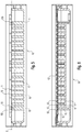
- FIG. 3 shows a further view of the underside of the luminaire housing 110, but the covers 60, 121 and the LED lamps have now been omitted, such that the interior of the heat sink 10 according to the invention can now be seen.
- Figure 3 as well as the others Figures 4 to 6 accordingly show that the heat sink 10 in turn has rib-like structures 15 to 17, which, however, are now not directed towards the outside, but - ideally in one piece - extend from the outer surfaces 11 and 12 into the interior enclosed by these outer surfaces 11, 12.
- the ribs 15 to 17 are designed such that they penetrate the interior and have end edges 18, all of which are in a common plane E - see Figure 5 - lie.
- the end edges 18 of the ribs 15 to 17 thus form an essentially flat support for an LED circuit board and can then be used to transmit the heat that occurs during the operation of the LEDs to the outer surfaces 11, 12 of the heat sink 10.
- the two heat sinks 10 each have a plurality of ribs 15 to 17 aligned in parallel.
- three different types of ribs are provided.
- the first type is used for the first and last rib 15 and is provided with a central extension 15a with a bore 15b. This Both ribs 15 are responsible for fastening the LED board 50 and in particular enable the board 50 to be screwed to the heat sink 10.
- the ribs 16 and 17 of the second and third types are arranged alternately between the two end ribs 15.
- the only difference is that the ribs of the second type 16 have central stiffeners, whereas the ribs of the third type 17 have an unchanged cross section over their entire width.
- This change in the diameter in the central region of the ribs 16 is also shown in the sectional view according to FIG Figure 5 recognizable, here a section along the line II of Figure 3 is shown.
- the use of the three different rib types 15 to 17 described above is not absolutely necessary and the ribs can also be designed in another way. It is essential, however, that they all end in a common plane E, irrespective of the shape of the outer surfaces of the heat sink 10, and accordingly form a planar support option for the LED circuit board.
- the outer contour of the heat sink 10 can therefore be chosen essentially freely and, in particular, can be optimized in order to achieve an efficient air flow, since this can be compensated in a suitable manner by the ribs 15 to 17, such that, in spite of everything, a flat support for the LED -Board 50 is achieved.
- the ribs 15 to 17 do not necessarily have to be aligned parallel to one another, as shown, but can optionally also run diagonally or in the form of a grid.
- FIGS Figures 4 and 6 The arrangement of an LED circuit board 50 on the heat sink 10 designed according to the invention is shown in FIGS Figures 4 and 6 shown where Figure 6 again a section, now along the line II-II of Figure 3 shows. It can be seen here that the circuit board 50 actually rests on the upper or end edges of the ribs 15 to 17. According to the representation according to the Figures 4 and 6 ideally, the arrangement of the ribs is matched to the arrangement of the LEDs 52 on the circuit board 50. In particular, it is ideally provided that the LEDs 52 always rest exactly above the edge of an associated rib 15 to 17, so that the heat generated during operation can be released directly to the rib 15, 16 or 17 running below the LED 52. In this case, a particularly good transfer of heat to the heat sink 10 is ensured.
- the outer walls 11 and 12 of the heat sink 10 together with the LED circuit board 50 enclose an interior of the heat sink 10 through which the fins 15-17 used for mounting the circuit board 50 extend.
- the interior itself thus has numerous cavities, as shown in the sectional view of the Figures 4 to 6 is recognizable.
- an essentially closed system with surfaces that are as smooth as possible is formed on the outside.
- good heat dissipation is achieved in spite of everything, since on the one hand the configuration shown enables good heat transfer to the heat sink, on the other hand the outer surfaces 11 and 12 enable an optimized flow of the ambient air.
- the heat sink 10 in the exemplary embodiment shown is an integral part of the lamp housing 110, which in this case is then preferably designed as a one-piece component.
- the concept according to the invention can, however, also be implemented with separately designed heat sinks.
- the present invention thus provides a heat sink in which the problems described at the outset are avoided in comparison with the classic design of heat sinks, but on the other hand, in spite of everything, an efficient and good dissipation of the heat occurring during operation is made possible.
Landscapes
- Engineering & Computer Science (AREA)
- General Engineering & Computer Science (AREA)
- Microelectronics & Electronic Packaging (AREA)
- Manufacturing & Machinery (AREA)
- Computer Hardware Design (AREA)
- Power Engineering (AREA)
- Arrangement Of Elements, Cooling, Sealing, Or The Like Of Lighting Devices (AREA)
Abstract
Description
- Die vorliegende Erfindung betrifft einen Kühlkörper, der zur Lagerung einer LED-Platine vorgesehen ist und dazu dient, die während des Betriebs der LEDs entstehende Wärme abzuleiten. Ferner betrifft die Erfindung eine Anordnung bestehend aus einem Kühlkörper und einer zugehörigen LED-Platine sowie eine Leuchte mit einer entsprechenden Anordnung.
- Der Einsatz von LEDs zu Beleuchtungszwecken führt zu dem Erfordernis, die während des Betriebs der LEDs auftretende Wärme effizient abzuführen. Auch wenn LEDs im Vergleich zu herkömmlichen Lichtquellen - wie z.B. Glühbirnen - eine verbesserte Effizienz aufweisen, besteht nach wie vor das Problem, dass während des Betriebs eine nicht unwesentliche Menge der zugeführten elektrischen Energie in Verlust-Wärme umgesetzt wird. Dieses Problem ist bei LEDs insbesondere relevant, da diese im Vergleich zu klassischen Lichtquellen sehr geringe Abmessungen aufweisen und dementsprechend konzentriert hohe Temperaturen auftreten können. Eine Beschädigung der LEDs sowie weiterer Komponenten, die für die Stromversorgung der LEDs verantwortlich sind, kann nur vermieden werden, wenn mit Hilfe geeigneter Maßnahmen eine zuverlässige Kühlung ermöglicht wird.
- Überwiegend werden LEDs durch den Einsatz sogenannter Kühlkörper passiv gekühlt. Es handelt sich hierbei um Elemente aus einem gut leitfähigem Material, welche einerseits thermisch mit der LED beziehungsweise einer LED-Platine gekoppelt sind und andererseits derart ausgeführt sind, dass sie die Wärme weiterleiten und insbesondere an einem von den LEDs entfernten Ort an die Umgebung abgeben. Als geeignetes Material zur Realisierung derartiger Kühlkörper hat sich in der Vergangenheit insbesondere Aluminium erwiesen.
- Um eine gute thermische Kopplung zwischen Kühlkörper und LED-Platine zu gewährleisten, sind Kühlkörper üblicherweise derart ausgebildet, dass sie eine plane geschlossene Auflagefläche für die LED-Platine bilden. Allenfalls Bohrungen, mit deren Hilfe ein Verschrauben der Platine mit dem Kühlkörper erfolgen kann, sind in der Auflagefläche vorgesehen, sodass möglichst großflächig ein thermischer Kontakt zwischen der Wärmequelle, also der LED-Platine, und dem Kühlkörper vorliegt. Das Abgeben der Wärme an die Umgebungsluft wird dann in der Regel dadurch gefördert, dass der Kühlkörper eine verhältnismäßig große Oberfläche aufweist, die in Kontakt mit der Umgebung ist. Um trotz allem die Abmessungen des Kühlkörpers in einem vertretbaren Rahmen zu halten, wird dessen Oberfläche üblicherweise dadurch vergrößert, dass diese eine Vielzahl rippenartiger Strukturen, sogenannter Kühlfinnen, aufweist. Zwischen den einzelnen Finnen bzw. Rippen kann dann idealerweise die Umgebungsluft strömen, um einerseits einen guten Wärmeaustausch zu erzielen, andererseits dann sofort abströmen zu können, um wiederum kühlere Luft in Kontakt mit dem Kühlkörper treten zu lassen.
- Das oben beschriebene Konzept eines Kühlkörpers mit einer planen Auflagefläche für die Wärmequelle sowie Kühlrippen zum effizienten Wärmeaustausch mit der Umgebungsluft hat sich vielfach bewährt. Problematisch ist auf der anderen Seite, dass die durch die Kühlrippen vergrößerte Oberfläche dazu neigt, das Anlagern von Schmutz- und Staubpartikeln zu fördern. Insbesondere für den Fall des Einsatzes derartiger Kühlkörper in Industriebereichen, bei denen die Luft relativ staubhaltig sein kann, führt dies dazu, dass die Oberfläche des Kühlkörpers verhältnismäßig schnell mit Staub behaftet ist. Die Kühlrippen fördern dabei nicht nur das Anlagern von Staub, sondern erschweren darüber hinaus auch eine Reinigung des Kühlkörpers, da oftmals zwischen den einzelnen Rippen nur schmale Spalte oder Freiräume verbleiben.
- Der vorliegenden Erfindung liegt deshalb die Aufgabenstellung zu Grunde, eine Möglichkeit zur effizienten Kühlung einer LED-Lichtquelle zur Verfügung zu stellen, bei der die oben genannten Probleme vermieden werden.
- Die Aufgabe wird durch einen Kühlkörper für eine LED-Platine, der die Merkmale des Anspruchs 1 aufweist, gelöst. Vorteilhafte Weiterbildungen der Erfindung sind Gegenstand der abhängigen Ansprüche.
- Die erfindungsgemäße Lösung beruht auf dem Gedanken, einen Kühlkörper für eine LED-Platine derart zu gestalten, dass er möglichst glatte Außenflächen aufweist, welche weniger stark das Anlagern von Schmutz- oder Staubpartikeln fördern und darüber hinaus auch deutlich einfacher zu reinigen sind. Der Wärmeaustausch mit der Umgebung erfolgt bei dem erfindungsgemäßen Kühlkörper also nicht durch eine Vielzahl einzelner Kühlrippen, sondern stattdessen über eine möglichst glatte Außenfläche. Auch der erfindungsgemäße Kühlkörper weist rippenartige Strukturen auf. Diese sind nun allerdings nicht unmittelbar für den Wärmeaustausch mit der Umgebung verantwortlich, sondern dienen in erster Linie der thermischen Kopplung mit der LED-Platine. Sie erstrecken sich einstückig ausgehend von dem Außenmantel des Kühlkörpers derart, dass dem Außenmantel gegenüberliegende Abschlusskanten der Rippen in einer gemeinsamen Ebene verlaufen, so dass sie eine im Wesentlichen plane Auflage für eine LED-Platine bilden.
- Erfindungsgemäß wird also ein Kühlkörper für eine LED-Platine vorgeschlagen, der einen Außenmantel aufweist, der zumindest einen im Wesentlichen geschlossenen Oberflächenbereich aufweist, von dem aus sich einstückig mit dem Außenmantel verbundene Rippen erstrecken, wobei dem geschlossenen Oberflächenbereich gegenüberliegende Abschlusskanten der Rippen derart in einer gemeinsamen Ebene verlaufen, dass sie eine im Wesentlichen plane Auflage für eine LED-Platine bilden.
- Mit der vorliegenden Erfindung wird sozusagen ein klassischer Kühlkörper invertiert. Die üblicherweise im Wesentlichen geschlossene Auflagefläche, die normalerweise der Lagerung und thermischen Kopplung mit der Wärmequelle dient, wird nunmehr zum Wärmeaustausch mit der Umgebung verwendet, während hingegen die Kühlrippen für die Übertragung der Wärme von der LED-Platine zum Außenmantel des Kühlkörpers verantwortlich sind und derart ausgeführt sind, dass sie eine plane Auflage für die LED-Platine bilden. Der geschlossene Oberflächenbereich des Außenmantels muss dabei nicht zwingend plan ausgeführt sein, sondern kann auch anderweitig geformt, beispielsweise gekrümmt sein. Die Gestaltung dieser Außenfläche kann dabei insbesondere dahingehend optimiert sein, dass ein Vorbeiströmen der Luft gefördert wird. Beispielsweise hat sich eine giebelartige Konstruktion mit gekrümmten Außenflächen als vorteilhaft herausgestellt. Somit wird trotz allem eine effiziente Kühlung der LED-Lichtquelle ermöglicht, gleichzeitig jedoch werden die oben geschilderten Probleme klassischer Kühlkörper vermeiden.
- Vorzugsweise sind die Rippen des Kühlkörpers parallel zueinander ausgerichtet. Ferner ist in besonders bevorzugter Weise vorgesehen, dass der Außenmantel des Kühlkörpers vollständig geschlossen ist. Der geschlossene Oberflächenbereich des Kühlkörpers kann dabei wie bereits erwähnt gekrümmt ausgebildet sein, da in diesem Fall ein besonders effizientes Vorbeiströmen der zur Kühlung genutzten Luft realisiert werden kann.
- Eine erfindungsgemäße Anordnung besteht aus einem Kühlkörper in der oben beschriebenen Weise sowie einer LED-Platine, die auf den Abschlusskanten der Rippen des Kühlkörpers angeordnet ist. Hierbei ist vorzugsweise vorgesehen, dass die LED-Platine mehrere LEDs aufweist, wobei sämtliche LEDs jeweils oberhalb der Abschlusskanten der Rippen des Kühlkörpers positioniert sind. Die räumliche Nähe der LEDs zu den Rippen führt dazu, dass in besonders effizienter Weise die Wärme auf den Kühlkörper übertragen und durch die Rippen weitergeleitet werden kann. Vorzugsweise sind hierbei die LEDs im Wesentlichen gleichmäßig verteilt auf der Platine angeordnet. Letztendlich ergibt sich idealerweise eine Konfiguration, bei der der Außenmantel des Kühlkörpers und die LED-Platine gemeinsam einen Kühlkörperinnenraum im Wesentlichen vollständig umschließen, wobei sich durch den Innenraum dann die Rippen erstrecken.
- Schließlich wird erfindungsgemäß eine Leuchte vorgeschlagen, welche eine Anordnung bestehend aus einem Kühlkörper und einer LED-Platine gemäß der vorliegenden Erfindung aufweist.
- Nachfolgend soll die Erfindung an Hand der beiliegenden Zeichnung näher erläutert werden. Es zeigen:
- Figuren 1 und 2
- Ansichten einer Leuchte, bei der zwei Kühlkörper gemäß der vorliegenden Erfindung zum Einsatz kommen;
- Figur 3
- eine weitere Ansicht der Leuchte der
Figuren 1 und 2 , wobei der Innenraum der erfindungsgemäßen Kühlkörper erkennbar ist; - Figur 4
- einer perspektivische Schnittdarstellung der Leuchte der
Figuren 1 und 2 ; - Figur 5
- eine Schnittdarstellung des erfindungsgemäßen Kühlkörpers ohne darauf angeordneter LED-Platine und
- Figur 6
- eine Schnittdarstellung des Kühlkörpers mit einer darauf angeordneten LED-Platine.
- Das in den
Figuren 1 und 2 dargestellte Ausführungsbeispiel einer Leuchte 100 mit erfindungsgemäßen Kühlkörpern geht von einer Leuchte aus, wie sie beispielsweise in derWO 2014/086770 A1 der Anmelderin beschrieben ist. Es handelt sich um eine sogenannte High Bay-Leuchte, also eine Leuchte, die beispielsweise zur Beleuchtung von größeren Hallen oder Industriekomplexen verwendet wird. Da hier die Leuchte 100 üblicherweise in einem verhältnismäßig großen Abstand zum Boden montiert ist, soll Licht mit hoher Intensität erzeugt werden, welches dann auf den darunterliegenden Bereich der Halle gestrahlt wird. Dementsprechend kommen hier leistungsstarke Leuchtmittel zum Einsatz, die in geeigneter Weise gekühlt werden müssen. Allerdings ist das erfindungsgemäße Konzept der speziellen Ausgestaltung des Kühlkörpers nicht auf die dargestellte Leuchte beschränkt, sondern kann vielfach auch bei anderen Leuchtentypen Verwendung finden. - Die in den
Figuren 1 und 2 dargestellte Leuchte 100 weist also ein Gehäuse 110 mit einer im vertikalen Schnitt etwa trapezartigen Konfiguration auf, mit einer zur Unterseite hin erweiterten rechteckigen bzw. quadratischen Öffnung 111. Innerhalb des Gehäuses 110 ist herbei mittig ein Bereich 120 ausgebildet, der zur Lagerung elektronischer Komponenten zur Stromversorgung der Leuchtmittel dient. Insbesondere können in diesem zentralen Bereich 120 beispielsweise ein oder mehrere Betriebsgeräte gelagert werden, welche die der Leuchte 100 zugeführte Versorgungsspannung in eine geeignete Betriebsspannung für die LED-Leuchtmittel umsetzen. Dieser zentrale Bereich, der auch inFigur 4 erkennbar ist, ist im Betrieb durch eine Abdeckplatte 121 zur Unterseite hin verschlossen. - Die Leuchtmittel selbst sind parallel zu beiden Seiten des zentralen Bereichs 120 angeordnet und insbesondere in der Ansicht gemäß
Figur 2 sowie denFiguren 4 und6 erkennbar. Insbesondere kommen zwei LED-Platinen 50 zum Einsatz, welche eine Vielzahl matrixartig angeordneter LEDs 52 aufweisen. Üblicherweise sind die LEDs 52 hier im Wesentlichen gleichmäßig verteilt angeordnet, wobei jedoch gegebenenfalls an bestimmten Positionen einzelne LEDs 52 fehlen können, um beispielsweise ein Verschrauben der Platine 50 mit dem nachfolgend noch näher beschriebenen Kühlkörper zu ermöglichen. - Den LED-Platinen vorgeordnet ist jeweils eine zumindest teilweise lichtdurchlässige Abdeckung 60, welche die zugehörige Platine 50 vollständig überdeckt und somit vor äußeren Einflüssen schützt. Diese Abdeckung 60 kann integriert optische Elemente, beispielsweise Linsen, aufweisen, mit deren Hilfe das von den LEDs emittierte Licht in geeigneter Weise beeinflusst wird. Dabei ist idealerweise jeder LED 52 jeweils eine einzelne Linse zugeordnet.
- Eine besondere Eigenschaft der in der oben genannten internationalen Anmeldung beschriebenen Leuchte, die auch bei der in den
Figuren 1 und 2 dargestellten erfindungsgemäßen Leuchte 100 zum Einsatz kommt, besteht darin, dass die Unterseite des Leuchtengehäuses 110 nicht vollständig durch die Abdeckung 121 des zentralen Bereichs 120 sowie die beiden Abdeckungen 60 für die Leuchtmittel geschlossen ist. Stattdessen sind zu beiden Seiten der LED-Leuchtmittel jeweils Durchgangsöffnungen 125, 126 oder Freiräume vorgesehen, die das Durchströmen von Luft von der Unterseite der Leuchte 100 her zur Oberseite hin ermöglichen. Dieses Konzept, welches in der oben erwähnten Schrift ausführlich erläutert wird, sieht also vor, dass die unterhalb der Leuchte 100 befindliche Luft, welche eine niedrigere Temperatur aufweist, entsprechend den dargestellten Pfeilen in denFiguren 1 und 2 zu beiden Seiten der Leuchtmittel jeweils durch das Leuchtengehäuse 110 strömt und an der Oberseite wieder austritt, wodurch eine effiziente Kühlung der LED-Leuchtmittel erzielt wird. Während des Betriebs der Leuchte 100 wird hierdurch ein Kamineffekt generiert, der dafür sorgt, dass die LED-Leuchtmittel kontinuierlich von Kühlluft umströmt werden, sodass trotz der hohen Leistung der Leuchtmittel und damit der starken Wärmeentwicklung keine Überhitzung der elektronischen Komponenten zu befürchten ist. - Wie der Darstellung der
Figuren 1 und 2 entnehmbar ist, ist die Außenseite des Gehäuses 110 an beiden Längsseiten 115 mit leicht rippenartigen Strukturen 116 versehen. Diese Seitenwände 115 sind allerdings wie bereits erwähnt durch die Durchströmöffnungen 125, 126 für die Luft von den LED-Leuchtmitteln getrennt und tragen dementsprechend nur zu einem geringen Grad zur Kühlung der LED-Leuchtmittel bei. Die eigentliche Kühlung muss durch denjenigen Bereich des Leuchtengehäuses 110 erfolgen, der unmittelbar in thermischem Kontakt mit den LED-Platinen 50 ist. Es handelt sich hierbei jeweils um einen in der nachfolgend beschriebenen erfindungsgemäßen Weise ausgestalteten Kühlkörper. - Bei der Leuchte gemäß dem Stand der Technik war der Kühlkörper derart ausgestaltet, dass er eine plane Auflagefläche für die zugehörige LED-Platine bildete. An der Oberseite hingegen wies dieser Kühlkörper die bereits eingangs geschilderten sich vertikal erstreckenden Kühlrippen auf, welche auf Grund ihrer großen Oberfläche eine geeignete Übertragung der Wärme an die Umgebungsluft ermöglichten.
- Bei der erfindungsgemäßen Leuchte 100 ist nunmehr vorgesehen, dass auf die nach oben bzw. außen gerichteten Rippen verzichtet wird. Stattdessen sind die mit dem Bezugszeichen 10 versehenen Kühlkörper derart ausgeführt, dass sie möglichst glatte und geschlossene Oberflächenbereiche aufweisen. Im dargestellten Ausführungsbeispiel ist insbesondere vorgesehen, dass die Außenfläche eines Kühlkörpers 10 im Wesentlichen durch zwei sich giebelartig zur Oberseite hin erstreckende Wände 11 und 12 gebildet wird, die vorzugsweise keine Öffnungen, insbesondere jedoch keine rippenartigen Erweiterungen zur Vergrößerung ihrer Oberfläche aufweisen. Stattdessen sind die Wände 11, 12 wie bereits erwähnt möglichst glatt ausgeführt, sodass das Anlagern von Staub- oder Schmutzpartikeln vermieden wird. Gleichzeitig können sie allerdings - wie
Figur 1 entnommen werden kann - eine gewisse konkave Krümmung aufweisen. Diese Krümmung sowie die entsprechende Neigung der Oberflächen 11, 12 kann dabei derart gewählt werden, dass die durch die Öffnungen strömende Luft 125, 126 möglichst effizient an den Außenflächen 11, 12 des Kühlkörpers 10 entlang strömt und dementsprechend Wärme effizient abgeführt wird. Im Vergleich zu rippenartigen Erweiterungen kann mit Hilfe der glatten Außenflächen 11, 12 sogar eine deutlich bessere Luftströmung erzielt werden, sodass trotz der im Vergleich zu klassischen Kühlkörpern reduzierten Oberfläche eine vergleichbare Ableitung der Wärme an die Umgebungsluft realisiert werden kann. - Die Ableitung der während des Betriebs durch die LED-Leuchtmittel generierten Wärme ist allerdings nur dann möglich, wenn eine gute thermische Kopplung zwischen dem Kühlkörper 10 und den LED-Leuchtmitteln vorliegt. Idealerweise sollte deshalb der Kühlkörper 10 möglichst massiv gestaltet sein, da dies die größtmögliche Wärmeübertragung gewährleistet. Da eine entsprechend massive Ausgestaltung allerdings auf Grund des damit verbundenen Materialaufwands sowie der Herstellungskosten nicht gerechtfertigt ist, ist bei dem erfindungsgemäßen Kühlkörper 10 eine spezielle Lagerung der LED-Leuchtmittel vorgesehen, die nachfolgend an Hand der weiteren
Figuren 3 bis 6 näher erläutert werden soll. -
Figur 3 zeigt hierzu eine weitere Ansicht der Unterseite des Leuchtengehäuses 110, wobei nunmehr allerdings auf die Darstellung der Abdeckungen 60, 121 sowie der LED-Leuchtmittel verzichtet wurde, derart, dass nunmehr der Innenraum der erfindungsgemäßen Kühlkörper 10 erkennbar ist. -
Figur 3 sowie die weiterenFiguren 4 bis 6 zeigen dementsprechend, dass der Kühlkörper 10 wiederum rippenartige Strukturen 15 bis 17 aufweist, die nunmehr allerdings nicht zur Außenseite hin gerichtet sind, sondern sich - idealerweise einstückig - ausgehend von den Außenflächen 11 und 12 in den von diesen Außenflächen 11, 12 umschlossenen Innenraum erstrecken. Genau genommen sind die Rippen 15 bis 17 derart ausgeführt, dass sie den Innenraum durchsetzen und Abschlusskanten 18 aufweisen, welche alle in einer gemeinsamen Ebene E - sieheFigur 5 - liegen. Damit bilden die Abschlusskanten 18 der Rippen 15 bis 17 eine im Wesentlichen plane Auflage für eine LED-Platine und können dann dazu verwendet werden, die während des Betriebs der LEDs auftretende Wärme an die Außenflächen 11, 12 des Kühlkörpers 10 weiterzuleiten. - Wie die
Figuren 3 bis 6 zeigen, weisen die beiden Kühlkörper 10 jeweils eine Vielzahl von parallel ausgerichteten Rippen 15 bis 17 auf. Im dargestellten Ausführungsbeispiel sind drei verschiedene Arten von Rippen vorgesehen. - Der erste Typ kommt dabei jeweils bei der ersten und letzten Rippe 15 zum Einsatz und ist mit einer zentralen Erweiterung 15a mit einer Bohrung 15b versehen. Diese beiden Rippen 15 sind für die Befestigung der LED-Platine 50 verantwortlich und ermöglichen insbesondere ein Verschrauben der Platine 50 mit dem Kühlkörper 10.
- Zwischen den beiden End-Rippen 15 sind dann beispielsweise alternierend die Rippen 16 und 17 des zweiten und dritten Typs angeordnet. Diese unterscheiden sich lediglich darin, dass bei den Rippen des zweiten Typs 16 zentrale Versteifungen vorgesehen sind, während hingegen die Rippen des dritten Typs 17 über ihre gesamte Breite hinweg einen unveränderten Querschnitt aufweisen. Diese Veränderung des Durchmessers im zentralen Bereich der Rippen 16 ist auch in der Schnittdarstellung gemäß
Figur 5 erkennbar, wobei hier ein Schnitt entlang der Gerade I-I vonFigur 3 gezeigt ist. - Anzumerken ist, dass die Nutzung der oben beschriebenen drei unterschiedlichen Rippen-Typen 15 bis 17 nicht zwingend erforderlich ist und die Rippen auch anderweitig gestaltet sein können. Wesentlich ist allerdings, dass sie alle unabhängig von der Form der Außenflächen des Kühlkörpers 10 in einer gemeinsamen Ebene E enden und dementsprechend eine plane Auflagemöglichkeit für die LED-Platine bilden. Die Außenkontur des Kühlkörpers 10 kann also im Wesentlichen frei gewählt werden und insbesondere optimiert werden, um eine effiziente Luftströmung zu erzielen, da dies durch die Rippen 15 bis 17 in geeigneter Weise ausgeglichen werden kann, derart, dass trotz allem eine plane Auflage für die LED-Platine 50 erzielt wird. Die Rippen 15 bis 17 müssen dabei auch nicht wie dargestellt zwangsläufig parallel zueinander ausgerichtet sein, sondern können auch gegebenenfalls diagonal oder in Form eines Rasters verlaufen.
- Die Anordnung einer LED-Platine 50 auf dem erfindungsgemäß ausgebildeten Kühlkörper 10 ist in den
Figuren 4 und6 gezeigt, wobeiFigur 6 wiederum einen Schnitt, nunmehr entlang der Geraden II-II vonFigur 3 zeigt. Erkennbar ist hierbei, dass die Platine 50 tatsächlich auf den Ober- beziehungsweise Abschlusskanten der Rippen 15 bis 17 aufliegt. Dabei ist entsprechend der Darstellung gemäß denFiguren 4 und6 idealerweise vorgesehen, dass die Anordnung der Rippen auf die Anordnung der LEDs 52 auf der Platine 50 abgestimmt ist. Insbesondere ist idealerweise vorgesehen, dass die LEDs 52 immer genau oberhalb der Kante einer zugehörigen Rippe 15 bis 17 ruhen, sodass die während des Betriebs entstehende Wärme unmittelbar an die unterhalb der LED 52 verlaufende Rippe 15, 16 oder 17 abgegeben werden kann. In diesem Fall ist eine besonders gute Übertragung der Wärme auf den Kühlkörper 10 gewährleistet. - Letztendlich umschließen also idealerweise die Außenwände 11 und 12 des Kühlkörpers 10 gemeinsam mit der LED-Platine 50 einen Innenraum des Kühlkörpers 10, durch den sich die zur Lagerung der Platine 50 genutzten Rippen 15-17 erstrecken. Der Innenraum selbst weist also zahlreiche Hohlräume auf, wie dies in der Schnittdarstellung der
Figuren 4 bis 6 erkennbar ist. Zur Außenseite hin wird hingegen ein im Wesentlichen geschlossenes System mit möglichst glatten Oberflächen gebildet. Wie bereits erwähnt, wird trotz allem eine gute Ableitung der Wärme erzielt, da einerseits die dargestellte Konfiguration eine gute Übertragung der Wärme auf den Kühlkörper ermöglicht, andererseits die Außenflächen 11 und 12 eine optimierte Strömung der Umgebungsluft ermöglichen. - Anzumerken ist hierbei, dass der Kühlkörper 10 im dargestellten Ausführungsbeispiel integraler Bestandteil des Leuchtengehäuses 110 ist, welches in diesem Fall dann vorzugsweise als einstückiges Bauteil ausgeführt ist. Selbstverständlich kann das erfindungsgemäße Konzept allerdings auch bei separat ausgebildeten Kühlkörpern realisiert werden.
- Insgesamt wird durch die vorliegende Erfindung also ein Kühlkörper zur Verfügung gestellt, bei dem die eingangs geschilderten Probleme im Vergleich zur klassischer Ausgestaltung von Kühlkörpern vermieden werden, andererseits jedoch trotz allem eine effiziente und gute Ableitung der während des Betriebs auftretenden Wärme ermöglicht wird.
Claims (14)
- Kühlkörper (10) für eine LED-Platine (50),
aufweisend einen Außenmantel, der zumindest einen geschlossenen Oberflächenbereich (11, 12) aufweist, von dem sich aus einstückig mit dem Außenmantel verbundene Rippen (15, 16, 17) erstrecken,
wobei dem geschlossenen Oberflächenbereich (11, 12) gegenüberliegende Abschlusskanten (18) der Rippen (15, 16, 17) derart in einer gemeinsamen Ebene (E) verlaufen, dass sie eine im Wesentlichen plane Auflage für eine LED-Platine (50) bilden. - Kühlkörper nach Anspruch 1,
dadurch gekennzeichnet,
dass die Rippen (15, 16, 17) parallel zueinander ausgerichtet sind. - Kühlkörper nach Anspruch 1 oder 2,
dadurch gekennzeichnet,
dass zumindest einige der Rippen (15, 16, 17) Bohrungen (15b) aufweisen, über die ein Verschrauben mit der LED-Platine (50) ermöglicht wird. - Kühlkörper nach einem der vorherigen Ansprüche,
dadurch gekennzeichnet,
dass der Außenmantel des Kühlkörpers (10) vollständig geschlossen ist. - Kühlkörper gemäß einem der vorherigen Ansprüche,
dadurch gekennzeichnet,
dass der geschlossene Oberflächenbereich (11, 12) gekrümmt ausgebildet ist. - Kühlkörper nach einem der vorherigen Ansprüche,
dadurch gekennzeichnet,
dass der Außenmantel des Kühlkörpers (10) durch zwei giebelartig aufeinander zu laufende Außenflächen gebildet ist, welche vorzugsweise eine Krümmung aufweisen. - Anordnung bestehend aus einem Kühlkörper (10) gemäß einem der vorherigen Ansprüche sowie einer LED-Platine (50), die auf den Abschlusskanten (18) der Rippen (15, 16, 17) des Kühlkörpers (10) angeordnet ist.
- Anordnung nach Anspruch 7,
dadurch gekennzeichnet,
dass die LED-Platine (50) mehrere LEDs (52) aufweist, wobei sämtliche LEDs (52) jeweils oberhalb der Abschlusskante (18) einer Rippe (15, 16, 17) des Kühlkörpers (10) positioniert sind. - Anordnung nach Anspruch 7 oder 8,
dadurch gekennzeichnet,
dass die LEDs (52) im Wesentlichen gleichmäßig verteilt auf der LED-Platine (50) angeordnet sind. - Anordnung nach einem der Ansprüche 7 bis 9,
dadurch gekennzeichnet,
dass der Außenmantel des Kühlkörpers (10) und die LED-Platine (50) gemeinsam einen Kühlkörperinnenraum umschließen, durch den sich die Rippen (15, 16, 17) erstrecken. - Leuchte (100), aufweisend zumindest eine Anordnung bestehend aus einem Kühlkörper (10) und einer LED-Platine (50) gemäß einem der Ansprüche 5 bis 8.
- Leuchte nach Anspruch 11,
dadurch gekennzeichnet,
dass die Leuchte (100) an zumindest einer Seite der Anordnung bestehend aus dem Kühlkörper (10) und der LED-Platine (50) Luftdurchströmöffnungen (125, 126) aufweist. - Leuchte nach Anspruch 12,
dadurch gekennzeichnet,
dass zu beiden Seiten der Anordnung bestehend aus dem Kühlkörper (10) und der LED-Platine (50) Luftdurchströmöffnungen (125, 126) ausgebildet sind. - Leuchte nach einem der Ansprüche 11 bis 13,
dadurch gekennzeichnet,
dass der Kühlkörper (10) einstückiger Bestandteil eines Gehäuseteils ist.
Applications Claiming Priority (1)
| Application Number | Priority Date | Filing Date | Title |
|---|---|---|---|
| DE202019100381.2U DE202019100381U1 (de) | 2019-01-24 | 2019-01-24 | Kühlkörper für eine LED-Platine |
Publications (2)
| Publication Number | Publication Date |
|---|---|
| EP3686481A1 true EP3686481A1 (de) | 2020-07-29 |
| EP3686481B1 EP3686481B1 (de) | 2020-12-16 |
Family
ID=69190653
Family Applications (1)
| Application Number | Title | Priority Date | Filing Date |
|---|---|---|---|
| EP20153324.7A Active EP3686481B1 (de) | 2019-01-24 | 2020-01-23 | Kühlkörper für eine led-platine |
Country Status (3)
| Country | Link |
|---|---|
| EP (1) | EP3686481B1 (de) |
| AT (1) | AT16948U1 (de) |
| DE (1) | DE202019100381U1 (de) |
Citations (4)
| Publication number | Priority date | Publication date | Assignee | Title |
|---|---|---|---|---|
| US20130027935A1 (en) * | 2011-07-29 | 2013-01-31 | Christopher Ladewig | Modular Lighting System |
| US20130214665A1 (en) * | 2012-02-22 | 2013-08-22 | Toshiba Lighting & Technology Corporation | Lamp Apparatus and Luminaire |
| WO2014086770A1 (de) | 2012-12-04 | 2014-06-12 | Zumtobel Lighting Gmbh | Leuchte mit luftleitflächen |
| US20180054978A1 (en) * | 2016-08-30 | 2018-03-01 | GE Lighting Solutions, LLC | Luminaire including a heat dissipation structure |
Family Cites Families (5)
| Publication number | Priority date | Publication date | Assignee | Title |
|---|---|---|---|---|
| TWI333533B (en) * | 2007-07-06 | 2010-11-21 | Harvatek Corp | Led lamp structure and system with high-efficiency heat-dissipating function |
| KR101027908B1 (ko) * | 2010-08-26 | 2011-04-12 | 주식회사 에이팩 | 히트싱크와 히트싱크를 포함하는 발광다이오드 조명기구 및 그 제조방법 |
| DE102011081369A1 (de) * | 2011-08-23 | 2013-02-28 | Trilux Gmbh & Co. Kg | Leuchte, insbesondere LED-Leuchte mit passiver Kühlung |
| KR101121947B1 (ko) * | 2011-08-31 | 2012-03-09 | 오성덕 | 바형 투광등 |
| US20130083522A1 (en) * | 2011-10-03 | 2013-04-04 | Mark Turner Bowers | Light Fixture Using Light Emitting Diodes |
-
2019
- 2019-01-24 DE DE202019100381.2U patent/DE202019100381U1/de active Active
- 2019-03-27 AT ATGM50048/2019U patent/AT16948U1/de unknown
-
2020
- 2020-01-23 EP EP20153324.7A patent/EP3686481B1/de active Active
Patent Citations (4)
| Publication number | Priority date | Publication date | Assignee | Title |
|---|---|---|---|---|
| US20130027935A1 (en) * | 2011-07-29 | 2013-01-31 | Christopher Ladewig | Modular Lighting System |
| US20130214665A1 (en) * | 2012-02-22 | 2013-08-22 | Toshiba Lighting & Technology Corporation | Lamp Apparatus and Luminaire |
| WO2014086770A1 (de) | 2012-12-04 | 2014-06-12 | Zumtobel Lighting Gmbh | Leuchte mit luftleitflächen |
| US20180054978A1 (en) * | 2016-08-30 | 2018-03-01 | GE Lighting Solutions, LLC | Luminaire including a heat dissipation structure |
Also Published As
| Publication number | Publication date |
|---|---|
| AT16948U1 (de) | 2020-12-15 |
| DE202019100381U1 (de) | 2020-04-27 |
| EP3686481B1 (de) | 2020-12-16 |
Similar Documents
| Publication | Publication Date | Title |
|---|---|---|
| EP2929237B1 (de) | Leuchte mit luftleitflächen | |
| EP2556296B1 (de) | Leuchtengehäuse | |
| EP2487411B1 (de) | Kühlkörper für LED-Leuchte | |
| EP3056805B1 (de) | Langgestreckte optik für led-module | |
| DE10326083B4 (de) | Rippenkonstruktion zur Wärmeabführung und Baugruppe mit einer solchen | |
| EP2439445B1 (de) | LED-Leuchte mit gebogenem Lichtabgabebereich | |
| EP3686481B1 (de) | Kühlkörper für eine led-platine | |
| EP2748515B1 (de) | Lichtquellenvorrichtung | |
| EP2854489B1 (de) | LED-Leuchte | |
| DE202010004317U1 (de) | LED-Leuchte und Kühlkörper | |
| EP2226550B1 (de) | LED-Leuchte mit Kühlkanal | |
| EP2986899B1 (de) | Led-modul sowie anordnung zur lichtabgabe | |
| EP2581657B1 (de) | Kühlkörper-Anordnung für eine LED-Leuchte sowie LED-Leuchte | |
| DE102005054031B4 (de) | Hochleistungsleuchte mit Kühlmantel | |
| EP2622269B1 (de) | Led-leuchte mit auswechselbarer lichtquelle | |
| DE102008006536B4 (de) | Kühlsystem für auf einer Trägerplatine angeordnete Leistungshalbleiter | |
| EP2622258B1 (de) | Kühlkörper und leuchtmodulanordnung für eine leuchte | |
| EP3088796B1 (de) | Profilschiene zur positionierung von led modulen in flächenleuchten | |
| WO2013030333A2 (de) | Kühlkörper für ein downlight, sowie downlight | |
| DE19830909A1 (de) | Bestrahlungselement mit einem Reflektor | |
| EP3418631A1 (de) | Kühlkörper für ein led leuchtmittel und verfahren zum herstellen des kühlkörpers | |
| DE102011018700A1 (de) | Leuchte | |
| DE102009042707A1 (de) | Leuchte | |
| DE202012100813U1 (de) | Kühlanordnung einer Lampenvorrichtung | |
| DE202013100031U1 (de) | LED-Lampe mit Lamellen und längs- sowie querverlaufenden Lüftungskanälen |
Legal Events
| Date | Code | Title | Description |
|---|---|---|---|
| PUAI | Public reference made under article 153(3) epc to a published international application that has entered the european phase |
Free format text: ORIGINAL CODE: 0009012 |
|
| STAA | Information on the status of an ep patent application or granted ep patent |
Free format text: STATUS: REQUEST FOR EXAMINATION WAS MADE |
|
| 17P | Request for examination filed |
Effective date: 20200506 |
|
| AK | Designated contracting states |
Kind code of ref document: A1 Designated state(s): AL AT BE BG CH CY CZ DE DK EE ES FI FR GB GR HR HU IE IS IT LI LT LU LV MC MK MT NL NO PL PT RO RS SE SI SK SM TR |
|
| AX | Request for extension of the european patent |
Extension state: BA ME |
|
| GRAP | Despatch of communication of intention to grant a patent |
Free format text: ORIGINAL CODE: EPIDOSNIGR1 |
|
| STAA | Information on the status of an ep patent application or granted ep patent |
Free format text: STATUS: GRANT OF PATENT IS INTENDED |
|
| RIC1 | Information provided on ipc code assigned before grant |
Ipc: F21W 131/407 20060101ALN20200727BHEP Ipc: F21V 29/76 20150101ALN20200727BHEP Ipc: F21V 29/83 20150101ALI20200727BHEP Ipc: F21Y 105/10 20160101ALN20200727BHEP Ipc: F21W 131/40 20060101ALN20200727BHEP Ipc: F21Y 115/10 20160101ALN20200727BHEP Ipc: F21S 8/06 20060101AFI20200727BHEP |
|
| INTG | Intention to grant announced |
Effective date: 20200902 |
|
| GRAS | Grant fee paid |
Free format text: ORIGINAL CODE: EPIDOSNIGR3 |
|
| GRAA | (expected) grant |
Free format text: ORIGINAL CODE: 0009210 |
|
| STAA | Information on the status of an ep patent application or granted ep patent |
Free format text: STATUS: THE PATENT HAS BEEN GRANTED |
|
| AK | Designated contracting states |
Kind code of ref document: B1 Designated state(s): AL AT BE BG CH CY CZ DE DK EE ES FI FR GB GR HR HU IE IS IT LI LT LU LV MC MK MT NL NO PL PT RO RS SE SI SK SM TR |
|
| REG | Reference to a national code |
Ref country code: GB Ref legal event code: FG4D Free format text: NOT ENGLISH |
|
| REG | Reference to a national code |
Ref country code: DE Ref legal event code: R096 Ref document number: 502020000001 Country of ref document: DE |
|
| REG | Reference to a national code |
Ref country code: IE Ref legal event code: FG4D Free format text: LANGUAGE OF EP DOCUMENT: GERMAN |
|
| REG | Reference to a national code |
Ref country code: AT Ref legal event code: REF Ref document number: 1345925 Country of ref document: AT Kind code of ref document: T Effective date: 20210115 |
|
| PG25 | Lapsed in a contracting state [announced via postgrant information from national office to epo] |
Ref country code: GR Free format text: LAPSE BECAUSE OF FAILURE TO SUBMIT A TRANSLATION OF THE DESCRIPTION OR TO PAY THE FEE WITHIN THE PRESCRIBED TIME-LIMIT Effective date: 20210317 Ref country code: NO Free format text: LAPSE BECAUSE OF FAILURE TO SUBMIT A TRANSLATION OF THE DESCRIPTION OR TO PAY THE FEE WITHIN THE PRESCRIBED TIME-LIMIT Effective date: 20210316 Ref country code: RS Free format text: LAPSE BECAUSE OF FAILURE TO SUBMIT A TRANSLATION OF THE DESCRIPTION OR TO PAY THE FEE WITHIN THE PRESCRIBED TIME-LIMIT Effective date: 20201216 Ref country code: FI Free format text: LAPSE BECAUSE OF FAILURE TO SUBMIT A TRANSLATION OF THE DESCRIPTION OR TO PAY THE FEE WITHIN THE PRESCRIBED TIME-LIMIT Effective date: 20201216 |
|
| REG | Reference to a national code |
Ref country code: NL Ref legal event code: MP Effective date: 20201216 |
|
| PG25 | Lapsed in a contracting state [announced via postgrant information from national office to epo] |
Ref country code: BG Free format text: LAPSE BECAUSE OF FAILURE TO SUBMIT A TRANSLATION OF THE DESCRIPTION OR TO PAY THE FEE WITHIN THE PRESCRIBED TIME-LIMIT Effective date: 20210316 Ref country code: LV Free format text: LAPSE BECAUSE OF FAILURE TO SUBMIT A TRANSLATION OF THE DESCRIPTION OR TO PAY THE FEE WITHIN THE PRESCRIBED TIME-LIMIT Effective date: 20201216 Ref country code: SE Free format text: LAPSE BECAUSE OF FAILURE TO SUBMIT A TRANSLATION OF THE DESCRIPTION OR TO PAY THE FEE WITHIN THE PRESCRIBED TIME-LIMIT Effective date: 20201216 |
|
| PG25 | Lapsed in a contracting state [announced via postgrant information from national office to epo] |
Ref country code: NL Free format text: LAPSE BECAUSE OF FAILURE TO SUBMIT A TRANSLATION OF THE DESCRIPTION OR TO PAY THE FEE WITHIN THE PRESCRIBED TIME-LIMIT Effective date: 20201216 Ref country code: HR Free format text: LAPSE BECAUSE OF FAILURE TO SUBMIT A TRANSLATION OF THE DESCRIPTION OR TO PAY THE FEE WITHIN THE PRESCRIBED TIME-LIMIT Effective date: 20201216 |
|
| REG | Reference to a national code |
Ref country code: LT Ref legal event code: MG9D |
|
| PG25 | Lapsed in a contracting state [announced via postgrant information from national office to epo] |
Ref country code: RO Free format text: LAPSE BECAUSE OF FAILURE TO SUBMIT A TRANSLATION OF THE DESCRIPTION OR TO PAY THE FEE WITHIN THE PRESCRIBED TIME-LIMIT Effective date: 20201216 Ref country code: PT Free format text: LAPSE BECAUSE OF FAILURE TO SUBMIT A TRANSLATION OF THE DESCRIPTION OR TO PAY THE FEE WITHIN THE PRESCRIBED TIME-LIMIT Effective date: 20210416 Ref country code: LT Free format text: LAPSE BECAUSE OF FAILURE TO SUBMIT A TRANSLATION OF THE DESCRIPTION OR TO PAY THE FEE WITHIN THE PRESCRIBED TIME-LIMIT Effective date: 20201216 Ref country code: EE Free format text: LAPSE BECAUSE OF FAILURE TO SUBMIT A TRANSLATION OF THE DESCRIPTION OR TO PAY THE FEE WITHIN THE PRESCRIBED TIME-LIMIT Effective date: 20201216 Ref country code: SK Free format text: LAPSE BECAUSE OF FAILURE TO SUBMIT A TRANSLATION OF THE DESCRIPTION OR TO PAY THE FEE WITHIN THE PRESCRIBED TIME-LIMIT Effective date: 20201216 Ref country code: SM Free format text: LAPSE BECAUSE OF FAILURE TO SUBMIT A TRANSLATION OF THE DESCRIPTION OR TO PAY THE FEE WITHIN THE PRESCRIBED TIME-LIMIT Effective date: 20201216 Ref country code: CZ Free format text: LAPSE BECAUSE OF FAILURE TO SUBMIT A TRANSLATION OF THE DESCRIPTION OR TO PAY THE FEE WITHIN THE PRESCRIBED TIME-LIMIT Effective date: 20201216 |
|
| PG25 | Lapsed in a contracting state [announced via postgrant information from national office to epo] |
Ref country code: PL Free format text: LAPSE BECAUSE OF FAILURE TO SUBMIT A TRANSLATION OF THE DESCRIPTION OR TO PAY THE FEE WITHIN THE PRESCRIBED TIME-LIMIT Effective date: 20201216 |
|
| REG | Reference to a national code |
Ref country code: DE Ref legal event code: R097 Ref document number: 502020000001 Country of ref document: DE |
|
| PG25 | Lapsed in a contracting state [announced via postgrant information from national office to epo] |
Ref country code: IS Free format text: LAPSE BECAUSE OF FAILURE TO SUBMIT A TRANSLATION OF THE DESCRIPTION OR TO PAY THE FEE WITHIN THE PRESCRIBED TIME-LIMIT Effective date: 20210416 Ref country code: MC Free format text: LAPSE BECAUSE OF FAILURE TO SUBMIT A TRANSLATION OF THE DESCRIPTION OR TO PAY THE FEE WITHIN THE PRESCRIBED TIME-LIMIT Effective date: 20201216 |
|
| PLBE | No opposition filed within time limit |
Free format text: ORIGINAL CODE: 0009261 |
|
| STAA | Information on the status of an ep patent application or granted ep patent |
Free format text: STATUS: NO OPPOSITION FILED WITHIN TIME LIMIT |
|
| PG25 | Lapsed in a contracting state [announced via postgrant information from national office to epo] |
Ref country code: AL Free format text: LAPSE BECAUSE OF FAILURE TO SUBMIT A TRANSLATION OF THE DESCRIPTION OR TO PAY THE FEE WITHIN THE PRESCRIBED TIME-LIMIT Effective date: 20201216 Ref country code: IT Free format text: LAPSE BECAUSE OF FAILURE TO SUBMIT A TRANSLATION OF THE DESCRIPTION OR TO PAY THE FEE WITHIN THE PRESCRIBED TIME-LIMIT Effective date: 20201216 |
|
| 26N | No opposition filed |
Effective date: 20210917 |
|
| PG25 | Lapsed in a contracting state [announced via postgrant information from national office to epo] |
Ref country code: DK Free format text: LAPSE BECAUSE OF FAILURE TO SUBMIT A TRANSLATION OF THE DESCRIPTION OR TO PAY THE FEE WITHIN THE PRESCRIBED TIME-LIMIT Effective date: 20201216 |
|
| PG25 | Lapsed in a contracting state [announced via postgrant information from national office to epo] |
Ref country code: ES Free format text: LAPSE BECAUSE OF FAILURE TO SUBMIT A TRANSLATION OF THE DESCRIPTION OR TO PAY THE FEE WITHIN THE PRESCRIBED TIME-LIMIT Effective date: 20201216 |
|
| PG25 | Lapsed in a contracting state [announced via postgrant information from national office to epo] |
Ref country code: IS Free format text: LAPSE BECAUSE OF FAILURE TO SUBMIT A TRANSLATION OF THE DESCRIPTION OR TO PAY THE FEE WITHIN THE PRESCRIBED TIME-LIMIT Effective date: 20210416 |
|
| REG | Reference to a national code |
Ref country code: BE Ref legal event code: MM Effective date: 20220131 |
|
| PG25 | Lapsed in a contracting state [announced via postgrant information from national office to epo] |
Ref country code: LU Free format text: LAPSE BECAUSE OF NON-PAYMENT OF DUE FEES Effective date: 20220123 |
|
| PG25 | Lapsed in a contracting state [announced via postgrant information from national office to epo] |
Ref country code: BE Free format text: LAPSE BECAUSE OF NON-PAYMENT OF DUE FEES Effective date: 20220131 |
|
| PG25 | Lapsed in a contracting state [announced via postgrant information from national office to epo] |
Ref country code: IE Free format text: LAPSE BECAUSE OF NON-PAYMENT OF DUE FEES Effective date: 20220123 |
|
| PGFP | Annual fee paid to national office [announced via postgrant information from national office to epo] |
Ref country code: FR Payment date: 20230124 Year of fee payment: 4 |
|
| P01 | Opt-out of the competence of the unified patent court (upc) registered |
Effective date: 20230530 |
|
| REG | Reference to a national code |
Ref country code: CH Ref legal event code: PL |
|
| PG25 | Lapsed in a contracting state [announced via postgrant information from national office to epo] |
Ref country code: HU Free format text: LAPSE BECAUSE OF FAILURE TO SUBMIT A TRANSLATION OF THE DESCRIPTION OR TO PAY THE FEE WITHIN THE PRESCRIBED TIME-LIMIT; INVALID AB INITIO Effective date: 20200123 |
|
| PG25 | Lapsed in a contracting state [announced via postgrant information from national office to epo] |
Ref country code: LI Free format text: LAPSE BECAUSE OF NON-PAYMENT OF DUE FEES Effective date: 20230131 Ref country code: CH Free format text: LAPSE BECAUSE OF NON-PAYMENT OF DUE FEES Effective date: 20230131 |
|
| PG25 | Lapsed in a contracting state [announced via postgrant information from national office to epo] |
Ref country code: MK Free format text: LAPSE BECAUSE OF FAILURE TO SUBMIT A TRANSLATION OF THE DESCRIPTION OR TO PAY THE FEE WITHIN THE PRESCRIBED TIME-LIMIT Effective date: 20201216 Ref country code: CY Free format text: LAPSE BECAUSE OF FAILURE TO SUBMIT A TRANSLATION OF THE DESCRIPTION OR TO PAY THE FEE WITHIN THE PRESCRIBED TIME-LIMIT Effective date: 20201216 |
|
| PGFP | Annual fee paid to national office [announced via postgrant information from national office to epo] |
Ref country code: DE Payment date: 20240129 Year of fee payment: 5 Ref country code: GB Payment date: 20240123 Year of fee payment: 5 |