EP2854489B1 - LED-Leuchte - Google Patents
LED-Leuchte Download PDFInfo
- Publication number
- EP2854489B1 EP2854489B1 EP14183847.4A EP14183847A EP2854489B1 EP 2854489 B1 EP2854489 B1 EP 2854489B1 EP 14183847 A EP14183847 A EP 14183847A EP 2854489 B1 EP2854489 B1 EP 2854489B1
- Authority
- EP
- European Patent Office
- Prior art keywords
- printed circuit
- led luminaire
- luminaire according
- circuit board
- leds
- Prior art date
- Legal status (The legal status is an assumption and is not a legal conclusion. Google has not performed a legal analysis and makes no representation as to the accuracy of the status listed.)
- Not-in-force
Links
Images

Classifications
-
- H—ELECTRICITY
- H05—ELECTRIC TECHNIQUES NOT OTHERWISE PROVIDED FOR
- H05K—PRINTED CIRCUITS; CASINGS OR CONSTRUCTIONAL DETAILS OF ELECTRIC APPARATUS; MANUFACTURE OF ASSEMBLAGES OF ELECTRICAL COMPONENTS
- H05K3/00—Apparatus or processes for manufacturing printed circuits
- H05K3/0058—Laminating printed circuit boards onto other substrates, e.g. metallic substrates
- H05K3/0061—Laminating printed circuit boards onto other substrates, e.g. metallic substrates onto a metallic substrate, e.g. a heat sink
-
- F—MECHANICAL ENGINEERING; LIGHTING; HEATING; WEAPONS; BLASTING
- F21—LIGHTING
- F21S—NON-PORTABLE LIGHTING DEVICES; SYSTEMS THEREOF; VEHICLE LIGHTING DEVICES SPECIALLY ADAPTED FOR VEHICLE EXTERIORS
- F21S4/00—Lighting devices or systems using a string or strip of light sources
- F21S4/20—Lighting devices or systems using a string or strip of light sources with light sources held by or within elongate supports
- F21S4/28—Lighting devices or systems using a string or strip of light sources with light sources held by or within elongate supports rigid, e.g. LED bars
-
- F—MECHANICAL ENGINEERING; LIGHTING; HEATING; WEAPONS; BLASTING
- F21—LIGHTING
- F21V—FUNCTIONAL FEATURES OR DETAILS OF LIGHTING DEVICES OR SYSTEMS THEREOF; STRUCTURAL COMBINATIONS OF LIGHTING DEVICES WITH OTHER ARTICLES, NOT OTHERWISE PROVIDED FOR
- F21V19/00—Fastening of light sources or lamp holders
- F21V19/001—Fastening of light sources or lamp holders the light sources being semiconductors devices, e.g. LEDs
- F21V19/0015—Fastening arrangements intended to retain light sources
- F21V19/0025—Fastening arrangements intended to retain light sources the fastening means engaging the conductors of the light source, i.e. providing simultaneous fastening of the light sources and their electric connections
-
- F—MECHANICAL ENGINEERING; LIGHTING; HEATING; WEAPONS; BLASTING
- F21—LIGHTING
- F21V—FUNCTIONAL FEATURES OR DETAILS OF LIGHTING DEVICES OR SYSTEMS THEREOF; STRUCTURAL COMBINATIONS OF LIGHTING DEVICES WITH OTHER ARTICLES, NOT OTHERWISE PROVIDED FOR
- F21V19/00—Fastening of light sources or lamp holders
- F21V19/001—Fastening of light sources or lamp holders the light sources being semiconductors devices, e.g. LEDs
- F21V19/003—Fastening of light source holders, e.g. of circuit boards or substrates holding light sources
- F21V19/004—Fastening of light source holders, e.g. of circuit boards or substrates holding light sources by deformation of parts or snap action mountings, e.g. using clips
-
- F—MECHANICAL ENGINEERING; LIGHTING; HEATING; WEAPONS; BLASTING
- F21—LIGHTING
- F21V—FUNCTIONAL FEATURES OR DETAILS OF LIGHTING DEVICES OR SYSTEMS THEREOF; STRUCTURAL COMBINATIONS OF LIGHTING DEVICES WITH OTHER ARTICLES, NOT OTHERWISE PROVIDED FOR
- F21V7/00—Reflectors for light sources
- F21V7/0083—Array of reflectors for a cluster of light sources, e.g. arrangement of multiple light sources in one plane
-
- H—ELECTRICITY
- H05—ELECTRIC TECHNIQUES NOT OTHERWISE PROVIDED FOR
- H05K—PRINTED CIRCUITS; CASINGS OR CONSTRUCTIONAL DETAILS OF ELECTRIC APPARATUS; MANUFACTURE OF ASSEMBLAGES OF ELECTRICAL COMPONENTS
- H05K1/00—Printed circuits
- H05K1/02—Details
- H05K1/14—Structural association of two or more printed circuits
- H05K1/142—Arrangements of planar printed circuit boards in the same plane, e.g. auxiliary printed circuit insert mounted in a main printed circuit
-
- F—MECHANICAL ENGINEERING; LIGHTING; HEATING; WEAPONS; BLASTING
- F21—LIGHTING
- F21V—FUNCTIONAL FEATURES OR DETAILS OF LIGHTING DEVICES OR SYSTEMS THEREOF; STRUCTURAL COMBINATIONS OF LIGHTING DEVICES WITH OTHER ARTICLES, NOT OTHERWISE PROVIDED FOR
- F21V29/00—Protecting lighting devices from thermal damage; Cooling or heating arrangements specially adapted for lighting devices or systems
- F21V29/50—Cooling arrangements
- F21V29/70—Cooling arrangements characterised by passive heat-dissipating elements, e.g. heat-sinks
-
- F—MECHANICAL ENGINEERING; LIGHTING; HEATING; WEAPONS; BLASTING
- F21—LIGHTING
- F21V—FUNCTIONAL FEATURES OR DETAILS OF LIGHTING DEVICES OR SYSTEMS THEREOF; STRUCTURAL COMBINATIONS OF LIGHTING DEVICES WITH OTHER ARTICLES, NOT OTHERWISE PROVIDED FOR
- F21V7/00—Reflectors for light sources
- F21V7/005—Reflectors for light sources with an elongated shape to cooperate with linear light sources
-
- F—MECHANICAL ENGINEERING; LIGHTING; HEATING; WEAPONS; BLASTING
- F21—LIGHTING
- F21Y—INDEXING SCHEME ASSOCIATED WITH SUBCLASSES F21K, F21L, F21S and F21V, RELATING TO THE FORM OR THE KIND OF THE LIGHT SOURCES OR OF THE COLOUR OF THE LIGHT EMITTED
- F21Y2103/00—Elongate light sources, e.g. fluorescent tubes
- F21Y2103/10—Elongate light sources, e.g. fluorescent tubes comprising a linear array of point-like light-generating elements
-
- F—MECHANICAL ENGINEERING; LIGHTING; HEATING; WEAPONS; BLASTING
- F21—LIGHTING
- F21Y—INDEXING SCHEME ASSOCIATED WITH SUBCLASSES F21K, F21L, F21S and F21V, RELATING TO THE FORM OR THE KIND OF THE LIGHT SOURCES OR OF THE COLOUR OF THE LIGHT EMITTED
- F21Y2115/00—Light-generating elements of semiconductor light sources
- F21Y2115/10—Light-emitting diodes [LED]
-
- H—ELECTRICITY
- H05—ELECTRIC TECHNIQUES NOT OTHERWISE PROVIDED FOR
- H05K—PRINTED CIRCUITS; CASINGS OR CONSTRUCTIONAL DETAILS OF ELECTRIC APPARATUS; MANUFACTURE OF ASSEMBLAGES OF ELECTRICAL COMPONENTS
- H05K2201/00—Indexing scheme relating to printed circuits covered by H05K1/00
- H05K2201/10—Details of components or other objects attached to or integrated in a printed circuit board
- H05K2201/10007—Types of components
- H05K2201/10106—Light emitting diode [LED]
-
- H—ELECTRICITY
- H05—ELECTRIC TECHNIQUES NOT OTHERWISE PROVIDED FOR
- H05K—PRINTED CIRCUITS; CASINGS OR CONSTRUCTIONAL DETAILS OF ELECTRIC APPARATUS; MANUFACTURE OF ASSEMBLAGES OF ELECTRICAL COMPONENTS
- H05K2201/00—Indexing scheme relating to printed circuits covered by H05K1/00
- H05K2201/10—Details of components or other objects attached to or integrated in a printed circuit board
- H05K2201/10227—Other objects, e.g. metallic pieces
- H05K2201/1034—Edge terminals, i.e. separate pieces of metal attached to the edge of the PCB
-
- H—ELECTRICITY
- H05—ELECTRIC TECHNIQUES NOT OTHERWISE PROVIDED FOR
- H05K—PRINTED CIRCUITS; CASINGS OR CONSTRUCTIONAL DETAILS OF ELECTRIC APPARATUS; MANUFACTURE OF ASSEMBLAGES OF ELECTRICAL COMPONENTS
- H05K2201/00—Indexing scheme relating to printed circuits covered by H05K1/00
- H05K2201/10—Details of components or other objects attached to or integrated in a printed circuit board
- H05K2201/10431—Details of mounted components
- H05K2201/1059—Connections made by press-fit insertion
-
- H—ELECTRICITY
- H05—ELECTRIC TECHNIQUES NOT OTHERWISE PROVIDED FOR
- H05K—PRINTED CIRCUITS; CASINGS OR CONSTRUCTIONAL DETAILS OF ELECTRIC APPARATUS; MANUFACTURE OF ASSEMBLAGES OF ELECTRICAL COMPONENTS
- H05K2201/00—Indexing scheme relating to printed circuits covered by H05K1/00
- H05K2201/20—Details of printed circuits not provided for in H05K2201/01 - H05K2201/10
- H05K2201/2054—Light-reflecting surface, e.g. conductors, substrates, coatings, dielectrics
-
- H—ELECTRICITY
- H05—ELECTRIC TECHNIQUES NOT OTHERWISE PROVIDED FOR
- H05K—PRINTED CIRCUITS; CASINGS OR CONSTRUCTIONAL DETAILS OF ELECTRIC APPARATUS; MANUFACTURE OF ASSEMBLAGES OF ELECTRICAL COMPONENTS
- H05K2203/00—Indexing scheme relating to apparatus or processes for manufacturing printed circuits covered by H05K3/00
- H05K2203/16—Inspection; Monitoring; Aligning
- H05K2203/167—Using mechanical means for positioning, alignment or registration, e.g. using rod-in-hole alignment
Definitions
- the invention is based on LED lights that have several series-connected light emitting diodes (LEDs).
- the object of the present invention is to provide an LED lamp with a plurality of LEDs connected in series, whose LEDs can be freely configured and replaced. This object is achieved by an LED lamp with several LEDs connected in series. Between the LEDs arranged Current conductors form elastic holding elements for the LEDs. The holding elements form reflector sections.
- the LEDs are arranged on a respective printed circuit board, wherein in each case a holding element - preferably via solder pads - in electrical contact with two mutually adjacent circuit boards and serves as a holding element for these two circuit boards.
- the printed circuit boards are arranged along a longitudinal axis of the LED lamp.
- the LED lamp has two reflector side parts, which extend on both sides of the longitudinal axis substantially over the entire lamp. These may, although they are integrally formed, the light of all LEDs reflect or bundle or scatter.
- each retaining element or reflector section is made of a sheet metal which has been curved transversely to the longitudinal axis, the result is a good hold-down capability with simple production.
- each retaining element or each reflector section is formed substantially mirror-symmetrically to a transverse plane arranged perpendicular to the longitudinal axis.
- each retaining element or each reflector section has two reflection areas, each of which is an LED are facing.
- an edge portion of each reflection region is applied to a printed circuit board.
- the two reflection regions applied to a printed circuit board are bendable away from the LED, so that the printed circuit board can be removed from the LED light according to the invention.
- a device-technically simple connection between the holding elements or reflector sections and the reflector side parts results when the holding elements or reflector sections each have two projections which extend transversely to the longitudinal axis, and which are inserted into respective recesses of the reflector side parts.
- a simple cooling with good heat dissipation from the LEDs results when the circuit boards are biased by two holding elements or reflector sections against a flat heat sink.
- the holding elements or reflector sections are based on the projections in the recesses of the reflector side parts.
- thermo interface material tim
- a web can be arranged between the two reflection regions of a holding element or reflector section, said web being clamped between the holding element or reflector section and the heat sink or the "thermal interface material" (tim).
- the webs may be attached to a substantially extending along the lamp grid frame.
- the grid frame is applied to the heat sink, wherein the circuit boards are each arranged in a recess of the grid frame.
- FIG. 1 shows a section of an embodiment of an LED lamp according to the invention in a perspective view. It has several LEDs arranged in a row, of which in FIG. 1 only three LEDs 1 are shown. Each LED 1 is mounted on a comparatively small circuit board 2. The LEDs 1 are each connected via two solder contacts 3 electrically connected to the respective printed circuit board 2. The circuit boards 2 are substantially rectangular in shape and arranged in a row along a (not shown) longitudinal axis of the LED lamp spaced from each other.
- a holding element 4 is arranged in each case.
- FIG. 2 shows a section of the embodiment according to FIG. 1 in a longitudinal section.
- the holding elements 4 are stamped and bent from sheet metal and have (in the in FIG. 2 shown section) the shape of a roof.
- a respective edge portion 6 is arranged at the two (in FIG. 2 ) lower ends of a holding element 4, a respective edge portion 6 is arranged.
- a solder pad About each edge portion 6 is a solder pad, an edge of a printed circuit board 2 (in FIG. 2 ) biased downwards. In the installed state of the LED lamp according to the invention, this bias will usually be directed upwards.
- FIG. 2 Below the circuit boards 2, a planar heat-conducting element 8 and below a flat heat sink 10 are arranged, wherein the heat sink 10 also has the function of a base plate of the LED lamp according to the invention.
- the heat-conducting element 8 is formed from elastic or compressible "thermal interface material" and thus compensates for unevenness between the printed circuit boards 2 and the heat sink 10.
- the heat of the LEDs 1 is transmitted via their printed circuit boards 2 and the heat-conducting element 8 to the heat sink 10 and discharged from the latter to the environment.
- the circuit board 2 can be released with the LED 1 and thus removed or replaced by a manual pressing apart of the two adjacent to a circuit board 2 edge portions 6.
- the two edge portions 6 of a single retaining element 4 are compressed, two mutually adjacent printed circuit boards 2 are partially released. Since current can flow via the holding elements 4 while they are being touched or pressed together, the exemplary embodiment of the LED luminaire according to the invention is operated with Safety Extra Low Voltage (SELV).
- SELV Safety Extra Low Voltage
- the embodiment of the LED lamp according to the invention has a reflector assembly which has two reflector side parts 12, wherein the holding elements form 4 reflector sections of the reflector assembly.
- the two reflector side parts 12 extend on both sides of the printed circuit boards 2 along the embodiment the LED light.
- the reflector arrangement the light emitted by the LED in two opposite lateral directions is reflected by the reflector side parts 12, while the light emitted to the other two opposite sides is reflected by reflection areas 22 on the flanks of the holding elements 4.
- FIG. 3 shows a section of the embodiment according to FIG. 1 in a cross section. It can be seen that the two reflector side parts 12 each have a plurality of recesses 14 on their inner sides facing the LEDs, into which projections 16 of the retaining elements 4 are inserted. The projections 16 extend transversely to the longitudinal axis of the LED lamp. Thus, each retaining element 4 is held over the two projections 16 in the two reflector side parts 12. Since that in FIG. 3 cut shown holding element 4 two (in FIG. 3 not shown) PCB 2 biasing down, the support member 4 (in FIG. 3 ) upwards in the two recesses 14 of the two reflector side parts 12.
- the printed circuit boards 2 are surrounded at their outer edges by a common grid frame which extends along the LED light. From the grid frame are in FIG. 3 only one and in FIG. 2 only two transverse struts 18 are shown.
- the transverse struts 18 extend transversely to the longitudinal axis and are arranged between two mutually adjacent printed circuit boards 2.
- a planar web 20 extends (in Figures 2 and 3) upwards.
- a web 20 is arranged as a support for the retaining element 4.
- the holding elements 4 are used to hold the printed circuit boards 2 in the LED light and for pressing the printed circuit boards 2 to the heat conducting element 8 and for forwarding the current from one printed circuit board 2 to the next printed circuit board 2 and further for reflecting the of the adjacent LED first in their direction emitted light.
- FIG. 4 shows a section of the embodiment according to FIG. 1 in a top view. It is beside the with respect to the FIGS. 1 to 3 explained parts continue in each circuit board 2, a lateral recess 24 shown. In this recess 24, a correspondingly shaped positioning aid 26 extends. This ensures that each circuit board 2 can be used during installation or replacement only with correct polarity between the two reflector side parts 12 and between the two holding elements 4.
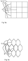
- FIG. 5 schematically shows two arrangements in which the LEDs 1 are no longer arranged in series but in a planar arrangement, wherein Fig. 5a a rectangular, in particular square arrangement.
- Fig. 5a a rectangular, in particular square arrangement.
- This can in principle be described as a series of arrangements according to the Figures 1-4 be constructed, now on both sides of their long sides of the reflector side parts 12 LEDs can be arranged.
- a hexagonal construction like in Fig. 5b is a possible preferred arrangement, since in this case a particularly large packing density can be achieved and the light distribution when approaching the LEDs surrounding reflector elements to a circle advantageously designed.
- the arrangement of the reflector side walls 12 and the holding elements 4 is conceivable, for example such that the reflector side walls 12 extend in the transverse direction of the figure, quasi as "zigzag lines" and perpendicular to the main line A of the zigzag line sections are formed as holding elements 4.
Landscapes
- Engineering & Computer Science (AREA)
- General Engineering & Computer Science (AREA)
- Microelectronics & Electronic Packaging (AREA)
- Manufacturing & Machinery (AREA)
- Fastening Of Light Sources Or Lamp Holders (AREA)
- Arrangement Of Elements, Cooling, Sealing, Or The Like Of Lighting Devices (AREA)
Description
- Die Erfindung geht aus von LED-Leuchten, die mehrere in Reihe geschaltete Light Emitting Dioden (LEDs) haben.
- Aus dem Stand der Technik sind in Reihe geschaltete LEDs bekannt, die untereinander fest verdrahtet sind.
Auf der Internetseite der Firma Relco www.relcogroup.de bzw. deren Tochterunternehmen VLM s.p.a. (www.vlm.it) und im Produktkatalog der selben Firma sind LED-Leuchten offenbart bei denen mehrere LEDs in Reihe geschaltet sind. Die LEDs sind dabei auf einer gemeinsamen Leiterplatte gruppiert und daher nicht einzeln austauschbar.
Darüber hinaus sind beim Einsatz derartiger Leuchten meistens Reflektoren zur Bündelung oder Ausrichtung des von den LEDs abgegebenen Lichts vorgesehen. Diese sind gemäß dem Stand der Technik als von der elektrischen Versorgung unabhängige Teile bekannt. DokumentUS2010/0203757 offenbart eine Leuchte gemäß dem Oberbegriff des Anspruchs 1. - Die Aufgabe der vorliegenden Erfindung ist es, eine LED-Leuchte mit mehreren in Reihe geschalteten LEDs zu schaffen, deren LEDs frei konfiguriert und ausgetauscht werden können.
Diese Aufgabe wird gelöst durch eine LED-Leuchte mit mehreren in Reihe geschalteten LEDs. Zwischen den LEDs angeordnete Stromleiter bilden dabei elastische Halteelemente für die LEDs. Die Halteelemente bilden Reflektorabschnitte. - Besonders vorteilhafte Ausgestaltungen finden sich in den abhängigen Ansprüchen.
- Bei einer besonders bevorzugten Weiterbildung sind die LEDs auf einer jeweiligen Leiterplatte angeordnet, wobei jeweils ein Halteelement - vorzugsweise über Lötpads - in elektrischem Kontakt mit zwei zueinander benachbarten Leiterplatten ist und dabei als Halteelement für diese beiden Leiterplatten dient.
- Bei einer besonders bevorzugten Weiterbildung sind die Leiterplatten entlang einer Längsachse der LED-Leuchte angeordnet. Die LED-Leuchte hat zwei Reflektorseitenteile, die sich beidseitig der Längsachse im Wesentlichen über die gesamte Leuchte erstrecken. Diese können, obwohl sie einteilig ausgebildet sind, das Licht aller LEDs reflektieren bzw. bündeln bzw. streuen.
- Wenn jedes Halteelement bzw. Reflektorabschnitt aus einem quer zur Längsachse gebogenen ursprünglich flächigen Blech gefertigt ist, ergibt sich ein gute Niederhaltfähigkeit bei einfacher Fertigung.
- Vorzugsweise ist jedes Halteelement bzw. jeder Reflektorabschnitt im Wesentlichen spiegelsymmetrisch zu einer senkrecht zur Längsachse angeordneten Querebene geformt. Dabei hat jedes Halteelement bzw. jeder Reflektorabschnitt zwei Reflexionsbereiche, die jeweils einer LED zugewandt sind. Dabei liegt ein Randabschnitt jedes Reflexionsbereiches an einer Leiterplatte an.
- Vorzugsweise sind die beiden an einer Leiterplatte anliegenden Reflexionsbereiche von der LED weg biegbar, so dass die Leiterplatte aus der erfindungsgemäßen LED-Leuchte entnehmbar ist.
- Eine vorrichtungstechnisch einfache Sicherstellung der richtigen Polung beim Einbau oder beim Austauschen der Leitplatten ergibt sich, wenn zwischen jeder Leiterplatte und einem der Reflektorseitenteile eine Positionierhilfe angeordnet ist, die ein Vorsprung sein kann, und die in eine entsprechend geformte seitliche Ausnehmung der Leiterplatte eintaucht.
- Eine vorrichtungstechnisch einfache Verbindung zwischen den Halteelementen bzw. Reflektorabschnitten und den Reflektorseitenteilen ergibt sich, wenn die Halteelemente bzw. Reflektorabschnitte jeweils zwei Vorsprünge haben, die sich quer zur Längsachse erstrecken, und die in jeweilige Ausnehmungen der Reflektorseitenteile eingesetzt sind.
- Ein einfache Kühlung mit guter Wärmeableitung von den LEDs ergibt sich, wenn die Leiterplatten über zwei Halteelemente bzw. Reflektorabschnitte gegen einen flächigen Kühlkörper vorgespannt sind. Dabei stützen sich die Halteelemente bzw. Reflektorabschnitte über die Vorsprünge in den Ausnehmungen der Reflektorseitenteile ab.
- Die Wärmeableitung wird dabei weiter verbessert, wenn zwischen dem Kühlkörper und den Leiterplatten ein flächiges flexibles Wärmeleitelement bzw. "thermal interface material" (tim) angeordnet ist.
- Zwischen den beiden Reflexionsbereichen eines Halteelements bzw. Reflektorabschnitts kann jeweils ein Steg angeordnet sein, der zwischen dem Halteelement bzw. Reflektorabschnitt und dem Kühlkörper bzw. dem "thermal interface material" (tim) eingespannt ist.
- Dabei können die Stege an einem sich im Wesentlichen entlang der Leuchte erstreckenden Gitterrahmen befestigt sein. Der Gitterrahmen liegt an dem Kühlkörper an, wobei die Leiterplatten jeweils in einer Ausnehmung des Gitterrahmens angeordnet sind.
- Es sind auch flächige Anordnungen der LEDs denkbar, indem zum Beispiel mehrere
- Im Folgenden soll die Erfindung anhand eines Ausführungsbeispiels näher erläutert werden. Die Figuren zeigen:
- Fig. 1
- einen Ausschnitt eines Ausführungsbeispiels der erfindungsgemäßen LED-Leuchte in einer perspektivischen Ansicht;
- Fig. 2
- einen Ausschnitt des Ausführungsbeispiels gemäß
Figur 1 in einem Längsschnitt; - Fig. 3
- einen Ausschnitt des Ausführungsbeispiels gemäß
Figur 1 in einem Querschnitt; - Fig. 4
- einen Ausschnitt des Ausführungsbeispiels gemäß
Figur 1 in einer Draufsicht; und - Fig. 5
- zwei Ausführungsbeispiele mit erfindungsgemäßen LED-Leuchten mit einer flächigen Anordnung der LEDs.
-
Figur 1 zeigt einen Ausschnitt eines Ausführungsbeispiels einer erfindungsgemäßen LED-Leuchte in einer perspektivischen Ansicht. Sie hat mehrere in einer Reihe angeordnete LEDs, von denen inFigur 1 nur drei LEDs 1 dargestellt sind. Jede LED 1 ist auf einer vergleichsweise kleinen Leiterplatte 2 befestigt. Die LEDs 1 sind jeweils über zwei Lötkontakte 3 elektrisch an die jeweilige Leiterplatte 2 angeschlossen. Die Leiterplatten 2 sind im Wesentlichen rechteckig geformt und in einer Reihe entlang einer (nicht dargestellten) Längsachse der LED-Leuchte zueinander beabstandet angeordnet. - Zwischen zwei benachbarten Leiterplatten 2 ist jeweils ein Halteelement 4 angeordnet.
-
Figur 2 zeigt einen Ausschnitt des Ausführungsbeispiels gemäßFigur 1 in einem Längsschnitt. Die Halteelemente 4 sind aus Blech gestanzt und gebogen und haben (in dem inFigur 2 gezeigten Schnitt) die Form eines Daches. An den beiden (inFigur 2 ) unteren Enden eines Halteelements 4 ist jeweils ein Randabschnitt 6 angeordnet. Über jeden Randabschnitt 6 wird über ein Lötpad ein Rand einer Leiterplatte 2 (inFigur 2 ) nach unten vorgespannt. Im eingebauten Zustand der erfindungsgemäßen LED-Leuchte wird diese Vorspannung meistens nach oben gerichtet sein. - In
Figur 2 unterhalb der Leiterplatten 2 sind ein flächiges Wärmeleitelement 8 und darunter ein flächiger Kühlkörper 10 angeordnet, wobei der Kühlkörper 10 auch die Funktion einer Grundplatte der erfindungsgemäßen LED-Leuchte hat. Das Wärmeleitelement 8 ist aus elastischem bzw. kompressiblen "thermal interface material" gebildet und gleicht somit Unebenheiten zwischen den Leiterplatten 2 und dem Kühlkörper 10 aus. - Im Betrieb der erfindungsgemäßen LED-Leuchte wird die Wärme der LEDs 1 über ihre Leiterplatten 2 und über das Wärmeleitelement 8 zum Kühlkörper 10 übertragen und von letzterem an die Umgebung abgegeben.
- In
Figur 2 ist ersichtlich, dass durch ein manuelles Auseinanderdrücken der beiden an einer Leiterplatte 2 anliegenden Randabschnitte 6 die Leiterplatte 2 mit der LED 1 freigegeben und somit entfernt oder ausgetauscht werden kann. Wenn die beiden Randabschnitte 6 eines einzigen Halteelements 4 zusammengedrückt werden, werden zwei zueinander benachbarte Leiterplatten 2 teilweise freigegeben. Da über die Halteelemente 4 , während sie berührt oder zusammengedrückt werden, Strom fließen kann, wird das gezeigte Ausführungsbeispiel der erfindungsgemäßen LED-Leuchte mit Safety Extra Low Voltage (SELV) betrieben. - Aus
Figur 1 ist ersichtlich, dass das Ausführungsbeispiel der erfindungsgemäßen LED-Leuchte eine Reflektoranordnung hat, die zwei Reflektorseitenteile 12 hat, wobei die Halteelemente 4 Reflektorabschnitte der Reflektoranordnung bilden. Die beiden Reflektorseitenteile 12 erstrecken sich beidseitig der Leiterplatten 2 entlang des Ausführungsbeispiels der LED-Leuchte. Durch die Reflektoranordnung wird das von der LED in zwei gegenüberliegende seitliche Richtungen abgestrahlte Licht über die Reflektorseitenteile 12 reflektiert, während das zu den beiden anderen einander gegenüberliegenden Seiten abgestrahlte Licht von Reflexionsbereichen 22 an den Flanken der Halteelemente 4 reflektiert wird. -
Figur 3 zeigt einen Ausschnitt des Ausführungsbeispiels gemäßFigur 1 in einem Querschnitt. Dabei ist ersichtlich, dass die beiden Reflektorseitenteile 12 an ihren inneren den LEDs zugewandten Seiten jeweils mehrere Ausnehmungen 14 haben, in die Vorsprünge 16 der Halteelemente 4 eingesetzt sind. Die Vorsprünge 16 erstrecken sich quer zur Längsachse der LED-Leuchte. Somit ist jedes Halteelement 4 über die beiden Vorsprünge 16 in den beiden Reflektorseitenteilen 12 gehalten. Da das inFigur 3 geschnitten dargestellte Halteelement 4 zwei (inFigur 3 nicht gezeigte) Leiterplatten 2 nach unten vorspannt, stützt sich das Halteelement 4 (inFigur 3 ) nach oben in den beiden Ausnehmungen 14 der beiden Reflektorseitenteile 12 ab. - Die Leiterplatten 2 sind an ihren Außenrändern von einem gemeinsamen Gitterrahmen umfasst, der sich entlang der LED-Leuchte erstreckt. Von dem Gitterrahmen sind in
Figur 3 nur ein und inFigur 2 nur zwei Querstreben 18 gezeigt. Die Querstreben 18 erstrecken sich quer zur Längsachse und sind zwischen zwei zueinander benachbarten Leiterplatten 2 angeordnet. Von jeder Querstrebe 18 des Gitterrahmens erstreckt sich ein flächiger Steg 20 (in den Figuren 2 und 3) nach oben. Somit ist im Innern jedes Halteelements 4 ein Steg 20 als Stütze für das Halteelement 4 angeordnet. - Beim gezeigten Ausführungsbeispiel dienen die Halteelemente 4 zum Halten der Leiterplatten 2 in der LED-Leuchte und zum Andrücken der Leiterplatten 2 an das Wärmeleitelement 8 sowie zum Weiterleiten des Stroms von einer Leiterplatte 2 zur nächsten Leiterplatte 2 und weiterhin zum Reflektieren des von der benachbarten LED 1 in ihre Richtung abgegebenen Lichts.
-
Figur 4 zeigt einen Ausschnitt des Ausführungsbeispiels gemäßFigur 1 in einer Draufsicht. Dabei ist neben den mit Bezug zu denFiguren 1 bis 3 erläuterten Teilen weiterhin in jeder Leiterplatte 2 eine seitliche Ausnehmung 24 dargestellt. In diese Ausnehmung 24 erstreckt sich eine entsprechend geformte Positionierhilfe 26. Dadurch ist sichergestellt, dass jede Leiterplatte 2 beim Einbau bzw. beim Austausch nur mit korrekter Polung zwischen die beiden Reflektorseitenteile 12 und zwischen den beiden Halteelementen 4 eingesetzt werden kann. -
Figur 5 zeigt schematisch zwei Anordnungen, bei denen die LEDs 1 nicht mehr in Reihe sondern in einer flächigen Anordnung angeordnet sind, wobeiFig. 5a eine rechteckige, insbesondere quadratische Anordnung. Diese kann prinzipiell als eine Aneinanderreihung von Anordnungen gemäß derFiguren 1-4 aufgebaut sein, wobei nun beidseits ihrer Längsseiten der Reflektorseitenteile 12 LEDs angeordnet sein können. Auch ein hexagonaler Aufbau, wie inFig. 5b gezeigt, ist eine mögliche bevorzugte Anordnung, da hierbei eine besonders große Packungsdichte erzielt werden kann und die Lichtverteilung bei Annäherung der die LEDs umgebenden Reflektorelemente an eine Kreis vorteilhaft gestaltet. Die Anordnung der Reflektorseitenwände 12 und der Haltelemente 4 ist dabei beispielsweise dergestalt denkbar, dass die Reflektorseitenwände 12 in Querrichtung der Figur verlaufen, quasi als "Zickzack-Linien" und die zur Hauptlinie A der Zickzack-Linie senkrechten Abschnitte als Haltelemente 4 ausgebildet sind.
Claims (11)
- LED-Leuchte mit mehreren in Reihe geschalteten LEDs (1) wobei zwischen den LEDs (1) angeordnete Stromleiter elastische Halteelemente (4) für die LEDs (1) bilden, dadurch gekennzeichnet, dass die Halteelemente (4) Reflektorabschnitte bilden.
- LED-Leuchte nach Anspruch 1, wobei die LEDs (1) auf einer jeweiligen Leiterplatte (2) angeordnet sind, und wobei jeweils ein Halteelement (4) für zwei Leiterplatten (2) dient und in elektrischem Kontakt mit den beiden Leiterplatten (2) ist.
- LED-Leuchte nach Anspruch 2, wobei die Leiterplatten (2) entlang einer Längsachse angeordnet sind, und wobei zwei Reflektorseitenteile (12) vorgesehen sind, die sich beidseitig der Längsachse entlang dieser erstrecken.
- LED-Leuchte nach Anspruch 3, wobei jedes Halteelement (4) aus einem quer zur Längsachse gebogenen Blech gefertigt ist.
- LED-Leuchte nach Anspruch 3 oder 4, wobei jedes Halteelement (4) spiegelsymmetrisch zu einer senkrecht zur Längsachse angeordneten Querebene (A-A) geformt ist, und wobei jedes Halteelement (4) zwei Reflexionsbereiche (22) hat, die jeweils einer LED (1) zugewandt sind, und wobei ein Randabschnitt (6) jedes Reflexionsbereiches (22) an einer Leiterplatte (2) anliegt.
- LED-Leuchte nach Anspruch 5, wobei die beiden Reflexionsbereiche (22) von der jeweiligen LED (1) weg biegbar sind, so dass die Leiterplatte (2) entnehmbar ist.
- LED-Leuchte nach einem der Ansprüche 3 bis 6, wobei zwischen jeder Leiterplatte (2) und einem der Reflektorseitenteile (12) eine Positionierhilfe (26) angeordnet ist, der in eine entsprechend geformte seitliche Ausnehmung (24) der Leiterplatte (2) eintaucht.
- LED-Leuchte nach einem der Ansprüche 3 bis 7, wobei die Halteelemente (4) jeweils zwei Vorsprünge (16) haben, die sich quer zur Längsachse erstrecken, und die in jeweilige Ausnehmungen (14) der Reflektorseitenteile (12) eingesetzt sind.
- LED-Leuchte nach Anspruch 8, wobei jede Leiterplatte (2) über zwei Halteelemente (4) gegen einen flächigen Kühlkörper (10) vorgespannt ist, und wobei die Halteelemente (4) über die Vorsprünge (16) in den Ausnehmungen (14) der Reflektorseitenteile (12) abgestützt sind.
- LED-Leuchte nach Anspruch 5 und 9, wobei zwischen den beiden Reflexionsbereichen (22) eines Halteelements (4) jeweils ein Steg (20) angeordnet ist, der zwischen dem Halteelement (4) und dem Kühlkörper (10) eingespannt ist.
- LED-Leuchte nach Anspruch 10, wobei die Stege an einem Gitterrahmen befestigt sind, der an dem Kühlkörper anliegt, und wobei die Leiterplatten jeweils in einer Ausnehmung des Gitterrahmens angeordnet sind.
Applications Claiming Priority (1)
| Application Number | Priority Date | Filing Date | Title |
|---|---|---|---|
| DE102013219333.5A DE102013219333A1 (de) | 2013-09-25 | 2013-09-25 | LED-Leuchte |
Publications (2)
| Publication Number | Publication Date |
|---|---|
| EP2854489A1 EP2854489A1 (de) | 2015-04-01 |
| EP2854489B1 true EP2854489B1 (de) | 2017-11-08 |
Family
ID=51492855
Family Applications (1)
| Application Number | Title | Priority Date | Filing Date |
|---|---|---|---|
| EP14183847.4A Not-in-force EP2854489B1 (de) | 2013-09-25 | 2014-09-05 | LED-Leuchte |
Country Status (2)
| Country | Link |
|---|---|
| EP (1) | EP2854489B1 (de) |
| DE (1) | DE102013219333A1 (de) |
Families Citing this family (2)
| Publication number | Priority date | Publication date | Assignee | Title |
|---|---|---|---|---|
| CN108307583A (zh) * | 2017-09-18 | 2018-07-20 | 潘尚法 | 一种双pcb夹焊led的灯条和灯条屏 |
| DE102018131402A1 (de) * | 2018-12-07 | 2020-06-10 | Trilux Gmbh & Co. Kg | Entblendeter Linsenstabilisator |
Family Cites Families (13)
| Publication number | Priority date | Publication date | Assignee | Title |
|---|---|---|---|---|
| US6566824B2 (en) * | 2001-10-16 | 2003-05-20 | Teledyne Lighting And Display Products, Inc. | Flexible lighting segment |
| CN101852349B (zh) * | 2005-12-22 | 2012-08-29 | 松下电器产业株式会社 | 具有led的照明器具 |
| GB2442013A (en) * | 2006-09-21 | 2008-03-26 | Hogarth Fine Art Ltd | A lamp with repositionable LEDs |
| DE102008052869B4 (de) * | 2008-09-15 | 2014-06-26 | Siteco Beleuchtungstechnik Gmbh | Leuchte mit LED-Tragschiene |
| US7892022B2 (en) * | 2009-02-06 | 2011-02-22 | Tyco Electronics Corporation | Jumper connector for a lighting assembly |
| DE202009002978U1 (de) * | 2009-03-04 | 2010-07-22 | Zumtobel Lighting Gmbh | Optisches Element für LED-Leuchten |
| EP2295847A2 (de) * | 2009-09-15 | 2011-03-16 | Broll Systemtechnik KG | Leuchte, insbesondere Tunnelleuchte |
| JP5517239B2 (ja) * | 2009-11-10 | 2014-06-11 | 日本航空電子工業株式会社 | コネクタ |
| AT509626B1 (de) * | 2010-02-15 | 2012-04-15 | Hierzer Andreas | Modulares led beleuchtungssystem mit partieller lichtstärkenanpassung |
| GB2484713A (en) * | 2010-10-21 | 2012-04-25 | Optovate Ltd | Illumination apparatus |
| DE102011005047B3 (de) * | 2011-03-03 | 2012-09-06 | Osram Ag | Leuchtvorrichtung |
| KR101082587B1 (ko) * | 2011-07-07 | 2011-11-17 | 주식회사지엘에스 | 엘이디를 이용한 조명장치 |
| WO2013066920A2 (en) * | 2011-11-03 | 2013-05-10 | Cooledge Lighting, Inc. | Broad-area lighting systems |
-
2013
- 2013-09-25 DE DE102013219333.5A patent/DE102013219333A1/de not_active Ceased
-
2014
- 2014-09-05 EP EP14183847.4A patent/EP2854489B1/de not_active Not-in-force
Also Published As
| Publication number | Publication date |
|---|---|
| DE102013219333A1 (de) | 2015-03-26 |
| EP2854489A1 (de) | 2015-04-01 |
Similar Documents
| Publication | Publication Date | Title |
|---|---|---|
| EP2375128B1 (de) | Leuchte mit LEDs und den LEDs zugeordneten Linsen | |
| DE102011076613B4 (de) | LED-Leuchte und Verfahren zur Herstellung der LED-Leuchte | |
| DE202010006197U1 (de) | LED-Lampe | |
| EP2854489B1 (de) | LED-Leuchte | |
| WO2013171305A1 (de) | Verbindungsmodul, stromversorgungsmodul und verbindungssatz für leuchtbänder | |
| DE102009042339A1 (de) | Lichtleiste | |
| EP2721342B1 (de) | Beleuchtungseinrichtung | |
| EP3056805A1 (de) | Langgestreckte optik für led-module | |
| DE102010042193A1 (de) | LED-Leuchte mit gebogenem Lichtabgebebereich | |
| DE202009009802U1 (de) | Leuchten-Moduleinheit | |
| EP3008381A1 (de) | Led-modul mit berührungsschutzelement | |
| EP1552983A1 (de) | Leuchte, insbesondere Warnleuchte, für ein Fahrzeug | |
| EP2989380B1 (de) | Led-leuchte mit lichtleiterplatte | |
| EP3686481B1 (de) | Kühlkörper für eine led-platine | |
| EP2986899B1 (de) | Led-modul sowie anordnung zur lichtabgabe | |
| EP3214366B1 (de) | Linearleuchte und verfahren zur montage einer solchen | |
| EP3108722A1 (de) | Leiterplatte mit speziellen kupplungsbereichen | |
| DE102009007612A1 (de) | Vorrichtung zur Wärmeabfuhr und Verfahren zu ihrer Herstellung | |
| DE102011102406A1 (de) | Leuchte mit LEDs | |
| EP3088796B1 (de) | Profilschiene zur positionierung von led modulen in flächenleuchten | |
| DE102009007121A1 (de) | Gekühlte LED-Leuchte | |
| DE102009042707A1 (de) | Leuchte | |
| EP3620836A1 (de) | Dmd-modul | |
| EP2674663B1 (de) | Beleuchtungsvorrichtung | |
| WO2020114859A1 (de) | Kühlkörper für ein kraftfahrzeuglichtmodul |
Legal Events
| Date | Code | Title | Description |
|---|---|---|---|
| PUAI | Public reference made under article 153(3) epc to a published international application that has entered the european phase |
Free format text: ORIGINAL CODE: 0009012 |
|
| 17P | Request for examination filed |
Effective date: 20140905 |
|
| AK | Designated contracting states |
Kind code of ref document: A1 Designated state(s): AL AT BE BG CH CY CZ DE DK EE ES FI FR GB GR HR HU IE IS IT LI LT LU LV MC MK MT NL NO PL PT RO RS SE SI SK SM TR |
|
| AX | Request for extension of the european patent |
Extension state: BA ME |
|
| R17P | Request for examination filed (corrected) |
Effective date: 20151001 |
|
| RBV | Designated contracting states (corrected) |
Designated state(s): AL AT BE BG CH CY CZ DE DK EE ES FI FR GB GR HR HU IE IS IT LI LT LU LV MC MK MT NL NO PL PT RO RS SE SI SK SM TR |
|
| RIC1 | Information provided on ipc code assigned before grant |
Ipc: F21V 19/00 20060101ALI20161128BHEP Ipc: F21V 19/04 20060101ALI20161128BHEP Ipc: F21Y 115/10 20160101ALN20161128BHEP Ipc: H05K 3/00 20060101ALI20161128BHEP Ipc: F21S 4/28 20160101ALI20161128BHEP Ipc: F21Y 103/10 20160101ALN20161128BHEP Ipc: H05K 1/14 20060101AFI20161128BHEP Ipc: F21V 7/00 20060101ALN20161128BHEP |
|
| GRAP | Despatch of communication of intention to grant a patent |
Free format text: ORIGINAL CODE: EPIDOSNIGR1 |
|
| INTG | Intention to grant announced |
Effective date: 20170504 |
|
| GRAS | Grant fee paid |
Free format text: ORIGINAL CODE: EPIDOSNIGR3 |
|
| GRAA | (expected) grant |
Free format text: ORIGINAL CODE: 0009210 |
|
| AK | Designated contracting states |
Kind code of ref document: B1 Designated state(s): AL AT BE BG CH CY CZ DE DK EE ES FI FR GB GR HR HU IE IS IT LI LT LU LV MC MK MT NL NO PL PT RO RS SE SI SK SM TR |
|
| REG | Reference to a national code |
Ref country code: GB Ref legal event code: FG4D Free format text: NOT ENGLISH |
|
| REG | Reference to a national code |
Ref country code: CH Ref legal event code: EP Ref country code: AT Ref legal event code: REF Ref document number: 945329 Country of ref document: AT Kind code of ref document: T Effective date: 20171115 |
|
| REG | Reference to a national code |
Ref country code: IE Ref legal event code: FG4D Free format text: LANGUAGE OF EP DOCUMENT: GERMAN |
|
| REG | Reference to a national code |
Ref country code: DE Ref legal event code: R096 Ref document number: 502014006120 Country of ref document: DE |
|
| REG | Reference to a national code |
Ref country code: CH Ref legal event code: NV Representative=s name: BOVARD AG PATENT- UND MARKENANWAELTE, CH |
|
| REG | Reference to a national code |
Ref country code: NL Ref legal event code: MP Effective date: 20171108 |
|
| REG | Reference to a national code |
Ref country code: LT Ref legal event code: MG4D |
|
| PG25 | Lapsed in a contracting state [announced via postgrant information from national office to epo] |
Ref country code: FI Free format text: LAPSE BECAUSE OF FAILURE TO SUBMIT A TRANSLATION OF THE DESCRIPTION OR TO PAY THE FEE WITHIN THE PRESCRIBED TIME-LIMIT Effective date: 20171108 Ref country code: NL Free format text: LAPSE BECAUSE OF FAILURE TO SUBMIT A TRANSLATION OF THE DESCRIPTION OR TO PAY THE FEE WITHIN THE PRESCRIBED TIME-LIMIT Effective date: 20171108 Ref country code: LT Free format text: LAPSE BECAUSE OF FAILURE TO SUBMIT A TRANSLATION OF THE DESCRIPTION OR TO PAY THE FEE WITHIN THE PRESCRIBED TIME-LIMIT Effective date: 20171108 Ref country code: NO Free format text: LAPSE BECAUSE OF FAILURE TO SUBMIT A TRANSLATION OF THE DESCRIPTION OR TO PAY THE FEE WITHIN THE PRESCRIBED TIME-LIMIT Effective date: 20180208 Ref country code: ES Free format text: LAPSE BECAUSE OF FAILURE TO SUBMIT A TRANSLATION OF THE DESCRIPTION OR TO PAY THE FEE WITHIN THE PRESCRIBED TIME-LIMIT Effective date: 20171108 Ref country code: SE Free format text: LAPSE BECAUSE OF FAILURE TO SUBMIT A TRANSLATION OF THE DESCRIPTION OR TO PAY THE FEE WITHIN THE PRESCRIBED TIME-LIMIT Effective date: 20171108 |
|
| PG25 | Lapsed in a contracting state [announced via postgrant information from national office to epo] |
Ref country code: HR Free format text: LAPSE BECAUSE OF FAILURE TO SUBMIT A TRANSLATION OF THE DESCRIPTION OR TO PAY THE FEE WITHIN THE PRESCRIBED TIME-LIMIT Effective date: 20171108 Ref country code: IS Free format text: LAPSE BECAUSE OF FAILURE TO SUBMIT A TRANSLATION OF THE DESCRIPTION OR TO PAY THE FEE WITHIN THE PRESCRIBED TIME-LIMIT Effective date: 20180308 Ref country code: BG Free format text: LAPSE BECAUSE OF FAILURE TO SUBMIT A TRANSLATION OF THE DESCRIPTION OR TO PAY THE FEE WITHIN THE PRESCRIBED TIME-LIMIT Effective date: 20180208 Ref country code: LV Free format text: LAPSE BECAUSE OF FAILURE TO SUBMIT A TRANSLATION OF THE DESCRIPTION OR TO PAY THE FEE WITHIN THE PRESCRIBED TIME-LIMIT Effective date: 20171108 Ref country code: GR Free format text: LAPSE BECAUSE OF FAILURE TO SUBMIT A TRANSLATION OF THE DESCRIPTION OR TO PAY THE FEE WITHIN THE PRESCRIBED TIME-LIMIT Effective date: 20180209 Ref country code: RS Free format text: LAPSE BECAUSE OF FAILURE TO SUBMIT A TRANSLATION OF THE DESCRIPTION OR TO PAY THE FEE WITHIN THE PRESCRIBED TIME-LIMIT Effective date: 20171108 |
|
| PG25 | Lapsed in a contracting state [announced via postgrant information from national office to epo] |
Ref country code: CZ Free format text: LAPSE BECAUSE OF FAILURE TO SUBMIT A TRANSLATION OF THE DESCRIPTION OR TO PAY THE FEE WITHIN THE PRESCRIBED TIME-LIMIT Effective date: 20171108 Ref country code: SK Free format text: LAPSE BECAUSE OF FAILURE TO SUBMIT A TRANSLATION OF THE DESCRIPTION OR TO PAY THE FEE WITHIN THE PRESCRIBED TIME-LIMIT Effective date: 20171108 Ref country code: EE Free format text: LAPSE BECAUSE OF FAILURE TO SUBMIT A TRANSLATION OF THE DESCRIPTION OR TO PAY THE FEE WITHIN THE PRESCRIBED TIME-LIMIT Effective date: 20171108 Ref country code: CY Free format text: LAPSE BECAUSE OF FAILURE TO SUBMIT A TRANSLATION OF THE DESCRIPTION OR TO PAY THE FEE WITHIN THE PRESCRIBED TIME-LIMIT Effective date: 20171108 Ref country code: DK Free format text: LAPSE BECAUSE OF FAILURE TO SUBMIT A TRANSLATION OF THE DESCRIPTION OR TO PAY THE FEE WITHIN THE PRESCRIBED TIME-LIMIT Effective date: 20171108 |
|
| REG | Reference to a national code |
Ref country code: DE Ref legal event code: R097 Ref document number: 502014006120 Country of ref document: DE |
|
| PG25 | Lapsed in a contracting state [announced via postgrant information from national office to epo] |
Ref country code: SM Free format text: LAPSE BECAUSE OF FAILURE TO SUBMIT A TRANSLATION OF THE DESCRIPTION OR TO PAY THE FEE WITHIN THE PRESCRIBED TIME-LIMIT Effective date: 20171108 Ref country code: PL Free format text: LAPSE BECAUSE OF FAILURE TO SUBMIT A TRANSLATION OF THE DESCRIPTION OR TO PAY THE FEE WITHIN THE PRESCRIBED TIME-LIMIT Effective date: 20171108 |
|
| PLBE | No opposition filed within time limit |
Free format text: ORIGINAL CODE: 0009261 |
|
| STAA | Information on the status of an ep patent application or granted ep patent |
Free format text: STATUS: NO OPPOSITION FILED WITHIN TIME LIMIT |
|
| PG25 | Lapsed in a contracting state [announced via postgrant information from national office to epo] |
Ref country code: MT Free format text: LAPSE BECAUSE OF FAILURE TO SUBMIT A TRANSLATION OF THE DESCRIPTION OR TO PAY THE FEE WITHIN THE PRESCRIBED TIME-LIMIT Effective date: 20171108 |
|
| 26N | No opposition filed |
Effective date: 20180809 |
|
| PG25 | Lapsed in a contracting state [announced via postgrant information from national office to epo] |
Ref country code: SI Free format text: LAPSE BECAUSE OF FAILURE TO SUBMIT A TRANSLATION OF THE DESCRIPTION OR TO PAY THE FEE WITHIN THE PRESCRIBED TIME-LIMIT Effective date: 20171108 |
|
| REG | Reference to a national code |
Ref country code: DE Ref legal event code: R119 Ref document number: 502014006120 Country of ref document: DE |
|
| PG25 | Lapsed in a contracting state [announced via postgrant information from national office to epo] |
Ref country code: MC Free format text: LAPSE BECAUSE OF FAILURE TO SUBMIT A TRANSLATION OF THE DESCRIPTION OR TO PAY THE FEE WITHIN THE PRESCRIBED TIME-LIMIT Effective date: 20171108 |
|
| REG | Reference to a national code |
Ref country code: CH Ref legal event code: PL |
|
| GBPC | Gb: european patent ceased through non-payment of renewal fee |
Effective date: 20180905 |
|
| REG | Reference to a national code |
Ref country code: BE Ref legal event code: MM Effective date: 20180930 |
|
| REG | Reference to a national code |
Ref country code: IE Ref legal event code: MM4A |
|
| PG25 | Lapsed in a contracting state [announced via postgrant information from national office to epo] |
Ref country code: LU Free format text: LAPSE BECAUSE OF NON-PAYMENT OF DUE FEES Effective date: 20180905 |
|
| PG25 | Lapsed in a contracting state [announced via postgrant information from national office to epo] |
Ref country code: IT Free format text: LAPSE BECAUSE OF NON-PAYMENT OF DUE FEES Effective date: 20180905 Ref country code: DE Free format text: LAPSE BECAUSE OF NON-PAYMENT OF DUE FEES Effective date: 20190402 Ref country code: IE Free format text: LAPSE BECAUSE OF NON-PAYMENT OF DUE FEES Effective date: 20180905 |
|
| PG25 | Lapsed in a contracting state [announced via postgrant information from national office to epo] |
Ref country code: CH Free format text: LAPSE BECAUSE OF NON-PAYMENT OF DUE FEES Effective date: 20180930 Ref country code: LI Free format text: LAPSE BECAUSE OF NON-PAYMENT OF DUE FEES Effective date: 20180930 Ref country code: BE Free format text: LAPSE BECAUSE OF NON-PAYMENT OF DUE FEES Effective date: 20180930 Ref country code: FR Free format text: LAPSE BECAUSE OF NON-PAYMENT OF DUE FEES Effective date: 20180930 |
|
| PG25 | Lapsed in a contracting state [announced via postgrant information from national office to epo] |
Ref country code: GB Free format text: LAPSE BECAUSE OF NON-PAYMENT OF DUE FEES Effective date: 20180905 |
|
| PG25 | Lapsed in a contracting state [announced via postgrant information from national office to epo] |
Ref country code: TR Free format text: LAPSE BECAUSE OF FAILURE TO SUBMIT A TRANSLATION OF THE DESCRIPTION OR TO PAY THE FEE WITHIN THE PRESCRIBED TIME-LIMIT Effective date: 20171108 |
|
| PG25 | Lapsed in a contracting state [announced via postgrant information from national office to epo] |
Ref country code: HU Free format text: LAPSE BECAUSE OF FAILURE TO SUBMIT A TRANSLATION OF THE DESCRIPTION OR TO PAY THE FEE WITHIN THE PRESCRIBED TIME-LIMIT; INVALID AB INITIO Effective date: 20140905 Ref country code: PT Free format text: LAPSE BECAUSE OF FAILURE TO SUBMIT A TRANSLATION OF THE DESCRIPTION OR TO PAY THE FEE WITHIN THE PRESCRIBED TIME-LIMIT Effective date: 20171108 |
|
| PG25 | Lapsed in a contracting state [announced via postgrant information from national office to epo] |
Ref country code: RO Free format text: LAPSE BECAUSE OF FAILURE TO SUBMIT A TRANSLATION OF THE DESCRIPTION OR TO PAY THE FEE WITHIN THE PRESCRIBED TIME-LIMIT Effective date: 20171108 Ref country code: MK Free format text: LAPSE BECAUSE OF NON-PAYMENT OF DUE FEES Effective date: 20171108 |
|
| PG25 | Lapsed in a contracting state [announced via postgrant information from national office to epo] |
Ref country code: AL Free format text: LAPSE BECAUSE OF FAILURE TO SUBMIT A TRANSLATION OF THE DESCRIPTION OR TO PAY THE FEE WITHIN THE PRESCRIBED TIME-LIMIT Effective date: 20171108 |
|
| REG | Reference to a national code |
Ref country code: AT Ref legal event code: MM01 Ref document number: 945329 Country of ref document: AT Kind code of ref document: T Effective date: 20190905 |
|
| PG25 | Lapsed in a contracting state [announced via postgrant information from national office to epo] |
Ref country code: AT Free format text: LAPSE BECAUSE OF NON-PAYMENT OF DUE FEES Effective date: 20190905 |