EP3686341A1 - Walzenwechsel - Google Patents
Walzenwechsel Download PDFInfo
- Publication number
- EP3686341A1 EP3686341A1 EP19212472.5A EP19212472A EP3686341A1 EP 3686341 A1 EP3686341 A1 EP 3686341A1 EP 19212472 A EP19212472 A EP 19212472A EP 3686341 A1 EP3686341 A1 EP 3686341A1
- Authority
- EP
- European Patent Office
- Prior art keywords
- machine
- mounting rail
- rail
- roller
- mounting
- Prior art date
- Legal status (The legal status is an assumption and is not a legal conclusion. Google has not performed a legal analysis and makes no representation as to the accuracy of the status listed.)
- Granted
Links
Images


Classifications
-
- D—TEXTILES; PAPER
- D21—PAPER-MAKING; PRODUCTION OF CELLULOSE
- D21G—CALENDERS; ACCESSORIES FOR PAPER-MAKING MACHINES
- D21G1/00—Calenders; Smoothing apparatus
- D21G1/02—Rolls; Their bearings
- D21G1/0293—Provisions or constructions to facilitate the removal of the rolls
-
- B—PERFORMING OPERATIONS; TRANSPORTING
- B65—CONVEYING; PACKING; STORING; HANDLING THIN OR FILAMENTARY MATERIAL
- B65G—TRANSPORT OR STORAGE DEVICES, e.g. CONVEYORS FOR LOADING OR TIPPING, SHOP CONVEYOR SYSTEMS OR PNEUMATIC TUBE CONVEYORS
- B65G35/00—Mechanical conveyors not otherwise provided for
-
- B—PERFORMING OPERATIONS; TRANSPORTING
- B66—HOISTING; LIFTING; HAULING
- B66C—CRANES; LOAD-ENGAGING ELEMENTS OR DEVICES FOR CRANES, CAPSTANS, WINCHES, OR TACKLES
- B66C1/00—Load-engaging elements or devices attached to lifting or lowering gear of cranes or adapted for connection therewith for transmitting lifting forces to articles or groups of articles
- B66C1/10—Load-engaging elements or devices attached to lifting or lowering gear of cranes or adapted for connection therewith for transmitting lifting forces to articles or groups of articles by mechanical means
Definitions
- the invention relates to a roll changing device for a machine for producing and / or finishing a material web, which comprises a support rail to be positioned in the machine transversely to the web running direction and at least one transport carriage traveling along the support rail, which transports the roller to be changed out of the machine and the new roller in again.
- the invention also relates to a method for changing rolls in a machine for producing and / or refining a material web, wherein in the machine a carrier rail is positioned transversely to the direction of web travel and the roller to be changed is moved out of the machine and at least via a transport carriage traveling along the carrier rail new roller is inserted again.
- rollers which come into contact with the material web or endless belts of the machine and which have to be replaced as a result of wear or damage. All rollers, which due to their installation position cannot be lifted out of the machine directly with the help of a crane, require a special device for changing the rollers.
- a support rail running transversely to the web running direction is positioned in the machine, on which the roller is transported out of and into the machine. Since these machines are very wide and the rollers to be transported are accordingly very heavy, the mounting rail must be designed to be correspondingly stable, which also entails a relatively high weight. For example, paper machines can have widths of 10 m, which makes it difficult to insert the mounting rail.
- the fixing of the mounting rail is adapted to the special installation location in the machine and requires a wide variety of aids, such as holders, deflection rollers, brackets, counterholders, building attachments or the like.
- the installation of the mounting rails is usually very complex, since the machine beam between the foundation rails contains openings and unevenness, such as laid paper, basement, etc.
- the object of the invention is therefore to simplify the roll change.
- the object was achieved with respect to the device in that the mounting rail is coupled to a mounting rail running in parallel, which for mounting and dismounting the mounting rail in the machine can be displaced along the mounting rail and partly beyond the mounting rail.
- the mounting rail is installed in the machine using the mounting rail.
- the mounting rail is brought together with the mounting rail on one side of the machine, preferably the driver's side, into the intended installation position and aligned perpendicular to the web running direction.
- the mounting rail is then moved along the mounting rail, partly beyond the mounting rail, into the machine transversely to the web running direction and fastened in the machine. Then the mounting rail can simply be pushed into the machine along the mounting rail and fixed there.
- roller is transported in a known manner from and into the machine by means of transport carriages along the mounting rail.
- a crane can be used to deposit the roller in and to receive the roller from the storage device of the transport vehicle.
- This crane can also be used to at least partially support the mounting rail during assembly and disassembly in the machine.
- the mounting rail has a coupling element for attachment to a crane at least at one end, preferably the end facing away from the machine and a central region lying between the ends.
- the coupling in the middle area is advantageously used for positioning the mounting rail on the machine side and the coupling at the end after the end of the mounting rail has been fastened in the machine.
- a transport carriage For safe storage of the roller, a transport carriage should be assigned to each roller end, which can also be coupled to one another if necessary.
- the mounting rail should be slidably mounted in the mounting rail.
- the support rail is supported on the frame or the foundation of the machine during the roller change and that the transport carriage with the roller above it travels along the support rail or that the support rail travels via connecting elements during the roller change is attached above her existing chair parts and a suitably adapted transport carriage with the roller hanging underneath it runs along and under the mounting rail.
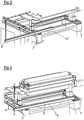
- the machine has a drive-side and a driver-side frame 7, which is supported on the machine foundation.
- the ends of a multiplicity of rollers 6 are each mounted in the drive-side and the driver-side frame 7.
- these are primarily guide rolls for deflecting the material web or endless belts of the machine, such as press felt, transfer belt or dryer fabric.
- rollers 6 wear relatively quickly because of the high stress and machine speeds of 2,000 m / min and more. If the rollers 6 are not freely accessible to a crane from above, a support rail 2 must be installed in the machine to change the rollers transverse to the web running direction 1.
- roller 6 to be changed can be moved transversely to the web running direction 1 and the new roller 6 can be guided into the machine.
- the ends of the roller 6 are each held by a transport carriage 4, 5 which are guided in the mounting rail 2 and are movable along the latter.
- the mounting of the mounting rail 2 is supported by a crane, the mounting rail 2 having a coupling element 8 for attachment to the crane at the end pointing away from the machine prior to mounting and a central region lying between the ends.
- the mounting rail 2 according to Figure 1 Held by the crane via the coupling element 8 of the central area, the support rail 2 is aligned perpendicular to the web running direction 1 and partially inserted into the machine at the corresponding point.
- a mounting rail 3 is slidably mounted therein.
- This mounting rail 3, which runs parallel to the mounting rail 2, can thus be displaced telescopically for mounting and dismounting the mounting rail 2 in the machine along the mounting rail 2 and partly beyond the mounting rail 2.
- the mounting rail 3 After the partial insertion of the mounting rail 2 into the machine according to Figure 2 pulled the mounting rail 3 out of the mounting rail 2 to the opposite, preferably the drive-side frame 7 and fastened there. If necessary, the assembly rail 3 can be pulled out using a cable winch. Since the mounting rail 2 is also supported on the driver-side frame 7, the mounting rail 2 is already sufficiently fixed so that the crane can be moved around.
- the mounting rail 2 is then pushed into the machine along the mounting rail 3 to the opposite frame 7. To make this easier, the end of the mounting rail 2 that still protrudes from the machine should be raised slightly by the crane.
- the support rail 2 is supported on the frame 7 of the machine during the roll change.
- a transport carriage 4, 5 is assigned to each roller end.
- roller 6 to be changed can simply be guided out of the machine and the new roller 6 into the machine.
- the mounting rail 2 it is also possible for the mounting rail 2 to be fastened to parts of the frame 7 above it via connecting elements during the roll change. This then means that the transport carriages 4, 5 travel with the roller 6 hanging below them along and under the mounting rail 2.
- the roller changing device can thus be used universally and does not require any major adjustments to the special installation situation.
Landscapes
- Engineering & Computer Science (AREA)
- Mechanical Engineering (AREA)
- Replacement Of Web Rolls (AREA)
- Carriers, Traveling Bodies, And Overhead Traveling Cranes (AREA)
Abstract
Description
- Die Erfindung betrifft eine Walzenwechselvorrichtung für eine Maschine zur Herstellung und/oder Veredlung einer Materialbahn, welche eine in der Maschine quer zur Bahnlaufrichtung zu positionierende Tragschiene sowie wenigstens einen entlang der Tragschiene fahrenden Transportwagen umfasst, der die zu wechselnde Walze aus der Maschine heraus- und die neue Walze wieder hineinführt.
- Die Erfindung betrifft ebenso ein Verfahren zum Walzenwechsel bei einer Maschine zur Herstellung und/oder Veredlung einer Materialbahn, wobei in der Maschine eine Tragschiene quer zur Bahnlaufrichtung positioniert und über wenigstens einen entlang der Tragschiene fahrenden Transportwagen die zu wechselnde Walze aus der Maschine heraus- und die neue Walze wieder hineingeführt wird.
- In derartigen Maschinen befinden sich viele Walzen, die mit der Materialbahn oder endlos umlaufenden Bändern der Maschine in Kontakt kommen und infolge Verschleiß oder Beschädigung gewechselt werden müssen.
Alle Walzen, welche auf Grund ihrer Einbauposition nicht direkt mit Hilfe eines Kranes aus der Maschine gehoben werden können, benötigen für den Walzenwechsel eine spezielle Vorrichtung.
Im Allgemeinen wird dabei in der Maschine eine quer zur Bahnlaufrichtung verlaufende Tragschiene positioniert, an der die Walze aus und in die Maschine transportiert wird.
Da diese Maschinen sehr breit und die zu transportierenden Walzen dementsprechend auch sehr schwer sind, muss die Tragschiene entsprechend stabil gestaltet sein, was ebenso ein relativ hohes Gewicht mit sich bringt.
Beispielsweise können Papiermaschinen durchaus Breiten von 10 m aufweisen, was das Einführen der Tragschiene schwierig gestaltet.
Darüber hinaus ist die Fixierung der Tragschiene an den speziellen Einbauort in der Maschine angepasst und erfordert dabei die unterschiedlichsten Hilfsmittel, wie Halter, Umlenkrollen, Konsolen, Gegenhalter, Gebäudeanbauten o.ä. - Das Einbringen der Tragschien ist meist sehr aufwendig, da der Maschinenbalken zwischen den Fundamentschienen Öffnungen und Unebenheiten z.B. Bütten, Keller usw. enthält.
- Die Aufgabe der Erfindung ist es daher den Walzenwechsel zu vereinfachen.
- Erfindungsgemäß wurde die Aufgabe hinsichtlich der Vorrichtung dadurch gelöst, dass die Tragschiene mit einer parallel verlaufenden Montageschiene gekoppelt ist, welche zur Montage und Demontage der Tragschiene in der Maschine entlang der Tragschiene und teilweise über die Tragschiene hinaus verschiebbar ist.
Die Montage der Tragschiene in der Maschine erfolgt dabei mit Hilfe der Montageschiene. Zu Beginn wird die Tragschiene gemeinsam mit der Montageschiene an einer Seite der Maschine, vorzugsweise der Führerseite in die vorgesehene Einbauposition gebracht und dabei senkrecht zur Bahnlaufrichtung ausgerichtet.
Anschließend wird die Montageschiene entlang der Tragschiene, teilweise über die Tragschiene hinaus in die Maschine quer zur Bahnlaufrichtung verschoben und in der Maschine befestigt. Danach kann die Tragschiene einfach entlang der Montageschiene in die Maschine geschoben und dort fixiert werden.
Diese Lösung ist universell einsetzbar und erfordert kaum spezielle Anpassungen an die Einbauposition.
Der Transport der Walze erfolgt in bekannter Weise mittels Transportwagen entlang der Tragschiene aus und in die Maschine. Bei der Ablage der Walze in und der Aufnahme der Walze aus der Lagervorrichtung des Transportwagens kann ein Kran zum Einsatz kommen. - Dieser Kran kann auch dazu genutzt werden, die Tragschiene während der Montage und Demontage in der Maschine zumindest teilweise zu tragen. Hierzu ist es vorteilhaft, wenn die Tragschiene zumindest an einem, vorzugsweise dem der Maschine abgewandten Ende und einem zwischen den Enden liegenden mittleren Bereich ein Koppelelement für die Befestigung an einem Kran besitzt.
Die Kopplung im mittleren Bereich erfolgt dabei mit Vorteil zur Positionierung der Tragschiene an der Maschinenseite und die Kopplung am Ende nach der Befestigung des Endes der Montageschiene in der Maschine. - Zur sicheren Lagerung der Walze sollte jedem Walzenende jeweils ein Transportwagen zugeordnet sein, welche bei Bedarf auch miteinander gekoppelt sein können.
- Im Interesse einer einfachen Kopplung und Verschiebbarkeit sollte die Montageschiene in der Tragschiene verschiebbar gelagert sein.
- Je nach Einbausituation der Walze kann es vorteilhaft sein, dass sich die Tragschiene während des Walzenwechsels auf der Stuhlung oder dem Fundament der Maschine abstützt und der Transportwagen mit der über ihm liegenden Walze auf der Tragschiene entlang fährt oder dass die Tragschiene während des Walzenwechsels über Verbindungselemente an über ihr vorhandenen Stuhlungsteilen befestigt ist und ein entsprechend angepasster Transportwagen mit der unter ihm hängenden Walze an und unter der Tragschiene entlang fährt.
- Nachfolgend soll die Erfindung an zwei Ausführungsbeispielen näher erläutert werden. In der beigefügten Zeichnung zeigen die
Figuren 1 bis 5 den Ablauf bei der Positionierung einer Tragschiene 2 für einen Walzenwechsel in einer Papiermaschine. - Die Maschine besitzt eine trieb- und eine führerseitige Stuhlung 7, welche sich auf dem Maschinenfundament abstützt. Neben verschiedenen Einbauten wie dem Stoffauflauf, Formerleisten, Dampfblaskasten, Saugkästen usw. sind in der triebseitigen und der führerseitigen Stuhlung 7 jeweils die Enden einer Vielzahl von Walzen 6 gelagert. Neben Press- und Glättwalzen sind dies vor allem Leitwalzen zur Umlenkung der Materialbahn oder endlos umlaufender Bänder der Maschine, wie Pressfilz, Transferband oder Trockensieb.
- Diese Walzen 6 verschleißen wegen der hohen Beanspruchung und Maschinengeschwindigkeiten von 2.000 m/min und mehr relativ schnell. Sind die Walzen 6 von oben einem Kran nicht frei zugänglich, so muss für einen Walzenwechsel in der Maschine quer zur Bahnlaufrichtung 1 eine Tragschiene 2 montiert werden.
- Entlang dieser Tragschiene 2 kann die zu wechselnde Walze 6 quer zur Bahnlaufrichtung 1 aus und die neue Walze 6 in die Maschine geführt werden. Dabei werden die Enden der Walze 6 von je einem Transportwagen 4,5 gehalten, welche in der Tragschiene 2 geführt und entlang dieser bewegbar sind.
- Unterstützt wird die Montage der Tragschiene 2 von einem Kran, wobei die Tragschiene 2 an dem, vor der Montage von der Maschine wegweisendem Ende und einem zwischen den Enden liegenden mittleren Bereich ein Koppelelement 8 für die Befestigung an dem Kran besitzt.
- Zu Beginn wird die Tragschiene 2 gemäß
Figur 1 über das Koppelelement 8 des mittleren Bereiches vom Kran gehalten, die Tragschiene 2 senkrecht zur Bahnlaufrichtung 1 ausgerichtet und an der entsprechenden Stelle der Maschine teilweise in diese eingeführt. - Um die Montage der Tragschiene 2 zu vereinfachen, ist in dieser eine Montageschiene 3 verschiebbar gelagert. Diese parallel zur Tragschiene 2 verlaufende Montageschiene 3 kann so zur Montage und Demontage der Tragschiene 2 in der Maschine entlang der Tragschiene 2 und teilweise über die Tragschiene 2 hinaus teleskopähnlich verschoben werden.
- Nach dem teilweisen Einführen der Tragschiene 2 in die Maschine wird gemäß
Figur 2 die Montageschiene 3 aus der Tragschiene 2 heraus zur gegenüberliegenden, vorzugsweise der triebseitigen Stuhlung 7 gezogen und dort befestigt. Bei Bedarf kann das Herausziehen der Montageschiene 3 mittels Seilwinde erfolgen.
Da sich die Tragschiene 2 dabei auch auf der führerseitigen Stuhlung 7 abstützt, ist die Tragschiene 2 bereits ausreichend fixiert, so dass der Kran umgehängt werden kann. - Wie in
Figur 3 zu erkennen, wird der Kran nun mit dem Koppelelement 8 verbunden, welches sich an dem von der Maschine wegweisenden Ende der Tragschiene 2 befindet. - Mit Hilfe des Kranes und/oder bei Bedarf auch unter Zuhilfenahme einer Seilwinde wird die Tragschiene 2 anschließend entlang der Montageschiene 3 bis zur gegenüberliegenden Stuhlung 7 in die Maschine geschoben. Um dies zu erleichtern, sollte das noch aus der Maschine ragende Ende der Tragschiene 2 vom Kran geringfügig angehoben werden.
- Hat die Tragschiene 2 ihre Endposition gemäß
Figur 4 erreicht, so kann diese über Verbindungselemente an der Stuhlung 7 befestigt werden. Außerdem wird der Kran abgehängt. - In den
Figuren 1 bis 5 stützt sich die Tragschiene 2 während des Walzenwechsels auf der Stuhlung 7 der Maschine ab. Wie inFigur 5 gezeigt, ist dabei jedem Walzenende jeweils ein Transportwagen 4,5 zugeordnet. - Diese Transportwagen 4,5 fahren mit der über der Tragschiene 2 liegenden Walze 6 auf und entlang der Tragschiene 2.
- So kann die zu wechselnde Walze 6 einfach aus der Maschine und die neue Walze 6 in die Maschine geführt werden.
- Alternativ ist es allerdings auch möglich, dass die Tragschiene 2 während des Walzenwechsels über Verbindungselemente an über ihr vorhandenen Teilen der Stuhlung 7 befestigt wird. Dies bedeutet dann, dass die Transportwagen 4,5 mit der unter ihnen hängenden Walze 6 an und unter der Tragschiene 2 entlang fahren.
- Die Walzenwechselvorrichtung ist so universell einsetzbar und erfordert keine größeren Anpassungen an die spezielle Einbausituation.
Claims (10)
- Walzenwechselvorrichtung für eine Maschine zur Herstellung und/oder Veredlung einer Materialbahn, welche eine in der Maschine quer zur Bahnlaufrichtung (1) zu positionierende Tragschiene (2) sowie wenigstens einen entlang der Tragschiene (2) fahrenden Transportwagen (4,5) umfasst, der die zu wechselnde Walze (6) aus der Maschine heraus- und die neue Walze (6) wieder hineinführt, dadurch gekennzeichnet,
dass die Tragschiene (2) mit einer parallel verlaufenden Montageschiene (3) gekoppelt ist, welche zur Montage und Demontage der Tragschiene (2) in der Maschine entlang der Tragschiene (2) und teilweise über die Tragschiene (2) hinaus verschiebbar ist. - Vorrichtung nach Anspruch 1,
dadurch gekennzeichnet,
dass die Montageschiene (3) in der Tragschiene (2) verschiebbar gelagert ist. - Vorrichtung nach Anspruch 1 oder 2,
dadurch gekennzeichnet,
dass jedem Walzenende jeweils ein Transportwagen (4,5) zugeordnet ist. - Vorrichtung nach einem der vorherigen Ansprüche,
dadurch gekennzeichnet,
dass sich die Tragschiene (2) während des Walzenwechsels auf der Stuhlung (7) oder dem Fundament der Maschine abstützt. - Vorrichtung nach einem der Ansprüche 1 bis 3,
dadurch gekennzeichnet,
dass die Tragschiene (2) während des Walzenwechsels über Verbindungselemente an über ihr vorhandenen Stuhlungsteilen befestigt ist. - Vorrichtung nach einem der vorherigen Ansprüche,
dadurch gekennzeichnet,
dass die Tragschiene (2) zumindest an einem Ende und einem zwischen den Enden liegenden mittleren Bereich ein Koppelelement (8) für die Befestigung an einem Kran besitzt. - Verfahren zum Walzenwechsel bei einer Maschine zur Herstellung und/oder Veredlung einer Materialbahn, wobei in der Maschine eine Tragschiene (2) quer zur Bahnlaufrichtung (1) positioniert und über wenigstens einen entlang der Tragschiene (2) fahrenden Transportwagen (4,5) die zu wechselnde Walze (6) aus der Maschine heraus- und die neue Walze (6) wieder hineingeführt wird, insbesondere nach einem der vorhergehenden Ansprüche, dadurch gekennzeichnet,
dass die Tragschiene (2) mit einer parallel verlaufenden Montageschiene (3) gekoppelt ist, welche zur Montage der Tragschiene (2) in der Maschine entlang der Tragschiene (2), teilweise über die Tragschiene (2) hinaus in die Maschine quer zur Bahnlaufrichtung (1) verschoben und in der Maschine befestigt wird und die Tragschiene (2) anschließend entlang der Montageschiene (3) in die Maschine geschoben wird. - Verfahren nach Anspruch 7,
dadurch gekennzeichnet,
dass die Tragschiene (2) während der Montage und Demontage in der Maschine zumindest teilweise von einem Kran getragen wird. - Verfahren nach Anspruch 7 oder 8,
dadurch gekennzeichnet,
dass sich die Tragschiene (2) während des Walzenwechsels auf der Stuhlung (7) oder dem Fundament der Maschine abstützt und der Transportwagen (4,5) mit der über ihm liegenden Walze (6) auf der Tragschiene (2) fährt. - Verfahren nach Anspruch 7 oder 8,
dadurch gekennzeichnet,
dass die Tragschiene (2) während des Walzenwechsels über Verbindungselemente an über ihr vorhandenen Stuhlungsteilen befestigt ist und der Transportwagen (4,5) mit der unter ihm hängenden Walze (6) an und unter der Tragschiene (2) fährt.
Applications Claiming Priority (1)
| Application Number | Priority Date | Filing Date | Title |
|---|---|---|---|
| DE102019101807.2A DE102019101807A1 (de) | 2019-01-25 | 2019-01-25 | Walzenwechsel |
Publications (2)
| Publication Number | Publication Date |
|---|---|
| EP3686341A1 true EP3686341A1 (de) | 2020-07-29 |
| EP3686341B1 EP3686341B1 (de) | 2021-09-15 |
Family
ID=68732884
Family Applications (1)
| Application Number | Title | Priority Date | Filing Date |
|---|---|---|---|
| EP19212472.5A Active EP3686341B1 (de) | 2019-01-25 | 2019-11-29 | Walzenwechsel |
Country Status (3)
| Country | Link |
|---|---|
| EP (1) | EP3686341B1 (de) |
| CN (1) | CN111483776B (de) |
| DE (1) | DE102019101807A1 (de) |
Families Citing this family (1)
| Publication number | Priority date | Publication date | Assignee | Title |
|---|---|---|---|---|
| FI131269B1 (fi) * | 2023-12-08 | 2025-01-17 | Valmet Technologies Oy | Telanvaihtolaite ja menetelmä telan poistamiseksi kuiturainakoneesta |
Citations (2)
| Publication number | Priority date | Publication date | Assignee | Title |
|---|---|---|---|---|
| US3244090A (en) * | 1964-09-01 | 1966-04-05 | Perkins & Son Inc B F | Calender |
| WO2001061107A1 (en) * | 2000-02-16 | 2001-08-23 | Metso Paper, Inc. | Method and device for calendering paper, comprising a heatable roll |
Family Cites Families (11)
| Publication number | Priority date | Publication date | Assignee | Title |
|---|---|---|---|---|
| JP3394847B2 (ja) * | 1995-05-10 | 2003-04-07 | 株式会社カイジョー | 部品搬送装置 |
| WO2002057543A1 (en) * | 2001-01-19 | 2002-07-25 | Metso Paper Karlstad Aktiebolag | Method for lifting and lifting arrangement for performing of said method |
| DE10312705B3 (de) * | 2003-03-21 | 2004-09-30 | Voith Paper Patent Gmbh | Kalander und Verfahren zum Ausbauen einer Unterwalze aus einem Kalander |
| CN2661647Y (zh) * | 2003-11-20 | 2004-12-08 | 孙付江 | 垂起犁式卸料装置 |
| CN101125611A (zh) * | 2007-09-11 | 2008-02-20 | 王树生 | 同步式悬挂输送机 |
| CN203889614U (zh) * | 2014-06-03 | 2014-10-22 | 江苏甬金金属科技有限公司 | 一种换辊托架 |
| CN205471090U (zh) * | 2016-03-19 | 2016-08-17 | 天津天弘精工传动机械科技股份有限公司 | 直线光轴输送架 |
| CN205471057U (zh) * | 2016-03-19 | 2016-08-17 | 天津天弘精工传动机械科技股份有限公司 | 直线光轴输送结构 |
| CN206665557U (zh) * | 2016-11-29 | 2017-11-24 | 福建宏旺实业有限公司 | 换辊车 |
| CN207551223U (zh) * | 2017-11-22 | 2018-06-29 | 临沂矿业集团菏泽煤电有限公司 | 一种输送带支撑辊的在线更换装置 |
| CN207645231U (zh) * | 2017-12-08 | 2018-07-24 | 鞍钢集团矿业有限公司 | 用于更换皮带托辊时所使用的支撑器 |
-
2019
- 2019-01-25 DE DE102019101807.2A patent/DE102019101807A1/de not_active Withdrawn
- 2019-11-29 EP EP19212472.5A patent/EP3686341B1/de active Active
- 2019-12-23 CN CN201911335134.8A patent/CN111483776B/zh active Active
Patent Citations (2)
| Publication number | Priority date | Publication date | Assignee | Title |
|---|---|---|---|---|
| US3244090A (en) * | 1964-09-01 | 1966-04-05 | Perkins & Son Inc B F | Calender |
| WO2001061107A1 (en) * | 2000-02-16 | 2001-08-23 | Metso Paper, Inc. | Method and device for calendering paper, comprising a heatable roll |
Also Published As
| Publication number | Publication date |
|---|---|
| EP3686341B1 (de) | 2021-09-15 |
| CN111483776B (zh) | 2022-08-19 |
| DE102019101807A1 (de) | 2020-07-30 |
| CN111483776A (zh) | 2020-08-04 |
Similar Documents
| Publication | Publication Date | Title |
|---|---|---|
| DE69620089T2 (de) | Wickelverfahren und Wickelmaschine | |
| EP3464716B1 (de) | Maschine zur entwässerung und trocknung einer faserstoffbahn | |
| EP3250750B1 (de) | Verfahren und vorrichtung zur herstellung von nassgelegten vliesstoffen | |
| AT505818A2 (de) | Verfahren und anordnung bei einer abrollvorrichtung fur eine faserbahn | |
| EP3686341B1 (de) | Walzenwechsel | |
| DE3916740C2 (de) | Textilmaschine mit verstellbarer Glättwalzenanordnung | |
| EP0997415A1 (de) | Wickelmaschine | |
| DE3330423C2 (de) | ||
| DE102019120924A1 (de) | Maschine und Verfahren zum Wechseln einer Bespannung in einer Papiermaschine | |
| DE102006001050A1 (de) | Wechselvorrichtung | |
| DE19882820B4 (de) | Verfahren und Vorrichtung zum Wechseln eines Rundfilzes | |
| DE10150820A1 (de) | Maschine zur Herstellung oder Behandlung einer Materialbahn | |
| AT511026A2 (de) | Vorrichtung und verfahren zum wickeln einer faserbahn | |
| DE20307581U1 (de) | Wickelmaschine zum kontinuierlichen Aufwickeln einer laufenden Materialbahn | |
| DE102009002077A1 (de) | Wickelmaschine zum Aufwickeln einer Materialbahn auf einen Wickelkern | |
| EP1870515B1 (de) | Maschinenstuhlung | |
| DE3100522C2 (de) | Walzenpresse | |
| DE69909083T2 (de) | Verfahren zum wickeln einer papier- oder kartonbahn und wickler für eine papier- oder kartonbahn | |
| DE2214595C3 (de) | Verfahren und Vorrichtung zum Entfernen einer endlosen genadelten Textilbahn aus einer Nadelmaschine | |
| EP3030712A1 (de) | Anordnung zum spannen eines formiersiebes einer papiermaschine | |
| DE102006000324A1 (de) | Anordnung und Verfahren zum Wechseln eines endlosen Bandes oder dergleichen in einer Papier- oder Kartonmaschine oder Nachbehandlungsmaschine | |
| EP3138806B1 (de) | Plattform für arbeiten an kraftfahrzeugen | |
| DE102010001081A1 (de) | Arbeitsbühneneinheit und Faserbahnmaschine | |
| DE102018119381A1 (de) | Pressanordnung | |
| DE1561651C3 (de) | Vorrichtung zum Satinieren von Papier- und Kartonbahnen |
Legal Events
| Date | Code | Title | Description |
|---|---|---|---|
| PUAI | Public reference made under article 153(3) epc to a published international application that has entered the european phase |
Free format text: ORIGINAL CODE: 0009012 |
|
| STAA | Information on the status of an ep patent application or granted ep patent |
Free format text: STATUS: THE APPLICATION HAS BEEN PUBLISHED |
|
| AK | Designated contracting states |
Kind code of ref document: A1 Designated state(s): AL AT BE BG CH CY CZ DE DK EE ES FI FR GB GR HR HU IE IS IT LI LT LU LV MC MK MT NL NO PL PT RO RS SE SI SK SM TR |
|
| AX | Request for extension of the european patent |
Extension state: BA ME |
|
| STAA | Information on the status of an ep patent application or granted ep patent |
Free format text: STATUS: REQUEST FOR EXAMINATION WAS MADE |
|
| 17P | Request for examination filed |
Effective date: 20210129 |
|
| RBV | Designated contracting states (corrected) |
Designated state(s): AL AT BE BG CH CY CZ DE DK EE ES FI FR GB GR HR HU IE IS IT LI LT LU LV MC MK MT NL NO PL PT RO RS SE SI SK SM TR |
|
| GRAP | Despatch of communication of intention to grant a patent |
Free format text: ORIGINAL CODE: EPIDOSNIGR1 |
|
| STAA | Information on the status of an ep patent application or granted ep patent |
Free format text: STATUS: GRANT OF PATENT IS INTENDED |
|
| RIC1 | Information provided on ipc code assigned before grant |
Ipc: D21G 1/02 20060101AFI20210610BHEP |
|
| INTG | Intention to grant announced |
Effective date: 20210624 |
|
| GRAS | Grant fee paid |
Free format text: ORIGINAL CODE: EPIDOSNIGR3 |
|
| GRAA | (expected) grant |
Free format text: ORIGINAL CODE: 0009210 |
|
| STAA | Information on the status of an ep patent application or granted ep patent |
Free format text: STATUS: THE PATENT HAS BEEN GRANTED |
|
| AK | Designated contracting states |
Kind code of ref document: B1 Designated state(s): AL AT BE BG CH CY CZ DE DK EE ES FI FR GB GR HR HU IE IS IT LI LT LU LV MC MK MT NL NO PL PT RO RS SE SI SK SM TR |
|
| REG | Reference to a national code |
Ref country code: CH Ref legal event code: EP |
|
| REG | Reference to a national code |
Ref country code: DE Ref legal event code: R096 Ref document number: 502019002295 Country of ref document: DE |
|
| REG | Reference to a national code |
Ref country code: IE Ref legal event code: FG4D Free format text: LANGUAGE OF EP DOCUMENT: GERMAN |
|
| REG | Reference to a national code |
Ref country code: AT Ref legal event code: REF Ref document number: 1430613 Country of ref document: AT Kind code of ref document: T Effective date: 20211015 |
|
| REG | Reference to a national code |
Ref country code: FI Ref legal event code: FGE |
|
| REG | Reference to a national code |
Ref country code: LT Ref legal event code: MG9D |
|
| REG | Reference to a national code |
Ref country code: NL Ref legal event code: MP Effective date: 20210915 |
|
| PG25 | Lapsed in a contracting state [announced via postgrant information from national office to epo] |
Ref country code: LT Free format text: LAPSE BECAUSE OF FAILURE TO SUBMIT A TRANSLATION OF THE DESCRIPTION OR TO PAY THE FEE WITHIN THE PRESCRIBED TIME-LIMIT Effective date: 20210915 Ref country code: BG Free format text: LAPSE BECAUSE OF FAILURE TO SUBMIT A TRANSLATION OF THE DESCRIPTION OR TO PAY THE FEE WITHIN THE PRESCRIBED TIME-LIMIT Effective date: 20211215 Ref country code: HR Free format text: LAPSE BECAUSE OF FAILURE TO SUBMIT A TRANSLATION OF THE DESCRIPTION OR TO PAY THE FEE WITHIN THE PRESCRIBED TIME-LIMIT Effective date: 20210915 Ref country code: NO Free format text: LAPSE BECAUSE OF FAILURE TO SUBMIT A TRANSLATION OF THE DESCRIPTION OR TO PAY THE FEE WITHIN THE PRESCRIBED TIME-LIMIT Effective date: 20211215 Ref country code: RS Free format text: LAPSE BECAUSE OF FAILURE TO SUBMIT A TRANSLATION OF THE DESCRIPTION OR TO PAY THE FEE WITHIN THE PRESCRIBED TIME-LIMIT Effective date: 20210915 Ref country code: SE Free format text: LAPSE BECAUSE OF FAILURE TO SUBMIT A TRANSLATION OF THE DESCRIPTION OR TO PAY THE FEE WITHIN THE PRESCRIBED TIME-LIMIT Effective date: 20210915 |
|
| PG25 | Lapsed in a contracting state [announced via postgrant information from national office to epo] |
Ref country code: LV Free format text: LAPSE BECAUSE OF FAILURE TO SUBMIT A TRANSLATION OF THE DESCRIPTION OR TO PAY THE FEE WITHIN THE PRESCRIBED TIME-LIMIT Effective date: 20210915 Ref country code: GR Free format text: LAPSE BECAUSE OF FAILURE TO SUBMIT A TRANSLATION OF THE DESCRIPTION OR TO PAY THE FEE WITHIN THE PRESCRIBED TIME-LIMIT Effective date: 20211216 |
|
| PG25 | Lapsed in a contracting state [announced via postgrant information from national office to epo] |
Ref country code: IS Free format text: LAPSE BECAUSE OF FAILURE TO SUBMIT A TRANSLATION OF THE DESCRIPTION OR TO PAY THE FEE WITHIN THE PRESCRIBED TIME-LIMIT Effective date: 20220115 Ref country code: SM Free format text: LAPSE BECAUSE OF FAILURE TO SUBMIT A TRANSLATION OF THE DESCRIPTION OR TO PAY THE FEE WITHIN THE PRESCRIBED TIME-LIMIT Effective date: 20210915 Ref country code: SK Free format text: LAPSE BECAUSE OF FAILURE TO SUBMIT A TRANSLATION OF THE DESCRIPTION OR TO PAY THE FEE WITHIN THE PRESCRIBED TIME-LIMIT Effective date: 20210915 Ref country code: RO Free format text: LAPSE BECAUSE OF FAILURE TO SUBMIT A TRANSLATION OF THE DESCRIPTION OR TO PAY THE FEE WITHIN THE PRESCRIBED TIME-LIMIT Effective date: 20210915 Ref country code: PT Free format text: LAPSE BECAUSE OF FAILURE TO SUBMIT A TRANSLATION OF THE DESCRIPTION OR TO PAY THE FEE WITHIN THE PRESCRIBED TIME-LIMIT Effective date: 20220117 Ref country code: PL Free format text: LAPSE BECAUSE OF FAILURE TO SUBMIT A TRANSLATION OF THE DESCRIPTION OR TO PAY THE FEE WITHIN THE PRESCRIBED TIME-LIMIT Effective date: 20210915 Ref country code: NL Free format text: LAPSE BECAUSE OF FAILURE TO SUBMIT A TRANSLATION OF THE DESCRIPTION OR TO PAY THE FEE WITHIN THE PRESCRIBED TIME-LIMIT Effective date: 20210915 Ref country code: ES Free format text: LAPSE BECAUSE OF FAILURE TO SUBMIT A TRANSLATION OF THE DESCRIPTION OR TO PAY THE FEE WITHIN THE PRESCRIBED TIME-LIMIT Effective date: 20210915 Ref country code: EE Free format text: LAPSE BECAUSE OF FAILURE TO SUBMIT A TRANSLATION OF THE DESCRIPTION OR TO PAY THE FEE WITHIN THE PRESCRIBED TIME-LIMIT Effective date: 20210915 Ref country code: CZ Free format text: LAPSE BECAUSE OF FAILURE TO SUBMIT A TRANSLATION OF THE DESCRIPTION OR TO PAY THE FEE WITHIN THE PRESCRIBED TIME-LIMIT Effective date: 20210915 Ref country code: AL Free format text: LAPSE BECAUSE OF FAILURE TO SUBMIT A TRANSLATION OF THE DESCRIPTION OR TO PAY THE FEE WITHIN THE PRESCRIBED TIME-LIMIT Effective date: 20210915 |
|
| REG | Reference to a national code |
Ref country code: DE Ref legal event code: R097 Ref document number: 502019002295 Country of ref document: DE |
|
| PG25 | Lapsed in a contracting state [announced via postgrant information from national office to epo] |
Ref country code: MC Free format text: LAPSE BECAUSE OF FAILURE TO SUBMIT A TRANSLATION OF THE DESCRIPTION OR TO PAY THE FEE WITHIN THE PRESCRIBED TIME-LIMIT Effective date: 20210915 |
|
| PLBE | No opposition filed within time limit |
Free format text: ORIGINAL CODE: 0009261 |
|
| STAA | Information on the status of an ep patent application or granted ep patent |
Free format text: STATUS: NO OPPOSITION FILED WITHIN TIME LIMIT |
|
| PG25 | Lapsed in a contracting state [announced via postgrant information from national office to epo] |
Ref country code: LU Free format text: LAPSE BECAUSE OF NON-PAYMENT OF DUE FEES Effective date: 20211129 Ref country code: DK Free format text: LAPSE BECAUSE OF FAILURE TO SUBMIT A TRANSLATION OF THE DESCRIPTION OR TO PAY THE FEE WITHIN THE PRESCRIBED TIME-LIMIT Effective date: 20210915 Ref country code: BE Free format text: LAPSE BECAUSE OF NON-PAYMENT OF DUE FEES Effective date: 20211130 |
|
| REG | Reference to a national code |
Ref country code: BE Ref legal event code: MM Effective date: 20211130 |
|
| 26N | No opposition filed |
Effective date: 20220616 |
|
| PG25 | Lapsed in a contracting state [announced via postgrant information from national office to epo] |
Ref country code: SI Free format text: LAPSE BECAUSE OF FAILURE TO SUBMIT A TRANSLATION OF THE DESCRIPTION OR TO PAY THE FEE WITHIN THE PRESCRIBED TIME-LIMIT Effective date: 20210915 |
|
| PG25 | Lapsed in a contracting state [announced via postgrant information from national office to epo] |
Ref country code: IE Free format text: LAPSE BECAUSE OF NON-PAYMENT OF DUE FEES Effective date: 20211129 |
|
| PG25 | Lapsed in a contracting state [announced via postgrant information from national office to epo] |
Ref country code: FR Free format text: LAPSE BECAUSE OF NON-PAYMENT OF DUE FEES Effective date: 20211130 |
|
| PG25 | Lapsed in a contracting state [announced via postgrant information from national office to epo] |
Ref country code: IT Free format text: LAPSE BECAUSE OF FAILURE TO SUBMIT A TRANSLATION OF THE DESCRIPTION OR TO PAY THE FEE WITHIN THE PRESCRIBED TIME-LIMIT Effective date: 20210915 |
|
| PG25 | Lapsed in a contracting state [announced via postgrant information from national office to epo] |
Ref country code: CY Free format text: LAPSE BECAUSE OF FAILURE TO SUBMIT A TRANSLATION OF THE DESCRIPTION OR TO PAY THE FEE WITHIN THE PRESCRIBED TIME-LIMIT Effective date: 20210915 |
|
| REG | Reference to a national code |
Ref country code: CH Ref legal event code: PL |
|
| PG25 | Lapsed in a contracting state [announced via postgrant information from national office to epo] |
Ref country code: LI Free format text: LAPSE BECAUSE OF NON-PAYMENT OF DUE FEES Effective date: 20221130 Ref country code: HU Free format text: LAPSE BECAUSE OF FAILURE TO SUBMIT A TRANSLATION OF THE DESCRIPTION OR TO PAY THE FEE WITHIN THE PRESCRIBED TIME-LIMIT; INVALID AB INITIO Effective date: 20191129 Ref country code: CH Free format text: LAPSE BECAUSE OF NON-PAYMENT OF DUE FEES Effective date: 20221130 |
|
| PG25 | Lapsed in a contracting state [announced via postgrant information from national office to epo] |
Ref country code: MK Free format text: LAPSE BECAUSE OF FAILURE TO SUBMIT A TRANSLATION OF THE DESCRIPTION OR TO PAY THE FEE WITHIN THE PRESCRIBED TIME-LIMIT Effective date: 20210915 |
|
| GBPC | Gb: european patent ceased through non-payment of renewal fee |
Effective date: 20231129 |
|
| PG25 | Lapsed in a contracting state [announced via postgrant information from national office to epo] |
Ref country code: MT Free format text: LAPSE BECAUSE OF FAILURE TO SUBMIT A TRANSLATION OF THE DESCRIPTION OR TO PAY THE FEE WITHIN THE PRESCRIBED TIME-LIMIT Effective date: 20210915 |
|
| PG25 | Lapsed in a contracting state [announced via postgrant information from national office to epo] |
Ref country code: GB Free format text: LAPSE BECAUSE OF NON-PAYMENT OF DUE FEES Effective date: 20231129 |
|
| PG25 | Lapsed in a contracting state [announced via postgrant information from national office to epo] |
Ref country code: GB Free format text: LAPSE BECAUSE OF NON-PAYMENT OF DUE FEES Effective date: 20231129 |
|
| PGFP | Annual fee paid to national office [announced via postgrant information from national office to epo] |
Ref country code: DE Payment date: 20241121 Year of fee payment: 6 |
|
| PGFP | Annual fee paid to national office [announced via postgrant information from national office to epo] |
Ref country code: FI Payment date: 20241122 Year of fee payment: 6 |
|
| PGFP | Annual fee paid to national office [announced via postgrant information from national office to epo] |
Ref country code: AT Payment date: 20241121 Year of fee payment: 6 |
|
| PG25 | Lapsed in a contracting state [announced via postgrant information from national office to epo] |
Ref country code: TR Free format text: LAPSE BECAUSE OF FAILURE TO SUBMIT A TRANSLATION OF THE DESCRIPTION OR TO PAY THE FEE WITHIN THE PRESCRIBED TIME-LIMIT Effective date: 20210915 |