EP3686146B1 - Commande de déplacement d'une cabine d'ascenseur - Google Patents
Commande de déplacement d'une cabine d'ascenseur Download PDFInfo
- Publication number
- EP3686146B1 EP3686146B1 EP19153740.6A EP19153740A EP3686146B1 EP 3686146 B1 EP3686146 B1 EP 3686146B1 EP 19153740 A EP19153740 A EP 19153740A EP 3686146 B1 EP3686146 B1 EP 3686146B1
- Authority
- EP
- European Patent Office
- Prior art keywords
- elevator car
- elevator
- hoistway
- switch
- predefined
- Prior art date
- Legal status (The legal status is an assumption and is not a legal conclusion. Google has not performed a legal analysis and makes no representation as to the accuracy of the status listed.)
- Active
Links
- 238000000034 method Methods 0.000 claims description 20
- 230000004913 activation Effects 0.000 claims description 6
- 230000001133 acceleration Effects 0.000 claims description 4
- 230000003287 optical effect Effects 0.000 claims description 4
- 230000003213 activating effect Effects 0.000 description 8
- 238000009434 installation Methods 0.000 description 8
- 238000012544 monitoring process Methods 0.000 description 5
- 239000000463 material Substances 0.000 description 4
- 241000282412 Homo Species 0.000 description 2
- 229910000831 Steel Inorganic materials 0.000 description 2
- 238000010586 diagram Methods 0.000 description 2
- 238000012423 maintenance Methods 0.000 description 2
- 229920000642 polymer Polymers 0.000 description 2
- 239000010959 steel Substances 0.000 description 2
- 241000282326 Felis catus Species 0.000 description 1
- 230000009286 beneficial effect Effects 0.000 description 1
- 239000011248 coating agent Substances 0.000 description 1
- 238000000576 coating method Methods 0.000 description 1
- 230000002542 deteriorative effect Effects 0.000 description 1
- 238000011900 installation process Methods 0.000 description 1
Images


Classifications
-
- B—PERFORMING OPERATIONS; TRANSPORTING
- B66—HOISTING; LIFTING; HAULING
- B66B—ELEVATORS; ESCALATORS OR MOVING WALKWAYS
- B66B5/00—Applications of checking, fault-correcting, or safety devices in elevators
- B66B5/0006—Monitoring devices or performance analysers
- B66B5/0018—Devices monitoring the operating condition of the elevator system
-
- B—PERFORMING OPERATIONS; TRANSPORTING
- B66—HOISTING; LIFTING; HAULING
- B66B—ELEVATORS; ESCALATORS OR MOVING WALKWAYS
- B66B5/00—Applications of checking, fault-correcting, or safety devices in elevators
- B66B5/0043—Devices enhancing safety during maintenance
- B66B5/005—Safety of maintenance personnel
- B66B5/0056—Safety of maintenance personnel by preventing crushing
-
- B—PERFORMING OPERATIONS; TRANSPORTING
- B66—HOISTING; LIFTING; HAULING
- B66B—ELEVATORS; ESCALATORS OR MOVING WALKWAYS
- B66B1/00—Control systems of elevators in general
- B66B1/24—Control systems with regulation, i.e. with retroactive action, for influencing travelling speed, acceleration, or deceleration
- B66B1/28—Control systems with regulation, i.e. with retroactive action, for influencing travelling speed, acceleration, or deceleration electrical
- B66B1/30—Control systems with regulation, i.e. with retroactive action, for influencing travelling speed, acceleration, or deceleration electrical effective on driving gear, e.g. acting on power electronics, on inverter or rectifier controlled motor
-
- B—PERFORMING OPERATIONS; TRANSPORTING
- B66—HOISTING; LIFTING; HAULING
- B66B—ELEVATORS; ESCALATORS OR MOVING WALKWAYS
- B66B1/00—Control systems of elevators in general
- B66B1/34—Details, e.g. call counting devices, data transmission from car to control system, devices giving information to the control system
- B66B1/3415—Control system configuration and the data transmission or communication within the control system
- B66B1/3423—Control system configuration, i.e. lay-out
-
- B—PERFORMING OPERATIONS; TRANSPORTING
- B66—HOISTING; LIFTING; HAULING
- B66B—ELEVATORS; ESCALATORS OR MOVING WALKWAYS
- B66B1/00—Control systems of elevators in general
- B66B1/34—Details, e.g. call counting devices, data transmission from car to control system, devices giving information to the control system
- B66B1/3415—Control system configuration and the data transmission or communication within the control system
- B66B1/3446—Data transmission or communication within the control system
-
- B—PERFORMING OPERATIONS; TRANSPORTING
- B66—HOISTING; LIFTING; HAULING
- B66B—ELEVATORS; ESCALATORS OR MOVING WALKWAYS
- B66B1/00—Control systems of elevators in general
- B66B1/34—Details, e.g. call counting devices, data transmission from car to control system, devices giving information to the control system
- B66B1/3492—Position or motion detectors or driving means for the detector
-
- B—PERFORMING OPERATIONS; TRANSPORTING
- B66—HOISTING; LIFTING; HAULING
- B66B—ELEVATORS; ESCALATORS OR MOVING WALKWAYS
- B66B17/00—Hoistway equipment
- B66B17/12—Counterpoises
-
- B—PERFORMING OPERATIONS; TRANSPORTING
- B66—HOISTING; LIFTING; HAULING
- B66B—ELEVATORS; ESCALATORS OR MOVING WALKWAYS
- B66B19/00—Mining-hoist operation
-
- B—PERFORMING OPERATIONS; TRANSPORTING
- B66—HOISTING; LIFTING; HAULING
- B66B—ELEVATORS; ESCALATORS OR MOVING WALKWAYS
- B66B5/00—Applications of checking, fault-correcting, or safety devices in elevators
- B66B5/0006—Monitoring devices or performance analysers
- B66B5/0018—Devices monitoring the operating condition of the elevator system
- B66B5/0031—Devices monitoring the operating condition of the elevator system for safety reasons
-
- B—PERFORMING OPERATIONS; TRANSPORTING
- B66—HOISTING; LIFTING; HAULING
- B66B—ELEVATORS; ESCALATORS OR MOVING WALKWAYS
- B66B5/00—Applications of checking, fault-correcting, or safety devices in elevators
- B66B5/0043—Devices enhancing safety during maintenance
- B66B5/005—Safety of maintenance personnel
- B66B5/0056—Safety of maintenance personnel by preventing crushing
- B66B5/0068—Safety of maintenance personnel by preventing crushing by activating the safety brakes when the elevator car exceeds a certain upper or lower position in the elevator shaft
-
- B—PERFORMING OPERATIONS; TRANSPORTING
- B66—HOISTING; LIFTING; HAULING
- B66B—ELEVATORS; ESCALATORS OR MOVING WALKWAYS
- B66B5/00—Applications of checking, fault-correcting, or safety devices in elevators
- B66B5/02—Applications of checking, fault-correcting, or safety devices in elevators responsive to abnormal operating conditions
-
- B—PERFORMING OPERATIONS; TRANSPORTING
- B66—HOISTING; LIFTING; HAULING
- B66B—ELEVATORS; ESCALATORS OR MOVING WALKWAYS
- B66B5/00—Applications of checking, fault-correcting, or safety devices in elevators
- B66B5/0006—Monitoring devices or performance analysers
- B66B5/0018—Devices monitoring the operating condition of the elevator system
- B66B5/0025—Devices monitoring the operating condition of the elevator system for maintenance or repair
Definitions
- the invention relates to a method of controlling movement of an elevator car within a hoistway of an elevator system.
- the invention further relates to an elevator system comprising a controller which is configured for employing such a method.
- An elevator system typically comprises at least one elevator car moving along a hoistway extending between a plurality of landings, and an elevator drive configured for driving the elevator car.
- a controller is configured for controlling the elevator drive. This in particular includes limiting the movement of the elevator car to a predefined range between an upper and lower limit. The upper and lower limits are set providing sufficient space above and below the elevator car in order to prevent humans, in particular mechanics working within the hoistway, from being squeezed between the elevator car and the upper or lower ends of the hoistway.
- JP 2007 153476 A discloses a terminal position manual operation device for an elevator.
- the device is provided with an upper final limit switch, an upper direction limiting limit switch and a limit switch for security of upper manual operation, which are provided in the uppermost part of a hoistway, respectively; a lower final limit switch, a lower direction limiting limit switch and a limit switch for security of lower manual operation, which are provided in the lowermost part of the hoistway, respectively; a limit switch cam provided on an elevator car; and a personal computer for maintenance connected to an elevator control device. Setting operation of the limit switch short-circuiting operation mode from the personal computer for maintenance enables manual operation in the terminal position. Manual operation is limited by the limit switches for security of manual operation.
- EP 3 401 260 A1 discloses an elevator overrun systems having a first body arranged to be fixedly mounted to a portion of an elevator system or elevator shaft, a second body positioned within the first body and movable from a deployed state to a retracted state relative to the first body, and a limit switch located at a distal end of the second body.
- the limit switch is configured to interact with a component of an elevator system to prevent movement of an elevator car.
- the elevator car may be used as a tool for transporting material to the different landings.
- the controller is usually not yet adjusted to the specific dimensions of the elevator system. Instead, the elevator drive is operated manually for moving the elevator car to the desired position(s). In such a situation, there is a considerable risk that the elevator car is moved too close to one of the ends of the hoistway so that it does not provide a sufficiently large safe space for a human being present within the hoistway.
- a method of controlling movement of an elevator car within a hoistway of an elevator system includes: detecting an activation of a switch and moving the elevator car in a predetermined direction after the switch has been activated and/or while the switch is activated. While the elevator car is moving, the current position of the elevator car within the hoistway is determined and the determined position of the elevator car is compared with at least one predefined positional limit. It in particular is checked whether the determined position corresponds to or is above a predefined upper positional limit or corresponds to or falls below a predefined lower positional limit. In case the determined position corresponds to or is beyond a predefined positional limit, the movement of the elevator car is stopped. In a following step, it is detected whether the switch is activatec again. In case the switch is activated again, the movement of the elevator car is restarted for moving the elevator car further in the predetermined direction.
- Exemplary embodiments further include an elevator systerr comprising a hoistway extending between a plurality of landings; an elevator car configured for moving along the hoistway between the plurality of landings; an elevator drive configured for driving the elevator car; a position determining system (“position reference system”) configured for determining the current position of the elevator car within the hoistway; at least one switch; and an elevator controller.
- an elevator systerr comprising a hoistway extending between a plurality of landings; an elevator car configured for moving along the hoistway between the plurality of landings; an elevator drive configured for driving the elevator car; a position determining system (“position reference system”) configured for determining the current position of the elevator car within the hoistway; at least one switch; and an elevator controller.
- the elevator controller is configured for detecting activation of the at least one switch; controlling the elevator drive to move the elevator car in a predetermined direction after the switch has been activated; while the elevator car is moving: determining the current position of the elevator car within the hoistway and comparing the determined position of the elevator car with at least one predefined positional limit; causing the elevator drive to stop the movement of the elevator car if the determined position is at or beyond a predefined positional limit; and controlling the elevator drive to start moving the elevator car further in the predetermined direction in case the at least one switch is activated again,
- the predefined positional limit is an upper positional limit which is set in a predefined upper distance from a preset uppermost position of the elevator car, and the uppermost position of the elevator car is readjusted according to the position of the elevator car in case the elevator car is moved above the previously set uppermost position of the elevator car; and/or the predefined positional limit is a lower positional limit which is set in a predefined lower distance from a preset lowermost position of the elevator car, and the lowermost position of the elevator car is readjusted according to the position of the elevator car in case the elevator car is moved below the previously set lowermost position of the elevator car.
- a method of controlling movement of an elevator car within a hoistway of an elevator system according to an exemplary embodiment of the invention and an elevator system according to an exemplary embodiment of the invention allow moving the elevator car safely, in particular during an installation phase of the elevator system, when the elevator system is operated manually, for example for transporting material between different landings.
- an upper positional limit allows restricting the movement of the elevator car close to an upper end of the hoistway in order to provide a safe space large enough for a mechanic being present on top of the elevator car.
- a lower positional limit allows restricting the movement of the elevator car close to a lower end of the hoistway in order to provide a safe space large enough for a mechanic being present at the lower end, in particular within a pit, of the hoistway.
- the position of the elevator car within the hoistway may be determined repeatedly or continuously, and the determined position of the elevator car may be compared with the at least one predefined positional limit repeatedly or continuously as well.
- the predefined upper and lower distances may be equal to each other.
- the uppermost position of the elevator car may be readjusted according to the position of the elevator car in case the elevator car is moved above the previously set uppermost position of the elevator car.
- the lowermost position of the elevator car may be readjusted according to the position of the elevator car in case the elevator car is moved below the previously set lowermost position of the elevator car.
- Readjusting the uppermost / lowermost position of the elevator car in case the elevator car is moved above/ below the previously set uppermost / lowermost position of the elevator car allows employing a method according to an exemplary embodiment of the invention without performing a dedicated calibration run for adjusting the elevator controller to the respective elevator system. This facilitates and allows to speed-up the installation process of the elevator system.
- a method may include issuing an alarm signal in case the elevator car is moved to or beyond a predefined positional limit in order to notify the person operating the movement of the elevator car that the elevator car has been moved to or beyond the predefined positional limit.
- the alarm signal may be an optical and/or an acoustic alarm signal.
- At least one switch may be arranged inside the elevator car, it in particular may be integrated with an elevator car control panel provided inside the elevator car.
- At least one switch may be arranged outside the elevator car, in particular on top of the elevator car, in order to allow a mechanic to control the movement of the elevator car from outside the elevator car.
- At least one switch may be arranged at at least one of the landings, e.g. within a landing control panel, and/or at a lower end, in particular within a pit, of the hoistway.
- the position determining system may be an absolute position determining system configured for detecting and/or determining an absolute position of the elevator car within the hoistway.
- the position determining system in particular may include a coded tape extending along the length of the hoistway and a position sensor configured for interacting with the coded tape.
- An absolute position determining system allows determining the current position of the elevator car within the hoistway with high reliability and accuracy.
- the position determining system may include a position sensor which is configured for determining the current position of the elevator car within the hoistway by detecting and integrating velocities and/or accelerations of the elevator car.
- a position sensor configured for determining the current position of the elevator car within the hoistway by detecting and integrating velocities and/or accelerations of the elevator car may be provided at comparatively low costs as it does not need a coded tape extending over the whole length of the hoistway.
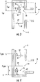
- the elevator system 2 includes an elevator car 60 movably arranged within a hoistway 4 extending between a plurality of landings 10.
- the elevator car 60 in particular is movable in a longitudinal (vertical) direction along a plurality of car guide members 14, such as guide rails, extending along the vertical direction of the hoistway 4. Only one of said car guide members 14 is depicted in Figure 1 .
- elevator car 60 Although only one elevator car 60 is shown in Figure 1 , the skilled person understands that exemplary embodiments of the invention may include elevator systems 2 including a plurality of elevator cars 60 moving in one or more hoistways 4.
- the elevator car 60 is movably suspended by means of a tension member 3.
- the tension member 3 for example a rope or belt, is connected to an elevator drive 5, which is configured for driving the tension member 3 in order to move the elevator car 60 along the height of the hoistway 4 between the plurality of landings 10, which are located on different floors.
- the exemplary embodiment shown in Figure 1 uses a 1:1 roping for suspending the elevator car 60.
- the skilled person easily understands that the type of the roping is not essential for the invention and that different kinds of roping, e.g. a 2:1 roping or a 4:1 roping may be used as well.
- the tension member 3 may be a rope, e.g. a steel wire rope, or a belt.
- the tension member 3 may be uncoated or may have a coating, e.g. in the form of a polymer jacket.
- the tension member 3 may be a belt comprising a plurality of polymer coated steel cords (not shown).
- the elevator system 2 may have a traction drive including a traction sheave for driving the tension member 3.
- the elevator system 2 may be an elevator system 2 without a tension member 3.
- the elevator system 2 also may comprise e.g. a hydraulic drive or a linear drive.
- the elevator system 2 may have a machine room (not shown) or it may be a machine room-less elevator system 2.
- the elevator system 2 further includes a counterweight 19 attached to the tension member 3 and configured for moving concurrently and in opposite direction with respect to the elevator car 60 along at least one counterweight guide member 15.
- a counterweight 19 attached to the tension member 3 and configured for moving concurrently and in opposite direction with respect to the elevator car 60 along at least one counterweight guide member 15.
- Each landing 10 is provided with a landing door 11, and the elevator car 60 is provided with a corresponding elevator car door 12 for allowing passengers to transfer between a landing 10 and the interior of the elevator car 60 when the elevator car 60 is positioned at the respective landing 10.
- the elevator drive 5 is controlled by an elevator controller 6 for moving the elevator car 60 along the hoistway 4 between the different landings 10.
- Input to the elevator controller 6 may be provided via landing control panels 7a, which are provided on each landing 10 close to the landing doors 11, and/or via an elevator car control panel 7b, which is provided inside the elevator car 60.
- Each of the control panels 7a, 7b may comprise at least one switch 8a, 8b which allows providing input to the elevator controller 6.
- the landing control panels 7a and the elevator car control panel 7b may be connected to the elevator controller 6 by means of electric wires, which are not shown in Figure 1 , in particular by an electric bus, or by means of wireless data connections.
- the elevator car 60 is equipped with at least one position determining system 20, which is configured for detecting the position of the elevator car 60 within the hoistway 4.
- the position determining system 20 may be an absolute position determining system 20, including a position sensor 22 configured for interacting with a coded tape 24 extending along the length of the hoistway 4.
- the position determining system 20 may comprise a position sensor 22 which is configured for determining the current position of the elevator car 60 within the hoistway 4 by detecting and integrating velocities and/or accelerations of the elevator car 60.
- the elevator car 60 may be used for transporting material to the different landings 10.
- an automatic control of the elevator system 2 limiting the movement of the elevator car 60 at both ends 41, 42 of the hoistway 4 usually is not yet implemented. Instead, the movement of the elevator car 60 is controlled manually by a mechanic 70 (see Figures 3 and 4 ).
- the mechanic 70 may operate switches 8a, 8b provided at the control panels 7a, 7b. Additional switches 8c, 8d allowing the mechanic 70 to manually control the movement of the elevator car 60 may be provided within the hoistway 4, in particular within a pit 44 at a lower end 42 of the hoistway 4, and/or outside, in particular on top or below, the elevator car 60.
- Figure 3 illustrates the elevator car 60 in an uppermost position close to a top T of the hoistway 4
- Figure 4 illustrates the elevator car 60 in a lowermost position close to a bottom B of the hoistway 4.
- a (virtual) top T and a (virtual) bottom B of the hoistway 4 are set within the elevator controller 6. The details of setting the top T and the bottom B of the hoistway 4 are discussed in more detail further below.
- step 110 movement of the elevator car 60 is started by the mechanic 70 by activating one of the switches 8a-8d.
- each of the switches 8a-8d may be configured so that two hands are necessary for activating the respective switch 8a-8d. For example, it may be necessary to press two buttons simultaneously for activating the respective switch 8a-8d.
- the elevator controller 6 is configured for monitoring the current position of the elevator car 60 (step 120) based on a positional signal provided by the position sensor 22 while the elevator car 60 is moving.
- the elevator controller 6 in particular may be configured for monitoring the current position of the elevator car 60 continuously or repeatedly.
- step 200 the current position of the elevator car 60 as indicated by the positional signal is compared with a predefined upper positional limit L UP (cf. Figure 3 ).
- the current position of the elevator car 60 is compared in step 300 with a predefined lower positional limit L LOW (cf. Figure 4 ) while the elevator car 60 is moving.
- the elevator car 60 is allowed to continue its movement and the controller 6 circulates through steps 120, 200, 300 monitoring the current position of the elevator car 60 with respect to the upper and lower positional limits L UP , L LOW. .
- the controller 6 determines in step 200 that the current position of the elevator car 60, in particular the position of the position sensor 22 of to the elevator car 60, reaches or exceeds the predefined upper positional limit L UP , i.e. in case the elevator car 60 is moved upwards to or beyond the predefined upper positional limit L UP , the movement of the elevator car 60 is stopped (step 210).
- an acoustic and/or optical alarm signal is generated (step 215) for notifying the mechanic 70 controlling the movement of the elevator car 60 that the upper positional limit L UP has been reached or exceeded.
- step 220 it is checked (in step 220) whether the mechanic 70 has activated one of the switches 8a-8d, in particular the same switch 8a-8d or the same combination of switches 8a-8d which he has activated for starting the movement of the elevator car 60, again.
- the same switch 8a-8d is activated again, movement of the elevator car 60 is restarted (step 230) for moving the elevator car 60 in the same direction as before, i.e. upwards in the present example.
- the elevator controller 6 in particular may be configured for causing the elevator drive 5 to move the elevator car 60 upwards as long as the switch 8a-8d or the combination of switches 8a-8d is activated, e.g. as long as a button or a combination of buttons configured for activating the switch 8a-8d is pressed.
- Such a configuration allows the mechanic 70 to move the elevator car 60 to a desired position close to the upper end 41 (top T) of the hoistway 4 (see Figure 3 ).
- the elevator car 60 may be moved in the opposite direction, i.e. downwards, by activating another switch 8a-8d or another combination of switches 8a-8d (step 110). In this case, the method 100 continues with monitoring the current position of the elevator car 60 (step 120).
- step 310 In case the current position of the elevator car 60 falls below the predefined lower positional limit L LOW , i.e. the elevator car 60 moves to or below the predefined lower positional limit L LOW , the movement of the elevator car 60 is stopped (step 310).
- an acoustic and/or optical alarm signal is generated (in step 315) for notifying the mechanic 70 controlling the movement of the elevator car 60 that the elevator car 60 has moved to or below the lower positional limit L LOW .
- step 320 it is checked (in step 320) whether the mechanic 70 has activated a switch 8a-8d, in particular the same switch 8a-8d or the same combination of switches 8a-8d which he has activated for starting the movement of the elevator car 60 in the beginning, again.
- a switch 8a-8d in particular the same switch 8a-8d or the same combination of switches 8a-8d which he has activated for starting the movement of the elevator car 60 in the beginning, again.
- movement of the elevator car 60 is restarted (step 330) for moving the elevator car 60 in the same direction as before, i.e. downwards in the present example.
- the elevator car 60 in particular may continue to move downwards as long as the respective switch 8a-8d or the same combination of switches 8a-8d is activated. This allows the mechanic 70 to move the elevator car 60 to a desired position close to the lower end 42 (bottom B) of the hoistway 4 (see Figure 4 ).
- the elevator car 60 may be moved in the opposite direction, i.e. upwards, by activating another switch 8a-8d or another combination of switches 8a-8d (step 110). In this case, the method continues with monitoring the current position of the elevator car 60 (step 120).
- the predefined upper positional limit L UP is set in a predefined upper distance d UP from the top T of the hoistway 4 (cf. Figure 3 ).
- the predefined lower positional limit L LOW is set in a predefined lower distance d LOW from the bottom B of the hoistway 4 (cf. Figure 4 ).
- the predefined upper and lower distances d UP and d LOW in particular may be set so that a safe space 66, which is large enough for accommodating a human / mechanic 70, is provided between the ceiling 62 / bottom 64 of the elevator car 60 and the top T / bottom B of the hoistway 4, respectively.
- the upper and/or lower distances d UP , d LOW in particular may be set so that the safe space 66 has a height H between 1 m and 2 m.
- the elevator controller 6 has not been specifically adapted to the elevator system 2 yet. In consequence, the actual positions of the top T and bottom B of the hoistway 4 are usually not known to the elevator controller 6.
- the current position of the elevator car 60 at the beginning is set as the top T and as the bottom B of the hoistway 4, respectively.
- top T and the bottom B set are set provisionally in step 105 and in particular in general do not coincide with the physical upper and lower ends 41, 42 of the hoistway 4, respectively.
- step 240 in Figure 2 After each upward movement of the elevator car 60 to or beyond the upper limit L UP has been completed, it is checked (in step 240 in Figure 2 ) whether the elevator car 60 has been moved above the previously set top T of the hoistway 4. In case the elevator car 60 has been moved to or beyond the previously set top T of the hoistway 4, the previously set top T of the hoistway 4 is readjusted in step 250 by setting the current position of the elevator car 60 at the end of the respective movement as the new top T of the hoistway 4.
- step 340 in Figure 2 After each downward movement of the elevator car 60 to or beyond the lower limit Low has been completed, it is checked (in step 340 in Figure 2 ) whether the elevator car 60 has been moved below the previously set bottom B of the hoistway 4. In case the elevator car 60 has been moved downwards below the previously set bottom B of the hoistway 4, the previously set top T of the hoistway 4 is readjusted in step 350 by setting the current position of the elevator car 60 as the new bottom B of the hoistway 4.
- the position of the elevator car 60 positioned at the landing 10 corresponding to the 5 th floor is set as the new top T of the hoistway 4 and the upper limit L UP is set in the predefined upper distance d UP below said position corresponding to the new top T of the hoistway 4.
- any subsequent upward movement of the elevator car 60 is stopped automatically as soon as the elevator car 60 reaches the upper limit L UP corresponding to the position of the elevator car 60 at 5 th floor.
- the new position of the elevator car 60 at the end of said movement is set as the new top T of the hoistway 4 replacing the previously set top T of the hoistway 4.
- the upper limit L UE is adjusted accordingly in the predefined upper distance d UP from the (new) top T of the hoistway 4.
- any subsequent upward movement of the elevator car 60 will not be stopped at the predefined upper distance d UP below the landing 10 corresponding to the 5 th floor, but only at the predefined upper distance d UP from the landing 10 corresponding to the 6 th floor.
- the procedure described with respect to upward movements of the elevator car 60 equivalently may be applied to downward movements of the elevator car 60 for adjusting the bottom B of the hoistway 4 and the associated lower positional limit Low for downward movements of the elevator car 60.
- the elevator controller 6 After the elevator cat 60 has been moved at least once to the (real, i.e. physical) upper end 41 of the hoistway 4 and to the (real, i.e. physical) lower end 42 of the hoistway 4, the elevator controller 6 has been adjusted to the elevator system 2. As a result, the elevator controller 6 will stop the elevator car 60 automatically only when the elevator car 60 is moved closer than the predefined upper and lower distances d UP , d LOW to the upper and lower ends 41, 42 of the hoistway 4, respectively.
- a method 100 of controlling movement of an elevator car 60 within a hoistway 4 of an elevator system 2 allows moving the elevator car 60 safely. It in particular allows moving the elevator car 60 safely during the installation phase of the elevator system 2, when the elevator system 2 is usually operated manually, for example for transporting material between the different landings 10.
- a method 100 according to an exemplary embodiment of the invention may be employed without performing a dedicated calibration run for adjusting the elevator controller 6 to the respective elevator system 2.
- the elevator system 2 may be installed faster without deteriorating its safety.
Landscapes
- Engineering & Computer Science (AREA)
- Automation & Control Theory (AREA)
- Computer Networks & Wireless Communication (AREA)
- Elevator Control (AREA)
- Maintenance And Inspection Apparatuses For Elevators (AREA)
Claims (10)
- Procédé de commande de déplacement d'une cabine d'ascenseur (60) à l'intérieur d'une cage d'ascenseur (4) d'un système d'ascenseur (2), dans lequel le procédé comporte :la détection d'une activation d'un commutateur (8a-8d) ;le déplacement de la cabine d'ascenseur (60) dans une direction prédéterminée après que le commutateur (8a-8d) a été activé et/ou pendant que le commutateur (8a-8d) est activé ;tandis que la cabine d'ascenseur (60) se déplace : la détermination de la position actuelle de la cabine d'ascenseur (60) à l'intérieur de la cage d'ascenseur (4) et la comparaison de la position déterminée de la cabine d'ascenseur (60) avec au moins une limite de position prédéfinie (LUP, LLOW) ;l'arrêt du déplacement de la cabine d'ascenseur (60) si la position déterminée atteint ou est au-delà d'au moins une limite de position prédéfinie (LUP, LLOW) ;la détection d'une activation du commutateur (8a-8d) ;le début du déplacement de la cabine d'ascenseur (60) plus loin dans la direction prédéterminée dans le cas où le commutateur (8a-8d) est à nouveau activé, dans lequel la limite de position prédéfinie (LUP) est une limite de position supérieure (LUP) qui est établie à une distance supérieure prédéfinie (dUP) à partir d'une position la plus haute prédéfinie de la cabine d'ascenseur (60), et la position la plus haute de la cabine d'ascenseur (60) est réajustée en fonction de la position de la cabine d'ascenseur (60) dans le cas où la cabine d'ascenseur (60) est déplacée au-dessus de la position la plus haute précédemment définie de la cabine d'ascenseur (60) ; et/oula limite de position prédéfinie (LLOW) est une limite de position inférieure (LLOW) qui est établie à une distance inférieure prédéfinie (dLOW) à partir d'une position la plus basse prédéfinie de la cabine d'ascenseur (60), et la position la plus basse de la cabine d'ascenseur (60) est réajustée en fonction de la position de la cabine d'ascenseur (60) dans le cas où la cabine d'ascenseur (60) est déplacée en dessous de la position la plus basse précédemment établie de la cabine d'ascenseur (60).
- Procédé selon la revendication 1, dans lequel le procédé comporte l'émission d'un signal d'alarme dans le cas où la cabine d'ascenseur (60) est déplacée vers ou au-delà d'une limite de position prédéfinie (LUP, LLOW), respectivement.
- Procédé selon la revendication 2, dans lequel le signal d'alarme comporte un signal d'alarme optique et/ou acoustique.
- Système d'ascenseur (2) comprenant :une cage d'ascenseur (4) s'étendant entre une pluralité de paliers (10) ;une cabine d'ascenseur (60) configurée pour se déplacer le long de la cage d'ascenseur (4) entre la pluralité de paliers (10) ;un entraînement d'ascenseur (5) configuré pour entraîner la cabine d'ascenseur (60) ;un système de détermination de position (20) configuré pour déterminer la position de la cabine d'ascenseur (60) à l'intérieur de la cage d'ascenseur (4) ;au moins un commutateur (8a-8d) ; etun dispositif de commande d'ascenseur (6) configuré pour :détecter une activation de l'au moins un commutateur (8a-8d) ;commander l'entraînement d'ascenseur (5) pour déplacer la cabine d'ascenseur (60) dans une direction prédéterminée après que le commutateur (8a-8d) a été à nouveau activé ; tandis que la cabine d'ascenseur (60) se déplace : déterminer la position actuelle de la cabine d'ascenseur (60) dans la cage d'ascenseur (4) et comparer la position déterminée de la cabine d'ascenseur (60) avec au moins une limite de position prédéfinie (LUP, LLOW) ;amener l'entraînement d'ascenseur (5) à arrêter le déplacement de la cabine d'ascenseur (60) si la position déterminée est à ou au-delà d'au moins une limite de position prédéfinie (LUP, LLOW) ;détecter une activation de l'au moins un commutateur (8a-8d) ;commander l'entraînement d'ascenseur (5) pour commencer à déplacer la cabine d'ascenseur (60) plus loin dans la direction prédéterminée dans le cas où l'au moins un commutateur (8a-8d) est à nouveau activé
dans lequel la limite de position prédéfinie (LUP) est une limite de position supérieure (LUP) qui est établie à une distance supérieure prédéfinie (dUP) à partir d'une position la plus haute prédéfinie de la cabine d'ascenseur (60), et le dispositif de commande d'ascenseur (6) est configuré pour réajuster la position la plus haute de la cabine d'ascenseur (60) en fonction de la position de la cabine d'ascenseur (60) dans le cas où la cabine d'ascenseur (60) est déplacée au-dessus de la position la plus haute précédemment établie de la cabine d'ascenseur (60) ; et/oudans lequel la limite de position prédéfinie (LLOW) est une limite de position inférieure (LLOW) qui est établie à une distance inférieure prédéfinie (dLOW) à partir d'une position la plus basse prédéfinie de la cabine d'ascenseur (60), et le dispositif de commande d'ascenseur (6) est configuré pour réajuster la position la plus basse de la cabine d'ascenseur (60) en fonction de la position de la cabine d'ascenseur (60) dans le cas où la cabine d'ascenseur (60) est déplacée en dessous de la position la plus basse précédemment établie de la cabine d'ascenseur (60). - Système d'ascenseur (2) selon la revendication 4, dans lequel le système de détermination de position (20) est un système de détermination de position absolue (20) configuré pour déterminer une position absolue de l'au moins une cabine d'ascenseur (60) à l'intérieur de l'au moins une cage d'ascenseur (4).
- Système d'ascenseur (2) selon la revendication 5, dans lequel le système de détermination de position (20) comporte une bande codée (24) s'étendant sur la longueur de la cage d'ascenseur (4) et un capteur de position (22) configuré pour interagir avec la bande codée (24).
- Système d'ascenseur (2) selon l'une quelconque des revendications 4 à 6, dans lequel au moins un commutateur (8a-8d) est agencé à l'intérieur de la cabine d'ascenseur (60).
- Système d'ascenseur (2) selon l'une quelconque des revendications 4 à 7, dans lequel au moins un commutateur (8a-8d) est agencé au-dessus de la cabine d'ascenseur (60).
- Système d'ascenseur (2) selon l'une quelconque des revendications 4 à 8, dans lequel au moins un commutateur (8a-8d) est agencé au niveau d'au moins un des paliers (10) et/ou au niveau d'une extrémité inférieure (42), en particulier dans une cuvette (44), de la cage d'ascenseur (4).
- Système d'ascenseur (2) selon l'une quelconque des revendications 4 à 9, dans lequel le système de détermination de position (20) comporte un capteur de position (22), qui est configuré pour déterminer la position actuelle de la cabine d'ascenseur (60) à l'intérieur de la cage d'ascenseur (4) en détectant et en intégrant des vitesses et/ou des accélérations de la cabine d'ascenseur (60).
Priority Applications (3)
| Application Number | Priority Date | Filing Date | Title |
|---|---|---|---|
| EP19153740.6A EP3686146B1 (fr) | 2019-01-25 | 2019-01-25 | Commande de déplacement d'une cabine d'ascenseur |
| US16/721,337 US20200239269A1 (en) | 2019-01-25 | 2019-12-19 | Controlling movement of an elevator car |
| CN201911396116.0A CN111498626B (zh) | 2019-01-25 | 2019-12-30 | 控制电梯轿厢的移动 |
Applications Claiming Priority (1)
| Application Number | Priority Date | Filing Date | Title |
|---|---|---|---|
| EP19153740.6A EP3686146B1 (fr) | 2019-01-25 | 2019-01-25 | Commande de déplacement d'une cabine d'ascenseur |
Publications (2)
| Publication Number | Publication Date |
|---|---|
| EP3686146A1 EP3686146A1 (fr) | 2020-07-29 |
| EP3686146B1 true EP3686146B1 (fr) | 2022-05-11 |
Family
ID=65236879
Family Applications (1)
| Application Number | Title | Priority Date | Filing Date |
|---|---|---|---|
| EP19153740.6A Active EP3686146B1 (fr) | 2019-01-25 | 2019-01-25 | Commande de déplacement d'une cabine d'ascenseur |
Country Status (3)
| Country | Link |
|---|---|
| US (1) | US20200239269A1 (fr) |
| EP (1) | EP3686146B1 (fr) |
| CN (1) | CN111498626B (fr) |
Families Citing this family (3)
| Publication number | Priority date | Publication date | Assignee | Title |
|---|---|---|---|---|
| EP3702308A1 (fr) * | 2019-03-01 | 2020-09-02 | Otis Elevator Company | Cabine d'ascenseur |
| EP4019446A1 (fr) * | 2020-12-23 | 2022-06-29 | Inventio AG | Installation d'ascenseur et procédé de commande d'une cabine d'ascenseur de l'installation d'ascenseur |
| CN112850423A (zh) * | 2021-02-02 | 2021-05-28 | 王见同 | 一种具有大输送能力的二站式电梯及控制方法 |
Citations (1)
| Publication number | Priority date | Publication date | Assignee | Title |
|---|---|---|---|---|
| CN104986643B (zh) * | 2015-08-06 | 2018-04-10 | 日立电梯(中国)有限公司 | 电梯极限保护控制装置及方法 |
Family Cites Families (4)
| Publication number | Priority date | Publication date | Assignee | Title |
|---|---|---|---|---|
| JP2007153476A (ja) * | 2005-12-01 | 2007-06-21 | Mitsubishi Electric Building Techno Service Co Ltd | エレベータの終端位置手動運転装置 |
| JP5196369B2 (ja) * | 2008-03-05 | 2013-05-15 | 東芝エレベータ株式会社 | エレベータのメンテナンスシステム |
| CN202414921U (zh) * | 2012-01-10 | 2012-09-05 | 四川科莱电梯有限责任公司 | 一种家用电梯上限位装置 |
| EP3401260B1 (fr) * | 2017-05-12 | 2023-08-09 | Otis Elevator Company | Systèmes d'édicule abritant un ascenseur |
-
2019
- 2019-01-25 EP EP19153740.6A patent/EP3686146B1/fr active Active
- 2019-12-19 US US16/721,337 patent/US20200239269A1/en active Pending
- 2019-12-30 CN CN201911396116.0A patent/CN111498626B/zh active Active
Patent Citations (1)
| Publication number | Priority date | Publication date | Assignee | Title |
|---|---|---|---|---|
| CN104986643B (zh) * | 2015-08-06 | 2018-04-10 | 日立电梯(中国)有限公司 | 电梯极限保护控制装置及方法 |
Also Published As
| Publication number | Publication date |
|---|---|
| US20200239269A1 (en) | 2020-07-30 |
| CN111498626B (zh) | 2022-05-10 |
| CN111498626A (zh) | 2020-08-07 |
| EP3686146A1 (fr) | 2020-07-29 |
Similar Documents
| Publication | Publication Date | Title |
|---|---|---|
| EP3686146B1 (fr) | Commande de déplacement d'une cabine d'ascenseur | |
| EP3587323A1 (fr) | Système d'ascenseur | |
| EP3366626B1 (fr) | Système de sécurité d'ascenseur et procédé de surveillance d'un système d'ascenseur | |
| EP3336032B1 (fr) | Système de sécurité d'ascenseur et procédé de fonctionnement d'un système d'ascenseur | |
| CN108861938B (zh) | 电梯超限运行系统 | |
| EP3702308A1 (fr) | Cabine d'ascenseur | |
| US11286132B2 (en) | Enhancing the transport capacity of an elevator system | |
| US11414297B2 (en) | Elevator safety device | |
| KR20180097150A (ko) | 엘리베이터 안전 시스템 및 엘리베이터 시스템 모니터링 방법 | |
| EP3798172B1 (fr) | Commande de mouvement d'une cabine d'ascenseur d'un système d'ascenseur | |
| JP6626808B2 (ja) | エレベーター制御システム | |
| US20190389695A1 (en) | Elevator system | |
| JP4255687B2 (ja) | エレベータの運転制御装置 | |
| JP2015051837A (ja) | 階間調整機能付きエレベータ | |
| EP3643674A1 (fr) | Système d'ascenseur | |
| EP3960673A1 (fr) | Systèmes d'ascenseur | |
| KR102265012B1 (ko) | 가변속도 엘리베이터의 강제 감속 제어장치 및 방법 | |
| EP4219373A1 (fr) | Systèmes d'ascenseur avec surveillance améliorée | |
| EP3650389A1 (fr) | Procédé et dispositif de surveillance d'un système d'ascenseur | |
| JP2016216240A (ja) | エレベータ | |
| WO2018142447A1 (fr) | Appareil d'ascenseur |
Legal Events
| Date | Code | Title | Description |
|---|---|---|---|
| PUAI | Public reference made under article 153(3) epc to a published international application that has entered the european phase |
Free format text: ORIGINAL CODE: 0009012 |
|
| STAA | Information on the status of an ep patent application or granted ep patent |
Free format text: STATUS: THE APPLICATION HAS BEEN PUBLISHED |
|
| AK | Designated contracting states |
Kind code of ref document: A1 Designated state(s): AL AT BE BG CH CY CZ DE DK EE ES FI FR GB GR HR HU IE IS IT LI LT LU LV MC MK MT NL NO PL PT RO RS SE SI SK SM TR |
|
| AX | Request for extension of the european patent |
Extension state: BA ME |
|
| STAA | Information on the status of an ep patent application or granted ep patent |
Free format text: STATUS: REQUEST FOR EXAMINATION WAS MADE |
|
| 17P | Request for examination filed |
Effective date: 20210118 |
|
| RBV | Designated contracting states (corrected) |
Designated state(s): AL AT BE BG CH CY CZ DE DK EE ES FI FR GB GR HR HU IE IS IT LI LT LU LV MC MK MT NL NO PL PT RO RS SE SI SK SM TR |
|
| GRAP | Despatch of communication of intention to grant a patent |
Free format text: ORIGINAL CODE: EPIDOSNIGR1 |
|
| STAA | Information on the status of an ep patent application or granted ep patent |
Free format text: STATUS: GRANT OF PATENT IS INTENDED |
|
| INTG | Intention to grant announced |
Effective date: 20220103 |
|
| GRAS | Grant fee paid |
Free format text: ORIGINAL CODE: EPIDOSNIGR3 |
|
| GRAA | (expected) grant |
Free format text: ORIGINAL CODE: 0009210 |
|
| STAA | Information on the status of an ep patent application or granted ep patent |
Free format text: STATUS: THE PATENT HAS BEEN GRANTED |
|
| AK | Designated contracting states |
Kind code of ref document: B1 Designated state(s): AL AT BE BG CH CY CZ DE DK EE ES FI FR GB GR HR HU IE IS IT LI LT LU LV MC MK MT NL NO PL PT RO RS SE SI SK SM TR |
|
| REG | Reference to a national code |
Ref country code: GB Ref legal event code: FG4D |
|
| REG | Reference to a national code |
Ref country code: CH Ref legal event code: EP |
|
| REG | Reference to a national code |
Ref country code: AT Ref legal event code: REF Ref document number: 1491296 Country of ref document: AT Kind code of ref document: T Effective date: 20220515 |
|
| REG | Reference to a national code |
Ref country code: DE Ref legal event code: R096 Ref document number: 602019014700 Country of ref document: DE |
|
| REG | Reference to a national code |
Ref country code: IE Ref legal event code: FG4D |
|
| REG | Reference to a national code |
Ref country code: LT Ref legal event code: MG9D |
|
| REG | Reference to a national code |
Ref country code: NL Ref legal event code: MP Effective date: 20220511 |
|
| REG | Reference to a national code |
Ref country code: AT Ref legal event code: MK05 Ref document number: 1491296 Country of ref document: AT Kind code of ref document: T Effective date: 20220511 |
|
| PG25 | Lapsed in a contracting state [announced via postgrant information from national office to epo] |
Ref country code: SE Free format text: LAPSE BECAUSE OF FAILURE TO SUBMIT A TRANSLATION OF THE DESCRIPTION OR TO PAY THE FEE WITHIN THE PRESCRIBED TIME-LIMIT Effective date: 20220511 Ref country code: PT Free format text: LAPSE BECAUSE OF FAILURE TO SUBMIT A TRANSLATION OF THE DESCRIPTION OR TO PAY THE FEE WITHIN THE PRESCRIBED TIME-LIMIT Effective date: 20220912 Ref country code: NO Free format text: LAPSE BECAUSE OF FAILURE TO SUBMIT A TRANSLATION OF THE DESCRIPTION OR TO PAY THE FEE WITHIN THE PRESCRIBED TIME-LIMIT Effective date: 20220811 Ref country code: NL Free format text: LAPSE BECAUSE OF FAILURE TO SUBMIT A TRANSLATION OF THE DESCRIPTION OR TO PAY THE FEE WITHIN THE PRESCRIBED TIME-LIMIT Effective date: 20220511 Ref country code: LT Free format text: LAPSE BECAUSE OF FAILURE TO SUBMIT A TRANSLATION OF THE DESCRIPTION OR TO PAY THE FEE WITHIN THE PRESCRIBED TIME-LIMIT Effective date: 20220511 Ref country code: HR Free format text: LAPSE BECAUSE OF FAILURE TO SUBMIT A TRANSLATION OF THE DESCRIPTION OR TO PAY THE FEE WITHIN THE PRESCRIBED TIME-LIMIT Effective date: 20220511 Ref country code: GR Free format text: LAPSE BECAUSE OF FAILURE TO SUBMIT A TRANSLATION OF THE DESCRIPTION OR TO PAY THE FEE WITHIN THE PRESCRIBED TIME-LIMIT Effective date: 20220812 Ref country code: FI Free format text: LAPSE BECAUSE OF FAILURE TO SUBMIT A TRANSLATION OF THE DESCRIPTION OR TO PAY THE FEE WITHIN THE PRESCRIBED TIME-LIMIT Effective date: 20220511 Ref country code: ES Free format text: LAPSE BECAUSE OF FAILURE TO SUBMIT A TRANSLATION OF THE DESCRIPTION OR TO PAY THE FEE WITHIN THE PRESCRIBED TIME-LIMIT Effective date: 20220511 Ref country code: BG Free format text: LAPSE BECAUSE OF FAILURE TO SUBMIT A TRANSLATION OF THE DESCRIPTION OR TO PAY THE FEE WITHIN THE PRESCRIBED TIME-LIMIT Effective date: 20220811 Ref country code: AT Free format text: LAPSE BECAUSE OF FAILURE TO SUBMIT A TRANSLATION OF THE DESCRIPTION OR TO PAY THE FEE WITHIN THE PRESCRIBED TIME-LIMIT Effective date: 20220511 |
|
| PG25 | Lapsed in a contracting state [announced via postgrant information from national office to epo] |
Ref country code: RS Free format text: LAPSE BECAUSE OF FAILURE TO SUBMIT A TRANSLATION OF THE DESCRIPTION OR TO PAY THE FEE WITHIN THE PRESCRIBED TIME-LIMIT Effective date: 20220511 Ref country code: PL Free format text: LAPSE BECAUSE OF FAILURE TO SUBMIT A TRANSLATION OF THE DESCRIPTION OR TO PAY THE FEE WITHIN THE PRESCRIBED TIME-LIMIT Effective date: 20220511 Ref country code: LV Free format text: LAPSE BECAUSE OF FAILURE TO SUBMIT A TRANSLATION OF THE DESCRIPTION OR TO PAY THE FEE WITHIN THE PRESCRIBED TIME-LIMIT Effective date: 20220511 Ref country code: IS Free format text: LAPSE BECAUSE OF FAILURE TO SUBMIT A TRANSLATION OF THE DESCRIPTION OR TO PAY THE FEE WITHIN THE PRESCRIBED TIME-LIMIT Effective date: 20220911 |
|
| PG25 | Lapsed in a contracting state [announced via postgrant information from national office to epo] |
Ref country code: SM Free format text: LAPSE BECAUSE OF FAILURE TO SUBMIT A TRANSLATION OF THE DESCRIPTION OR TO PAY THE FEE WITHIN THE PRESCRIBED TIME-LIMIT Effective date: 20220511 Ref country code: SK Free format text: LAPSE BECAUSE OF FAILURE TO SUBMIT A TRANSLATION OF THE DESCRIPTION OR TO PAY THE FEE WITHIN THE PRESCRIBED TIME-LIMIT Effective date: 20220511 Ref country code: RO Free format text: LAPSE BECAUSE OF FAILURE TO SUBMIT A TRANSLATION OF THE DESCRIPTION OR TO PAY THE FEE WITHIN THE PRESCRIBED TIME-LIMIT Effective date: 20220511 Ref country code: EE Free format text: LAPSE BECAUSE OF FAILURE TO SUBMIT A TRANSLATION OF THE DESCRIPTION OR TO PAY THE FEE WITHIN THE PRESCRIBED TIME-LIMIT Effective date: 20220511 Ref country code: DK Free format text: LAPSE BECAUSE OF FAILURE TO SUBMIT A TRANSLATION OF THE DESCRIPTION OR TO PAY THE FEE WITHIN THE PRESCRIBED TIME-LIMIT Effective date: 20220511 Ref country code: CZ Free format text: LAPSE BECAUSE OF FAILURE TO SUBMIT A TRANSLATION OF THE DESCRIPTION OR TO PAY THE FEE WITHIN THE PRESCRIBED TIME-LIMIT Effective date: 20220511 |
|
| REG | Reference to a national code |
Ref country code: DE Ref legal event code: R097 Ref document number: 602019014700 Country of ref document: DE |
|
| PLBE | No opposition filed within time limit |
Free format text: ORIGINAL CODE: 0009261 |
|
| STAA | Information on the status of an ep patent application or granted ep patent |
Free format text: STATUS: NO OPPOSITION FILED WITHIN TIME LIMIT |
|
| PG25 | Lapsed in a contracting state [announced via postgrant information from national office to epo] |
Ref country code: AL Free format text: LAPSE BECAUSE OF FAILURE TO SUBMIT A TRANSLATION OF THE DESCRIPTION OR TO PAY THE FEE WITHIN THE PRESCRIBED TIME-LIMIT Effective date: 20220511 |
|
| 26N | No opposition filed |
Effective date: 20230214 |
|
| PG25 | Lapsed in a contracting state [announced via postgrant information from national office to epo] |
Ref country code: SI Free format text: LAPSE BECAUSE OF FAILURE TO SUBMIT A TRANSLATION OF THE DESCRIPTION OR TO PAY THE FEE WITHIN THE PRESCRIBED TIME-LIMIT Effective date: 20220511 |
|
| REG | Reference to a national code |
Ref country code: CH Ref legal event code: PL |
|
| PG25 | Lapsed in a contracting state [announced via postgrant information from national office to epo] |
Ref country code: LU Free format text: LAPSE BECAUSE OF NON-PAYMENT OF DUE FEES Effective date: 20230125 |
|
| REG | Reference to a national code |
Ref country code: BE Ref legal event code: MM Effective date: 20230131 |
|
| PG25 | Lapsed in a contracting state [announced via postgrant information from national office to epo] |
Ref country code: LI Free format text: LAPSE BECAUSE OF NON-PAYMENT OF DUE FEES Effective date: 20230131 Ref country code: CH Free format text: LAPSE BECAUSE OF NON-PAYMENT OF DUE FEES Effective date: 20230131 |
|
| PG25 | Lapsed in a contracting state [announced via postgrant information from national office to epo] |
Ref country code: BE Free format text: LAPSE BECAUSE OF NON-PAYMENT OF DUE FEES Effective date: 20230131 |
|
| PGFP | Annual fee paid to national office [announced via postgrant information from national office to epo] |
Ref country code: GB Payment date: 20231219 Year of fee payment: 6 |
|
| PG25 | Lapsed in a contracting state [announced via postgrant information from national office to epo] |
Ref country code: IT Free format text: LAPSE BECAUSE OF FAILURE TO SUBMIT A TRANSLATION OF THE DESCRIPTION OR TO PAY THE FEE WITHIN THE PRESCRIBED TIME-LIMIT Effective date: 20220511 Ref country code: IE Free format text: LAPSE BECAUSE OF NON-PAYMENT OF DUE FEES Effective date: 20230125 |
|
| PGFP | Annual fee paid to national office [announced via postgrant information from national office to epo] |
Ref country code: FR Payment date: 20231219 Year of fee payment: 6 |
|
| PGFP | Annual fee paid to national office [announced via postgrant information from national office to epo] |
Ref country code: DE Payment date: 20231219 Year of fee payment: 6 |