EP3686034B1 - Fahrzeugluftreifen - Google Patents
Fahrzeugluftreifen Download PDFInfo
- Publication number
- EP3686034B1 EP3686034B1 EP19207349.2A EP19207349A EP3686034B1 EP 3686034 B1 EP3686034 B1 EP 3686034B1 EP 19207349 A EP19207349 A EP 19207349A EP 3686034 B1 EP3686034 B1 EP 3686034B1
- Authority
- EP
- European Patent Office
- Prior art keywords
- flank
- groove
- grooves
- pneumatic vehicle
- vehicle tyre
- Prior art date
- Legal status (The legal status is an assumption and is not a legal conclusion. Google has not performed a legal analysis and makes no representation as to the accuracy of the status listed.)
- Active
Links
Images
Classifications
-
- B—PERFORMING OPERATIONS; TRANSPORTING
- B60—VEHICLES IN GENERAL
- B60C—VEHICLE TYRES; TYRE INFLATION; TYRE CHANGING; CONNECTING VALVES TO INFLATABLE ELASTIC BODIES IN GENERAL; DEVICES OR ARRANGEMENTS RELATED TO TYRES
- B60C11/00—Tyre tread bands; Tread patterns; Anti-skid inserts
- B60C11/03—Tread patterns
- B60C11/0311—Patterns comprising tread lugs arranged parallel or oblique to the axis of rotation
- B60C11/0316—Patterns comprising tread lugs arranged parallel or oblique to the axis of rotation further characterised by the groove cross-section
-
- B—PERFORMING OPERATIONS; TRANSPORTING
- B60—VEHICLES IN GENERAL
- B60C—VEHICLE TYRES; TYRE INFLATION; TYRE CHANGING; CONNECTING VALVES TO INFLATABLE ELASTIC BODIES IN GENERAL; DEVICES OR ARRANGEMENTS RELATED TO TYRES
- B60C11/00—Tyre tread bands; Tread patterns; Anti-skid inserts
- B60C11/01—Shape of the shoulders between tread and sidewall, e.g. rounded, stepped or cantilevered
-
- B—PERFORMING OPERATIONS; TRANSPORTING
- B60—VEHICLES IN GENERAL
- B60C—VEHICLE TYRES; TYRE INFLATION; TYRE CHANGING; CONNECTING VALVES TO INFLATABLE ELASTIC BODIES IN GENERAL; DEVICES OR ARRANGEMENTS RELATED TO TYRES
- B60C11/00—Tyre tread bands; Tread patterns; Anti-skid inserts
- B60C11/03—Tread patterns
- B60C11/13—Tread patterns characterised by the groove cross-section, e.g. for buttressing or preventing stone-trapping
- B60C11/1307—Tread patterns characterised by the groove cross-section, e.g. for buttressing or preventing stone-trapping with special features of the groove walls
- B60C11/1323—Tread patterns characterised by the groove cross-section, e.g. for buttressing or preventing stone-trapping with special features of the groove walls asymmetric
-
- B—PERFORMING OPERATIONS; TRANSPORTING
- B60—VEHICLES IN GENERAL
- B60C—VEHICLE TYRES; TYRE INFLATION; TYRE CHANGING; CONNECTING VALVES TO INFLATABLE ELASTIC BODIES IN GENERAL; DEVICES OR ARRANGEMENTS RELATED TO TYRES
- B60C11/00—Tyre tread bands; Tread patterns; Anti-skid inserts
- B60C11/03—Tread patterns
- B60C11/0306—Patterns comprising block rows or discontinuous ribs
-
- B—PERFORMING OPERATIONS; TRANSPORTING
- B60—VEHICLES IN GENERAL
- B60C—VEHICLE TYRES; TYRE INFLATION; TYRE CHANGING; CONNECTING VALVES TO INFLATABLE ELASTIC BODIES IN GENERAL; DEVICES OR ARRANGEMENTS RELATED TO TYRES
- B60C11/00—Tyre tread bands; Tread patterns; Anti-skid inserts
- B60C11/03—Tread patterns
- B60C11/0311—Patterns comprising tread lugs arranged parallel or oblique to the axis of rotation
- B60C2011/0313—Patterns comprising tread lugs arranged parallel or oblique to the axis of rotation directional type
-
- B—PERFORMING OPERATIONS; TRANSPORTING
- B60—VEHICLES IN GENERAL
- B60C—VEHICLE TYRES; TYRE INFLATION; TYRE CHANGING; CONNECTING VALVES TO INFLATABLE ELASTIC BODIES IN GENERAL; DEVICES OR ARRANGEMENTS RELATED TO TYRES
- B60C11/00—Tyre tread bands; Tread patterns; Anti-skid inserts
- B60C11/03—Tread patterns
- B60C2011/0337—Tread patterns characterised by particular design features of the pattern
- B60C2011/0339—Grooves
- B60C2011/0358—Lateral grooves, i.e. having an angle of 45 to 90 degees to the equatorial plane
-
- B—PERFORMING OPERATIONS; TRANSPORTING
- B60—VEHICLES IN GENERAL
- B60C—VEHICLE TYRES; TYRE INFLATION; TYRE CHANGING; CONNECTING VALVES TO INFLATABLE ELASTIC BODIES IN GENERAL; DEVICES OR ARRANGEMENTS RELATED TO TYRES
- B60C11/00—Tyre tread bands; Tread patterns; Anti-skid inserts
- B60C11/03—Tread patterns
- B60C2011/0337—Tread patterns characterised by particular design features of the pattern
- B60C2011/0339—Grooves
- B60C2011/0358—Lateral grooves, i.e. having an angle of 45 to 90 degees to the equatorial plane
- B60C2011/0365—Lateral grooves, i.e. having an angle of 45 to 90 degees to the equatorial plane characterised by width
-
- B—PERFORMING OPERATIONS; TRANSPORTING
- B60—VEHICLES IN GENERAL
- B60C—VEHICLE TYRES; TYRE INFLATION; TYRE CHANGING; CONNECTING VALVES TO INFLATABLE ELASTIC BODIES IN GENERAL; DEVICES OR ARRANGEMENTS RELATED TO TYRES
- B60C11/00—Tyre tread bands; Tread patterns; Anti-skid inserts
- B60C11/03—Tread patterns
- B60C2011/0337—Tread patterns characterised by particular design features of the pattern
- B60C2011/0339—Grooves
- B60C2011/0358—Lateral grooves, i.e. having an angle of 45 to 90 degees to the equatorial plane
- B60C2011/0367—Lateral grooves, i.e. having an angle of 45 to 90 degees to the equatorial plane characterised by depth
-
- B—PERFORMING OPERATIONS; TRANSPORTING
- B60—VEHICLES IN GENERAL
- B60C—VEHICLE TYRES; TYRE INFLATION; TYRE CHANGING; CONNECTING VALVES TO INFLATABLE ELASTIC BODIES IN GENERAL; DEVICES OR ARRANGEMENTS RELATED TO TYRES
- B60C11/00—Tyre tread bands; Tread patterns; Anti-skid inserts
- B60C11/03—Tread patterns
- B60C2011/0337—Tread patterns characterised by particular design features of the pattern
- B60C2011/0339—Grooves
- B60C2011/0358—Lateral grooves, i.e. having an angle of 45 to 90 degees to the equatorial plane
- B60C2011/0367—Lateral grooves, i.e. having an angle of 45 to 90 degees to the equatorial plane characterised by depth
- B60C2011/0369—Lateral grooves, i.e. having an angle of 45 to 90 degees to the equatorial plane characterised by depth with varying depth of the groove
Definitions
- the invention relates to a pneumatic vehicle tire with side walls and with a profiled, directional tread pattern, such that the pneumatic vehicle tire is to be mounted on the vehicle with a certain rolling direction when driving forward, wherein the tread has within its ground contact area at least one shoulder-side tread block row which is divided into tread blocks by transverse grooves, which outside of the ground contact area has a shoulder flank in which transverse grooves extend in a radial direction and whose depth decreases in the direction of the side wall, with an the transverse groove outlets each connect via a kink flank grooves, which extend against the rolling direction when driving forward when pneumatic vehicle tires are mounted on the vehicle.
- a pneumatic vehicle tire of the type mentioned at the outset is from EP 2 835 274 A1 known.
- This pneumatic vehicle tire has a tread with a directional tread pattern with transverse grooves which extend beyond the ground contact area as far as a support surface, with an extended section of each transverse groove bending backwards in the direction of rotation on the support surface.
- This configuration of the off-shoulder areas is intended to improve the traction properties of the tire in deep snow.
- Another pneumatic vehicle tire with transverse groove runs is, for example, from DE 10 2017 206 383 A1 known.
- the shoulder-side transverse grooves of this tire run out outside of the ground contact area with continuous reduction in their depth as flat depressions which, viewed in the circumferential direction, have a width which is at least 40% larger than the width of the transverse grooves within their course in the ground contact area. Due to the associated enlargement of the cross-groove cross-section in the shoulder-side outlet area of the transverse grooves, water can be drained particularly effectively into the off-shoulder area when cornering on a wet road, i.e. by moving the ground contact area to the outside of the curve. Further pneumatic vehicle tires with treads, in which shoulder-side transverse grooves extend beyond the ground contact area into the off-shoulder areas, are from the EP 3 124 290 A1 and the DE 10 2015 219 434 A1 known.
- the invention is based on the object of significantly improving the grip and traction properties of a tire of the type mentioned at the beginning on a ground covered with loose, deep snow by a corresponding design of the off-shoulder areas.
- flank grooves connect at an obtuse angle to the transverse groove outlets and to the Have groove walls extending on the outside of the shoulder flank, of which one of the groove walls located further away from the tread extends at a smaller angle to a perpendicular to the outside of the shoulder flank than the other groove wall.
- the desired effect of compacting snow is particularly pronounced if the angle of the groove wall running at the smaller angle to a perpendicular to the outside of the shoulder flanks is 4 ° to 15 °, in particular up to 10 °, and if furthermore the angle is at the larger angle to a vertical groove wall running on the outside of the shoulder flank is 20 ° to 60 °, in particular 30 ° to 50 °.
- the loose snow that slides in over the relatively "flat” groove wall is particularly well compacted on the therefore very "steep" groove wall.
- the traction properties should be particularly well supported on deep, loose snow, preferably when driving forwards.
- the obtuse angle between the transverse groove runs and the flank grooves is 100 ° to 140 °, in particular up to 130 °, the flank grooves preferably being inclined towards the side wall when viewed from above on the shoulder flank.
- flank grooves between the inner corners of the kinks and their ends have a length of 15.0 mm to 25.0 mm and if, furthermore, the flank grooves have a width of 1.5 mm to 3.0 mm at least over the majority of their extension.
- An embodiment is preferred in which the width of the flank grooves is smaller, at least over the majority of their extension, starting from the kinks at the transverse groove ends in the direction of the ends of the flank grooves.
- flank grooves have a depth of 0.5 mm to 2.5 mm, this depth preferably starting from the kinks at the transverse groove outlets in the direction of the ends of the Flank grooves becomes smaller.
- flank grooves are designed to be closed at their ends.
- the flank grooves are additionally connected to the flank grooves via kinks, which groove sections run in the radial direction.
- each of these additional groove sections can be followed by a further groove section via a respective kink, which runs oriented opposite to the flank grooves.
- the additional and further groove sections each have, in particular, a length of 3.0 mm to 7.0 mm. As a result of these relatively short groove sections, additional grip edges are made available on the surface in the off-shoulder areas.
- an incision with a width and a depth of 0.5 mm to 1.3 mm extends in extension of the flank grooves.
- This incision preferably connects the end of a groove section running opposite to the flank groove with the outer corner of the kink between the flank groove and the groove section adjoining it in the circumferential direction.
- Pneumatic vehicle tires designed according to the invention are intended or suitable pneumatic vehicle tires of any type of radial design for use under winter driving conditions, in particular tires for passenger cars, vans, light trucks, SUVs or pick-ups.
- Pneumatic vehicle tires designed according to the invention also have a directional tread pattern, the tires are therefore to be mounted on the vehicle in accordance with their intended rolling direction when driving forward.
- Directional tread profiles for example, have "arrowed" running transverse grooves or transverse grooves which are designed to run in a V-shape over a large part of the tread width. Such designs are known in a large number of design variants.
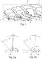
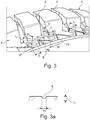
- Fig. 1 and Fig. 3 each show an oblique view of a circumferential section of a shoulder-side tread block row 1 of a tread of a pneumatic vehicle tire.
- the row of tread blocks 1 is composed in the circumferential direction of the pneumatic vehicle tire from a plurality of tread blocks 2 which are separated from one another by a transverse groove 3.
- the lateral edge of the ground contact area of the tread is indicated in each case by a dashed line.
- the ground contact area corresponds to the statically determined footprint according to ETRTO standards (load at 70% of the maximum load capacity with an internal pressure of 85% according to ETRTO standard).
- the shoulder-side row of tread blocks 1 is outside the ground contact area with a shoulder flank 4 which extends to a side wall of the tire (not shown), which is oriented essentially in the radial direction and, when viewed from the side of the tire, is circular - interrupted by transverse grooves 5, 5 'of the transverse grooves 3 - runs around the tire, Mistake.
- the rolling direction of the tire when driving forward is indicated by an arrow R in each case.
- the width of the transverse groove runs 5 ( Fig. 1 ) corresponds to the width of the transverse grooves 3 at the edge of the ground contact area, the width of the transverse groove outlets 5 '( Fig. 3 ) becomes larger towards their ends.
- flank grooves 6, 6' ( Fig. 1 ) and 6 "( Fig. 2 ), which extend at an obtuse angle ⁇ of 100 ° to 140 °, in particular up to 130 °, to the transverse groove runs 5, 5 ', the angle ⁇ being the angle between the center lines of the relevant grooves 5, 5', 6, 6 'and 6 ".
- the flank grooves 6, 6' and 6" thus run almost in the circumferential direction on the shoulder flank 4 and preferably in such a way that they are inclined towards the side wall and in this way to the circumferential direction at an angle ⁇ of preferably at least 5 ° run.
- the flank grooves 6, 6 ′ and 6 ′′ also have a length l 1 of 15.0 mm to 25.0 mm, which is determined starting from the inside corner of the kinks.
- the flank grooves 6, 6 'and 6 ′′ have a width b 1 on the outside of the shoulder flank 4, which continuously decreases between the kink to the respective transverse groove outlet 5, 5' and its end and over the majority of the course of the flank grooves 6, 6 'and 6 "is 1.5mm to 3.0mm.
- the flank grooves 6, 6 'and 6 " also have a depth t 2 ( Figures 2a, 2b ), which, starting from the depth t 1 of the transverse groove runs 5, 5 ', is reduced at the kink to its end and is at least 0.5 mm here.
- flank groove 6 ends at the shoulder flank 5 as a "closed” groove
- flank grooves 6 ′ and 6 ′′ are followed by additional groove sections 7a, 7b via further kinks
- the groove sections 7a essentially in run in the radial direction
- the groove sections 7b are oriented in the circumferential direction, but opposite to the flank grooves 6 ', 6 ".
- the groove sections 7a, 7b are shallow, their depth corresponds at the highest to the smallest depth of the flank grooves 6' and 6"
- their extension lengths l 2 ( from inside corner to inside corner) and l 3 (from inside corner to end) are 2.0 mm to 7.0 mm.
- each flank groove 6, 6 'and 6 has a cross-section that widens towards the outside of the shoulder flank 5, a groove bottom 6c and groove walls 6a, 6b running towards the outside of the shoulder flank 5, the groove wall 6b being the one that corresponds to the respective flank groove 6 , 6 'and 6 "are limited in the direction of the side wall, not shown.
- the groove wall 6a runs at an angle ⁇ to a perpendicular to the outside of the shoulder flank 5 of 20 ° to 60 °, in particular 30 ° to 50 °
- the groove wall 6b runs to a perpendicular to the outside of the shoulder flank at an angle ⁇ 'of 4 ° up to 15 °, in particular up to 10 °.
- the grooved wall 6b thus acts as a snow-compacting "edge", so that snow that collects and compacts in the flank grooves 6, 6 'and 6 "supports the effect of snow-snow friction well.
- the embodiment variant shown is provided exclusively on the shoulder flank 4 ′′.
- the additional groove sections 7b also each have an end 17 shaped like a V or arrowhead in plan view 6 ′′ each connected by an incision 8.
- the incisions 8 run straight, essentially parallel to or in continuation of the flank grooves 6 ′′, have a width b 2 on the outside of the shoulder flank 4 of 0.5 mm to 1.3 mm and an in particular constant depth t 3 of likewise 0.5 mm to 1.3 mm, as shown in Fig.
- the cross section of the incisions 8 is rounded.
- the incisions 8 provide additional grip edges to improve traction on deep snow.
Landscapes
- Engineering & Computer Science (AREA)
- Mechanical Engineering (AREA)
- Tires In General (AREA)
Description
- Die Erfindung betrifft einen Fahrzeugluftreifen mit Seitenwänden und mit einem profilierten, laufrichtungsgebunden gestalteten Laufstreifen, derart, dass der Fahrzeugluftreifen mit einer bestimmten Abrollrichtung bei Vorwärtsfahrt am Fahrzeug zu montieren ist,
wobei der Laufstreifen innerhalb seiner Bodenaufstandsfläche zumindest eine durch Querrillen in Profilblöcke gegliederte, schulterseitige Profilblockreihe aufweist, welche außerhalb der Bodenaufstandsfläche eine Schulterflanke besitzt, in welcher in Fortsetzung der Querrillen und in radialer Richtung verlaufend Querrillenausläufe verlaufen, deren Tiefe in Richtung zur Seitenwand abnimmt, wobei an die Querrillenausläufe über je eine Knickstelle Flankenrillen anschließen, welche sich bei am Fahrzeug montiertem Fahrzeugluftreifen gegen die Abrollrichtung bei Vorwärtsfahrt erstrecken. - Es ist üblich, Fahrzeugluftreifen mit Laufstreifen zu versehen, bei welchen schulterseitig verlaufende Querrillen über den seitlichen Rand der Bodenaufstandsfläche hinaus, in den sogenannten Off-Shoulder-Bereich, hinein verlaufen.
- Ein Fahrzeugluftreifen eingangs genannter Art ist aus der
EP 2 835 274 A1 bekannt. Dieser Fahrzeugluftreifen weist einen Laufstreifen mit einem laufrichtungsgebunden gestalteten Profil mit Querrillen auf, die sich über die Bodenaufstandsfläche hinaus bis zu einer Stützfläche erstrecken, wobei sich an der Stützfläche ein verlängerter Abschnitt jeder Querrille in Drehrichtung nach hinten biegt. Diese Ausgestaltung der Off-Shoulder-Bereiche soll die Traktionseigenschaften des Reifens in tiefem Schnee verbessern. - Ein weiterer Fahrzeugluftreifen mit Querrillenausläufen ist beispielsweise aus der
DE 10 2017 206 383 A1 bekannt. Die schulterseitigen Querrillen dieses Reifens laufen außerhalb der Bodenaufstandsfläche unter kontinuierlicher Verringerung ihrer Tiefe als flächige Vertiefungen aus, die, in Umfangsrichtung betrachtet, eine Breite aufweisen, welche um mindestens 40 % größer ist als die Breite der Querrillen innerhalb ihres Verlaufes in der Bodenaufstandsfläche. Durch die damit verbundene Vergrößerung des Querrillenquerschnittes im schulterseitigen Auslaufbereich der Querrillen kann bei Kurvenfahrt auf nasser Fahrbahn, das heißt unter Verlagerung der Bodenaufstandsfläche zur Kurvenaußenseite, Wasser besonders effektiv in den Off-Shoulder-Bereich abgeleitet werden. Weitere Fahrzeugluftreifen mit Laufstreifen, bei welchen schulterseitige Querrillen über die Bodenaufstandsfläche hinaus in die Off-Shoulder-Bereiche hinein verlaufen, sind aus derEP 3 124 290 A1 und derDE 10 2015 219 434 A1 bekannt. - Darüber hinaus ist es bekannt, in den Off-Shoulder-Bereichen des Laufstreifens Vertiefungen zur Erhöhung der Traktion beim Fahren auf weichem Untergrund, beispielsweise auf Schnee, Schneematsch oder matschig/erdigen oder unbefestigten Straßen, vorzusehen. Beim Fahren auf tieferem, losem Schnee kommt der Ausgestaltung der Off-Shoulder-Bereiche hinsichtlich des Schneegriffs und der Traktionseigenschaften des Reifens größere Bedeutung zu. Insbesondere auf losem Schnee sind die bislang üblichen und in die Off-Shoulder-Bereiche hinein verlaufenden Querrillenausläufe nicht in der Lage, einen nennenswerten Betrag zur Verbesserung der Traktion zu leisten.
- Der Erfindung liegt die Aufgabe zugrunde, bei einem Reifen der eingangs genannter Art die Griff- und Traktionseigenschaften auf mit losem, tiefem Schnee bedecktem Untergrund durch eine entsprechende Gestaltung der Off-Shoulder-Bereiche deutlich zu verbessern.
- Gelöst wird die gestellte Aufgabe erfindungsgemäß dadurch, dass die Flankenrillen unter einem stumpfen Winkel zu den Querrillenausläufen anschließen und zur Schulterflankenaußenseite verlaufende Rillenwände aufweisen, von welchen die eine vom Laufstreifen weiter entfernt befindliche Rillenwand unter einem kleineren Winkel zu einer Senkrechten auf die Schulterflankenaußenseite verläuft als die andere Rillenwand.
- Bei Vorwärtsfahrt auf mit tiefem Schnee bedecktem Untergrund sammelt sich Schnee in den Flankenrillen an, wobei die "flacher" verlaufenden Rillenwände das Ansammeln von Schnee in den Flankenrillen unterstützen und die "steiler" verlaufenden Rillenwände für ein Verdichten des Schnees sorgen. Der verdichtete Schnee unterstützt und begünstigt das Entstehen des Effektes der Schnee-Schnee -Reibung, welche gute Griff- und Traktionseigenschaften in den Off-Shoulder-Bereichen ermöglicht.
- Der erwünschte Effekt des Verdichtens von Schnee ist besonders ausgeprägt, wenn der Winkel der unter dem kleineren Winkel zu einer Senkrechten auf die Schulterflankenaußenseite verlaufenden Rillenwand 4° bis 15°, insbesondere bis zu 10°, beträgt und wenn ferner der Winkel der unter dem größeren Winkel zu einer Senkrechten auf die Schulterflankenaußenseite verlaufenden Rillenwand 20° bis 60°, insbesondere 30° bis 50°, beträgt. An der somit sehr "steilen" Rillenwand wird der über die relativ "flache" Rillenwand hineinrutschende lose Schnee besonders gut verdichtet.
- Vorzugsweise bei Vorwärtsfahrt sollen die Traktionseigenschaften auf tiefem losem Schnee besonders gut unterstützt werden. In diesem Zusammenhang ist es vorteilhaft, wenn der stumpfe Winkel zwischen den Querrillenausläufen und den Flankenrillen 100° bis 140°, insbesondere bis 130°, beträgt, wobei die Flankenrillen in Draufsicht auf die Schulterflanke vorzugsweise in Richtung zur Seitenwand geneigt sind.
- Der Effekt des Verdichtens des Schnees und des Auftretens der Schnee-Schnee-Reibung wird ferner dann begünstigt, wenn die Flankenrillen zwischen den Innenecken der Knickstellen und ihren Enden eine Länge von 15,0 mm bis 25,0 mm aufweisen und wenn ferner die Flankenrillen zumindest über den Großteil ihrer Erstreckung eine Breite von 1,5 mm bis 3,0 mm aufweisen. Bevorzugt ist dabei eine Ausführung, bei der die Breite der Flankenrillen zumindest über den Großteil ihrer Erstreckung von den Knickstellen bei den Querrillenausläufen ausgehend in Richtung zu den Enden der Flankenrillen geringer wird.
- Für den Effekt des Verdichtens von in die Flankenrillen eindringendem Schnee ist es weiters vorteilhaft, wenn die Flankenrillen eine Tiefe von 0,5 mm bis 2,5 mm aufweisen, wobei vorzugsweise diese Tiefe von den Knickstellen bei den Querrillenausläufen ausgehend in Richtung zu den Enden der Flankenrillen geringer wird.
- Bei einer bevorzugten Ausführung sind die Flankenrillen an ihren Enden geschlossen ausgeführt. Bei einer weiteren, ebenfalls bevorzugten Ausführung schließen an die Flankenrillen über Knickstellen zusätzlich Rillenabschnitte an, welche in radialer Richtung verlaufen. An diese zusätzlichen Rillenabschnitte kann gemäß einer weiteren bevorzugten Ausgestaltung über je eine Knickstelle jeweils ein weiterer Rillenabschnitt anschließen, welcher entgegengesetzt zu den Flankenrillen orientiert verläuft. Die zusätzlichen und die weiteren Rillenabschnitte weisen jeweils insbesondere eine Länge von 3,0 mm bis 7,0 mm auf. Durch diese relativ kurzen Rillenabschnitte werden in den Off-Shoulder-Bereichen oberflächlich zusätzliche Griffkanten zur Verfügung gestellt.
- Weitere, zusätzliche Griffkanten zur Verbesserung der Traktion auf tiefem, losem Schnee sind bei einer Ausführung vorhanden, bei welcher in Verlängerung der Flankenrillen jeweils ein Einschnitt mit einer Breite und mit einer Tiefe von 0,5 mm bis 1,3 mm verläuft. Vorzugsweise verbindet dieser Einschnitt das Ende eines entgegengesetzt zur Flankenrille verlaufenden Rillenabschnittes mit dem in Umfangsrichtung folgenden Außeneck der Knickstelle zwischen der Flankenrille und dem an diese anschließenden Rillenabschnitt.
- Weitere Merkmale, Vorteile und Einzelheiten der Erfindung werden nun anhand der Zeichnung, die schematisch Ausführungsbeispiele der Erfindung darstellt, näher beschrieben. Dabei zeigen
-
Fig. 1 eine Schrägansicht einer schulterseitigen Profilblockreihe eines Laufstreifens eines Fahrzeugluftreifens mit einer Ausführungsvariante der Erfindung, -
Fig. 2a einen Schnitt entlang der Linie IIa-IIa derFig. 1 , -
Fig. 3 in einer zuFig. 1 analogen Darstellung eine weitere Ausführungsvariante der Erfindung, -
Fig. 2b einen Schnitt entlang der Linie IIb-IIb derFig. 1 und derFig. 3 und -
Fig. 3a einen Schnitt entlang der Linie IIIa-IIIa derFig. 3 . - Gemäß der Erfindung ausgeführte Fahrzeugluftreifen sind für den Einsatz unter winterlichen Fahrbedingungen vorgesehene bzw. geeignete Fahrzeugluftreifen beliebigen Typs in Radialbauart, insbesondere Reifen für Personenkraftwagen, Vans, Light-Trucks, SUVs oder Pick-Ups. Erfindungsgemäß ausgeführte Fahrzeugluftreifen weisen ferner ein laufrichtungsgebunden gestaltetes Laufstreifenprofil auf, die Reifen sind daher gemäß ihrer vorgesehenen Abrollrichtung bei Vorwärtsfahrt am Fahrzeug zu montieren. Laufrichtungsgebunden gestaltete Laufstreifenprofile weisen beispielsweise "gepfeilt" verlaufende Querrillen oder Querrillen auf, die über einen Großteil der Laufstreifenbreite V-förmig verlaufend ausgebildet sind. Derartige Ausgestaltungen sind in einer Vielzahl von Ausführungsvarianten bekannt.
-
Fig. 1 undFig. 3 zeigen jeweils eine Schrägansicht eines Umfangsabschnittes einer schulterseitigen Profilblockreihe 1 eines Laufstreifens eines Fahrzeugluftreifens. Die Profilblockreihe 1 setzt sich in Umfangsrichtung des Fahrzeugluftreifens aus einer Vielzahl von Profilblöcken 2 zusammen, die von einander jeweils durch eine Querrille 3 getrennt sind. Der seitliche Rand der Bodenaufstandsfläche des Laufstreifens ist jeweils durch eine gestrichelte Linie angedeutet. Die Bodenaufstandsfläche entspricht beispielsweise bei einem Reifen für Personenkraftwagen dem statisch ermittelten Footprint gemäß ETRTO-Standards (Last bei 70 % der maximalen Tragfähigkeit bei einem Innendruck von 85 % nach ETRTO-Norm). Die schulterseitige Profilblockreihe 1 ist außerhalb der Bodenaufstandsfläche mit einer zu einer nicht gezeigten Seitenwand des Reifens verlaufenden Schulterflanke 4, welche im Wesentlichen in radialer Richtung orientiert ist und bei einer seitlichen Sicht auf den Reifen kreisringförmig - durch Querrillenausläufe 5, 5' der Querrillen 3 unterbrochen - den Reifen umläuft, versehen. Die Abrollrichtung des Reifens bei Vorwärtsfahrt ist jeweils durch einen Pfeil R gekennzeichnet. - Die Querrillenausläufe 5, 5' verlaufen in Fortsetzung der Querrillen 3 und weisen eine sich verringernde Tiefe auf, sodass am Ende der Querrillenausläufe 5, 5'die Tiefe t1 1,5 mm bis 2,5 mm beträgt. Die Breite der Querrillenausläufe 5 (
Fig. 1 ) entspricht der Breite der Querrillen 3 am Rand der Bodenaufstandsfläche, die Breite der Querrillenausläufe 5' (Fig. 3 ) wird in Richtung ihrer Enden größer. - An den Enden der Querrillenausläufe 5, 5' schließen über Knickstellen und gegen die Abrollrichtung bei Vorwärtsfahrt (Pfeile R) gerichtet Flankenrillen 6, 6' (
Fig. 1 ) und 6" (Fig. 2 ) an, welche unter einem stumpfen Winkel α von 100° bis 140°, insbesondere bis 130°, zu den Querrillenausläufen 5, 5' verlaufen, wobei der Winkel α der Winkel zwischen den Mittellinien der betreffenden Rillen 5, 5', 6, 6' und 6"ist. Die Flankenrillen 6, 6'und 6" verlaufen somit an der Schulterflanke 4 nahezu in Umfangsrichtung und bevorzugt derart, dass sie in Richtung zur Seitenwand geneigt sind und auf diese Weise zur Umfangsrichtung unter einem Winkel β von vorzugsweise mindesten 5° verlaufen. Die Flankenrillen 6, 6'und 6" weisen ferner eine Länge l1 von 15,0 mm bis 25,0 mm auf, die vom Inneneck der Knickstellen ausgehend ermittelt wird. - Die Flankenrillen 6, 6'und 6" weisen an der Außenseite der Schulterflanke 4 eine Breite b1 auf, die sich zwischen der Knickstelle zum jeweiligen Querrillenauslauf 5, 5' und ihrem Ende kontinuierlich verringert und über den Großteil des Verlaufes der Flankenrillen 6, 6'und 6" 1,5 mm bis 3,0 mm beträgt. Die Flankenrillen 6, 6'und 6" weisen ferner eine Tiefe t2 (
Fig. 2a, 2b ) auf, die sich ausgehend von der Tiefe t1 der Querrillenausläufe 5, 5' an der Knickstelle bis zu ihrem Ende verringert und hier mindestens 0,5 mm beträgt. - Die Flankenrille 6 endet an der Schulterflanke 5 als "geschlossene" Rille, hingegen schließen an die Flankenrillen 6'und 6" über weitere Knickstellen zusätzliche Rillenabschnitte 7a, 7b an, wobei die Rillenabschnitte 7a im Wesentlichen in radialer Richtung verlaufen und die Rillenabschnitte 7b in Umfangsrichtung, jedoch entgegengesetzt zu den Flankenrillen 6', 6" orientiert sind. Die Rillenabschnitte 7a, 7b sind seicht, ihre Tiefe entspricht höchsten der geringsten Tiefe der Flankenrillen 6'und 6" ihre Erstreckungslängen l2 (von Inneneck zu Inneneck) und l3 (vom Inneneck zum Ende) betragen 2,0 mm bis 7,0 mm.
- Wie die Schnittdarstellungen in
Fig. 2a und 2b zeigen weist jede Flankenrille 6, 6'und 6" einen sich zur Außenseite der Schulterflanke 5 verbreiternden Querschnitt, einen Rillenboden 6c und zur Außenseite der Schulterflanke 5 verlaufende Rillenwände 6a, 6b auf, wobei die Rillenwand 6b jeweils jene ist, welche die jeweilige Flankenrille 6, 6'und 6" in Richtung zur nicht dargestellten Seitenwand begrenzt. Die Rillenwand 6a verläuft unter einem Winkel γ zu einer Senkrechten auf die Außenseite der Schulterflanke 5 von 20° bis 60°, insbesondere 30° bis 50, die Rillenwand 6b verläuft zu einer Senkrechten auf die Außenseite der Schulterflanke unter einem Winkel γ' von 4° bis 15°, insbesondere bis 10°. Bei Vorwärtsfahrt in tieferem Schnee wirkt somit die Rillenwand 6b als Schnee verdichtende "Kante", sodass in den Flankenrillen 6, 6'und 6" sich ansammelnder und verdichtender Schnee den Effekt der Schnee-Schnee-Reibung gut unterstützt. - Bei der in
Fig. 1 gezeigten Ausführung wechselt in Umfangsrichtung jeweils eine Flankenrille 6 mit einer Flankenrille 6' ab. - Bei der in
Fig. 3 gezeigten Ausführungsvariante sind an der Schulterflanke 4 ausschließlich Flankenrillen 6" vorgesehen. Die zusätzlichen Rillenabschnitte 7b weisen ferner jeweils ein in Draufsicht V- oder pfeilspitzenförmiges Ende 17 auf. Die Enden 17 sind mit den in Umfangsrichtung folgenden Außenecken der Knickstellen zwischen den Rillenabschnitten 7a und den Flankenrillen 6" jeweils durch einen Einschnitt 8 verbunden. Die Einschnitte 8 verlaufen gerade, im Wesentlichen parallel zu den bzw. in Fortsetzung der Flankenrillen 6", weisen eine Breite b2 an der Außenseite der Schulterflanke 4 von 0,5 mm bis 1,3 mm und eine insbesondere konstante Tiefe t3 von ebenfalls 0,5 mm bis 1,3 mm auf, wie in Fig. - 3a gezeigt. Der Querschnitt der Einschnitte 8 ist gerundet. Die Einschnitte 8 stellen zusätzliche Griffkanten zur Verbesserung der Traktion auf tiefem Schnee zur Verfügung.
-
- 1
- Profilblockreihe
- 2
- Profilblock
- 3
- Querrille
- 4
- Schulterflanke
- 5, 5'
- Querrillenauslauf
- 6, 6', 6"
- Flankenrille
- 6a, 6b
- Rillenwand
- 6c
- Rillenboden
- 7a, 7b
- Rillenabschnitt
- 8
- Einschnitt
- 17
- Ende
- b1, b2
- Breite
- t1, t2, t3
- Tiefe
- l1, l2, l3
- Länge
- α, β, γ, γ'
- Winkel
Claims (14)
- Fahrzeugluftreifen mit Seitenwänden und mit einem profilierten, laufrichtungsgebunden gestalteten Laufstreifen, derart, dass der Fahrzeugluftreifen mit einer bestimmten Abrollrichtung (R) bei Vorwärtsfahrt am Fahrzeug zu montieren ist,wobei der Laufstreifen innerhalb seiner Bodenaufstandsfläche zumindest eine durch Querrillen (3) in Profilblöcke (2) gegliederte, schulterseitige Profilblockreihe (1) aufweist, welche außerhalb der Bodenaufstandsfläche eine Schulterflanke (4) besitzt, in welcher in Fortsetzung der Querrillen (3) und in radialer Richtung verlaufend Querrillenausläufe (5, 5') verlaufen, deren Tiefe in Richtung zur Seitenwand abnimmt, wobei an die Querrillenausläufe (5, 5') über je eine Knickstelle Flankenrillen (6, 6', 6") anschließen, welche sich bei am Fahrzeug montiertem Fahrzeugluftreifen gegen die Abrollrichtung (R) bei Vorwärtsfahrt erstrecken,dadurch gekennzeichnet,dass die Flankenrillen (6, 6', 6") unter einem stumpfen Winkel (α) zu den Querrillenausläufen (5, 5') anschließen und zur Schulterflankenaußenseite verlaufende Rillenwände (6a, 6b) aufweisen, von welchen die eine, vom Laufstreifen weiter entfernt befindliche Rillenwand (6b) unter einem kleineren Winkel (γ') zu einer Senkrechten auf die Schulterflankenaußenseite verläuft als die andere Rillenwand (6a).
- Fahrzeugluftreifen nach Anspruch 1, dadurch gekennzeichnet, dass der Winkel (γ') der unter dem kleineren Winkel zu einer Senkrechten auf die Schulterflankenaußenseite verlaufenden Rillenwand (6b) 4° bis 15°, insbesondere bis zu 10°, beträgt.
- Fahrzeugluftreifen nach Anspruch 1 oder 2, dadurch gekennzeichnet, dass der Winkel (γ) der unter dem größeren Winkel zu einer Senkrechten auf die Schulterflankenaußenseite verlaufenden Rillenwand (6a) 20° bis 60°, insbesondere 30° bis 50°, beträgt.
- Fahrzeugluftreifen nach einem der Ansprüche 1 bis 3, dadurch gekennzeichnet, dass der stumpfe Winkel (α) zwischen den Querrillenausläufen (5, 5') und den Flankenrillen (6, 6', 6") 100° bis 140°, insbesondere bis 130°, beträgt, wobei die Flankenrillen (6, 6', 6") in Draufsicht auf die Schulterflanke (4) vorzugsweise in Richtung zur Seitenwand geneigt sind.
- Fahrzeugluftreifen nach einem der Ansprüche 1 bis 4, dadurch gekennzeichnet, dass die Flankenrillen (6, 6', 6") zwischen den Innenecken der Knickstellen und ihren Enden eine Länge (l1) von 15,0 mm bis 25, 0 mm aufweisen.
- Fahrzeugluftreifen nach einem der Ansprüche 1 bis 5, dadurch gekennzeichnet, dass die Flankenrillen (6, 6', 6") zumindest über den Großteil ihrer Erstreckung eine Breite (b1) von 1,5 mm bis 3,0 mm aufweisen.
- Fahrzeugluftreifen nach einem der Ansprüche 1 bis 6, dadurch gekennzeichnet, dass die Flankenrillen (6, 6', 6") zumindest über den Großteil ihrer Erstreckung eine Breite (b1) aufweisen, die von den Knickstellen zu den Querrillenausläufen (5, 5') ausgehend in Richtung zu ihren Enden geringer wird.
- Fahrzeugluftreifen nach einem der Ansprüche 1 bis 7, dadurch gekennzeichnet, dass die Flankenrillen (6, 6', 6") eine Tiefe (t2) von 0,5 mm bis 2,5 mm aufweisen.
- Fahrzeugluftreifen nach einem der Ansprüche 1 bis 8, dadurch gekennzeichnet, dass die Flankenrillen (6, 6', 6") eine Tiefe (t2) aufweisen, die von der Knickstellen zu den Querrillenausläufen (5, 5') ausgehend in Richtung zu ihren Enden geringer wird.
- Fahrzeugluftreifen nach einem der Ansprüche 1 bis 9, dadurch gekennzeichnet, dass an die Flankenrillen (6', 6") über Knickstellen zusätzlich Rillenabschnitte (7a) anschließen, welche in radialer Richtung verlaufen.
- Fahrzeugluftreifen nach Anspruch 10, dadurch gekennzeichnet, dass an die zusätzlichen Rillenabschnitte (7a) über je eine Knickstelle ein weiterer Rillenabschnitt (7b) anschließt, welcher entgegengesetzt zu den Flankenrillen (6', 6") verläuft.
- Fahrzeugluftreifen nach Anspruch 10 oder 11, dadurch gekennzeichnet, dass die zusätzlichen Rillenabschnitte (7a) und die weiteren Rillenabschnitte (7b) jeweils eine Länge (l2, l3) von 3,0 mm bis 7,0 mm aufweisen.
- Fahrzeugluftreifen nach einem der Ansprüche 1 bis 12, dadurch gekennzeichnet, dass in Verlängerung der Flankenrillen (6") jeweils ein Einschnitt (8) mit einer Breite (b3) und einer Tiefe (t2) von 0,5 mm bis 1,3 mm verläuft.
- Fahrzeugluftreifen nach Anspruch 13, dadurch gekennzeichnet, dass der Einschnitt (8) das Ende eines entgegengesetzt zur Flankenrille (6") verlaufenden Rillenabschnittes (7b) mit dem in Umfangsrichtung folgenden Außeneck der Knickstelle zwischen der Flankenrille (6") und dem an diese anschließenden Rillenabschnitt (7a) verbindet.
Applications Claiming Priority (1)
| Application Number | Priority Date | Filing Date | Title |
|---|---|---|---|
| DE102019200901.8A DE102019200901A1 (de) | 2019-01-24 | 2019-01-24 | Fahrzeugluftreifen |
Publications (2)
| Publication Number | Publication Date |
|---|---|
| EP3686034A1 EP3686034A1 (de) | 2020-07-29 |
| EP3686034B1 true EP3686034B1 (de) | 2021-10-20 |
Family
ID=68470316
Family Applications (1)
| Application Number | Title | Priority Date | Filing Date |
|---|---|---|---|
| EP19207349.2A Active EP3686034B1 (de) | 2019-01-24 | 2019-11-06 | Fahrzeugluftreifen |
Country Status (2)
| Country | Link |
|---|---|
| EP (1) | EP3686034B1 (de) |
| DE (1) | DE102019200901A1 (de) |
Families Citing this family (1)
| Publication number | Priority date | Publication date | Assignee | Title |
|---|---|---|---|---|
| JP2023010598A (ja) * | 2021-07-09 | 2023-01-20 | 横浜ゴム株式会社 | タイヤ |
Family Cites Families (11)
| Publication number | Priority date | Publication date | Assignee | Title |
|---|---|---|---|---|
| JP3676534B2 (ja) * | 1997-04-10 | 2005-07-27 | 株式会社ブリヂストン | 空気入りタイヤ |
| JP3930391B2 (ja) * | 2002-07-29 | 2007-06-13 | 住友ゴム工業株式会社 | 空気入りタイヤ |
| JP4829994B2 (ja) * | 2009-04-06 | 2011-12-07 | 住友ゴム工業株式会社 | 空気入りタイヤ |
| DE102010060255B4 (de) * | 2010-10-29 | 2020-09-24 | Continental Reifen Deutschland Gmbh | Laufstreifenprofil eines Fahrzeugluftreifens |
| JP5731852B2 (ja) * | 2011-02-24 | 2015-06-10 | 株式会社ブリヂストン | タイヤ |
| JP5519721B2 (ja) * | 2012-04-05 | 2014-06-11 | 株式会社ブリヂストン | 空気入りタイヤ |
| JP5945258B2 (ja) * | 2013-09-11 | 2016-07-05 | 住友ゴム工業株式会社 | 空気入りタイヤ |
| JP6400423B2 (ja) | 2014-10-09 | 2018-10-03 | 東洋ゴム工業株式会社 | 空気入りタイヤ |
| DE102015214483A1 (de) | 2015-07-30 | 2017-02-02 | Continental Reifen Deutschland Gmbh | Fahrzeugluftreifen |
| DE102016218981A1 (de) * | 2016-09-30 | 2018-04-05 | Continental Reifen Deutschland Gmbh | Fahrzeugluftreifen |
| DE102017206383A1 (de) | 2017-04-13 | 2018-10-18 | Continental Reifen Deutschland Gmbh | Fahrzeugluftreifen |
-
2019
- 2019-01-24 DE DE102019200901.8A patent/DE102019200901A1/de not_active Withdrawn
- 2019-11-06 EP EP19207349.2A patent/EP3686034B1/de active Active
Also Published As
| Publication number | Publication date |
|---|---|
| EP3686034A1 (de) | 2020-07-29 |
| DE102019200901A1 (de) | 2020-07-30 |
Similar Documents
| Publication | Publication Date | Title |
|---|---|---|
| EP3589501B1 (de) | Fahrzeugluftreifen | |
| EP3589500B1 (de) | Fahrzeugluftreifen | |
| EP3388256B1 (de) | Fahrzeugluftreifen | |
| EP3256334B1 (de) | Fahrzeugluftreifen | |
| EP3300926B1 (de) | Fahrzeugluftreifen | |
| DE102019213044A1 (de) | Fahrzeugluftreifen | |
| EP3009275B1 (de) | Fahrzeugluftreifen | |
| WO2019115036A1 (de) | Nutzfahrzeugreifen | |
| EP3421264A1 (de) | Fahrzeugluftreifen | |
| EP4577416A1 (de) | Fahrzeugluftreifen | |
| EP3441241B1 (de) | Fahrzeugluftreifen | |
| EP4058304B1 (de) | Fahrzeugluftreifen | |
| EP0773117A1 (de) | Drehrichtungsungebundenes Laufstreifenprofil eines Fahrzeugreifens mit Blockprofilstruktur | |
| EP3686034B1 (de) | Fahrzeugluftreifen | |
| EP2138329B1 (de) | Laufflächenprofil für einen Fahrzeugluftreifen | |
| DE102008029659A1 (de) | Fahrzeugluftreifen | |
| EP2594416B1 (de) | Laufstreifen-Schulterbereich | |
| EP3300925B1 (de) | Fahrzeugluftreifen | |
| EP4244079B1 (de) | Fahrzeugluftreifen | |
| EP3888949B1 (de) | Fahrzeugluftreifen | |
| EP3663105B1 (de) | Fahrzeugreifen | |
| EP3418076B1 (de) | Fahrzeugluftreifen | |
| DE102008029658A1 (de) | Fahrzeugluftreifen | |
| EP3831619A1 (de) | Fahrzeugluftreifen | |
| EP4140776B1 (de) | Fahrzeugluftreifen |
Legal Events
| Date | Code | Title | Description |
|---|---|---|---|
| PUAI | Public reference made under article 153(3) epc to a published international application that has entered the european phase |
Free format text: ORIGINAL CODE: 0009012 |
|
| STAA | Information on the status of an ep patent application or granted ep patent |
Free format text: STATUS: THE APPLICATION HAS BEEN PUBLISHED |
|
| AK | Designated contracting states |
Kind code of ref document: A1 Designated state(s): AL AT BE BG CH CY CZ DE DK EE ES FI FR GB GR HR HU IE IS IT LI LT LU LV MC MK MT NL NO PL PT RO RS SE SI SK SM TR |
|
| AX | Request for extension of the european patent |
Extension state: BA ME |
|
| RAP1 | Party data changed (applicant data changed or rights of an application transferred) |
Owner name: CONTINENTAL REIFEN DEUTSCHLAND GMBH |
|
| STAA | Information on the status of an ep patent application or granted ep patent |
Free format text: STATUS: REQUEST FOR EXAMINATION WAS MADE |
|
| 17P | Request for examination filed |
Effective date: 20210129 |
|
| RBV | Designated contracting states (corrected) |
Designated state(s): AL AT BE BG CH CY CZ DE DK EE ES FI FR GB GR HR HU IE IS IT LI LT LU LV MC MK MT NL NO PL PT RO RS SE SI SK SM TR |
|
| GRAP | Despatch of communication of intention to grant a patent |
Free format text: ORIGINAL CODE: EPIDOSNIGR1 |
|
| STAA | Information on the status of an ep patent application or granted ep patent |
Free format text: STATUS: GRANT OF PATENT IS INTENDED |
|
| INTG | Intention to grant announced |
Effective date: 20210521 |
|
| GRAS | Grant fee paid |
Free format text: ORIGINAL CODE: EPIDOSNIGR3 |
|
| GRAA | (expected) grant |
Free format text: ORIGINAL CODE: 0009210 |
|
| STAA | Information on the status of an ep patent application or granted ep patent |
Free format text: STATUS: THE PATENT HAS BEEN GRANTED |
|
| AK | Designated contracting states |
Kind code of ref document: B1 Designated state(s): AL AT BE BG CH CY CZ DE DK EE ES FI FR GB GR HR HU IE IS IT LI LT LU LV MC MK MT NL NO PL PT RO RS SE SI SK SM TR |
|
| REG | Reference to a national code |
Ref country code: GB Ref legal event code: FG4D Free format text: NOT ENGLISH |
|
| REG | Reference to a national code |
Ref country code: CH Ref legal event code: EP |
|
| REG | Reference to a national code |
Ref country code: DE Ref legal event code: R096 Ref document number: 502019002545 Country of ref document: DE |
|
| REG | Reference to a national code |
Ref country code: IE Ref legal event code: FG4D Free format text: LANGUAGE OF EP DOCUMENT: GERMAN |
|
| REG | Reference to a national code |
Ref country code: AT Ref legal event code: REF Ref document number: 1439643 Country of ref document: AT Kind code of ref document: T Effective date: 20211115 |
|
| REG | Reference to a national code |
Ref country code: SE Ref legal event code: TRGR |
|
| REG | Reference to a national code |
Ref country code: LT Ref legal event code: MG9D |
|
| REG | Reference to a national code |
Ref country code: NL Ref legal event code: MP Effective date: 20211020 |
|
| PG25 | Lapsed in a contracting state [announced via postgrant information from national office to epo] |
Ref country code: RS Free format text: LAPSE BECAUSE OF FAILURE TO SUBMIT A TRANSLATION OF THE DESCRIPTION OR TO PAY THE FEE WITHIN THE PRESCRIBED TIME-LIMIT Effective date: 20211020 Ref country code: LT Free format text: LAPSE BECAUSE OF FAILURE TO SUBMIT A TRANSLATION OF THE DESCRIPTION OR TO PAY THE FEE WITHIN THE PRESCRIBED TIME-LIMIT Effective date: 20211020 Ref country code: FI Free format text: LAPSE BECAUSE OF FAILURE TO SUBMIT A TRANSLATION OF THE DESCRIPTION OR TO PAY THE FEE WITHIN THE PRESCRIBED TIME-LIMIT Effective date: 20211020 Ref country code: BG Free format text: LAPSE BECAUSE OF FAILURE TO SUBMIT A TRANSLATION OF THE DESCRIPTION OR TO PAY THE FEE WITHIN THE PRESCRIBED TIME-LIMIT Effective date: 20220120 |
|
| PG25 | Lapsed in a contracting state [announced via postgrant information from national office to epo] |
Ref country code: IS Free format text: LAPSE BECAUSE OF FAILURE TO SUBMIT A TRANSLATION OF THE DESCRIPTION OR TO PAY THE FEE WITHIN THE PRESCRIBED TIME-LIMIT Effective date: 20220220 Ref country code: PT Free format text: LAPSE BECAUSE OF FAILURE TO SUBMIT A TRANSLATION OF THE DESCRIPTION OR TO PAY THE FEE WITHIN THE PRESCRIBED TIME-LIMIT Effective date: 20220221 Ref country code: PL Free format text: LAPSE BECAUSE OF FAILURE TO SUBMIT A TRANSLATION OF THE DESCRIPTION OR TO PAY THE FEE WITHIN THE PRESCRIBED TIME-LIMIT Effective date: 20211020 Ref country code: NO Free format text: LAPSE BECAUSE OF FAILURE TO SUBMIT A TRANSLATION OF THE DESCRIPTION OR TO PAY THE FEE WITHIN THE PRESCRIBED TIME-LIMIT Effective date: 20220120 Ref country code: NL Free format text: LAPSE BECAUSE OF FAILURE TO SUBMIT A TRANSLATION OF THE DESCRIPTION OR TO PAY THE FEE WITHIN THE PRESCRIBED TIME-LIMIT Effective date: 20211020 Ref country code: LV Free format text: LAPSE BECAUSE OF FAILURE TO SUBMIT A TRANSLATION OF THE DESCRIPTION OR TO PAY THE FEE WITHIN THE PRESCRIBED TIME-LIMIT Effective date: 20211020 Ref country code: HR Free format text: LAPSE BECAUSE OF FAILURE TO SUBMIT A TRANSLATION OF THE DESCRIPTION OR TO PAY THE FEE WITHIN THE PRESCRIBED TIME-LIMIT Effective date: 20211020 Ref country code: GR Free format text: LAPSE BECAUSE OF FAILURE TO SUBMIT A TRANSLATION OF THE DESCRIPTION OR TO PAY THE FEE WITHIN THE PRESCRIBED TIME-LIMIT Effective date: 20220121 Ref country code: ES Free format text: LAPSE BECAUSE OF FAILURE TO SUBMIT A TRANSLATION OF THE DESCRIPTION OR TO PAY THE FEE WITHIN THE PRESCRIBED TIME-LIMIT Effective date: 20211020 |
|
| REG | Reference to a national code |
Ref country code: DE Ref legal event code: R097 Ref document number: 502019002545 Country of ref document: DE |
|
| PG25 | Lapsed in a contracting state [announced via postgrant information from national office to epo] |
Ref country code: SM Free format text: LAPSE BECAUSE OF FAILURE TO SUBMIT A TRANSLATION OF THE DESCRIPTION OR TO PAY THE FEE WITHIN THE PRESCRIBED TIME-LIMIT Effective date: 20211020 Ref country code: SK Free format text: LAPSE BECAUSE OF FAILURE TO SUBMIT A TRANSLATION OF THE DESCRIPTION OR TO PAY THE FEE WITHIN THE PRESCRIBED TIME-LIMIT Effective date: 20211020 Ref country code: RO Free format text: LAPSE BECAUSE OF FAILURE TO SUBMIT A TRANSLATION OF THE DESCRIPTION OR TO PAY THE FEE WITHIN THE PRESCRIBED TIME-LIMIT Effective date: 20211020 Ref country code: MC Free format text: LAPSE BECAUSE OF FAILURE TO SUBMIT A TRANSLATION OF THE DESCRIPTION OR TO PAY THE FEE WITHIN THE PRESCRIBED TIME-LIMIT Effective date: 20211020 Ref country code: LU Free format text: LAPSE BECAUSE OF NON-PAYMENT OF DUE FEES Effective date: 20211106 Ref country code: EE Free format text: LAPSE BECAUSE OF FAILURE TO SUBMIT A TRANSLATION OF THE DESCRIPTION OR TO PAY THE FEE WITHIN THE PRESCRIBED TIME-LIMIT Effective date: 20211020 Ref country code: DK Free format text: LAPSE BECAUSE OF FAILURE TO SUBMIT A TRANSLATION OF THE DESCRIPTION OR TO PAY THE FEE WITHIN THE PRESCRIBED TIME-LIMIT Effective date: 20211020 Ref country code: CZ Free format text: LAPSE BECAUSE OF FAILURE TO SUBMIT A TRANSLATION OF THE DESCRIPTION OR TO PAY THE FEE WITHIN THE PRESCRIBED TIME-LIMIT Effective date: 20211020 Ref country code: BE Free format text: LAPSE BECAUSE OF NON-PAYMENT OF DUE FEES Effective date: 20211130 |
|
| REG | Reference to a national code |
Ref country code: BE Ref legal event code: MM Effective date: 20211130 |
|
| PLBE | No opposition filed within time limit |
Free format text: ORIGINAL CODE: 0009261 |
|
| STAA | Information on the status of an ep patent application or granted ep patent |
Free format text: STATUS: NO OPPOSITION FILED WITHIN TIME LIMIT |
|
| 26N | No opposition filed |
Effective date: 20220721 |
|
| PG25 | Lapsed in a contracting state [announced via postgrant information from national office to epo] |
Ref country code: IE Free format text: LAPSE BECAUSE OF NON-PAYMENT OF DUE FEES Effective date: 20211106 Ref country code: AL Free format text: LAPSE BECAUSE OF FAILURE TO SUBMIT A TRANSLATION OF THE DESCRIPTION OR TO PAY THE FEE WITHIN THE PRESCRIBED TIME-LIMIT Effective date: 20211020 |
|
| PG25 | Lapsed in a contracting state [announced via postgrant information from national office to epo] |
Ref country code: SI Free format text: LAPSE BECAUSE OF FAILURE TO SUBMIT A TRANSLATION OF THE DESCRIPTION OR TO PAY THE FEE WITHIN THE PRESCRIBED TIME-LIMIT Effective date: 20211020 Ref country code: FR Free format text: LAPSE BECAUSE OF NON-PAYMENT OF DUE FEES Effective date: 20211220 |
|
| PG25 | Lapsed in a contracting state [announced via postgrant information from national office to epo] |
Ref country code: IT Free format text: LAPSE BECAUSE OF FAILURE TO SUBMIT A TRANSLATION OF THE DESCRIPTION OR TO PAY THE FEE WITHIN THE PRESCRIBED TIME-LIMIT Effective date: 20211020 |
|
| PG25 | Lapsed in a contracting state [announced via postgrant information from national office to epo] |
Ref country code: CY Free format text: LAPSE BECAUSE OF FAILURE TO SUBMIT A TRANSLATION OF THE DESCRIPTION OR TO PAY THE FEE WITHIN THE PRESCRIBED TIME-LIMIT Effective date: 20211020 |
|
| REG | Reference to a national code |
Ref country code: CH Ref legal event code: PL |
|
| PG25 | Lapsed in a contracting state [announced via postgrant information from national office to epo] |
Ref country code: LI Free format text: LAPSE BECAUSE OF NON-PAYMENT OF DUE FEES Effective date: 20221130 Ref country code: HU Free format text: LAPSE BECAUSE OF FAILURE TO SUBMIT A TRANSLATION OF THE DESCRIPTION OR TO PAY THE FEE WITHIN THE PRESCRIBED TIME-LIMIT; INVALID AB INITIO Effective date: 20191106 Ref country code: CH Free format text: LAPSE BECAUSE OF NON-PAYMENT OF DUE FEES Effective date: 20221130 |
|
| REG | Reference to a national code |
Ref country code: DE Ref legal event code: R081 Ref document number: 502019002545 Country of ref document: DE Owner name: CONTINENTAL REIFEN DEUTSCHLAND GMBH, DE Free format text: FORMER OWNER: CONTINENTAL REIFEN DEUTSCHLAND GMBH, 30165 HANNOVER, DE |
|
| PG25 | Lapsed in a contracting state [announced via postgrant information from national office to epo] |
Ref country code: MK Free format text: LAPSE BECAUSE OF FAILURE TO SUBMIT A TRANSLATION OF THE DESCRIPTION OR TO PAY THE FEE WITHIN THE PRESCRIBED TIME-LIMIT Effective date: 20211020 |
|
| GBPC | Gb: european patent ceased through non-payment of renewal fee |
Effective date: 20231106 |
|
| PG25 | Lapsed in a contracting state [announced via postgrant information from national office to epo] |
Ref country code: MT Free format text: LAPSE BECAUSE OF FAILURE TO SUBMIT A TRANSLATION OF THE DESCRIPTION OR TO PAY THE FEE WITHIN THE PRESCRIBED TIME-LIMIT Effective date: 20211020 |
|
| PG25 | Lapsed in a contracting state [announced via postgrant information from national office to epo] |
Ref country code: GB Free format text: LAPSE BECAUSE OF NON-PAYMENT OF DUE FEES Effective date: 20231106 |
|
| PG25 | Lapsed in a contracting state [announced via postgrant information from national office to epo] |
Ref country code: GB Free format text: LAPSE BECAUSE OF NON-PAYMENT OF DUE FEES Effective date: 20231106 |
|
| PG25 | Lapsed in a contracting state [announced via postgrant information from national office to epo] |
Ref country code: TR Free format text: LAPSE BECAUSE OF FAILURE TO SUBMIT A TRANSLATION OF THE DESCRIPTION OR TO PAY THE FEE WITHIN THE PRESCRIBED TIME-LIMIT Effective date: 20211020 |
|
| PGFP | Annual fee paid to national office [announced via postgrant information from national office to epo] |
Ref country code: DE Payment date: 20251130 Year of fee payment: 7 |
|
| PG25 | Lapsed in a contracting state [announced via postgrant information from national office to epo] |
Ref country code: AT Free format text: LAPSE BECAUSE OF NON-PAYMENT OF DUE FEES Effective date: 20241106 |
|
| REG | Reference to a national code |
Ref country code: AT Ref legal event code: MM01 Ref document number: 1439643 Country of ref document: AT Kind code of ref document: T Effective date: 20241106 |
|
| PGFP | Annual fee paid to national office [announced via postgrant information from national office to epo] |
Ref country code: SE Payment date: 20251119 Year of fee payment: 7 |
|
| PGFP | Annual fee paid to national office [announced via postgrant information from national office to epo] |
Ref country code: AT Payment date: 20260410 Year of fee payment: 5 |