EP3686034B1 - Pneumatiques de véhicule - Google Patents
Pneumatiques de véhicule Download PDFInfo
- Publication number
- EP3686034B1 EP3686034B1 EP19207349.2A EP19207349A EP3686034B1 EP 3686034 B1 EP3686034 B1 EP 3686034B1 EP 19207349 A EP19207349 A EP 19207349A EP 3686034 B1 EP3686034 B1 EP 3686034B1
- Authority
- EP
- European Patent Office
- Prior art keywords
- flank
- groove
- grooves
- pneumatic vehicle
- vehicle tyre
- Prior art date
- Legal status (The legal status is an assumption and is not a legal conclusion. Google has not performed a legal analysis and makes no representation as to the accuracy of the status listed.)
- Active
Links
- 238000005096 rolling process Methods 0.000 claims description 6
- 230000007423 decrease Effects 0.000 claims description 3
- 230000000694 effects Effects 0.000 description 5
- 238000009825 accumulation Methods 0.000 description 1
- 238000005452 bending Methods 0.000 description 1
- 230000003247 decreasing effect Effects 0.000 description 1
- 230000000149 penetrating effect Effects 0.000 description 1
- XLYOFNOQVPJJNP-UHFFFAOYSA-N water Substances O XLYOFNOQVPJJNP-UHFFFAOYSA-N 0.000 description 1
Images
Classifications
-
- B—PERFORMING OPERATIONS; TRANSPORTING
- B60—VEHICLES IN GENERAL
- B60C—VEHICLE TYRES; TYRE INFLATION; TYRE CHANGING; CONNECTING VALVES TO INFLATABLE ELASTIC BODIES IN GENERAL; DEVICES OR ARRANGEMENTS RELATED TO TYRES
- B60C11/00—Tyre tread bands; Tread patterns; Anti-skid inserts
- B60C11/03—Tread patterns
- B60C11/0311—Patterns comprising tread lugs arranged parallel or oblique to the axis of rotation
- B60C11/0316—Patterns comprising tread lugs arranged parallel or oblique to the axis of rotation further characterised by the groove cross-section
-
- B—PERFORMING OPERATIONS; TRANSPORTING
- B60—VEHICLES IN GENERAL
- B60C—VEHICLE TYRES; TYRE INFLATION; TYRE CHANGING; CONNECTING VALVES TO INFLATABLE ELASTIC BODIES IN GENERAL; DEVICES OR ARRANGEMENTS RELATED TO TYRES
- B60C11/00—Tyre tread bands; Tread patterns; Anti-skid inserts
- B60C11/01—Shape of the shoulders between tread and sidewall, e.g. rounded, stepped or cantilevered
-
- B—PERFORMING OPERATIONS; TRANSPORTING
- B60—VEHICLES IN GENERAL
- B60C—VEHICLE TYRES; TYRE INFLATION; TYRE CHANGING; CONNECTING VALVES TO INFLATABLE ELASTIC BODIES IN GENERAL; DEVICES OR ARRANGEMENTS RELATED TO TYRES
- B60C11/00—Tyre tread bands; Tread patterns; Anti-skid inserts
- B60C11/03—Tread patterns
- B60C11/13—Tread patterns characterised by the groove cross-section, e.g. for buttressing or preventing stone-trapping
- B60C11/1307—Tread patterns characterised by the groove cross-section, e.g. for buttressing or preventing stone-trapping with special features of the groove walls
- B60C11/1323—Tread patterns characterised by the groove cross-section, e.g. for buttressing or preventing stone-trapping with special features of the groove walls asymmetric
-
- B—PERFORMING OPERATIONS; TRANSPORTING
- B60—VEHICLES IN GENERAL
- B60C—VEHICLE TYRES; TYRE INFLATION; TYRE CHANGING; CONNECTING VALVES TO INFLATABLE ELASTIC BODIES IN GENERAL; DEVICES OR ARRANGEMENTS RELATED TO TYRES
- B60C11/00—Tyre tread bands; Tread patterns; Anti-skid inserts
- B60C11/03—Tread patterns
- B60C11/0306—Patterns comprising block rows or discontinuous ribs
-
- B—PERFORMING OPERATIONS; TRANSPORTING
- B60—VEHICLES IN GENERAL
- B60C—VEHICLE TYRES; TYRE INFLATION; TYRE CHANGING; CONNECTING VALVES TO INFLATABLE ELASTIC BODIES IN GENERAL; DEVICES OR ARRANGEMENTS RELATED TO TYRES
- B60C11/00—Tyre tread bands; Tread patterns; Anti-skid inserts
- B60C11/03—Tread patterns
- B60C11/0311—Patterns comprising tread lugs arranged parallel or oblique to the axis of rotation
- B60C2011/0313—Patterns comprising tread lugs arranged parallel or oblique to the axis of rotation directional type
-
- B—PERFORMING OPERATIONS; TRANSPORTING
- B60—VEHICLES IN GENERAL
- B60C—VEHICLE TYRES; TYRE INFLATION; TYRE CHANGING; CONNECTING VALVES TO INFLATABLE ELASTIC BODIES IN GENERAL; DEVICES OR ARRANGEMENTS RELATED TO TYRES
- B60C11/00—Tyre tread bands; Tread patterns; Anti-skid inserts
- B60C11/03—Tread patterns
- B60C2011/0337—Tread patterns characterised by particular design features of the pattern
- B60C2011/0339—Grooves
- B60C2011/0358—Lateral grooves, i.e. having an angle of 45 to 90 degees to the equatorial plane
- B60C2011/0365—Lateral grooves, i.e. having an angle of 45 to 90 degees to the equatorial plane characterised by width
-
- B—PERFORMING OPERATIONS; TRANSPORTING
- B60—VEHICLES IN GENERAL
- B60C—VEHICLE TYRES; TYRE INFLATION; TYRE CHANGING; CONNECTING VALVES TO INFLATABLE ELASTIC BODIES IN GENERAL; DEVICES OR ARRANGEMENTS RELATED TO TYRES
- B60C11/00—Tyre tread bands; Tread patterns; Anti-skid inserts
- B60C11/03—Tread patterns
- B60C2011/0337—Tread patterns characterised by particular design features of the pattern
- B60C2011/0339—Grooves
- B60C2011/0358—Lateral grooves, i.e. having an angle of 45 to 90 degees to the equatorial plane
- B60C2011/0367—Lateral grooves, i.e. having an angle of 45 to 90 degees to the equatorial plane characterised by depth
- B60C2011/0369—Lateral grooves, i.e. having an angle of 45 to 90 degees to the equatorial plane characterised by depth with varying depth of the groove
Definitions
- the invention relates to a pneumatic vehicle tire with side walls and with a profiled, directional tread pattern, such that the pneumatic vehicle tire is to be mounted on the vehicle with a certain rolling direction when driving forward, wherein the tread has within its ground contact area at least one shoulder-side tread block row which is divided into tread blocks by transverse grooves, which outside of the ground contact area has a shoulder flank in which transverse grooves extend in a radial direction and whose depth decreases in the direction of the side wall, with an the transverse groove outlets each connect via a kink flank grooves, which extend against the rolling direction when driving forward when pneumatic vehicle tires are mounted on the vehicle.
- a pneumatic vehicle tire of the type mentioned at the outset is from EP 2 835 274 A1 known.
- This pneumatic vehicle tire has a tread with a directional tread pattern with transverse grooves which extend beyond the ground contact area as far as a support surface, with an extended section of each transverse groove bending backwards in the direction of rotation on the support surface.
- This configuration of the off-shoulder areas is intended to improve the traction properties of the tire in deep snow.
- Another pneumatic vehicle tire with transverse groove runs is, for example, from DE 10 2017 206 383 A1 known.
- the shoulder-side transverse grooves of this tire run out outside of the ground contact area with continuous reduction in their depth as flat depressions which, viewed in the circumferential direction, have a width which is at least 40% larger than the width of the transverse grooves within their course in the ground contact area. Due to the associated enlargement of the cross-groove cross-section in the shoulder-side outlet area of the transverse grooves, water can be drained particularly effectively into the off-shoulder area when cornering on a wet road, i.e. by moving the ground contact area to the outside of the curve. Further pneumatic vehicle tires with treads, in which shoulder-side transverse grooves extend beyond the ground contact area into the off-shoulder areas, are from the EP 3 124 290 A1 and the DE 10 2015 219 434 A1 known.
- the invention is based on the object of significantly improving the grip and traction properties of a tire of the type mentioned at the beginning on a ground covered with loose, deep snow by a corresponding design of the off-shoulder areas.
- flank grooves connect at an obtuse angle to the transverse groove outlets and to the Have groove walls extending on the outside of the shoulder flank, of which one of the groove walls located further away from the tread extends at a smaller angle to a perpendicular to the outside of the shoulder flank than the other groove wall.
- the desired effect of compacting snow is particularly pronounced if the angle of the groove wall running at the smaller angle to a perpendicular to the outside of the shoulder flanks is 4 ° to 15 °, in particular up to 10 °, and if furthermore the angle is at the larger angle to a vertical groove wall running on the outside of the shoulder flank is 20 ° to 60 °, in particular 30 ° to 50 °.
- the loose snow that slides in over the relatively "flat” groove wall is particularly well compacted on the therefore very "steep" groove wall.
- the traction properties should be particularly well supported on deep, loose snow, preferably when driving forwards.
- the obtuse angle between the transverse groove runs and the flank grooves is 100 ° to 140 °, in particular up to 130 °, the flank grooves preferably being inclined towards the side wall when viewed from above on the shoulder flank.
- flank grooves between the inner corners of the kinks and their ends have a length of 15.0 mm to 25.0 mm and if, furthermore, the flank grooves have a width of 1.5 mm to 3.0 mm at least over the majority of their extension.
- An embodiment is preferred in which the width of the flank grooves is smaller, at least over the majority of their extension, starting from the kinks at the transverse groove ends in the direction of the ends of the flank grooves.
- flank grooves have a depth of 0.5 mm to 2.5 mm, this depth preferably starting from the kinks at the transverse groove outlets in the direction of the ends of the Flank grooves becomes smaller.
- flank grooves are designed to be closed at their ends.
- the flank grooves are additionally connected to the flank grooves via kinks, which groove sections run in the radial direction.
- each of these additional groove sections can be followed by a further groove section via a respective kink, which runs oriented opposite to the flank grooves.
- the additional and further groove sections each have, in particular, a length of 3.0 mm to 7.0 mm. As a result of these relatively short groove sections, additional grip edges are made available on the surface in the off-shoulder areas.
- an incision with a width and a depth of 0.5 mm to 1.3 mm extends in extension of the flank grooves.
- This incision preferably connects the end of a groove section running opposite to the flank groove with the outer corner of the kink between the flank groove and the groove section adjoining it in the circumferential direction.
- Pneumatic vehicle tires designed according to the invention are intended or suitable pneumatic vehicle tires of any type of radial design for use under winter driving conditions, in particular tires for passenger cars, vans, light trucks, SUVs or pick-ups.
- Pneumatic vehicle tires designed according to the invention also have a directional tread pattern, the tires are therefore to be mounted on the vehicle in accordance with their intended rolling direction when driving forward.
- Directional tread profiles for example, have "arrowed" running transverse grooves or transverse grooves which are designed to run in a V-shape over a large part of the tread width. Such designs are known in a large number of design variants.
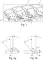
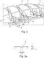
- Fig. 1 and Fig. 3 each show an oblique view of a circumferential section of a shoulder-side tread block row 1 of a tread of a pneumatic vehicle tire.
- the row of tread blocks 1 is composed in the circumferential direction of the pneumatic vehicle tire from a plurality of tread blocks 2 which are separated from one another by a transverse groove 3.
- the lateral edge of the ground contact area of the tread is indicated in each case by a dashed line.
- the ground contact area corresponds to the statically determined footprint according to ETRTO standards (load at 70% of the maximum load capacity with an internal pressure of 85% according to ETRTO standard).
- the shoulder-side row of tread blocks 1 is outside the ground contact area with a shoulder flank 4 which extends to a side wall of the tire (not shown), which is oriented essentially in the radial direction and, when viewed from the side of the tire, is circular - interrupted by transverse grooves 5, 5 'of the transverse grooves 3 - runs around the tire, Mistake.
- the rolling direction of the tire when driving forward is indicated by an arrow R in each case.
- the width of the transverse groove runs 5 ( Fig. 1 ) corresponds to the width of the transverse grooves 3 at the edge of the ground contact area, the width of the transverse groove outlets 5 '( Fig. 3 ) becomes larger towards their ends.
- flank grooves 6, 6' ( Fig. 1 ) and 6 "( Fig. 2 ), which extend at an obtuse angle ⁇ of 100 ° to 140 °, in particular up to 130 °, to the transverse groove runs 5, 5 ', the angle ⁇ being the angle between the center lines of the relevant grooves 5, 5', 6, 6 'and 6 ".
- the flank grooves 6, 6' and 6" thus run almost in the circumferential direction on the shoulder flank 4 and preferably in such a way that they are inclined towards the side wall and in this way to the circumferential direction at an angle ⁇ of preferably at least 5 ° run.
- the flank grooves 6, 6 ′ and 6 ′′ also have a length l 1 of 15.0 mm to 25.0 mm, which is determined starting from the inside corner of the kinks.
- the flank grooves 6, 6 'and 6 ′′ have a width b 1 on the outside of the shoulder flank 4, which continuously decreases between the kink to the respective transverse groove outlet 5, 5' and its end and over the majority of the course of the flank grooves 6, 6 'and 6 "is 1.5mm to 3.0mm.
- the flank grooves 6, 6 'and 6 " also have a depth t 2 ( Figures 2a, 2b ), which, starting from the depth t 1 of the transverse groove runs 5, 5 ', is reduced at the kink to its end and is at least 0.5 mm here.
- flank groove 6 ends at the shoulder flank 5 as a "closed” groove
- flank grooves 6 ′ and 6 ′′ are followed by additional groove sections 7a, 7b via further kinks
- the groove sections 7a essentially in run in the radial direction
- the groove sections 7b are oriented in the circumferential direction, but opposite to the flank grooves 6 ', 6 ".
- the groove sections 7a, 7b are shallow, their depth corresponds at the highest to the smallest depth of the flank grooves 6' and 6"
- their extension lengths l 2 ( from inside corner to inside corner) and l 3 (from inside corner to end) are 2.0 mm to 7.0 mm.
- each flank groove 6, 6 'and 6 has a cross-section that widens towards the outside of the shoulder flank 5, a groove bottom 6c and groove walls 6a, 6b running towards the outside of the shoulder flank 5, the groove wall 6b being the one that corresponds to the respective flank groove 6 , 6 'and 6 "are limited in the direction of the side wall, not shown.
- the groove wall 6a runs at an angle ⁇ to a perpendicular to the outside of the shoulder flank 5 of 20 ° to 60 °, in particular 30 ° to 50 °
- the groove wall 6b runs to a perpendicular to the outside of the shoulder flank at an angle ⁇ 'of 4 ° up to 15 °, in particular up to 10 °.
- the grooved wall 6b thus acts as a snow-compacting "edge", so that snow that collects and compacts in the flank grooves 6, 6 'and 6 "supports the effect of snow-snow friction well.
- the embodiment variant shown is provided exclusively on the shoulder flank 4 ′′.
- the additional groove sections 7b also each have an end 17 shaped like a V or arrowhead in plan view 6 ′′ each connected by an incision 8.
- the incisions 8 run straight, essentially parallel to or in continuation of the flank grooves 6 ′′, have a width b 2 on the outside of the shoulder flank 4 of 0.5 mm to 1.3 mm and an in particular constant depth t 3 of likewise 0.5 mm to 1.3 mm, as shown in Fig.
- the cross section of the incisions 8 is rounded.
- the incisions 8 provide additional grip edges to improve traction on deep snow.
Landscapes
- Engineering & Computer Science (AREA)
- Mechanical Engineering (AREA)
- Tires In General (AREA)
Claims (14)
- Pneumatique de véhicule muni de parois latérales et muni d'une bande de roulement profilée conçue directionnellement, de telle sorte que le pneumatique de véhicule doit être monté sur le véhicule avec une direction de roulement déterminée (R) en marche avant,la bande de roulement comprenant dans sa surface de contact avec le sol au moins une série de blocs profilés côté épaulement (1), divisée par des rainures transversales (3) en blocs profilés (2), qui présente à l'extérieur de la surface de contact avec le sol un flanc d'épaulement (4), dans lequel des sorties de rainures transversales (5, 5') s'étendent dans le prolongement des rainures transversales (3) et en direction radiale, dont la profondeur diminue dans la direction de la paroi latérale, des rainures de flanc (6, 6', 6'') étant contiguës aux sorties de rainures transversales (5, 5') par l'intermédiaire à chaque fois d'un point d'inflexion, qui s'étendent à l'encontre de la direction de roulement (R) en marche avant lorsque le pneumatique de véhicule est monté sur le véhicule,caractérisé en ce queles rainures de flanc (6, 6', 6'') sont contiguës aux sorties de rainures transversales (5, 5') avec un angle obtus (α) et comprennent des parois de rainure (6a, 6b) s'étendant jusqu'au côté extérieur de flanc d'épaulement, parmi lesquelles la paroi de rainure (6b), plus éloignée de la bande de roulement, s'étend à un angle (γ') plus petit par rapport à une verticale sur le côté extérieur de flanc d'épaulement que l'autre paroi de rainure (6a).
- Pneumatique de véhicule selon la revendication 1, caractérisé en ce que l'angle (γ') de la paroi de rainure (6b) s'étendant à l'angle plus petit par rapport à une verticale sur le côté extérieur de flanc d'épaulement est de 4° à 15°, notamment de jusqu'à 10°.
- Pneumatique de véhicule selon la revendication 1 ou 2, caractérisé en ce que l'angle (γ) de la paroi de rainure (6a) s'étendant à l'angle plus grand par rapport à une verticale sur le côté extérieur de flanc d'épaulement est de 20° à 60°, notamment de 30° à 50°.
- Pneumatique de véhicule selon l'une quelconque des revendications 1 à 3, caractérisé en ce que l'angle obtus (α) entre les sorties de rainures transversales (5, 5') et les rainures de flanc (6, 6', 6'') est de 100° à 140°, notamment de jusqu'à 130°, les rainures de flanc (6, 6', 6'') étant de préférence inclinées en direction de la paroi latérale en vue de dessus sur le flanc d'épaulement (4).
- Pneumatique de véhicule selon l'une quelconque des revendications 1 à 4, caractérisé en ce que les rainures de flanc (6, 6', 6'') présentent entre les coins intérieurs des points d'inflexion et leurs extrémités une longueur (l1) de 15,0 mm à 25,0 mm.
- Pneumatique de véhicule selon l'une quelconque des revendications 1 à 5, caractérisé en ce que les rainures de flanc (6, 6', 6'') présentent au moins sur la majeure partie de leur étendue une largeur (b1) de 1,5 mm à 3,0 mm.
- Pneumatique de véhicule selon l'une quelconque des revendications 1 à 6, caractérisé en ce que les rainures de flanc (6, 6', 6'') présentent au moins sur la majeure partie de leur étendue une largeur (b1) qui devient plus petite en direction de leurs extrémités à partir des points d'inflexion vers les sorties de rainures transversales (5, 5').
- Pneumatique de véhicule selon l'une quelconque des revendications 1 à 7, caractérisé en ce que les rainures de flanc (6, 6', 6'') présentent une profondeur (t2) de 0,5 mm à 2,5 mm.
- Pneumatique de véhicule selon l'une quelconque des revendications 1 à 8, caractérisé en ce que les rainures de flanc (6, 6', 6'') présentent une profondeur (t2) qui devient plus petite en direction de leurs extrémités à partir des points d'inflexion vers les sorties de rainures transversales (5, 5').
- Pneumatique de véhicule selon l'une quelconque des revendications 1 à 9, caractérisé en ce que des sections de rainure (7a), qui s'étendent dans la direction radiale, sont additionnellement contiguës aux rainures de flanc (6', 6'') par l'intermédiaire de points d'inflexion.
- Pneumatique de véhicule selon la revendication 10, caractérisé en ce qu'une section de rainure supplémentaire (7b), qui s'étend en sens inverse des rainures de flanc (6', 6''), est contiguë aux sections de rainure additionnelles (7a) par l'intermédiaire à chaque fois d'un point d'inflexion.
- Pneumatique de véhicule selon la revendication 10 ou 11, caractérisé en ce que les sections de rainure additionnelles (7a) et les sections de rainure supplémentaires (7b) présentent à chaque fois une longueur (l2, l3) de 3,0 mm à 7,0 mm.
- Pneumatique de véhicule selon l'une quelconque des revendications 1 à 12, caractérisé en ce qu'une entaille (8) ayant une largeur (b3) et une profondeur (t2) de 0,5 mm à 1,3 mm s'étend à chaque fois dans le prolongement des rainures de flanc (6").
- Pneumatique de véhicule selon la revendication 13, caractérisé en ce que l'entaille (8) relie l'extrémité d'une section de rainure (7b) s'étendant en sens inverse de la rainure de flanc (6'') avec le coin extérieur suivant dans la direction circonférentielle du point d'inflexion entre la rainure de flanc (6'') et la section de rainure (7a) contiguë à celle-ci.
Applications Claiming Priority (1)
| Application Number | Priority Date | Filing Date | Title |
|---|---|---|---|
| DE102019200901.8A DE102019200901A1 (de) | 2019-01-24 | 2019-01-24 | Fahrzeugluftreifen |
Publications (2)
| Publication Number | Publication Date |
|---|---|
| EP3686034A1 EP3686034A1 (fr) | 2020-07-29 |
| EP3686034B1 true EP3686034B1 (fr) | 2021-10-20 |
Family
ID=68470316
Family Applications (1)
| Application Number | Title | Priority Date | Filing Date |
|---|---|---|---|
| EP19207349.2A Active EP3686034B1 (fr) | 2019-01-24 | 2019-11-06 | Pneumatiques de véhicule |
Country Status (2)
| Country | Link |
|---|---|
| EP (1) | EP3686034B1 (fr) |
| DE (1) | DE102019200901A1 (fr) |
Family Cites Families (11)
| Publication number | Priority date | Publication date | Assignee | Title |
|---|---|---|---|---|
| JP3676534B2 (ja) * | 1997-04-10 | 2005-07-27 | 株式会社ブリヂストン | 空気入りタイヤ |
| JP3930391B2 (ja) * | 2002-07-29 | 2007-06-13 | 住友ゴム工業株式会社 | 空気入りタイヤ |
| JP4829994B2 (ja) * | 2009-04-06 | 2011-12-07 | 住友ゴム工業株式会社 | 空気入りタイヤ |
| DE102010060255B4 (de) * | 2010-10-29 | 2020-09-24 | Continental Reifen Deutschland Gmbh | Laufstreifenprofil eines Fahrzeugluftreifens |
| JP5731852B2 (ja) * | 2011-02-24 | 2015-06-10 | 株式会社ブリヂストン | タイヤ |
| JP5519721B2 (ja) * | 2012-04-05 | 2014-06-11 | 株式会社ブリヂストン | 空気入りタイヤ |
| JP5945258B2 (ja) * | 2013-09-11 | 2016-07-05 | 住友ゴム工業株式会社 | 空気入りタイヤ |
| JP6400423B2 (ja) | 2014-10-09 | 2018-10-03 | 東洋ゴム工業株式会社 | 空気入りタイヤ |
| DE102015214483A1 (de) | 2015-07-30 | 2017-02-02 | Continental Reifen Deutschland Gmbh | Fahrzeugluftreifen |
| DE102016218981A1 (de) * | 2016-09-30 | 2018-04-05 | Continental Reifen Deutschland Gmbh | Fahrzeugluftreifen |
| DE102017206383A1 (de) | 2017-04-13 | 2018-10-18 | Continental Reifen Deutschland Gmbh | Fahrzeugluftreifen |
-
2019
- 2019-01-24 DE DE102019200901.8A patent/DE102019200901A1/de not_active Withdrawn
- 2019-11-06 EP EP19207349.2A patent/EP3686034B1/fr active Active
Also Published As
| Publication number | Publication date |
|---|---|
| DE102019200901A1 (de) | 2020-07-30 |
| EP3686034A1 (fr) | 2020-07-29 |
Similar Documents
| Publication | Publication Date | Title |
|---|---|---|
| EP3589501B1 (fr) | Pneumatique de véhicule | |
| EP3589500B1 (fr) | Pneumatique de véhicule | |
| EP3388256B1 (fr) | Pneumatique de véhicule | |
| EP3256334B1 (fr) | Pneumatique de véhicule | |
| EP3300926B1 (fr) | Pneumatiques de véhicule | |
| EP3009275B1 (fr) | Pneumatiques de vehicule | |
| DE102019213044A1 (de) | Fahrzeugluftreifen | |
| EP3724006A1 (fr) | Pneumatiques pour véhicules utilitaires | |
| EP0773117A1 (fr) | Profil de bande de roulement non-directionnel pour un bandage pneumatique avec une structure de profil contenant des blocs | |
| EP3441241B1 (fr) | Pneumatique de véhicule | |
| EP2138329B1 (fr) | Bande de roulement pour pneumatique | |
| DE102008029659A1 (de) | Fahrzeugluftreifen | |
| EP3300925B1 (fr) | Pneumatiques de véhicule | |
| EP2594416B1 (fr) | Zone lateral de bande de roulement | |
| EP3686034B1 (fr) | Pneumatiques de véhicule | |
| EP3888949B1 (fr) | Pneumatique de véhicule | |
| EP3663105B1 (fr) | Pneu de véhicule | |
| DE102008029658A1 (de) | Fahrzeugluftreifen | |
| EP4058304B1 (fr) | Pneumatique de véhicule | |
| DE102017215185A1 (de) | Fahrzeugluftreifen | |
| EP3659827B1 (fr) | Pneumatiques de véhicule comportant un profil de bande de roulement à une contre-dépouille | |
| EP3418076B1 (fr) | Pneumatique de véhicule | |
| EP1535759B1 (fr) | Bandage pneumatique | |
| EP3130484B1 (fr) | Pneumatique de véhicule | |
| EP3831619A1 (fr) | Pneumatique de véhicule |
Legal Events
| Date | Code | Title | Description |
|---|---|---|---|
| PUAI | Public reference made under article 153(3) epc to a published international application that has entered the european phase |
Free format text: ORIGINAL CODE: 0009012 |
|
| STAA | Information on the status of an ep patent application or granted ep patent |
Free format text: STATUS: THE APPLICATION HAS BEEN PUBLISHED |
|
| AK | Designated contracting states |
Kind code of ref document: A1 Designated state(s): AL AT BE BG CH CY CZ DE DK EE ES FI FR GB GR HR HU IE IS IT LI LT LU LV MC MK MT NL NO PL PT RO RS SE SI SK SM TR |
|
| AX | Request for extension of the european patent |
Extension state: BA ME |
|
| RAP1 | Party data changed (applicant data changed or rights of an application transferred) |
Owner name: CONTINENTAL REIFEN DEUTSCHLAND GMBH |
|
| STAA | Information on the status of an ep patent application or granted ep patent |
Free format text: STATUS: REQUEST FOR EXAMINATION WAS MADE |
|
| 17P | Request for examination filed |
Effective date: 20210129 |
|
| RBV | Designated contracting states (corrected) |
Designated state(s): AL AT BE BG CH CY CZ DE DK EE ES FI FR GB GR HR HU IE IS IT LI LT LU LV MC MK MT NL NO PL PT RO RS SE SI SK SM TR |
|
| GRAP | Despatch of communication of intention to grant a patent |
Free format text: ORIGINAL CODE: EPIDOSNIGR1 |
|
| STAA | Information on the status of an ep patent application or granted ep patent |
Free format text: STATUS: GRANT OF PATENT IS INTENDED |
|
| INTG | Intention to grant announced |
Effective date: 20210521 |
|
| GRAS | Grant fee paid |
Free format text: ORIGINAL CODE: EPIDOSNIGR3 |
|
| GRAA | (expected) grant |
Free format text: ORIGINAL CODE: 0009210 |
|
| STAA | Information on the status of an ep patent application or granted ep patent |
Free format text: STATUS: THE PATENT HAS BEEN GRANTED |
|
| AK | Designated contracting states |
Kind code of ref document: B1 Designated state(s): AL AT BE BG CH CY CZ DE DK EE ES FI FR GB GR HR HU IE IS IT LI LT LU LV MC MK MT NL NO PL PT RO RS SE SI SK SM TR |
|
| REG | Reference to a national code |
Ref country code: GB Ref legal event code: FG4D Free format text: NOT ENGLISH |
|
| REG | Reference to a national code |
Ref country code: CH Ref legal event code: EP |
|
| REG | Reference to a national code |
Ref country code: DE Ref legal event code: R096 Ref document number: 502019002545 Country of ref document: DE |
|
| REG | Reference to a national code |
Ref country code: IE Ref legal event code: FG4D Free format text: LANGUAGE OF EP DOCUMENT: GERMAN |
|
| REG | Reference to a national code |
Ref country code: AT Ref legal event code: REF Ref document number: 1439643 Country of ref document: AT Kind code of ref document: T Effective date: 20211115 |
|
| REG | Reference to a national code |
Ref country code: SE Ref legal event code: TRGR |
|
| REG | Reference to a national code |
Ref country code: LT Ref legal event code: MG9D |
|
| REG | Reference to a national code |
Ref country code: NL Ref legal event code: MP Effective date: 20211020 |
|
| PG25 | Lapsed in a contracting state [announced via postgrant information from national office to epo] |
Ref country code: RS Free format text: LAPSE BECAUSE OF FAILURE TO SUBMIT A TRANSLATION OF THE DESCRIPTION OR TO PAY THE FEE WITHIN THE PRESCRIBED TIME-LIMIT Effective date: 20211020 Ref country code: LT Free format text: LAPSE BECAUSE OF FAILURE TO SUBMIT A TRANSLATION OF THE DESCRIPTION OR TO PAY THE FEE WITHIN THE PRESCRIBED TIME-LIMIT Effective date: 20211020 Ref country code: FI Free format text: LAPSE BECAUSE OF FAILURE TO SUBMIT A TRANSLATION OF THE DESCRIPTION OR TO PAY THE FEE WITHIN THE PRESCRIBED TIME-LIMIT Effective date: 20211020 Ref country code: BG Free format text: LAPSE BECAUSE OF FAILURE TO SUBMIT A TRANSLATION OF THE DESCRIPTION OR TO PAY THE FEE WITHIN THE PRESCRIBED TIME-LIMIT Effective date: 20220120 |
|
| PG25 | Lapsed in a contracting state [announced via postgrant information from national office to epo] |
Ref country code: IS Free format text: LAPSE BECAUSE OF FAILURE TO SUBMIT A TRANSLATION OF THE DESCRIPTION OR TO PAY THE FEE WITHIN THE PRESCRIBED TIME-LIMIT Effective date: 20220220 Ref country code: PT Free format text: LAPSE BECAUSE OF FAILURE TO SUBMIT A TRANSLATION OF THE DESCRIPTION OR TO PAY THE FEE WITHIN THE PRESCRIBED TIME-LIMIT Effective date: 20220221 Ref country code: PL Free format text: LAPSE BECAUSE OF FAILURE TO SUBMIT A TRANSLATION OF THE DESCRIPTION OR TO PAY THE FEE WITHIN THE PRESCRIBED TIME-LIMIT Effective date: 20211020 Ref country code: NO Free format text: LAPSE BECAUSE OF FAILURE TO SUBMIT A TRANSLATION OF THE DESCRIPTION OR TO PAY THE FEE WITHIN THE PRESCRIBED TIME-LIMIT Effective date: 20220120 Ref country code: NL Free format text: LAPSE BECAUSE OF FAILURE TO SUBMIT A TRANSLATION OF THE DESCRIPTION OR TO PAY THE FEE WITHIN THE PRESCRIBED TIME-LIMIT Effective date: 20211020 Ref country code: LV Free format text: LAPSE BECAUSE OF FAILURE TO SUBMIT A TRANSLATION OF THE DESCRIPTION OR TO PAY THE FEE WITHIN THE PRESCRIBED TIME-LIMIT Effective date: 20211020 Ref country code: HR Free format text: LAPSE BECAUSE OF FAILURE TO SUBMIT A TRANSLATION OF THE DESCRIPTION OR TO PAY THE FEE WITHIN THE PRESCRIBED TIME-LIMIT Effective date: 20211020 Ref country code: GR Free format text: LAPSE BECAUSE OF FAILURE TO SUBMIT A TRANSLATION OF THE DESCRIPTION OR TO PAY THE FEE WITHIN THE PRESCRIBED TIME-LIMIT Effective date: 20220121 Ref country code: ES Free format text: LAPSE BECAUSE OF FAILURE TO SUBMIT A TRANSLATION OF THE DESCRIPTION OR TO PAY THE FEE WITHIN THE PRESCRIBED TIME-LIMIT Effective date: 20211020 |
|
| REG | Reference to a national code |
Ref country code: DE Ref legal event code: R097 Ref document number: 502019002545 Country of ref document: DE |
|
| PG25 | Lapsed in a contracting state [announced via postgrant information from national office to epo] |
Ref country code: SM Free format text: LAPSE BECAUSE OF FAILURE TO SUBMIT A TRANSLATION OF THE DESCRIPTION OR TO PAY THE FEE WITHIN THE PRESCRIBED TIME-LIMIT Effective date: 20211020 Ref country code: SK Free format text: LAPSE BECAUSE OF FAILURE TO SUBMIT A TRANSLATION OF THE DESCRIPTION OR TO PAY THE FEE WITHIN THE PRESCRIBED TIME-LIMIT Effective date: 20211020 Ref country code: RO Free format text: LAPSE BECAUSE OF FAILURE TO SUBMIT A TRANSLATION OF THE DESCRIPTION OR TO PAY THE FEE WITHIN THE PRESCRIBED TIME-LIMIT Effective date: 20211020 Ref country code: MC Free format text: LAPSE BECAUSE OF FAILURE TO SUBMIT A TRANSLATION OF THE DESCRIPTION OR TO PAY THE FEE WITHIN THE PRESCRIBED TIME-LIMIT Effective date: 20211020 Ref country code: LU Free format text: LAPSE BECAUSE OF NON-PAYMENT OF DUE FEES Effective date: 20211106 Ref country code: EE Free format text: LAPSE BECAUSE OF FAILURE TO SUBMIT A TRANSLATION OF THE DESCRIPTION OR TO PAY THE FEE WITHIN THE PRESCRIBED TIME-LIMIT Effective date: 20211020 Ref country code: DK Free format text: LAPSE BECAUSE OF FAILURE TO SUBMIT A TRANSLATION OF THE DESCRIPTION OR TO PAY THE FEE WITHIN THE PRESCRIBED TIME-LIMIT Effective date: 20211020 Ref country code: CZ Free format text: LAPSE BECAUSE OF FAILURE TO SUBMIT A TRANSLATION OF THE DESCRIPTION OR TO PAY THE FEE WITHIN THE PRESCRIBED TIME-LIMIT Effective date: 20211020 Ref country code: BE Free format text: LAPSE BECAUSE OF NON-PAYMENT OF DUE FEES Effective date: 20211130 |
|
| REG | Reference to a national code |
Ref country code: BE Ref legal event code: MM Effective date: 20211130 |
|
| PLBE | No opposition filed within time limit |
Free format text: ORIGINAL CODE: 0009261 |
|
| STAA | Information on the status of an ep patent application or granted ep patent |
Free format text: STATUS: NO OPPOSITION FILED WITHIN TIME LIMIT |
|
| 26N | No opposition filed |
Effective date: 20220721 |
|
| PG25 | Lapsed in a contracting state [announced via postgrant information from national office to epo] |
Ref country code: IE Free format text: LAPSE BECAUSE OF NON-PAYMENT OF DUE FEES Effective date: 20211106 Ref country code: AL Free format text: LAPSE BECAUSE OF FAILURE TO SUBMIT A TRANSLATION OF THE DESCRIPTION OR TO PAY THE FEE WITHIN THE PRESCRIBED TIME-LIMIT Effective date: 20211020 |
|
| PG25 | Lapsed in a contracting state [announced via postgrant information from national office to epo] |
Ref country code: SI Free format text: LAPSE BECAUSE OF FAILURE TO SUBMIT A TRANSLATION OF THE DESCRIPTION OR TO PAY THE FEE WITHIN THE PRESCRIBED TIME-LIMIT Effective date: 20211020 Ref country code: FR Free format text: LAPSE BECAUSE OF NON-PAYMENT OF DUE FEES Effective date: 20211220 |
|
| PG25 | Lapsed in a contracting state [announced via postgrant information from national office to epo] |
Ref country code: IT Free format text: LAPSE BECAUSE OF FAILURE TO SUBMIT A TRANSLATION OF THE DESCRIPTION OR TO PAY THE FEE WITHIN THE PRESCRIBED TIME-LIMIT Effective date: 20211020 |
|
| PG25 | Lapsed in a contracting state [announced via postgrant information from national office to epo] |
Ref country code: CY Free format text: LAPSE BECAUSE OF FAILURE TO SUBMIT A TRANSLATION OF THE DESCRIPTION OR TO PAY THE FEE WITHIN THE PRESCRIBED TIME-LIMIT Effective date: 20211020 |
|
| REG | Reference to a national code |
Ref country code: CH Ref legal event code: PL |
|
| PG25 | Lapsed in a contracting state [announced via postgrant information from national office to epo] |
Ref country code: LI Free format text: LAPSE BECAUSE OF NON-PAYMENT OF DUE FEES Effective date: 20221130 Ref country code: HU Free format text: LAPSE BECAUSE OF FAILURE TO SUBMIT A TRANSLATION OF THE DESCRIPTION OR TO PAY THE FEE WITHIN THE PRESCRIBED TIME-LIMIT; INVALID AB INITIO Effective date: 20191106 Ref country code: CH Free format text: LAPSE BECAUSE OF NON-PAYMENT OF DUE FEES Effective date: 20221130 |
|
| PGFP | Annual fee paid to national office [announced via postgrant information from national office to epo] |
Ref country code: SE Payment date: 20231120 Year of fee payment: 5 Ref country code: DE Payment date: 20231130 Year of fee payment: 5 |
|
| REG | Reference to a national code |
Ref country code: DE Ref legal event code: R081 Ref document number: 502019002545 Country of ref document: DE Owner name: CONTINENTAL REIFEN DEUTSCHLAND GMBH, DE Free format text: FORMER OWNER: CONTINENTAL REIFEN DEUTSCHLAND GMBH, 30165 HANNOVER, DE |
|
| PG25 | Lapsed in a contracting state [announced via postgrant information from national office to epo] |
Ref country code: MK Free format text: LAPSE BECAUSE OF FAILURE TO SUBMIT A TRANSLATION OF THE DESCRIPTION OR TO PAY THE FEE WITHIN THE PRESCRIBED TIME-LIMIT Effective date: 20211020 |