EP3683099B1 - Türverriegelungsstromversorgungsvorrichtung, türverriegelungsstromversorgungssystem und fahrzeug damit - Google Patents
Türverriegelungsstromversorgungsvorrichtung, türverriegelungsstromversorgungssystem und fahrzeug damit Download PDFInfo
- Publication number
- EP3683099B1 EP3683099B1 EP18855618.7A EP18855618A EP3683099B1 EP 3683099 B1 EP3683099 B1 EP 3683099B1 EP 18855618 A EP18855618 A EP 18855618A EP 3683099 B1 EP3683099 B1 EP 3683099B1
- Authority
- EP
- European Patent Office
- Prior art keywords
- power supply
- storage unit
- electricity storage
- door latch
- door
- Prior art date
- Legal status (The legal status is an assumption and is not a legal conclusion. Google has not performed a legal analysis and makes no representation as to the accuracy of the status listed.)
- Active
Links
Images

Classifications
-
- H02J7/825—
-
- B—PERFORMING OPERATIONS; TRANSPORTING
- B60—VEHICLES IN GENERAL
- B60R—VEHICLES, VEHICLE FITTINGS, OR VEHICLE PARTS, NOT OTHERWISE PROVIDED FOR
- B60R16/00—Electric or fluid circuits specially adapted for vehicles and not otherwise provided for; Arrangement of elements of electric or fluid circuits specially adapted for vehicles and not otherwise provided for
- B60R16/02—Electric or fluid circuits specially adapted for vehicles and not otherwise provided for; Arrangement of elements of electric or fluid circuits specially adapted for vehicles and not otherwise provided for electric constitutive elements
- B60R16/03—Electric or fluid circuits specially adapted for vehicles and not otherwise provided for; Arrangement of elements of electric or fluid circuits specially adapted for vehicles and not otherwise provided for electric constitutive elements for supply of electrical power to vehicle subsystems or for
- B60R16/033—Electric or fluid circuits specially adapted for vehicles and not otherwise provided for; Arrangement of elements of electric or fluid circuits specially adapted for vehicles and not otherwise provided for electric constitutive elements for supply of electrical power to vehicle subsystems or for characterised by the use of electrical cells or batteries
-
- B—PERFORMING OPERATIONS; TRANSPORTING
- B60—VEHICLES IN GENERAL
- B60R—VEHICLES, VEHICLE FITTINGS, OR VEHICLE PARTS, NOT OTHERWISE PROVIDED FOR
- B60R25/00—Fittings or systems for preventing or indicating unauthorised use or theft of vehicles
- B60R25/40—Features of the power supply for the anti-theft system, e.g. anti-theft batteries, back-up power supply or means to save battery power
- B60R25/403—Power supply in the vehicle
-
- E—FIXED CONSTRUCTIONS
- E05—LOCKS; KEYS; WINDOW OR DOOR FITTINGS; SAFES
- E05B—LOCKS; ACCESSORIES THEREFOR; HANDCUFFS
- E05B81/00—Power-actuated vehicle locks
- E05B81/54—Electrical circuits
- E05B81/80—Electrical circuits characterised by the power supply; Emergency power operation
-
- E—FIXED CONSTRUCTIONS
- E05—LOCKS; KEYS; WINDOW OR DOOR FITTINGS; SAFES
- E05B—LOCKS; ACCESSORIES THEREFOR; HANDCUFFS
- E05B81/00—Power-actuated vehicle locks
- E05B81/54—Electrical circuits
- E05B81/80—Electrical circuits characterised by the power supply; Emergency power operation
- E05B81/86—Electrical circuits characterised by the power supply; Emergency power operation using capacitors
-
- H—ELECTRICITY
- H02—GENERATION; CONVERSION OR DISTRIBUTION OF ELECTRIC POWER
- H02J—CIRCUIT ARRANGEMENTS OR SYSTEMS FOR SUPPLYING OR DISTRIBUTING ELECTRIC POWER; SYSTEMS FOR STORING ELECTRIC ENERGY
- H02J50/00—Circuit arrangements or systems for wireless supply or distribution of electric power
- H02J50/10—Circuit arrangements or systems for wireless supply or distribution of electric power using inductive coupling
-
- H—ELECTRICITY
- H02—GENERATION; CONVERSION OR DISTRIBUTION OF ELECTRIC POWER
- H02J—CIRCUIT ARRANGEMENTS OR SYSTEMS FOR SUPPLYING OR DISTRIBUTING ELECTRIC POWER; SYSTEMS FOR STORING ELECTRIC ENERGY
- H02J7/00—Circuit arrangements for charging or depolarising batteries or for supplying loads from batteries
- H02J7/34—Parallel operation in networks using both storage and other DC sources, e.g. providing buffering
- H02J7/342—The other DC source being a battery actively interacting with the first one, i.e. battery to battery charging
-
- H—ELECTRICITY
- H02—GENERATION; CONVERSION OR DISTRIBUTION OF ELECTRIC POWER
- H02J—CIRCUIT ARRANGEMENTS OR SYSTEMS FOR SUPPLYING OR DISTRIBUTING ELECTRIC POWER; SYSTEMS FOR STORING ELECTRIC ENERGY
- H02J7/00—Circuit arrangements for charging or depolarising batteries or for supplying loads from batteries
- H02J7/34—Parallel operation in networks using both storage and other DC sources, e.g. providing buffering
- H02J7/345—Parallel operation in networks using both storage and other DC sources, e.g. providing buffering using capacitors as storage or buffering devices
-
- H02J7/865—
-
- H02J2105/30—
-
- H—ELECTRICITY
- H02—GENERATION; CONVERSION OR DISTRIBUTION OF ELECTRIC POWER
- H02J—CIRCUIT ARRANGEMENTS OR SYSTEMS FOR SUPPLYING OR DISTRIBUTING ELECTRIC POWER; SYSTEMS FOR STORING ELECTRIC ENERGY
- H02J2207/00—Indexing scheme relating to details of circuit arrangements for charging or depolarising batteries or for supplying loads from batteries
- H02J2207/40—Indexing scheme relating to details of circuit arrangements for charging or depolarising batteries or for supplying loads from batteries adapted for charging from various sources, e.g. AC, DC or multivoltage
-
- H—ELECTRICITY
- H02—GENERATION; CONVERSION OR DISTRIBUTION OF ELECTRIC POWER
- H02J—CIRCUIT ARRANGEMENTS OR SYSTEMS FOR SUPPLYING OR DISTRIBUTING ELECTRIC POWER; SYSTEMS FOR STORING ELECTRIC ENERGY
- H02J2207/00—Indexing scheme relating to details of circuit arrangements for charging or depolarising batteries or for supplying loads from batteries
- H02J2207/50—Charging of capacitors, supercapacitors, ultra-capacitors or double layer capacitors
-
- H—ELECTRICITY
- H02—GENERATION; CONVERSION OR DISTRIBUTION OF ELECTRIC POWER
- H02J—CIRCUIT ARRANGEMENTS OR SYSTEMS FOR SUPPLYING OR DISTRIBUTING ELECTRIC POWER; SYSTEMS FOR STORING ELECTRIC ENERGY
- H02J50/00—Circuit arrangements or systems for wireless supply or distribution of electric power
Definitions
- the present invention relates to a door latch power supply device used for various kinds of vehicles, a door latch power supply system, and a vehicle including the system.
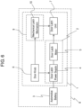
- FIG. 6 is a block diagram of conventional door latch system 1.
- Door latch system 1 includes normal operation mechanism 2 and emergency operation mechanism 9.
- Normal operation mechanism 2 includes door latch power supply device 4 that receives power supply from automotive battery 3, and door latch motor 5 driven by door latch power supply device 4.
- an instruction for placing door latch unit 7 in an unlatched state is received from door handle 6 to operate door latch power supply device 4 and door latch motor 5.
- Emergency operation mechanism 9 which is a redundant function, places door latch unit 7 in an unlatched state, thereby enabling to enter vehicle 8 for maintenance when automotive battery 3 runs out, e.g., in the case where vehicle 8 is not moved for a long period of time.
- Emergency operation mechanism 9 includes mechanical latch mechanism 10 operating mechanically in response to an instruction for placing door latch unit 7 in an unlatched state from door handle 6.
- a conventional door latch system similar to door latch system 1 is disclosed in, e.g. PTL 1.
- JP 2007-32140 discloses the preamble of claim 1.
- JP 2015-140639 A discloses a vehicle door locking system, which can receive power either from a vehicle battery of wirelessly from a battery of a portable vehicle key.
- US 2016/0153216 A1 discloses a vehicle door locking system, which can receive power either from a vehicle battery or from a power storage within the vehicle door locking system, which power storage is charged by the vehicle battery.
- a door latch power supply device includes an electricity storage unit, a charger, a discharger, a contactless power receiver, an input port configured to be connected to an external power supply, an output port configured to be connected to an actuator, and an operation signal receiver configured to receive an operation signal sent in response to an operation for opening a door. While an input voltage input to the input port is higher than or equal to a first input threshold, the charger operates using power supplied from the external power supply so as to cause a storage voltage of the electricity storage unit to become a first storage voltage value, and the discharger outputs power in the electricity storage unit to the output port to place the actuator in the unlatched state in response to the operation signal received by the operation signal receiver.
- the charger While the input voltage is lower than the first input threshold, the charger operates using power supplied from the contactless power receiver so as to cause the storage voltage to become a second storage voltage value, and then the discharger outputs power in the electricity storage unit to the output port to place the actuator in the unlatched state in response to the operation signal received.
- the second storage voltage value is higher than the first storage voltage value.
- This door latch power supply device reduces the weight of a vehicle.
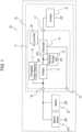
- FIG. 1 is a circuit block diagram of door latch power supply device 11 in accordance with an exemplary embodiment.
- Door latch power supply device 11 includes electricity storage unit 12, charger 13, discharger 14, contactless power receiver 15, input port 16, output port 17, operation signal receiver 18, and controller 26.
- Charger 13 is connected to charging path 13A of electricity storage unit 12 to charge electricity storage unit 12.
- Discharger 14 is connected to discharging path 14A of electricity storage unit 12 to discharge electricity storage unit 12.
- Contactless power receiver 15 connected to charger 13 is configured to charge electricity storage unit 12 without contact.
- Input port 16 is connected to charger 13.
- Output port 17 is connected to discharger 14.
- Operation signal receiver 18 configured to receive an operation signal generated in the outside of door latch power supply device 11.
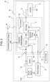
- FIG. 2 is a block diagram of vehicle 20 including door latch power supply device 11.
- FIG. 3 and FIG. 4 are timing charts of an operation of door latch power supply device 11. The configuration and operation of door latch power supply device 11 will be described below.
- Door latch power supply device 11, automotive battery 19 connected to input port 16 of door latch power supply device 11, actuator 21 connected to output port 17 of door latch power supply device 11, and electric device 21A are mounted onto body 23 of vehicle 20.
- Door 22 is provided in body 23.
- Door handle 24 connected to operation signal receiver 18 of door latch power supply device 11 is disposed in door 22.
- Automotive battery 19 is an external power supply provided outside door latch power supply device 11, and is a rechargeable battery, such as a lead storage battery or a lithium ion battery, capable of charging and discharging.
- Electric device 21A may be, e.g. a car audio device and a car navigation device.
- Actuator 21 is configured to selectively provide a latched state in which door 22 is latched and an unlatched state in which door 22 is not latched.
- a fastener In the latched state, a fastener is engaged with door 22, so that door 22 is latched and closed.
- a fastener In the unlatched state, a fastener is not engaged with door 22, so that door 22 can be opened. In other words, in the unlatched state, an operator just pulls or pushes door 22, thereby opening door 22. If no power is output from output port 17 of door latch power supply device 11, actuator 21 is in the latched state.
- actuator 21 is mounted onto body 23. When an operator operates door handle 24, actuator 21 is driven to operate as a result of that.
- An operator of vehicle 20 operates door handle 24 to open door 22.
- door handle 24 is connected to operation signal receiver 18 of door latch power supply device 11.
- operation signal receiver 18 receives an operation signal in response to the operation.
- Door handle 24 may be connected to operation signal receiver 18 directly or indirectly. In other words, door handle 24 may transmit the operation signal, or an electric circuit other than door handle 24 linked to door handle 24 may transmit the operation signal.
- Electricity storage unit 12 of door latch power supply device 11 includes one or more electricity storage elements.
- the electricity storage elements may employ rechargeable batteries or electric double layer capacitors, which can charge and discharge repetitively.
- the kind of electricity storage elements may be determined depending on an operation specification of door latch power supply device 11.
- door latch power supply device 11 employs an electric double layer capacitor as electricity storage unit 12.
- the electric double layer capacitor is excellent in weight saving and characteristics related to large current discharge.
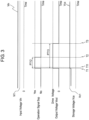
- FIG. 3 and FIG. 4 are timing charts showing an operation of door latch power supply device 11.
- FIG. 3 and FIG. 4 show input voltage Vin, operation signal Sop, output voltage Vout, and storage voltage Vca.
- horizontal axes indicate time
- vertical axes indicate the above-mentioned voltages and a value of the signal.
- Input threshold Vi1 is determined to be a minimum value that can operate electric device 21A mounted on vehicle 20.
- In door latch power supply device 11 input threshold Vi2 lower than input threshold Vi1 is defined.
- Input threshold Vi2 is set to be a minimum value that can operate charger 13 and discharger 14, or a minimum value required before a boost-up operation in order to obtain a predetermined voltage after the boost-up operation.
- Input voltage Vin detected at input port 16 is a voltage of automotive battery 19, and is compared with input threshold Vi1.
- automotive battery 19 is determined to be in a preferable state without any deterioration.
- the operation of comparing input voltage Vin with input threshold Vi1 may be performed repetitively and periodically at predetermined periods when vehicle 20 is left unused, or may be performed when operation signal receiver 18 receives an operation signal.
- charger 13 When controller 26 determines that input voltage Vin is higher than or equal to input threshold Vi1, charger 13 starts operation.
- the operation of charger 13 may be either of a boost-up operation or a stepping-down operation.
- Charger 13 charges electricity storage unit 12 so as to cause storage voltage Vca of electricity storage unit 12 to become storage voltage value Vc1.
- the operation of charger 13 which charges electricity storage unit 12 so as to cause storage voltage Vca of electricity storage unit 12 to become storage voltage value Vc1 may be performed repetitively and periodically at predetermined periods when vehicle 20 is left unused, or may be performed when operation signal receiver 18 receives operation signal Sop, similarly to the comparing operation mentioned above.
- controller 26 When vehicle 20 is stopped last time after completing its start-up, controller 26 operates charger 13 and discharger 14 so as to cause storage voltage Vca of electricity storage unit 12 to become storage voltage value Vc1 which is about 50% or less of a full charge voltage of the electric double layer capacitor in consideration of a life time of the electric double layer capacitor of electricity storage unit 12. After that, electricity storage unit 12 is left unused. This configuration hardly promotes degradation of electricity storage unit 12. If being left unused during the same period of time, the electric double layer capacitor which constitutes electricity storage unit 12 hardly cause a deterioration in voltage as compared with automotive battery 19. But if being left unused for a long time, storage voltage Vca decreases gradually. However, the decreasing amount of storage voltage Vca is small.
- the operation in which charger 13 charges storage voltage Vca of electricity storage unit 12 to storage voltage value Vc1 may be performed repetitively and periodically at predetermined periods when vehicle 20 is left unused, or may be performed when operation signal receiver 18 receives an operation signal. In both cases, the operation in which electricity storage unit 12 charges storage voltage Vca to storage voltage value Vc1 is completed in an extremely short period of time.
- operation signal receiver 18 When an operator operates door handle 24 at timing T1, operation signal receiver 18 receives operation signal Sop. As mentioned above, electricity storage unit 12 is charged before timing T1 such that storage voltage Vca becomes storage voltage value Vc1. Alternatively, when operation signal receiver 18 receives operation signal Sop at timing T1, in response to this, charger 13 charges electricity storage unit 12 so as to cause storage voltage Vca to become storage voltage value Vc1 instantly in response to the signal. For the operation of charging electricity storage unit 12 before timing T1 such that storage voltage Vca becomes storage voltage value Vc1, charger 13 may start the above-mentioned operation when external signal receiver 29 of door latch power supply device 11 receives an auxiliary signal from, e.g. a transmitter or the like possessed by an operator.
- auxiliary signal e.g. a transmitter or the like possessed by an operator.
- charger 13 may start the above-mentioned operation when door latch power supply device 11 detects the auxiliary signal transmitted from the transmitter held by the operator which is located away from vehicle 20 approaches vehicle 20.
- External signal receiver 29 is provided in vehicle 20. Information received by external signal receiver 29 is transmitted to door latch power supply device 11 although external signal receiver 29 is provided in door latch power supply device 11 in the figures.
- discharger 14 In period PT12 from timing T1 to timing T2 in which an operator operates door handle 24, or period PT13 from timing T1 to timing T3 which is longer than period PT12, discharger 14 outputs power in electricity storage unit 12 charged to have storage voltage value Vc1 through output port 17 to drive actuator 21. In other words, in period PT12 or period PT13, the power in electricity storage unit 12 is used to place actuator 21 in the unlatched state and allow door 22 to be openable.
- the operation of discharger 14 may be either of a boost-up operation or a stepping-down operation.
- charger 13 charges electricity storage unit 12 so as to cause storage voltage Vca to become storage voltage value Vc1 in response to the operation of door handle 24 may be performed simultaneously to the operation in which discharger 14 discharges the power in electricity storage unit 12 to output port 17.
- charger 13 may charge electricity storage unit 12 so as to cause storage voltage Vca to become storage voltage value Vc1.
- discharger 14 may discharge electricity storage unit 12 and output the power in electricity storage unit 12 to output port 17.
- charger 13 may first charge electricity storage unit 12 so as to cause storage voltage Vca to become storage voltage value Vc1.
- discharger 14 may discharge electricity storage unit 12 and start outputting the power in electricity storage unit 12 to output port 17 at subsequent timing T11 when charger 13 completes the above-mentioned charging operation, or immediately after charger 13 completes the above-mentioned charging operation.
- Input voltage Vin detected by input port 16 is a voltage of automotive battery 19. Input voltage Vin is compared with input threshold Vi1. When input voltage Vin is lower than input threshold Vi1, automotive battery 19 is determined to be deteriorated, i.e., not in a preferable state.
- the operation related to a comparison between input voltage Vin and input threshold Vi1 may be performed repetitively and periodically at predetermined periods when vehicle 20 is left unused, or may be performed when operation signal receiver 18 receives operation signal Sop.
- controller 26 is able to operate at a low voltage even if the voltage of automotive battery 19 is low and automotive battery 19 is deteriorated, i.e., not in a preferable state. Therefore, fundamental control, comparison, and determination are performed almost constantly or at any timing. In other words, controller 26 can operate even if the output voltage of automotive battery 19 has a value lower than input threshold Vi1 although input threshold Vi1 is set as a voltage necessary to operate electric device 21A mounted on vehicle 20, charger 13, and discharger 14. Charge indicator 27 may indicate that automotive battery 19 is deteriorated.
- controller 26 may start operation to perform determination and display.
- actuator 21 may estimate that automotive battery 19 has run out when operating door handle 24.
- vehicle 20 is not started over a long period of time, e.g., half a year or one or more years, or if power is continuously supplied to a load, such as a light of vehicle 20, for a long time without charging, automotive battery 19 runs out. Therefore, if actuator 21 is in the latched state without being energized, i.e., does not change to the unlatched state, an operator may estimate or determined that automotive battery 19 runs out. If degradation of automotive battery 19 progresses significantly to cease operation of controller 26, an operator estimates or determines that.
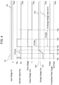
- charger 13 starts the operation of charging electricity storage unit 12 at timing T01.
- the supply of power from contactless power supply unit 25 to contactless power receiver 15 is performed during period PT0102 from timing T01 to timing T02 until storage voltage Vca of electricity storage unit 12 reaches storage voltage value Vc2.
- the operation in which charger 13 charges electricity storage unit 12 is performed from timing T01 to timing T02.
- the operation of charger 13 may be either of a boost-up operation or a stepping-down operation.
- storage voltage Vca increases from timing T01 to timing T02 along a straight trajectory.
- the trajectory of storage voltage Vca changes depending on a coupling status between contactless power supply unit 25 and contactless power receiver 15, or charge characteristics of electricity storage unit 12. Therefore, the trajectory of storage voltage Vca is not necessarily a straight line.
- the supply of power from contactless power supply unit 25 to contactless power receiver 15 is performed continuously even after timing T01. The supply of power, however, may be completed at timing T02.
- operation signal receiver 18 receives operation signal Sop when an operator operates door handle 24 at timing T03.
- discharger 14 starts operation of discharging electricity storage unit 12 at timing T03.
- discharger 14 outputs, to output port 17, power in electricity storage unit 12, which has been charged to cause storage voltage Vca to substantially become storage voltage value Vc2, so as to drive actuator 21.
- actuator 21 is driven by the power in electricity storage unit 12, thereby changing to the unlatched state from the latched state.
- the operation of discharger 14 may be any of a boost-up operation, a stepping-down operation, or an operation of discharging the voltage of electricity storage unit 12 as it is.
- period PT0305 from timing T03 to timing T05 limited power stored in electricity storage unit 12 is output to output port 17 from discharger 14 although no power is supplied to electricity storage unit 12 from automotive battery 19. Accordingly, only discharger 14 is preferably operated during period PT0305 without operating charger 13.
- door latch power supply device 11 places door 22 of vehicle 20 in the unlatched state, thereby enabling the operator to enter vehicle 20 to perform maintenance of vehicle 20.
- Conventional door latch system 1 shown in FIG. 6 includes mechanical latch mechanism 10 as emergency operation mechanism 9. This configuration increases the volume and the weight of the system. The weight of vehicle 8 increases accordingly, and causes fuel consumption of vehicle 8 to deteriorate.
- Door latch power supply device 11 in accordance with the embodiment does not include mechanical latch mechanism 10 which is a redundant function that operates as emergency operation mechanism 9 of conventional door latch system 1. Thus, the weight of vehicle 20 is reduced accordingly.
- door latch power supply system 28 including door latch power supply device 11 and contactless power supply unit 25 which is a power supply located from vehicle 20, power may be supplied to door latch power supply device 11 from another power supply, instead of contactless power supply unit 25.
- Contactless power supply unit 25 may be driven by commercial power or a portable battery. A service of vehicle 20 may possess contactless power supply unit 25. Alternatively, a contactless power supply device for portable communication equipment or the like may be used as contactless power supply unit 25.
- Storage voltage value Vc2 is higher than storage voltage value Vc1.
- storage voltage value Vc1 is set to be lower than a full charge voltage of electricity storage unit 12, i.e., is set to about 50% of the full charge voltage, and is a value at which an influence on the life time is small.
- storage voltage value Vc2 corresponds to an electricity storage amount obtained by storing the power received from contactless power supply unit 25 when the power of automotive battery 19 is insufficient.
- storage voltage value Vc2 is preferably higher than storage voltage value Vc1, i.e., 80% or more of the full charge voltage, or is set as a value of a full charge level.
- Charge indicator 27 is preferably provided in any one of vehicle 20, body 23, door 22, and door latch power supply devices 11.
- Charge indicator 27 indicates an electricity storage completion state when electricity storage unit 12 is charged from contactless power supply unit 25 through contactless power receiver 15 and charger 13 to cause storage voltage Vca of electricity storage unit 12 to reach storage voltage value Vc2, in other words, when the power stored in electricity storage unit 12 reaches a value enough to drive actuator 21.
- Charge indicator 27 allows an operator to visually recognize the charging state of electricity storage unit 12 easily, thereby enabling suitable power supply from contactless power supply unit 25.
- charge indicator 27 may indicate that automotive battery 19 is in an abnormal state. Thus, the operator can visually recognize the state of automotive battery 19 easily.
- door latch power supply device 11 and vehicle 20 have been described in both the case where the input voltage at input port 16 of door latch power supply device 11 is higher than or equal to input threshold Vi1, and the case where the input voltage at input port 16 of door latch power supply device 11 is lower than input threshold Vi1.
- the above-mentioned operation is in an alternative solution divided with reference to a threshold of storage voltage Vca. This operation will be described below.
- discharger 14 When operation signal Sop is received by operation signal receiver 18, discharger 14 outputs power in electricity storage unit 12 to output port 17.
- input voltage Vin is lower than input threshold Vi1 and storage voltage Vca is lower than storage voltage value Vc3
- charger 13 operates using power supplied from contactless power receiver 15 so as to cause storage voltage Vca to become storage voltage value Vc2. After that, when operation signal Sop is received, discharger 14 outputs the power in electricity storage unit 12 to output port 17.
- Storage voltage value Vc3 is set to meet the following condition. Even in the case that input voltage Vin is lower than input threshold Vi1 and the power stored in automotive battery 19 is insufficient, while storage voltage Vca is higher than or equal to storage voltages Vc3 and power remains in electricity storage unit 12, actuator 21 is placed in the unlatched state from the latched state operation signal Sop is received even if electricity storage unit 12 is not charged.
- Storage voltage value Vc3 may be lower than storage voltage value Vc1.
- Storage voltage value Vc3 is determined to be a minimum value that can operate charger 13 and discharger 14, or a minimum value required before a boost-up operation in order to obtain a predetermined voltage in discharger 14 after the boost-up operation.
- charger 13 may be operated when operation signal receiver 18 receives operation signal Sop.
- this state corresponds to the case where input voltage Vin is lower than input threshold Vi1, and cannot start or operate electric device 21A mounted on vehicle 20.
- this state corresponds to the case where input voltage Vin has a value enabling charger 13 and controller 26 to start or operate although input voltage Vin is lower than input threshold Vi1.
- electricity storage unit 12 can be charged so as to cause storage voltage Vca to become storage voltage value Vc2 or storage voltage value Vc3 regardless of the value of storage voltage Vca before charging.
- operation signal Sop When operation signal Sop is received, the power charged in electricity storage unit 12 is discharged, thereby allowing actuator 21 to be placed in the unlatched state in which door 22 is unlatched. Therefore, even when automotive battery 19 is deteriorated to a level disabling electric device 21A to operate, if automotive battery 19 is in a level enabling charger 13 to operate to charge electricity storage unit 12, actuator 21 can be placed in the unlatched state.
- charger 13 When input voltage Vin is lower than the value enabling charger 13, discharger 14, and controller 26 to start or operate, charger 13 is operated to charge electricity storage unit 12 so as to cause the storage voltage of electricity storage unit 12 to become storage voltage value Vc2 using power supplied from contactless power receiver 15, as mentioned above.
- the power supplied from contactless power receiver 15 may be used to energize controller 26, thereby performing to energize controller 26 and charge electricity storage unit 12 simultaneously.
- Door latch power supply device 11 shown in FIG. 1 and FIG. 2 does not necessarily include controller 26.
- charger 13 and discharger 14 are operated based on input voltage Vin, storage voltage Vca, and operation signal Sop.
- FIG. 5 is a block diagram of vehicle 20 including another door latch power supply devices 11a in accordance with the embodiment.
- Door latch power supply device 11a includes controller 26.
- controller 26 detects and determines input voltage Vin and storage voltage Vca, and detects operation signal Sop, and controls operation of charger 13 and discharger 14. Controller 26 is not necessarily arranged integrally as an element or a circuit. Controller 26 may be arranged such that the function thereof is distributed to electricity storage unit 12, charger 13, and discharger 14. Further, power for driving controller 26 is supplied from automotive battery 19 or electricity storage unit 12. Further, when the power stored in automotive battery 19 and electricity storage unit 12 is insufficient, i.e., not enough to drive controller 26, if power is supplied to contactless power receiver 15 from contactless power supply unit 25, the power is used to energize controller 26 and perform the above-mentioned operation.
- charger 13 operates so as to cause storage voltage Vca of electricity storage unit 12 to become storage voltage value Vc1.
- discharger 14 outputs the power in electricity storage unit 12 to output port 17.
- charger 13 operates so as to storage voltage Vca of electricity storage unit 12 to become storage voltage value Vc2 using power supplied from contactless power receiver 15. After that, in response to operation signal Sop received by operation signal receiver 18, discharger 14 outputs the power in electricity storage unit 12 to output port 17.
- door latch power supply device 11 (11a) can easily supply power for driving actuator 21 since door latch power supply device 11 (11a) employs contactless power supply unit 25 to charge electricity storage unit 12 from the outside of vehicle 20, i.e., the outside of door latch power supply device 11 (11a), by contactless power supply.
- door latch power supply device 11 (11a) can drive actuator 21, so that door 22 of vehicle 20 can be placed in the unlatched state. Therefore, an operator can enter vehicle 20 to perform maintenance of vehicle 20. As a result, the mechanical latch mechanism which is a redundant function that operates as an emergency operation mechanism, can be eliminated, thereby reducing the weight of vehicle 20.
- door latch power supply device 11 (11a) is configured to be connected to actuator 21 and an external power supply (automotive battery 19).
- Actuator 21 is configured to provide a latched state in which door 22 is latched and an unlatched state in which door 22 is not latched.
- Door latch power supply device 11 (11a) includes electricity storage unit 12, charger 13 connected to charging path 13A of electricity storage unit 12, discharger 14 connected to discharging path 14A of electricity storage unit 12, contactless power receiver 15 connected to charger 13 and configured to receive power without contact, input port 16 connected to charger 13 and configured to be connected to an external power supply, output port 17 connected to discharger 14, and operation signal receiver 18 configured to receive operation signal Sop sent in response to an operation of opening door 22.
- Input port 16 is configured to be connected to the external power supply.
- Output port 17 is configured to be connected to actuator 21.
- charger 13 operates using power supplied from the external power supply so as to cause storage voltage Vca of electricity storage unit 12 to become storage voltage value Vc1.
- discharger 14 outputs the power in electricity storage unit 12 to output port 17 to place actuator 21 in the unlatched state from the latched state.
- input voltage Vin is lower than input threshold Vi1
- charger 13 operates using power supplied from contactless power receiver 15 so as to cause storage voltage Vca to become storage voltage value Vc2.
- discharger 14 outputs the power in electricity storage unit 12 to output port 17 to place actuator 21 in the unlatched state from the latched state.
- Electricity storage unit 12 includes an electric double layer capacitor.
- Storage voltage value Vc1 is lower than a full charge voltage of the electric double layer capacitor.
- Storage voltage value Vc2 is higher than storage voltage value Vc1.
- charge indicator 27 indicates an electricity storage completion state.
- charger 13 While input voltage Vin is higher than or equal to input threshold Vi1, charger 13 operates in response to an auxiliary signal sent by an operator so as to cause storage voltage Vca of electricity storage unit 12 to become storage voltage value Vc1 using power supplied from the external power supply. While input voltage Vin is lower than input threshold Vi1, charger 13 operates in response to the auxiliary signal so as to cause storage voltage Vca to become storage voltage value Vc2 using power supplied from contactless power receiver 15. Then, in response to operation signal Sop received, discharger 14 outputs the power in electricity storage unit 12 to output port 17 to place actuator 21 in the unlatched state from the latched state.
- charger 13 While input voltage Vin is lower than input threshold Vi1 and storage voltage Vca is lower than storage voltage value Vc3, charger 13 operates using the power supplied from contactless power receiver 15 so as to cause storage voltage Vca to become storage voltage value Vc2. Then, in response to operation signal Sop received, discharger 14 outputs the power in electricity storage unit 12 to output port 17 to place actuator 21 in the unlatched state from the latched state.
- charger 13 While input voltage Vin is lower than input threshold Vi1 and lower than input threshold Vi2, charger 13 operates using the power supplied from contactless power receiver 15 so as to cause storage voltage Vca to become storage voltage value Vc2. Then, in response to operation signal Sop received, discharger 14 outputs the power in electricity storage unit 12 to output port 17 to place actuator 21 in the unlatched state from the latched state.
- a door latch power supply according to the present invention provides an effect of reducing the weight of a vehicle including the door latch power supply, and is useful for various kinds of vehicles.
Landscapes
- Engineering & Computer Science (AREA)
- Power Engineering (AREA)
- Mechanical Engineering (AREA)
- Computer Networks & Wireless Communication (AREA)
- Lock And Its Accessories (AREA)
- Charge And Discharge Circuits For Batteries Or The Like (AREA)
Claims (10)
- Stromversorgungsvorrichtung (11) für einen Türverschluss, die dafür konfiguriert ist, mit einem Stellantrieb (21) und einer externen Stromversorgung (19) verbunden zu werden, wobei der Stellantrieb (21) einen verriegelten Zustand, in dem eine Tür (22) verriegelt ist, und einen entriegelten Zustand, in dem die Tür (22) nicht verriegelt ist, bereitstellt, wobei die Stromversorgungsvorrichtung (11) für einen Türverschluss Folgendes umfasst:eine Stromspeichereinheit (12);eine Ladevorrichtung (13), die mit einem Ladepfad der Stromspeichereinheit (12) verbunden ist;eine Entladevorrichtung (14), die mit einem Entladepfad der Stromspeichereinheit (12) verbunden ist;einen berührungslosen Stromempfänger (15), der mit der Ladevorrichtung (13) verbunden und dafür konfiguriert ist, ohne Kontakt Strom zu empfangen;einen Eingangsanschluss (16), wobei der Eingangsanschluss (16) dafür konfiguriert ist, mit der externen Stromversorgung (19) verbunden zu werden;einen Ausgangsanschluss (17), der mit der Entladevorrichtung (14) verbunden ist, wobei der Ausgangsanschluss (17) dafür konfiguriert ist, mit dem Stellantrieb (21) verbunden zu werden; undeinen Betätigungssignalempfänger (18), der dafür konfiguriert ist, ein Betätigungssignal zu empfangen, das als Reaktion auf eine Betätigung zum Öffnen der Tür (22) gesendet wird, wobeiwährend eine Eingangsspannung, die an dem Eingangsanschluss (16) anliegt, niedriger als ein erster Eingangsschwellenwert ist, die Ladevorrichtung (13) dafür konfiguriert ist, unter Verwendung von Strom, der von dem berührungslosen Stromempfänger (15) zugeführt wird, so zu funktionieren, dass sie bewirkt, dass eine Speicherspannung (Vca) der Stromspeichereinheit (12) zu einem zweiten Speicherspannungswert (Vc2) wird, und dann die Entladevorrichtung (14) dafür konfiguriert ist, in der Stromspeichereinheit (12) gespeicherten Strom an den Ausgangsanschluss (17) auszugeben, um den Stellantrieb (21) als Reaktion auf das von dem Betätigungssignalempfänger (18) empfangene Betätigungssignal in den entriegelten Zustand zu versetzen,dadurch gekennzeichnet, dass der Eingangsanschluss (16) mit der Ladevorrichtung (13) verbunden ist,wobeiwährend die Eingangsspannung, die an dem Eingangsanschluss (16) anliegt, höher als ein erster Eingangsschwellenwert oder gleich diesem ist, die Ladevorrichtung (13) dafür konfiguriert ist, unter Verwendung von Strom, der von der externen Stromversorgung (19) zugeführt wird, so zu funktionieren, dass sie bewirkt, dass die Speicherspannung (Vca) der Stromspeichereinheit (12) zu einem ersten Speicherspannungswert (Vc1) wird, und die Entladevorrichtung (14) dafür konfiguriert ist, in der Stromspeichereinheit (12) gespeicherten Strom an den Ausgangsanschluss (17) auszugeben, um den Stellantrieb (21) als Reaktion auf das von dem Betätigungssignalempfänger (18) empfangene Betätigungssignal in den entriegelten Zustand zu versetzen, undder zweite Speicherspannungswert (Vc2) höher als der erste Speicherspannungswert (Vc1) ist.
- Stromversorgungsvorrichtung für einen Türverschluss nach Anspruch 1, wobeidie Stromspeichereinheit (12) einen elektrischen Doppelschichtkondensator umfasst, undder erste Speicherspannungswert (Vc1) niedriger als eine volle Ladespannung des elektrischen Doppelschichtkondensators ist.
- Stromversorgungsvorrichtung für einen Türverschluss nach Anspruch 1, die ferner eine Ladeanzeige (27) umfasst, die dafür konfiguriert ist, einen Zustand des Abschlusses der Stromspeicherung anzuzeigen, der der Speicherspannung (Vca) entspricht, die durch den von dem berührungslosen Stromempfänger (15) gelieferten Strom auf den zweiten Speicherspannungswert (Vc2) oder mehr erhöht wird.
- Stromversorgungsvorrichtung für einen Türverschluss, die dafür konfiguriert ist, mit einem Stellantrieb (21) und einer externen Stromversorgung (19) verbunden zu werden, wobei der Stellantrieb (21) einen verriegelten Zustand, in dem eine Tür (22) verriegelt ist, und einen entriegelten Zustand, in dem die Tür (22) nicht verriegelt ist, bereitstellt, wobei die Stromversorgungsvorrichtung (11) für einen Türverschluss Folgendes umfasst:eine Stromspeichereinheit (12);eine Ladevorrichtung (13), die mit einem Ladepfad der Stromspeichereinheit (12) verbunden ist;eine Entladevorrichtung (14), die mit einem Entladepfad der Stromspeichereinheit (12) verbunden ist;einen berührungslosen Stromempfänger (15), der mit der Ladevorrichtung (13) verbunden und dafür konfiguriert ist, ohne Kontakt Strom zu empfangen;einen Eingangsanschluss (16), der mit der Ladevorrichtung (13) verbunden ist, wobei der Eingangsanschluss (16) dafür konfiguriert ist, mit der externen Stromversorgung (19) verbunden zu werden;einen Ausgangsanschluss (17), der mit der Entladevorrichtung (14) verbunden ist, wobei der Ausgangsanschluss (17) dafür konfiguriert ist, mit dem Stellantrieb (21) verbunden zu werden; undeinen Betätigungssignalempfänger (18), der dafür konfiguriert ist, ein Betätigungssignal zu empfangen, das als Reaktion auf eine Betätigung zum Öffnen der Tür (22) gesendet wird, wobeiwährend eine Eingangsspannung, die an dem Eingangsanschluss (16) anliegt, höher als ein erster Eingangsschwellenwert oder gleich diesem ist, die Ladevorrichtung (13) dafür konfiguriert ist, unter Verwendung von Strom, der von der externen Stromversorgung (19) zugeführt wird, so zu funktionieren, dass sie bewirkt, dass eine Speicherspannung (Vca) der Stromspeichereinheit (12) zu einem ersten Speicherspannungswert (Vc1) wird, und die Entladevorrichtung (14) dafür konfiguriert ist, in der Stromspeichereinheit (12) gespeicherten Strom an den Ausgangsanschluss (17) auszugeben, um den Stellantrieb (21) als Reaktion auf das von dem Betätigungssignalempfänger (18) empfangene Betätigungssignal in den entriegelten Zustand zu versetzen,während die Eingangsspannung niedriger als der erste Eingangsschwellenwert ist und die Speicherspannung (Vca) höher als ein zweiter Speicherspannungswert (Vc3) oder gleich diesem ist, die Ladevorrichtung (13) dafür konfiguriert ist, nicht zu funktionieren, und die Entladevorrichtung (14) dafür konfiguriert ist, den in der Stromspeichereinheit (12) gespeicherten Strom an den Ausgangsanschluss (17) auszugeben, um den Stellantrieb (21) als Reaktion auf das von dem Betätigungssignalempfänger (18) empfangene Betätigungssignal in den entriegelten Zustand zu versetzen,während die Eingangsspannung niedriger als der erste Eingangsschwellenwert ist und die Speicherspannung (Vca) niedriger als der zweite Speicherspannungswert (Vc3) ist, die Ladevorrichtung (13) dafür konfiguriert ist, unter Verwendung von Strom, der von dem berührungslosen Stromempfänger (15) zugeführt wird, so zu funktionieren, dass sie bewirkt, dass die Speicherspannung (Vca) zu einem dritten Speicherspannungswert (Vc2) wird, und dann die Entladevorrichtung (14) dafür konfiguriert ist, den in der Stromspeichereinheit (12) gespeicherten Strom an den Ausgangsanschluss (17) auszugeben, um den Stellantrieb (21) als Reaktion auf das von dem Betätigungssignalempfänger (18) empfangene Betätigungssignal in den entriegelten Zustand zu versetzen, undder dritte Speicherspannungswert (Vc2) höher als der erste Speicherspannungswert (Vc1) ist.
- Stromversorgungsvorrichtung für einen Türverschluss nach Anspruch 4, wobeidie Stromspeichereinheit (12) einen elektrischen Doppelschichtkondensator umfasst, undder erste Speicherspannungswert (Vc1) niedriger als eine volle Ladespannung des elektrischen Doppelschichtkondensators ist.
- Stromversorgungsvorrichtung für einen Türverschluss nach Anspruch 4, die ferner eine Ladeanzeige (27) umfasst, die dafür konfiguriert ist, einen Zustand des Abschlusses der Stromspeicherung anzuzeigen, der der Speicherspannung (Vca) entspricht, die durch den von dem berührungslosen Stromempfänger (15) gelieferten Strom auf den dritten Speicherspannungswert (Vc2) oder mehr erhöht wird.
- Stromversorgungsvorrichtung für einen Türverschluss nach einem der Ansprüche 4 bis 6,
wobei der zweite Speicherspannungswert (Vc3) niedriger als der erste Speicherspannungswert (Vc1) ist. - Stromversorgungsvorrichtung für einen Türverschluss nach einem der Ansprüche 4 bis 7,
wobei der zweite Speicherspannungswert (Vc3) ein Minimalwert ist, der den Betrieb der Entladevorrichtung (14) ermöglicht. - Stromversorgungssystem für einen Türverschluss, umfassend:die Stromversorgungsvorrichtung (11) für einen Türverschluss nach Anspruch 1 oder 4;eine von der Stromversorgungsvorrichtung (11) für einen Türverschluss unabhängige berührungslose Stromversorgungseinheit (25), wobeidie Stromspeichereinheit (12) von der berührungslosen Stromversorgungseinheit (25) über den berührungslosen Stromempfänger (15) und die Ladevorrichtung (13) mit Strom versorgt wird.
- Fahrzeug umfassend:einen Karosserie (23);eine Fahrzeugbatterie (19), die an der Karosserie (23) montiert ist;eine in der Karosserie (23) vorgesehene Tür (22);einen Türgriff (24), der dafür konfiguriert ist, die Tür (22) zu öffnen;einen Stellantrieb (21), der dafür konfiguriert ist, einen verriegelten Zustand, in dem die Tür (22) verriegelt ist, und einen entriegelten Zustand, in dem die Tür (22) nicht verriegelt ist, bereitzustellen; unddie Stromversorgungsvorrichtung (11) für einen Türverschluss nach Anspruch 1 oder 4,wobei der Eingangsanschluss (16) mit der Fahrzeugbatterie (19) verbunden ist und der Ausgangsanschluss (17) mit dem Stellantrieb (21) verbunden ist.
Applications Claiming Priority (2)
| Application Number | Priority Date | Filing Date | Title |
|---|---|---|---|
| JP2017176778 | 2017-09-14 | ||
| PCT/JP2018/026969 WO2019054046A1 (ja) | 2017-09-14 | 2018-07-18 | ドアラッチ電源装置、ドアラッチ電源システム、およびそれを用いた車両 |
Publications (3)
| Publication Number | Publication Date |
|---|---|
| EP3683099A1 EP3683099A1 (de) | 2020-07-22 |
| EP3683099A4 EP3683099A4 (de) | 2020-07-22 |
| EP3683099B1 true EP3683099B1 (de) | 2024-09-04 |
Family
ID=65723538
Family Applications (1)
| Application Number | Title | Priority Date | Filing Date |
|---|---|---|---|
| EP18855618.7A Active EP3683099B1 (de) | 2017-09-14 | 2018-07-18 | Türverriegelungsstromversorgungsvorrichtung, türverriegelungsstromversorgungssystem und fahrzeug damit |
Country Status (4)
| Country | Link |
|---|---|
| US (1) | US11053714B2 (de) |
| EP (1) | EP3683099B1 (de) |
| JP (1) | JP7113363B2 (de) |
| WO (1) | WO2019054046A1 (de) |
Families Citing this family (6)
| Publication number | Priority date | Publication date | Assignee | Title |
|---|---|---|---|---|
| WO2020232543A1 (en) | 2019-05-23 | 2020-11-26 | Magna Closures Inc. | Latch assembly with hybrid backup energy source |
| JP7368218B2 (ja) * | 2019-12-16 | 2023-10-24 | ニチコン株式会社 | 双方向dc/dcコンバータ回路および蓄電システム |
| DE102020102775A1 (de) * | 2020-02-04 | 2021-08-05 | Brose Fahrzeugteile Se & Co. Kommanditgesellschaft, Bamberg | Steueranordnung für den Betrieb eines Kraftfahrzeugschließsystems |
| TWI732687B (zh) * | 2020-09-22 | 2021-07-01 | 低碳動能開發股份有限公司 | 車用磷酸鋰鐵電池備用電力控制系統及控制方法 |
| TWI745228B (zh) * | 2021-02-01 | 2021-11-01 | 低碳動能開發股份有限公司 | 超級電容模組化供電救援裝置及遠端控制方法 |
| US12416187B2 (en) * | 2021-08-02 | 2025-09-16 | Brose Fahrzeugteile Se & Co. Kommanditgesellschaft, Bamberg | Control arrangement for operating a motor vehicle locking system |
Family Cites Families (10)
| Publication number | Priority date | Publication date | Assignee | Title |
|---|---|---|---|---|
| JP3456779B2 (ja) * | 1995-01-10 | 2003-10-14 | 本田技研工業株式会社 | 車両用開閉体の解錠システム |
| JP2007032140A (ja) | 2005-07-28 | 2007-02-08 | Aisin Seiki Co Ltd | ドアロック制御装置 |
| GB0612879D0 (en) | 2006-06-29 | 2006-08-09 | Meritor Technology Inc | Electrical circuit arrangement |
| US8534101B2 (en) * | 2010-02-22 | 2013-09-17 | GM Global Technology Operations LLC | Electronic unlatch system for vehicle door |
| JP5539094B2 (ja) | 2010-08-02 | 2014-07-02 | 三菱電機株式会社 | 非常用電源装置 |
| WO2014156016A1 (ja) | 2013-03-29 | 2014-10-02 | パナソニック株式会社 | ドアラッチ装置とそれを搭載した移動体 |
| JP2015140639A (ja) | 2014-01-30 | 2015-08-03 | 本田技研工業株式会社 | 電子キーシステム |
| US9909344B2 (en) * | 2014-08-26 | 2018-03-06 | Ford Global Technologies, Llc | Keyless vehicle door latch system with powered backup unlock feature |
| US9518408B1 (en) * | 2015-05-21 | 2016-12-13 | Ford Global Technologies, Llc | Alternate backup entry for vehicles |
| CN107016752A (zh) * | 2015-09-29 | 2017-08-04 | 法拉第未来公司 | 电动门释放系统 |
-
2018
- 2018-07-18 EP EP18855618.7A patent/EP3683099B1/de active Active
- 2018-07-18 WO PCT/JP2018/026969 patent/WO2019054046A1/ja not_active Ceased
- 2018-07-18 JP JP2019541933A patent/JP7113363B2/ja active Active
- 2018-07-18 US US16/635,028 patent/US11053714B2/en active Active
Also Published As
| Publication number | Publication date |
|---|---|
| JPWO2019054046A1 (ja) | 2020-12-03 |
| US20200263460A1 (en) | 2020-08-20 |
| EP3683099A1 (de) | 2020-07-22 |
| EP3683099A4 (de) | 2020-07-22 |
| WO2019054046A1 (ja) | 2019-03-21 |
| US11053714B2 (en) | 2021-07-06 |
| JP7113363B2 (ja) | 2022-08-05 |
Similar Documents
| Publication | Publication Date | Title |
|---|---|---|
| EP3683099B1 (de) | Türverriegelungsstromversorgungsvorrichtung, türverriegelungsstromversorgungssystem und fahrzeug damit | |
| EP3528360B1 (de) | Stromversorgungssystem | |
| EP3048693B1 (de) | Anomaliendetektor in einem mosfet-schaltelement und verfahren zur erkennung von anomalien | |
| US9387763B2 (en) | Power source device for vehicle | |
| US10480222B2 (en) | Door latching device and moving body mounted with same | |
| CN108725423B (zh) | 电动车辆的控制装置 | |
| JP6230612B2 (ja) | 車載用蓄電装置 | |
| US9789771B2 (en) | Single battery architecture for electrification vehicle | |
| US8258651B2 (en) | Methods and circuits for controlling a battery disconnect switch | |
| CN109941106A (zh) | 电动车辆的电源系统 | |
| JP2021114869A (ja) | 電源システム | |
| JP6767636B2 (ja) | 電源装置および電源装置を搭載した車両 | |
| JP6528129B2 (ja) | バックアップ電源装置およびバックアップ電源装置を用いた車両 | |
| JP2015077036A (ja) | 車両の電源システム、及び電源ユニット | |
| CN105849997B (zh) | 电源控制装置和电源控制方法 | |
| EP3473481B1 (de) | Brennstoffzellenfahrzeug | |
| US20210309115A1 (en) | Method for operating at least one electrical component of a vehicle | |
| US11962183B2 (en) | Backup power system | |
| JP2018129936A (ja) | 電源システム | |
| EP4365393B1 (de) | Elektronisch gesteuerter türriegel | |
| US20250170913A1 (en) | Vehicle charging apparatus, vehicle charging control method, and vehicle charging system | |
| CN116945966A (zh) | 车辆启动装置、方法及车辆 | |
| KR20180112484A (ko) | 리던던트 배터리가 포함된 배터리 관리 장치 및 방법 | |
| JP2017056853A (ja) | 車両用電源制御装置、車両用電源制御装置の制御方法 |
Legal Events
| Date | Code | Title | Description |
|---|---|---|---|
| STAA | Information on the status of an ep patent application or granted ep patent |
Free format text: STATUS: THE INTERNATIONAL PUBLICATION HAS BEEN MADE |
|
| PUAI | Public reference made under article 153(3) epc to a published international application that has entered the european phase |
Free format text: ORIGINAL CODE: 0009012 |
|
| STAA | Information on the status of an ep patent application or granted ep patent |
Free format text: STATUS: REQUEST FOR EXAMINATION WAS MADE |
|
| 17P | Request for examination filed |
Effective date: 20200227 |
|
| A4 | Supplementary search report drawn up and despatched |
Effective date: 20200612 |
|
| AK | Designated contracting states |
Kind code of ref document: A1 Designated state(s): AL AT BE BG CH CY CZ DE DK EE ES FI FR GB GR HR HU IE IS IT LI LT LU LV MC MK MT NL NO PL PT RO RS SE SI SK SM TR |
|
| AX | Request for extension of the european patent |
Extension state: BA ME |
|
| DAV | Request for validation of the european patent (deleted) | ||
| DAX | Request for extension of the european patent (deleted) | ||
| STAA | Information on the status of an ep patent application or granted ep patent |
Free format text: STATUS: EXAMINATION IS IN PROGRESS |
|
| 17Q | First examination report despatched |
Effective date: 20220303 |
|
| GRAP | Despatch of communication of intention to grant a patent |
Free format text: ORIGINAL CODE: EPIDOSNIGR1 |
|
| STAA | Information on the status of an ep patent application or granted ep patent |
Free format text: STATUS: GRANT OF PATENT IS INTENDED |
|
| RIC1 | Information provided on ipc code assigned before grant |
Ipc: H02J 50/00 20160101ALN20240122BHEP Ipc: E05B 81/88 20140101ALI20240122BHEP Ipc: E05B 81/86 20140101ALI20240122BHEP Ipc: E05B 81/76 20140101ALI20240122BHEP Ipc: E05B 81/04 20140101ALI20240122BHEP Ipc: H02J 7/34 20060101ALI20240122BHEP Ipc: H02J 7/00 20060101ALI20240122BHEP Ipc: E05B 81/80 20140101ALI20240122BHEP Ipc: E05B 49/00 20060101ALI20240122BHEP Ipc: B60R 25/40 20130101ALI20240122BHEP Ipc: B60R 16/03 20060101AFI20240122BHEP |
|
| INTG | Intention to grant announced |
Effective date: 20240222 |
|
| GRAS | Grant fee paid |
Free format text: ORIGINAL CODE: EPIDOSNIGR3 |
|
| GRAA | (expected) grant |
Free format text: ORIGINAL CODE: 0009210 |
|
| STAA | Information on the status of an ep patent application or granted ep patent |
Free format text: STATUS: THE PATENT HAS BEEN GRANTED |
|
| AK | Designated contracting states |
Kind code of ref document: B1 Designated state(s): AL AT BE BG CH CY CZ DE DK EE ES FI FR GB GR HR HU IE IS IT LI LT LU LV MC MK MT NL NO PL PT RO RS SE SI SK SM TR |
|
| REG | Reference to a national code |
Ref country code: GB Ref legal event code: FG4D |
|
| REG | Reference to a national code |
Ref country code: CH Ref legal event code: EP |
|
| REG | Reference to a national code |
Ref country code: IE Ref legal event code: FG4D |
|
| REG | Reference to a national code |
Ref country code: DE Ref legal event code: R096 Ref document number: 602018074093 Country of ref document: DE |
|
| REG | Reference to a national code |
Ref country code: LT Ref legal event code: MG9D |
|
| REG | Reference to a national code |
Ref country code: NL Ref legal event code: MP Effective date: 20240904 |
|
| PG25 | Lapsed in a contracting state [announced via postgrant information from national office to epo] |
Ref country code: NO Free format text: LAPSE BECAUSE OF FAILURE TO SUBMIT A TRANSLATION OF THE DESCRIPTION OR TO PAY THE FEE WITHIN THE PRESCRIBED TIME-LIMIT Effective date: 20241204 |
|
| PG25 | Lapsed in a contracting state [announced via postgrant information from national office to epo] |
Ref country code: PL Free format text: LAPSE BECAUSE OF FAILURE TO SUBMIT A TRANSLATION OF THE DESCRIPTION OR TO PAY THE FEE WITHIN THE PRESCRIBED TIME-LIMIT Effective date: 20240904 Ref country code: GR Free format text: LAPSE BECAUSE OF FAILURE TO SUBMIT A TRANSLATION OF THE DESCRIPTION OR TO PAY THE FEE WITHIN THE PRESCRIBED TIME-LIMIT Effective date: 20241205 Ref country code: FI Free format text: LAPSE BECAUSE OF FAILURE TO SUBMIT A TRANSLATION OF THE DESCRIPTION OR TO PAY THE FEE WITHIN THE PRESCRIBED TIME-LIMIT Effective date: 20240904 |
|
| PG25 | Lapsed in a contracting state [announced via postgrant information from national office to epo] |
Ref country code: BG Free format text: LAPSE BECAUSE OF FAILURE TO SUBMIT A TRANSLATION OF THE DESCRIPTION OR TO PAY THE FEE WITHIN THE PRESCRIBED TIME-LIMIT Effective date: 20240904 |
|
| PG25 | Lapsed in a contracting state [announced via postgrant information from national office to epo] |
Ref country code: LV Free format text: LAPSE BECAUSE OF FAILURE TO SUBMIT A TRANSLATION OF THE DESCRIPTION OR TO PAY THE FEE WITHIN THE PRESCRIBED TIME-LIMIT Effective date: 20240904 |
|
| PG25 | Lapsed in a contracting state [announced via postgrant information from national office to epo] |
Ref country code: HR Free format text: LAPSE BECAUSE OF FAILURE TO SUBMIT A TRANSLATION OF THE DESCRIPTION OR TO PAY THE FEE WITHIN THE PRESCRIBED TIME-LIMIT Effective date: 20240904 |
|
| PG25 | Lapsed in a contracting state [announced via postgrant information from national office to epo] |
Ref country code: ES Free format text: LAPSE BECAUSE OF FAILURE TO SUBMIT A TRANSLATION OF THE DESCRIPTION OR TO PAY THE FEE WITHIN THE PRESCRIBED TIME-LIMIT Effective date: 20240904 Ref country code: RS Free format text: LAPSE BECAUSE OF FAILURE TO SUBMIT A TRANSLATION OF THE DESCRIPTION OR TO PAY THE FEE WITHIN THE PRESCRIBED TIME-LIMIT Effective date: 20241204 |
|
| PG25 | Lapsed in a contracting state [announced via postgrant information from national office to epo] |
Ref country code: RS Free format text: LAPSE BECAUSE OF FAILURE TO SUBMIT A TRANSLATION OF THE DESCRIPTION OR TO PAY THE FEE WITHIN THE PRESCRIBED TIME-LIMIT Effective date: 20241204 Ref country code: PL Free format text: LAPSE BECAUSE OF FAILURE TO SUBMIT A TRANSLATION OF THE DESCRIPTION OR TO PAY THE FEE WITHIN THE PRESCRIBED TIME-LIMIT Effective date: 20240904 Ref country code: NO Free format text: LAPSE BECAUSE OF FAILURE TO SUBMIT A TRANSLATION OF THE DESCRIPTION OR TO PAY THE FEE WITHIN THE PRESCRIBED TIME-LIMIT Effective date: 20241204 Ref country code: LV Free format text: LAPSE BECAUSE OF FAILURE TO SUBMIT A TRANSLATION OF THE DESCRIPTION OR TO PAY THE FEE WITHIN THE PRESCRIBED TIME-LIMIT Effective date: 20240904 Ref country code: HR Free format text: LAPSE BECAUSE OF FAILURE TO SUBMIT A TRANSLATION OF THE DESCRIPTION OR TO PAY THE FEE WITHIN THE PRESCRIBED TIME-LIMIT Effective date: 20240904 Ref country code: GR Free format text: LAPSE BECAUSE OF FAILURE TO SUBMIT A TRANSLATION OF THE DESCRIPTION OR TO PAY THE FEE WITHIN THE PRESCRIBED TIME-LIMIT Effective date: 20241205 Ref country code: FI Free format text: LAPSE BECAUSE OF FAILURE TO SUBMIT A TRANSLATION OF THE DESCRIPTION OR TO PAY THE FEE WITHIN THE PRESCRIBED TIME-LIMIT Effective date: 20240904 Ref country code: ES Free format text: LAPSE BECAUSE OF FAILURE TO SUBMIT A TRANSLATION OF THE DESCRIPTION OR TO PAY THE FEE WITHIN THE PRESCRIBED TIME-LIMIT Effective date: 20240904 Ref country code: BG Free format text: LAPSE BECAUSE OF FAILURE TO SUBMIT A TRANSLATION OF THE DESCRIPTION OR TO PAY THE FEE WITHIN THE PRESCRIBED TIME-LIMIT Effective date: 20240904 |
|
| REG | Reference to a national code |
Ref country code: AT Ref legal event code: MK05 Ref document number: 1720062 Country of ref document: AT Kind code of ref document: T Effective date: 20240904 |
|
| PG25 | Lapsed in a contracting state [announced via postgrant information from national office to epo] |
Ref country code: NL Free format text: LAPSE BECAUSE OF FAILURE TO SUBMIT A TRANSLATION OF THE DESCRIPTION OR TO PAY THE FEE WITHIN THE PRESCRIBED TIME-LIMIT Effective date: 20240904 |
|
| PG25 | Lapsed in a contracting state [announced via postgrant information from national office to epo] |
Ref country code: PT Free format text: LAPSE BECAUSE OF FAILURE TO SUBMIT A TRANSLATION OF THE DESCRIPTION OR TO PAY THE FEE WITHIN THE PRESCRIBED TIME-LIMIT Effective date: 20250106 Ref country code: IS Free format text: LAPSE BECAUSE OF FAILURE TO SUBMIT A TRANSLATION OF THE DESCRIPTION OR TO PAY THE FEE WITHIN THE PRESCRIBED TIME-LIMIT Effective date: 20250104 |
|
| PG25 | Lapsed in a contracting state [announced via postgrant information from national office to epo] |
Ref country code: SM Free format text: LAPSE BECAUSE OF FAILURE TO SUBMIT A TRANSLATION OF THE DESCRIPTION OR TO PAY THE FEE WITHIN THE PRESCRIBED TIME-LIMIT Effective date: 20240904 Ref country code: RO Free format text: LAPSE BECAUSE OF FAILURE TO SUBMIT A TRANSLATION OF THE DESCRIPTION OR TO PAY THE FEE WITHIN THE PRESCRIBED TIME-LIMIT Effective date: 20240904 |
|
| PG25 | Lapsed in a contracting state [announced via postgrant information from national office to epo] |
Ref country code: AT Free format text: LAPSE BECAUSE OF FAILURE TO SUBMIT A TRANSLATION OF THE DESCRIPTION OR TO PAY THE FEE WITHIN THE PRESCRIBED TIME-LIMIT Effective date: 20240904 Ref country code: EE Free format text: LAPSE BECAUSE OF FAILURE TO SUBMIT A TRANSLATION OF THE DESCRIPTION OR TO PAY THE FEE WITHIN THE PRESCRIBED TIME-LIMIT Effective date: 20240904 |
|
| PG25 | Lapsed in a contracting state [announced via postgrant information from national office to epo] |
Ref country code: CZ Free format text: LAPSE BECAUSE OF FAILURE TO SUBMIT A TRANSLATION OF THE DESCRIPTION OR TO PAY THE FEE WITHIN THE PRESCRIBED TIME-LIMIT Effective date: 20240904 |
|
| PG25 | Lapsed in a contracting state [announced via postgrant information from national office to epo] |
Ref country code: SK Free format text: LAPSE BECAUSE OF FAILURE TO SUBMIT A TRANSLATION OF THE DESCRIPTION OR TO PAY THE FEE WITHIN THE PRESCRIBED TIME-LIMIT Effective date: 20240904 Ref country code: IT Free format text: LAPSE BECAUSE OF FAILURE TO SUBMIT A TRANSLATION OF THE DESCRIPTION OR TO PAY THE FEE WITHIN THE PRESCRIBED TIME-LIMIT Effective date: 20240904 |
|
| REG | Reference to a national code |
Ref country code: DE Ref legal event code: R097 Ref document number: 602018074093 Country of ref document: DE |
|
| PG25 | Lapsed in a contracting state [announced via postgrant information from national office to epo] |
Ref country code: DK Free format text: LAPSE BECAUSE OF FAILURE TO SUBMIT A TRANSLATION OF THE DESCRIPTION OR TO PAY THE FEE WITHIN THE PRESCRIBED TIME-LIMIT Effective date: 20240904 |
|
| PLBE | No opposition filed within time limit |
Free format text: ORIGINAL CODE: 0009261 |
|
| STAA | Information on the status of an ep patent application or granted ep patent |
Free format text: STATUS: NO OPPOSITION FILED WITHIN TIME LIMIT |
|
| 26N | No opposition filed |
Effective date: 20250605 |
|
| PG25 | Lapsed in a contracting state [announced via postgrant information from national office to epo] |
Ref country code: SE Free format text: LAPSE BECAUSE OF FAILURE TO SUBMIT A TRANSLATION OF THE DESCRIPTION OR TO PAY THE FEE WITHIN THE PRESCRIBED TIME-LIMIT Effective date: 20240904 |
|
| PGFP | Annual fee paid to national office [announced via postgrant information from national office to epo] |
Ref country code: DE Payment date: 20250722 Year of fee payment: 8 |