EP3682957B1 - Rad-abziehwerkzeug für ein spielfahrzeug-rad - Google Patents
Rad-abziehwerkzeug für ein spielfahrzeug-rad Download PDFInfo
- Publication number
- EP3682957B1 EP3682957B1 EP19213039.1A EP19213039A EP3682957B1 EP 3682957 B1 EP3682957 B1 EP 3682957B1 EP 19213039 A EP19213039 A EP 19213039A EP 3682957 B1 EP3682957 B1 EP 3682957B1
- Authority
- EP
- European Patent Office
- Prior art keywords
- wheel
- removal
- toy vehicle
- tool
- lever
- Prior art date
- Legal status (The legal status is an assumption and is not a legal conclusion. Google has not performed a legal analysis and makes no representation as to the accuracy of the status listed.)
- Active
Links
Images




Classifications
-
- A—HUMAN NECESSITIES
- A63—SPORTS; GAMES; AMUSEMENTS
- A63H—TOYS, e.g. TOPS, DOLLS, HOOPS OR BUILDING BLOCKS
- A63H17/00—Toy vehicles, e.g. with self-drive; ; Cranes, winches or the like; Accessories therefor
- A63H17/26—Details; Accessories
- A63H17/262—Chassis; Wheel mountings; Wheels; Axles; Suspensions; Fitting body portions to chassis
-
- A—HUMAN NECESSITIES
- A63—SPORTS; GAMES; AMUSEMENTS
- A63H—TOYS, e.g. TOPS, DOLLS, HOOPS OR BUILDING BLOCKS
- A63H17/00—Toy vehicles, e.g. with self-drive; ; Cranes, winches or the like; Accessories therefor
- A63H17/002—Toy vehicles, e.g. with self-drive; ; Cranes, winches or the like; Accessories therefor made of parts to be assembled
Definitions
- the invention relates to a wheel puller for a toy vehicle wheel.
- the DE 33 02 826 A1 discloses a toy vehicle with stub axles with a slot and undercut, into each of which a wheel is pressed, and a puller for this.
- the DE 33 47 791 A1 discloses an apparatus for dismantling and dismantling a toy wheel.
- the EP 3 192 575 A1 discloses a rotator assembly for a toy.
- the DE 1 730 029 U discloses an assembly toy having means for changing wheels.
- the wheels are often connected to the chassis-side vehicle components by pushing them with a press fit.
- detaching the wheel from the chassis-side vehicle component is sometimes difficult and, if the wheel is simply removed manually, it is not based on the real model as desired.
- the wheel is removed from the vehicle component on the chassis side via a lever action of a removal lever solved, which is an integral part of the wheel puller.
- a removal lever solved which is an integral part of the wheel puller.
- the wheel pulling tool can be made of plastic.
- the wheel pulling tool can be manufactured as an injection-molded component.
- the wheel pulling tool can consist of exactly two components that are movably connected to one another, namely the tool body and the pulling lever.
- a pull-off force can be specified over a length of an actuating section of the pull-off lever.
- rear grip sections according to claim 2 have proven to be useful for safely pulling off the toy vehicle wheel.
- the wheel pulling tool can have two to, for example, eight rear grip sections, e.g. five rear grip sections.
- the number of rear grip sections can be adapted to a rim design of the toy vehicle wheel.
- a distributed arrangement of the rear grip sections according to claim 3 leads to a uniform introduction of force from the wheel pulling tool to the toy vehicle wheel during pulling.
- the rear grip sections viewed in a projection perpendicular to the pull-off direction, can be arranged in a statically stable manner around the support section. As seen in this projection, the grip-behind sections can be arranged uniformly distributed around the support section or also distributed irregularly around the support section.
- a design of the pull-off lever according to claim 5 is structurally simple.
- a design of the wheel pulling tool according to claim 7 is kinematically favorable.
- a counter-support face which according to claim 9 is used as a chassis-side vehicle component to support the pull-off lever, represents a variant that is structurally easy to implement.
- the components of the toy vehicle set in particular a wheel assembly of the toy vehicle, can be made entirely of plastic. These plastic components can be manufactured as injection molded components.
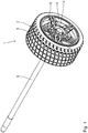
- the wheel assembly 1 shown has a toy vehicle wheel 2 for a toy vehicle (otherwise not shown).
- the wheel 2 has a tire 3, a rim 4 and a disc brake component 5 (cf. in particular the Fig. 2 ).
- the wheel assembly 1 also includes an axle 6 extending between a pair of wheels of the toy vehicle.
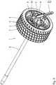
- a wheel pulling tool 7 is used to pull the wheel 2 off the associated free end of the axle 6 (cf., for example Fig. 2 ).
- the wheel pulling tool 7 has a tool base body 8, on which a total of five rear grip sections 9 are each molded in one piece. Each of the rear engagement sections 9 is assigned to engage behind one Pull-off section 10 of the wheel 2, namely designed to grip behind one of the five spokes of the rim 4. The rear grip sections 9 are firmly connected to the tool base body 8.
- the wheel pulling tool 7 also has a pulling lever 11.
- the latter has (see. For example Fig. 5 ) a support section 12 at a free end of the lever and an actuation section 13 at the other free end of the lever.
- the support section 12 serves to support the pull-off lever 11 on a chassis-side vehicle component, namely on a counter-support face 14 of the wheel assembly 1.
- the counter-support face 14 is part of the disc brake component 5. Alternatively, it can also be used as a counter-support face 14 For example, an end face of the axis 6 can be used.
- the trigger lever 11 is about a trigger pivot axis 15 (see. Eg Fig. 4, 5 and 10 ) pivotally mounted on the tool body 8 of the wheel puller 7.
- the rear grip sections 9 are arranged in a rear grip plane 16, which is used as the sectional plane of the Fig. 9 is selected.
- the trigger pivot axis 15 runs parallel to the rear grip plane 16.
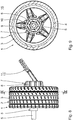
- FIGS. 3 to 5 show the wheel puller 7 relative to the rim 4 in a tool insertion position in which the rear grip sections 9 do not engage behind the puller sections 10, so that the axial insertion of the rear grip sections 9 between the spokes of the rim 4 is made possible.
- FIGS. 6 to 9 show the wheel removal tool 7 relative to the rim 4 of the wheel assembly 1 in a removal starting position in which the rear grip sections 9 reach behind the pull-off sections 10 of the wheel 2.
- the support section 12 of the extraction lever 11 rests against the counter-supporting end face 14 of the wheel 2.
- the wheel extraction tool 7 is displaced in the starting extraction position clockwise by approximately 10 ° to 20 ° about the axis 6.
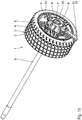
- Fig. 10 and 11 show the wheel removal tool 7 in the removal end position.
- the rear grip sections 9 are displaced relative to the support section 12 in a removal direction 17, that is to say away from the free end of the axle 6. Because the rear grip sections 9 reach behind the pulling sections 10 of the wheel 2, the wheel pulling tool 7 takes the wheel 2 with it when it moves from the pulling-off starting position to the pulling-off end position, so that the wheel 2 is axially removed from the disc brake component 5 and in particular comes free from the axis 6.
- the rear grip sections 9 are (cf. Fig. 9 ), seen in a projection perpendicular to the pulling direction 17, evenly distributed around the support section 12.
- the pulling direction 17 runs in the direction of the axis 6.
- the actuating section 13 When the wheel pulling tool 7 is transferred from the starting pulling position to the end pulling position, the actuating section 13 is pressed down in the direction of the rim 4 of the wheel 2 and the support section 12 exerts a supporting force on the counter support face 14, which is via the pivot bearing of the pull-off lever 11 on the base body 8 and the rear grip sections 9 is transmitted as a pull-off force to the pull-off sections 10 of the rim 4.
- the wheel assembly 1 is made entirely of plastic.
- the components of the wheel assembly 1 are designed as injection molded components.
- the wheel puller 7 is made of plastic.
- the components of the wheel extraction tool 7, namely the base body 8 and the extraction lever 11, are each an injection molded component.
Landscapes
- Toys (AREA)
Description
- Die vorliegende Patentanmeldung nimmt die Priorität der deutschen Patentanmeldung
DE 10 2019 200 392.3 in Anspruch, deren Inhalt durch Bezugnahme hierin aufgenommen wird. - Die Erfindung betrifft ein Rad-Abziehwerkzeug für ein Spielfahrzeug-Rad.
- Die
DE 33 02 826 A1 offenbart ein Spielfahrzeug mit Achsstummeln mit Schlitz und Hinterschneidung, in die jeweils ein Rad eingedrückt wird sowie eine Abziehvorrichtung hierfür. DieDE 33 47 791 A1 offenbart eine Vorrichtung zum Ab- und Anmontieren eines Spielzeugrades. DieEP 3 192 575 A1 offenbart eine Dreheinrichtungs-Baugruppe für ein Spielzeug. DieDE 1 730 029 U offenbart ein Montagespielzeug mit einer Einrichtung zum Laufradwechsel. - Bei Spielfahrzeugen werden Räder mit fahrwerksseitigen Fahrzeugkomponenten oft durch Aufstecken unter Presspassung verbunden. Insbesondere, wenn ein Räderwechsel gespielt werden soll, gestaltet sich das Lösen des Rades von der fahrwerksseitigen Fahrzeugkomponente mitunter als schwierig und ist zudem, wenn das Rad schlicht manuell abgezogen wird, nicht wie gewünscht orientiert am realen Vorbild.
- Es ist daher eine Aufgabe der vorliegenden Erfindung, ein einfaches und insbesondere realitätsnahes Lösen eines Spielfahrzeug-Rades von einer fahrwerksseitigen Fahrzeugkomponente zu ermöglichen.
- Diese Aufgabe ist erfindungsgemäß gelöst durch ein Rad-Abziehwerkzeug mit den im Anspruch 1 angegebenen Merkmalen.
- Mit dem erfindungsgemäßen Rad-Abziehwerkzeug wird das Rad von der fahrwerksseitigen Fahrzeugkomponente über eine Hebelwirkung eines Abzieh-Hebels gelöst, der ein integraler Bestandteil des Rad-Abziehwerkzeuges ist. Es ergibt sich ein einfaches Lösen auch eines fester sitzenden Spielfahrzeug-Rades, welches durch Verwendung eines Werkzeuges zudem näher am realen Vorbild orientiert ist. Das Rad-Abziehwerkzeug kann aus Kunststoff gefertigt sein. Das Rad-Abziehwerkzeug kann als Spritzguss-Bauteil gefertigt sein. Das Rad-Abziehwerkzeug kann aus exakt zwei miteinander beweglich verbundenen Komponenten bestehen, nämlich dem Werkzeug-Grundkörper und dem Abzieh-Hebel. Eine Abzugskraft kann über eine Länge eines Betätigungsabschnitts des Abzieh-Hebels vorgegeben werden.
- Mehrere Hintergriffs-Abschnitte nach Anspruch 2 haben sich zum sicheren Abziehen des Spielfahrzeug-Rades bewährt. Das Rad-Abziehwerkzeug kann zwei bis beispielsweise acht Hintergriffs-Abschnitte, z.B. fünf Hintergriffs-Abschnitte, aufweisen. Die Anzahl der Hintergriffs-Abschnitte kann an ein Felgendesign des Spielfahrzeug-Rades angepasst sein.
- Eine verteilte Anordnung der Hintergriffs-Abschnitte nach Anspruch 3 führt zu einer gleichmäßigen Krafteinleitung vom Rad-Abziehwerkzeug auf das Spielfahrzeug-Rad beim Abziehen. Die Hintergriffs-Abschnitte können, gesehen in Projektion senkrecht zur Abziehrichtung, statisch stabil verteilt um den Abstützabschnitt angeordnet sein. Die Hintergriffs-Abschnitte können, gesehen in dieser Projektion, gleichverteilt um den Abstützabschnitt oder auch unregelmäßig verteilt um den Abstützabschnitt angeordnet sein.
- Bei einem Hintergriff in Umfangsrichtung nach Anspruch 4 ist eine Schwenkverlagerung des Rad-Abziehwerkzeugs zwischen einer Werkzeug-Einführstellung, in der der mindestens eine Hintergriffs-Abschnitt noch außer Eingriff mit dem zugeordneten Abzieh-Abschnitt des Spielfahrzeug-Rades ist, und der Abzieh-Ausgangsstellung möglich, in der der mindestens eine Hintergriffs-Abschnitt den zugeordneten Abzieh-Abschnitt des Spielfahrzeug-Rades hintergreift. Dies ermöglicht eine gleichzeitig einfache Gestaltung des Rad-Abziehwerkzeuges und auch eine einfache Bedienung des Rad-Abziehwerkzeuges.
- Eine Gestaltung des Abzieh-Hebels nach Anspruch 5 ist konstruktiv einfach.
- Entsprechendes gilt für eine schwenkbare Gestaltung des Abzieh-Hebels nach Anspruch 6.
- Eine Gestaltung des Rad-Abziehwerkzeuges nach Anspruch 7 ist kinematisch günstig.
- Die Vorteile eines Spielfahrzeug-Sets nach Anspruch 8 entsprechen denen, die vorstehend unter Bezugnahme auf das Rad-Abziehwerkzeug bereits erläutert wurden.
- Eine Gegenabstütz-Stirnfläche, die nach Anspruch 9 als fahrwerksseitige Fahrzeugkomponente zum Abstützen des Abzieh-Hebels genutzt wird, stellt eine konstruktiv einfach zu realisierende Variante dar.
- Die Komponenten des Spielfahrzeug-Sets, insbesondere eine Rad-Baugruppe des Spielfahrzeugs, können insgesamt aus Kunststoff gefertigt sein. Diese Kunststoffkomponenten können als Spritzguss-Bauteile gefertigt sein.
- Ein Ausführungsbeispiel der Erfindung wird nachfolgend anhand der Zeichnungen näher erläutert. In dieser Zeichnung zeigen:
- Fig. 1
- perspektivisch eine Rad-Baugruppe eines Spielfahrzeuges mit einem Spielfahrzeug-Rad und einer zwischen einem Räderpaar des Spielfahrzeugs durchgehenden Achse;
- Fig. 2
- eine Explosionsdarstellung der Rad-Baugruppe nach
Fig. 1 , wobei zusätzlich eine Scheibenbremsen-Komponente der Rad-Baugruppe sichtbar ist und ebenfalls zusätzlich ein Rad-Abziehwerkzeug für das Rad dargestellt ist; - Fig. 3
- die Rad-Baugruppe mit dem Rad-Abziehwerkzeug in einer Werkzeug-Einführstellung;
- Fig. 4
- eine Aufsicht auf die Rad-Baugruppe mit dem Rad-Abziehwerkzeug in der Werkzeug-Einführstellung;
- Fig. 5
- einen Schnitt gemäß Linie V-V in
Fig. 4 ; - Fig. 6
- in einer zu
Fig. 3 ähnlichen Stellung die Rad-Baugruppe mit dem Rad-Abziehwerkzeug in einer Abzieh-Ausgangsstellung, die im Vergleich zur Werkzeug-Einführstellung nachFig. 3 im Uhrzeigersinn relativ zum Rad verschwenkt ist; - Fig. 7
- einen Axialschnitt durch die Rad-Baugruppe mit dem Rad-Abziehwerkzeug in der Abzieh-Ausgangsstellung;
- Fig. 8
- eine Seitenansicht der Rad-Baugruppe mit dem Rad-Abziehwerkzeug in der Abzieh-Ausgangsstellung;
- Fig. 9
- einen Schnitt gemäß Linie IX-IX in
Fig. 8 ; - Fig. 10
- in einer zu
Fig. 3 ähnlichen Ansicht die Rad-Baugruppe mit dem Rad-Abziehwerkzeug in einer Abzieh-Endstellung; und - Fig. 11
- die Rad-Baugruppe mit dem Rad-Abziehwerkzeug in der Abzieh-Endstellung, insgesamt in einem Axialschnitt.
- Eine in der
Fig. 1 dargestellte Rad-Baugruppe 1 hat ein Spielfahrzeug-Rad 2 für ein ansonsten nicht dargestelltes Spielfahrzeug. Das Rad 2 hat einen Reifen 3, eine Felge 4 und eine Scheibenbremsen-Komponente 5 (vgl. insbesondere dieFig. 2 ). Zur Rad-Baugruppe 1 gehört weiterhin eine zwischen einem Räderpaar des Spielfahrzeugs durchgehende Achse 6. - Dem Axialschnitt nach
Fig. 5 ist zu entnehmen, dass die Scheibenbremsen-Komponente 5 endseitig unter Presspassung auf die Achse 6 aufgesteckt ist, wobei wiederum die Felge 4 des Rades 2 auf einen achsenseitigen Endabschnitt der Scheibenbremsen-Komponente 5 unter Presspassung aufgesteckt ist. - Zum Abziehen des Rades 2 vom zugehörigen freien Ende der Achse 6 dient ein Rad-Abziehwerkzeug 7 (vgl. z.B.
Fig. 2 ). - Das Rad-Abziehwerkzeug 7 hat einen Werkzeug-Grundkörper 8, an den insgesamt fünf Hintergriffs-Abschnitte 9 jeweils einstückig angeformt sind. Jeder der Hintergriffs-Abschnitte 9 ist zum Hintergreifen eines zugeordneten Abzieh-Abschnitts 10 des Rades 2, nämlich zum Hintergreifen jeweils einer der fünf Speichen der Felge 4 ausgebildet. Die Hintergriffs-Abschnitte 9 sind fest mit dem Werkzeug-Grundkörper 8 verbunden.
- Das Rad-Abziehwerkzeug 7 hat weiterhin einen Abzieh-Hebel 11. Letzterer hat (vgl. z.B.
Fig. 5 ) einen Abstützabschnitt 12 an einem freien Hebelende und einen Betätigungsabschnitt 13 am anderen freien Hebelende. Der Abstützabschnitt 12 dient zum Abstützen des Abzieh-Hebels 11 an einer fahrwerksseitigen Fahrzeugkomponente, nämlich an einer Gegenabstütz-Stirnfläche 14 der Rad-Baugruppe 1. Die Gegenabstütz-Stirnfläche 14 ist Teil der Scheibenbremsen-Komponente 5. Alternativ kann als Gegenabstütz-Stirnfläche 14 auch z.B. eine Stirnfläche der Achse 6 genutzt werden. - Der Abzieh-Hebel 11 ist um eine Abzugs-Schwenkachse 15 (vgl. z.B.
Fig. 4, 5 und10 ) schwenkbar am Werkzeug-Grundkörper 8 des Rad-Abziehwerkzeugs 7 gelagert. - Die Hintergriffs-Abschnitte 9 sind in einer Hintergriffs-Ebene 16 angeordnet, die als Schnittebene der
Fig. 9 gewählt ist. Die Abzugs-Schwenkachse 15 verläuft parallel zur Hintergriffs-Ebene 16. - Die
Fig. 3 bis 5 zeigen das Rad-Abziehwerkzeug 7 relativ zur Felge 4 in einer Werkzeug-Einführstellung, bei der die Hintergriffs-Abschnitte 9 die Abzieh-Abschnitte 10 nicht hintergreifen, sodass das axiale Einführen der Hintergriffs-Abschnitte 9 zwischen den Speichen der Felge 4 ermöglicht ist. - Die
Fig. 6 bis 9 zeigen das Rad-Abziehwerkzeug 7 relativ zur Felge 4 der Rad-Baugruppe 1 in einer Abzieh-Ausgangsstellung, in der die Hintergriffs-Abschnitte 9 die Abzieh-Abschnitte 10 des Rades 2 hintergreifen. In der Abzieh-Ausgangsstellung liegt der Abstützabschnitt 12 des Abzieh-Hebels 11 an der Gegenabstütz-Stirnfläche 14 des Rades 2 an. - Im Vergleich zur Werkzeug-Einführstellung ist das Rad-Abziehwerkzeug 7 in der Abzieh-Ausgangsstellung im Uhrzeigersinn um etwa 10° bis 20° um die Achse 6 verlagert.
-
Fig. 10 und11 zeigen das Rad-Abziehwerkzeug 7 in der Abzieh-Endstellung. In dieser sind, verglichen mit der Abzieh-Ausgangsstellung, die Hintergriffs-Abschnitte 9 relativ zu dem Abstützabschnitt 12 in einer Abziehrichtung 17, also vom freien Ende der Achse 6 weg, verlagert. Aufgrund des Hintergriffs der Hintergriffs-Abschnitte 9 hinter die Abzieh-Abschnitte 10 des Rades 2 nimmt das Rad-Abziehwerkzeug 7 beim Verlagern von der Abzieh-Ausgangsstellung in die Abzieh-Endstellung das Rad 2 mit, sodass das Rad 2 axial von der Scheibenbremsen-Komponente 5 und insbesondere von der Achse 6 freikommt. - Die Hintergriffs-Abschnitte 9 sind (vgl.
Fig. 9 ), gesehen in einer Projektion senkrecht zur Abziehrichtung 17, gleich verteilt um den Abstützabschnitt 12 angeordnet. - Die Abziehrichtung 17 verläuft in Richtung der Achse 6.
- Beim Überführen des Rad-Abziehwerkzeugs 7 von der Abzieh-Ausgangsstellung in die Abzieh-Endstellung wird der Betätigungsabschnitt 13 in Richtung auf die Felge 4 des Rades 2 niedergedrückt und der Abstützabschnitt 12 übt auf die Gegenabstütz-Stirnfläche 14 eine Stützkraft aus, die über das Schwenklager des Abzieh-Hebels 11 auf den Grundkörper 8 und die Hintergriffs-Abschnitte 9 als Abzugskraft auf die Abzieh-Abschnitte 10 der Felge 4 übertragen wird.
- Die Rad-Baugruppe 1 ist insgesamt aus Kunststoff gefertigt. Die Komponenten der Rad-Baugruppe 1 sind als Spritzguss-Komponenten ausgeführt.
- Das Rad-Abziehwerkzeug 7 ist aus Kunststoff gefertigt. Bei den Komponenten des Rad-Abziehwerkzeugs 7, nämlich dem Grundkörper 8 und dem Abzieh-Hebel 11, handelt es sich jeweils um ein Spritzguss-Bauteil.
Claims (10)
- Rad-Abziehwerkzeug (7) für ein Spielfahrzeug-Rad (2), gekennzeichnet durch- ein Werkzeug-Grundkörper (8),- mindestens ein Hintergriffs-Abschnitt (9), der fest mit dem Werkzeug-Grundkörper (8) verbunden ist und so ausgeführt ist, dass der mindestens eine Hintergriffs-Abschnitt (9) in einer Abzieh-Ausgangsstellung im Gebrauch einen zugeordneten Abzieh-Abschnitt (10) des Spielfahrzeug-Rades (2) hintergreift,- ein Abzieh-Hebel (11), der einen Abstützabschnitt (12) zum Abstützen des Abzieh-Hebels (11) im Gebrauch an einer fahrwerksfesten Fahrzeugkomponente (14) aufweist, wobei der Abzieh-Hebel (11) relativ zum Werkzeug-Grundkörper (8) umstellbar ist zwischen-- der Abzieh-Ausgangsstellung und-- einer Abzieh-Endstellung, in der, verglichen mit der Abzieh-Ausgangsstellung, der mindestens eine Hintergriffs-Abschnitt (9) relativ zum Abstützabschnitt (12) in einer Abziehrichtung (17) verlagert ist.
- Rad-Abziehwerkzeug nach Anspruch 1, gekennzeichnet durch eine Mehrzahl von Hintergriffs-Abschnitten (9).
- Rad-Abziehwerkzeug nach Anspruch 2, dadurch gekennzeichnet, dass die Hintergriffs-Abschnitte (9), gesehen in einer Projektion senkrecht zur Abziehrichtung (17), verteilt um den Abstützabschnitt (12) angeordnet sind.
- Rad-Abziehwerkzeug nach einem der Ansprüche 1 bis 3, dadurch gekennzeichnet, dass der mindestens eine Hintergriffs-Abschnitt (9) so ausgeführt ist, dass er den Abzieh-Abschnitt (10) des Spielfahrzeug-Rades (2) in Umfangsrichtung um die Abziehrichtung (17) hintergreift.
- Rad-Abziehwerkzeug nach einem der Ansprüche 1 bis 4, dadurch gekennzeichnet, dass der Abstützabschnitt (12) des Abzieh-Hebels (11) als Abstützfläche an einem freien Ende des Abzieh-Hebels (11) ausgeführt ist.
- Rad-Abziehwerkzeug nach einem der Ansprüche 1 bis 5, dadurch gekennzeichnet, dass der Abzieh-Hebel (11) um eine Abzugs-Schwenkachse (15) schwenkbar am Werkzeug-Grundkörper (8) gelagert ist.
- Rad-Abziehwerkzeug nach Anspruch 2 und 6, dadurch gekennzeichnet, dass die Hintergriffs-Abschnitte (9) in einer Hintergriffs-Ebene (16) des Rad-Abziehwerkzeuges (7) angeordnet sind, wobei die Abzugs-Schwenkachse (15) parallel zur Hintergriffs-Ebene (16) angeordnet ist.
- Spielfahrzeug-Set mit einem Spielfahrzeug und einem Rad-Abziehwerkzeug (7) nach einem der Ansprüche 1 bis 7.
- Spielfahrzeug-Set nach Anspruch 8, dadurch gekennzeichnet, dass die fahrwerksseitige Fahrzeugkomponente, die zum Abstützen des Abstützabschnitts (12) des Abzieh-Hebels (11) ausgeführt ist, eine Gegenabstütz-Stirnfläche (14) einer Achseneinheit (5, 6) des Spielfahrzeugs darstellt.
- Spielfahrzeug-Set nach Anspruch 9, dadurch gekennzeichnet, dass die Achseneinheit (5, 6) eine durchgehende Achse (6) und radseitig an den freien Enden der Achse (6) aufgesteckte Scheibenbremsen-Komponenten (5) aufweist, wobei die Gegenabstütz-Stirnfläche (14) Teil der Scheibenbremsen-Komponente (5) ist.
Priority Applications (1)
| Application Number | Priority Date | Filing Date | Title |
|---|---|---|---|
| PL19213039T PL3682957T3 (pl) | 2019-01-15 | 2019-12-03 | Narzędzie do ściągania koła pojazdu-zabawki |
Applications Claiming Priority (1)
| Application Number | Priority Date | Filing Date | Title |
|---|---|---|---|
| DE102019200392.3A DE102019200392B3 (de) | 2019-01-15 | 2019-01-15 | Rad-Abziehwerkzeug für ein Spielfahrzeug-Rad |
Publications (2)
| Publication Number | Publication Date |
|---|---|
| EP3682957A1 EP3682957A1 (de) | 2020-07-22 |
| EP3682957B1 true EP3682957B1 (de) | 2021-03-24 |
Family
ID=68766526
Family Applications (1)
| Application Number | Title | Priority Date | Filing Date |
|---|---|---|---|
| EP19213039.1A Active EP3682957B1 (de) | 2019-01-15 | 2019-12-03 | Rad-abziehwerkzeug für ein spielfahrzeug-rad |
Country Status (4)
| Country | Link |
|---|---|
| US (1) | US11077382B2 (de) |
| EP (1) | EP3682957B1 (de) |
| DE (1) | DE102019200392B3 (de) |
| PL (1) | PL3682957T3 (de) |
Families Citing this family (1)
| Publication number | Priority date | Publication date | Assignee | Title |
|---|---|---|---|---|
| DE102019200392B3 (de) * | 2019-01-15 | 2020-03-26 | Bruder Spielwaren Gmbh + Co. Kg | Rad-Abziehwerkzeug für ein Spielfahrzeug-Rad |
Family Cites Families (49)
| Publication number | Priority date | Publication date | Assignee | Title |
|---|---|---|---|---|
| US277425A (en) * | 1883-05-08 | Hub-attaching device | ||
| US1485733A (en) * | 1924-03-04 | Wheel ob geab puller | ||
| US1465467A (en) * | 1921-11-29 | 1923-08-21 | Wallace C Erickson | Wheel puller |
| US1668688A (en) * | 1926-03-05 | 1928-05-08 | Mason John George | Drawing device for removing wheels, pulleys, and other like objects from shafts, axles, and the like |
| US1975773A (en) * | 1933-03-21 | 1934-10-09 | Newton E Davis | Motor vehicle wheel tool |
| US2049489A (en) * | 1934-10-19 | 1936-08-04 | William F Christen | Grease retainer cup and wheel plate tool |
| US2113408A (en) * | 1936-07-30 | 1938-04-05 | Earl Martin Fisher | Wheel tool |
| US2837815A (en) * | 1953-10-09 | 1958-06-10 | Robert A Wirth | Wheel adjuster |
| US2778159A (en) * | 1954-03-31 | 1957-01-22 | Kaysun Inc | Wheel mounting |
| DE1730029U (de) * | 1955-07-23 | 1956-09-13 | Heinrich Mueller | Automobilspielzeug in form eines montagespielzeuges mit einrichtung zum laufradwechsel. |
| US3689978A (en) * | 1969-11-26 | 1972-09-12 | Dowley Mfg Inc | Wheel or gear puller |
| US3826471A (en) * | 1971-10-20 | 1974-07-30 | H Orton | Device for pulling arrowheads from implantation in solid objects |
| US4299051A (en) * | 1977-09-09 | 1981-11-10 | Tonka Corporation | Mountable wheel for toy vehicle |
| US4193639A (en) * | 1978-04-21 | 1980-03-18 | Tonka Corporation | Mountable wheel for toy vehicle |
| US4398706A (en) * | 1982-03-04 | 1983-08-16 | Kaulfuss Herbert E | Work-holding clamp with pivotable and slideable clamping screws |
| DE3347791A1 (de) * | 1983-01-28 | 1984-10-31 | Hermann Dipl.-Chem. Dr. 8510 Fürth Neuhierl | Vorrichtung zum ab- und anmontieren eines spielzeugrades |
| DE3302826A1 (de) * | 1983-01-28 | 1984-10-11 | Hermann Dipl.-Chem. Dr. 8510 Fürth Neuhierl | Spielfahrzeug |
| US4606106A (en) * | 1984-10-19 | 1986-08-19 | Dutton Ernest H | Seal installation tool |
| US4908925A (en) * | 1988-06-15 | 1990-03-20 | Johnson Rudolph E | Heavy duty automotive wheel hub puller |
| US4900095A (en) * | 1988-11-14 | 1990-02-13 | Brubaker Thomas J | Miniature vehicle wheel mounts |
| US4963115A (en) * | 1989-12-18 | 1990-10-16 | Smart Design, Inc. | Multipurpose container toy with mountable wheels |
| US5896639A (en) * | 1995-08-17 | 1999-04-27 | Chen; Jui-Nien | Hydraulic puller |
| US5902018A (en) * | 1996-08-07 | 1999-05-11 | Spartech Industries, Inc. | Hubcap locking device |
| US6170920B1 (en) * | 1998-06-04 | 2001-01-09 | Floyd F. Markling | Blow molded wheel with axel retainer |
| EP1110677A1 (de) * | 1999-12-13 | 2001-06-27 | Yu-Lin Chen | Vorrichtung zum Montieren eines Lagers auf eine Welle |
| US6682152B2 (en) * | 2000-09-25 | 2004-01-27 | Freedom Designs Incorporated | Secure wheel locking system |
| US6632121B2 (en) * | 2001-06-19 | 2003-10-14 | X Concepts, Llc | Toy vehicle removable wheel connection |
| US6581265B2 (en) * | 2001-08-27 | 2003-06-24 | Eli Sawaya | Wheel pulling apparatus |
| US6938964B2 (en) * | 2001-12-20 | 2005-09-06 | Menza Limited | Wheel |
| CA2374287C (en) * | 2002-03-04 | 2007-01-16 | Wen-Tsan Lin | Wheel axle mounting structure for golf cart |
| US6910742B2 (en) * | 2002-06-19 | 2005-06-28 | Menza Limited | Wheel |
| US6945840B2 (en) * | 2002-09-30 | 2005-09-20 | Radioshack Corporation | Wheel assembly for a toy |
| JP4160937B2 (ja) * | 2003-10-10 | 2008-10-08 | 株式会社ヨコモ | ドリフト用タイヤ及びそのタイヤを装着したリモートコントロールカー |
| US7445297B2 (en) * | 2006-01-19 | 2008-11-04 | Ipl Inc. | Wheel assembly for mounting to an axle of a wheeled product |
| US7614707B2 (en) * | 2007-04-17 | 2009-11-10 | Ridemakerz, Llc | Wheel rim and wheel hub mount assembly |
| CN101837194A (zh) * | 2009-03-21 | 2010-09-22 | 鸿富锦精密工业(深圳)有限公司 | 玩具车轮 |
| US8444228B2 (en) * | 2010-09-29 | 2013-05-21 | Cascade Engineering, Inc. | Wheel assembly for trash/recycling cart |
| US20120208429A1 (en) * | 2011-02-16 | 2012-08-16 | Spin Master Ltd. | Suspension module for a toy vehicle |
| US20120252314A1 (en) * | 2011-03-28 | 2012-10-04 | Robin Duncan Milne | Toy vehicle with wheels each having a first disk with windows and a second disk with indicia alignable with the windows |
| US20130305510A1 (en) * | 2011-11-04 | 2013-11-21 | Andrew James Eastman | Wheel puller |
| US8590984B2 (en) * | 2012-02-07 | 2013-11-26 | Geo Plastics | Wheel and hub assemblies removable without tools |
| US8944524B1 (en) * | 2012-05-14 | 2015-02-03 | Custom Engineered Wheels, Inc. | Wheel with locking center bore |
| US9511302B2 (en) * | 2012-09-28 | 2016-12-06 | Lego A/S | Toy wheel assembly and a method for manufacturing the same |
| JP5313410B1 (ja) * | 2013-03-29 | 2013-10-09 | 有限会社ケイ・アイ・ティー | 走行玩具用ホイール |
| US20150143692A1 (en) * | 2013-11-07 | 2015-05-28 | Thomas James | Wheel Puller Device |
| EP2891563A1 (de) * | 2014-01-03 | 2015-07-08 | Ilkka Liukas | Werkzeug zur Handhabung eines Rades |
| DE102016200354B4 (de) * | 2016-01-14 | 2024-12-24 | Bruder Spielwaren Gmbh + Co. Kg | Dreheinrichtungs-Baugruppe für ein Spielzeug |
| DE102019200392B3 (de) * | 2019-01-15 | 2020-03-26 | Bruder Spielwaren Gmbh + Co. Kg | Rad-Abziehwerkzeug für ein Spielfahrzeug-Rad |
| US11607905B2 (en) * | 2019-01-31 | 2023-03-21 | Traxxas, L.P. | Wheel assemblies for model vehicles |
-
2019
- 2019-01-15 DE DE102019200392.3A patent/DE102019200392B3/de not_active Withdrawn - After Issue
- 2019-12-03 PL PL19213039T patent/PL3682957T3/pl unknown
- 2019-12-03 EP EP19213039.1A patent/EP3682957B1/de active Active
-
2020
- 2020-01-13 US US16/741,217 patent/US11077382B2/en active Active
Non-Patent Citations (1)
| Title |
|---|
| None * |
Also Published As
| Publication number | Publication date |
|---|---|
| DE102019200392B3 (de) | 2020-03-26 |
| US20200222820A1 (en) | 2020-07-16 |
| PL3682957T3 (pl) | 2021-09-20 |
| US11077382B2 (en) | 2021-08-03 |
| EP3682957A1 (de) | 2020-07-22 |
Similar Documents
| Publication | Publication Date | Title |
|---|---|---|
| EP0134309B1 (de) | Gleitschutzvorrichtung, insbesondere für luftbereifte Fahrzeugräder auf Eis- und Schneeflächen | |
| WO2012065701A1 (de) | Verbindungsanordnung zum verbinden eines wischblatts mit einem wischarm für eine scheibenwischanlage eines fahrzeugs | |
| DE202010017467U1 (de) | Verbindungsanordnung zum Verbinden eines Wischblatts mit einem Wischarm für eine Scheibenwischanlage eines Fahrzeugs | |
| DE102019200392B3 (de) | Rad-Abziehwerkzeug für ein Spielfahrzeug-Rad | |
| EP3862198A1 (de) | Fahrradwerkzeug | |
| EP3912938B1 (de) | Klammervorrichtung und behälterbehandlungsvorrichtung | |
| WO2016120101A1 (de) | Anordnung zum lösbaren verbinden eines ersten bauteils mit einem zweiten bauteil | |
| EP1591248A1 (de) | Vorrichtung zum Auf- und Abziehen einer Hülse | |
| DE69818314T2 (de) | Sicherungsvorrichtung für radmutter | |
| DE8816617U1 (de) | Abrutschsicherer Schraubenschlüssel | |
| WO2015078957A1 (de) | Gassackabdeckung und verfahren zu ihrer herstellung | |
| WO2005075336A1 (de) | Rollvorrichtung für ein defektes rad eines kraftfahrzeugs | |
| EP0376426B1 (de) | Gleitschutzvorrichtung für Fahrzeugräder | |
| AT523250A1 (de) | Verschlusskappe für einen Stempel und Stempel hierfür | |
| DE9307291U1 (de) | Aus Kunststoff gefertigtes Mülltonnenrad | |
| EP1785233A2 (de) | Vorrichtung zur Demontage von Achsbauteilen | |
| DE102012020208B4 (de) | Radbefestigungsvorrichtung für Spielfahrzeuge, Spielfahrzeug und Radbefestigungwerkzeug | |
| EP4678425A1 (de) | Vorrichtung zur montage und demontage eines reifens; verfahren zur vorbereitung einer vorrichtung zur montage oder demontage eines reifens | |
| DE20116251U1 (de) | Zange zum Montieren bzw. Demontieren der Feder einer Bremsbacke in einer Trommelbremse | |
| DE7739887U1 (de) | Betätigungseinrichtung für den MotorhaubenverschluB eines Kraftfahrzeugs | |
| WO2003080383A1 (de) | Vorrichtung zum halten eines kombiinstruments und instrumententafel | |
| EP1117163A2 (de) | Kabelmesser | |
| AT162254B (de) | Vorrichtung zum Wechseln der Lufreifen an Kraftfahrzeugrädern | |
| EP0187214A1 (de) | Handmontage-Gerätesatz für Reifendecken | |
| DE202006013059U1 (de) | Abzieheinrichtung für Felgen |
Legal Events
| Date | Code | Title | Description |
|---|---|---|---|
| PUAI | Public reference made under article 153(3) epc to a published international application that has entered the european phase |
Free format text: ORIGINAL CODE: 0009012 |
|
| STAA | Information on the status of an ep patent application or granted ep patent |
Free format text: STATUS: REQUEST FOR EXAMINATION WAS MADE |
|
| 17P | Request for examination filed |
Effective date: 20200518 |
|
| AK | Designated contracting states |
Kind code of ref document: A1 Designated state(s): AL AT BE BG CH CY CZ DE DK EE ES FI FR GB GR HR HU IE IS IT LI LT LU LV MC MK MT NL NO PL PT RO RS SE SI SK SM TR |
|
| AX | Request for extension of the european patent |
Extension state: BA ME |
|
| GRAP | Despatch of communication of intention to grant a patent |
Free format text: ORIGINAL CODE: EPIDOSNIGR1 |
|
| STAA | Information on the status of an ep patent application or granted ep patent |
Free format text: STATUS: GRANT OF PATENT IS INTENDED |
|
| INTG | Intention to grant announced |
Effective date: 20201029 |
|
| GRAS | Grant fee paid |
Free format text: ORIGINAL CODE: EPIDOSNIGR3 |
|
| GRAA | (expected) grant |
Free format text: ORIGINAL CODE: 0009210 |
|
| STAA | Information on the status of an ep patent application or granted ep patent |
Free format text: STATUS: THE PATENT HAS BEEN GRANTED |
|
| AK | Designated contracting states |
Kind code of ref document: B1 Designated state(s): AL AT BE BG CH CY CZ DE DK EE ES FI FR GB GR HR HU IE IS IT LI LT LU LV MC MK MT NL NO PL PT RO RS SE SI SK SM TR |
|
| REG | Reference to a national code |
Ref country code: GB Ref legal event code: FG4D Free format text: NOT ENGLISH |
|
| REG | Reference to a national code |
Ref country code: CH Ref legal event code: EP |
|
| REG | Reference to a national code |
Ref country code: IE Ref legal event code: FG4D Free format text: LANGUAGE OF EP DOCUMENT: GERMAN |
|
| REG | Reference to a national code |
Ref country code: DE Ref legal event code: R096 Ref document number: 502019001058 Country of ref document: DE Ref country code: AT Ref legal event code: REF Ref document number: 1373905 Country of ref document: AT Kind code of ref document: T Effective date: 20210415 |
|
| REG | Reference to a national code |
Ref country code: NL Ref legal event code: FP |
|
| REG | Reference to a national code |
Ref country code: LT Ref legal event code: MG9D |
|
| PG25 | Lapsed in a contracting state [announced via postgrant information from national office to epo] |
Ref country code: BG Free format text: LAPSE BECAUSE OF FAILURE TO SUBMIT A TRANSLATION OF THE DESCRIPTION OR TO PAY THE FEE WITHIN THE PRESCRIBED TIME-LIMIT Effective date: 20210624 Ref country code: HR Free format text: LAPSE BECAUSE OF FAILURE TO SUBMIT A TRANSLATION OF THE DESCRIPTION OR TO PAY THE FEE WITHIN THE PRESCRIBED TIME-LIMIT Effective date: 20210324 Ref country code: GR Free format text: LAPSE BECAUSE OF FAILURE TO SUBMIT A TRANSLATION OF THE DESCRIPTION OR TO PAY THE FEE WITHIN THE PRESCRIBED TIME-LIMIT Effective date: 20210625 Ref country code: FI Free format text: LAPSE BECAUSE OF FAILURE TO SUBMIT A TRANSLATION OF THE DESCRIPTION OR TO PAY THE FEE WITHIN THE PRESCRIBED TIME-LIMIT Effective date: 20210324 Ref country code: NO Free format text: LAPSE BECAUSE OF FAILURE TO SUBMIT A TRANSLATION OF THE DESCRIPTION OR TO PAY THE FEE WITHIN THE PRESCRIBED TIME-LIMIT Effective date: 20210624 |
|
| PG25 | Lapsed in a contracting state [announced via postgrant information from national office to epo] |
Ref country code: RS Free format text: LAPSE BECAUSE OF FAILURE TO SUBMIT A TRANSLATION OF THE DESCRIPTION OR TO PAY THE FEE WITHIN THE PRESCRIBED TIME-LIMIT Effective date: 20210324 Ref country code: SE Free format text: LAPSE BECAUSE OF FAILURE TO SUBMIT A TRANSLATION OF THE DESCRIPTION OR TO PAY THE FEE WITHIN THE PRESCRIBED TIME-LIMIT Effective date: 20210324 Ref country code: LV Free format text: LAPSE BECAUSE OF FAILURE TO SUBMIT A TRANSLATION OF THE DESCRIPTION OR TO PAY THE FEE WITHIN THE PRESCRIBED TIME-LIMIT Effective date: 20210324 |
|
| PG25 | Lapsed in a contracting state [announced via postgrant information from national office to epo] |
Ref country code: EE Free format text: LAPSE BECAUSE OF FAILURE TO SUBMIT A TRANSLATION OF THE DESCRIPTION OR TO PAY THE FEE WITHIN THE PRESCRIBED TIME-LIMIT Effective date: 20210324 Ref country code: LT Free format text: LAPSE BECAUSE OF FAILURE TO SUBMIT A TRANSLATION OF THE DESCRIPTION OR TO PAY THE FEE WITHIN THE PRESCRIBED TIME-LIMIT Effective date: 20210324 Ref country code: SM Free format text: LAPSE BECAUSE OF FAILURE TO SUBMIT A TRANSLATION OF THE DESCRIPTION OR TO PAY THE FEE WITHIN THE PRESCRIBED TIME-LIMIT Effective date: 20210324 |
|
| PG25 | Lapsed in a contracting state [announced via postgrant information from national office to epo] |
Ref country code: IS Free format text: LAPSE BECAUSE OF FAILURE TO SUBMIT A TRANSLATION OF THE DESCRIPTION OR TO PAY THE FEE WITHIN THE PRESCRIBED TIME-LIMIT Effective date: 20210724 Ref country code: SK Free format text: LAPSE BECAUSE OF FAILURE TO SUBMIT A TRANSLATION OF THE DESCRIPTION OR TO PAY THE FEE WITHIN THE PRESCRIBED TIME-LIMIT Effective date: 20210324 Ref country code: PT Free format text: LAPSE BECAUSE OF FAILURE TO SUBMIT A TRANSLATION OF THE DESCRIPTION OR TO PAY THE FEE WITHIN THE PRESCRIBED TIME-LIMIT Effective date: 20210726 Ref country code: RO Free format text: LAPSE BECAUSE OF FAILURE TO SUBMIT A TRANSLATION OF THE DESCRIPTION OR TO PAY THE FEE WITHIN THE PRESCRIBED TIME-LIMIT Effective date: 20210324 |
|
| REG | Reference to a national code |
Ref country code: DE Ref legal event code: R097 Ref document number: 502019001058 Country of ref document: DE |
|
| PG25 | Lapsed in a contracting state [announced via postgrant information from national office to epo] |
Ref country code: ES Free format text: LAPSE BECAUSE OF FAILURE TO SUBMIT A TRANSLATION OF THE DESCRIPTION OR TO PAY THE FEE WITHIN THE PRESCRIBED TIME-LIMIT Effective date: 20210324 Ref country code: AL Free format text: LAPSE BECAUSE OF FAILURE TO SUBMIT A TRANSLATION OF THE DESCRIPTION OR TO PAY THE FEE WITHIN THE PRESCRIBED TIME-LIMIT Effective date: 20210324 Ref country code: DK Free format text: LAPSE BECAUSE OF FAILURE TO SUBMIT A TRANSLATION OF THE DESCRIPTION OR TO PAY THE FEE WITHIN THE PRESCRIBED TIME-LIMIT Effective date: 20210324 |
|
| PLBE | No opposition filed within time limit |
Free format text: ORIGINAL CODE: 0009261 |
|
| STAA | Information on the status of an ep patent application or granted ep patent |
Free format text: STATUS: NO OPPOSITION FILED WITHIN TIME LIMIT |
|
| 26N | No opposition filed |
Effective date: 20220104 |
|
| PG25 | Lapsed in a contracting state [announced via postgrant information from national office to epo] |
Ref country code: IS Free format text: LAPSE BECAUSE OF FAILURE TO SUBMIT A TRANSLATION OF THE DESCRIPTION OR TO PAY THE FEE WITHIN THE PRESCRIBED TIME-LIMIT Effective date: 20210724 |
|
| PG25 | Lapsed in a contracting state [announced via postgrant information from national office to epo] |
Ref country code: MC Free format text: LAPSE BECAUSE OF FAILURE TO SUBMIT A TRANSLATION OF THE DESCRIPTION OR TO PAY THE FEE WITHIN THE PRESCRIBED TIME-LIMIT Effective date: 20210324 |
|
| PG25 | Lapsed in a contracting state [announced via postgrant information from national office to epo] |
Ref country code: LU Free format text: LAPSE BECAUSE OF NON-PAYMENT OF DUE FEES Effective date: 20211203 Ref country code: IE Free format text: LAPSE BECAUSE OF NON-PAYMENT OF DUE FEES Effective date: 20211203 |
|
| P01 | Opt-out of the competence of the unified patent court (upc) registered |
Effective date: 20230519 |
|
| PG25 | Lapsed in a contracting state [announced via postgrant information from national office to epo] |
Ref country code: CY Free format text: LAPSE BECAUSE OF FAILURE TO SUBMIT A TRANSLATION OF THE DESCRIPTION OR TO PAY THE FEE WITHIN THE PRESCRIBED TIME-LIMIT Effective date: 20210324 |
|
| PG25 | Lapsed in a contracting state [announced via postgrant information from national office to epo] |
Ref country code: HU Free format text: LAPSE BECAUSE OF FAILURE TO SUBMIT A TRANSLATION OF THE DESCRIPTION OR TO PAY THE FEE WITHIN THE PRESCRIBED TIME-LIMIT; INVALID AB INITIO Effective date: 20191203 |
|
| REG | Reference to a national code |
Ref country code: CH Ref legal event code: PL |
|
| PG25 | Lapsed in a contracting state [announced via postgrant information from national office to epo] |
Ref country code: SI Free format text: LAPSE BECAUSE OF FAILURE TO SUBMIT A TRANSLATION OF THE DESCRIPTION OR TO PAY THE FEE WITHIN THE PRESCRIBED TIME-LIMIT Effective date: 20210324 |
|
| PG25 | Lapsed in a contracting state [announced via postgrant information from national office to epo] |
Ref country code: LI Free format text: LAPSE BECAUSE OF NON-PAYMENT OF DUE FEES Effective date: 20221231 Ref country code: CH Free format text: LAPSE BECAUSE OF NON-PAYMENT OF DUE FEES Effective date: 20221231 |
|
| PG25 | Lapsed in a contracting state [announced via postgrant information from national office to epo] |
Ref country code: MK Free format text: LAPSE BECAUSE OF FAILURE TO SUBMIT A TRANSLATION OF THE DESCRIPTION OR TO PAY THE FEE WITHIN THE PRESCRIBED TIME-LIMIT Effective date: 20210324 |
|
| PG25 | Lapsed in a contracting state [announced via postgrant information from national office to epo] |
Ref country code: MT Free format text: LAPSE BECAUSE OF FAILURE TO SUBMIT A TRANSLATION OF THE DESCRIPTION OR TO PAY THE FEE WITHIN THE PRESCRIBED TIME-LIMIT Effective date: 20210324 |
|
| PG25 | Lapsed in a contracting state [announced via postgrant information from national office to epo] |
Ref country code: TR Free format text: LAPSE BECAUSE OF FAILURE TO SUBMIT A TRANSLATION OF THE DESCRIPTION OR TO PAY THE FEE WITHIN THE PRESCRIBED TIME-LIMIT Effective date: 20210324 |
|
| PGFP | Annual fee paid to national office [announced via postgrant information from national office to epo] |
Ref country code: GB Payment date: 20251218 Year of fee payment: 7 |
|
| PGFP | Annual fee paid to national office [announced via postgrant information from national office to epo] |
Ref country code: FR Payment date: 20251217 Year of fee payment: 7 Ref country code: NL Payment date: 20251217 Year of fee payment: 7 |
|
| PGFP | Annual fee paid to national office [announced via postgrant information from national office to epo] |
Ref country code: BE Payment date: 20251218 Year of fee payment: 7 |
|
| PGFP | Annual fee paid to national office [announced via postgrant information from national office to epo] |
Ref country code: CZ Payment date: 20251124 Year of fee payment: 7 |
|
| PGFP | Annual fee paid to national office [announced via postgrant information from national office to epo] |
Ref country code: PL Payment date: 20251114 Year of fee payment: 7 |
|
| REG | Reference to a national code |
Ref country code: AT Ref legal event code: MM01 Ref document number: 1373905 Country of ref document: AT Kind code of ref document: T Effective date: 20241203 |
|
| PGFP | Annual fee paid to national office [announced via postgrant information from national office to epo] |
Ref country code: DE Payment date: 20260224 Year of fee payment: 7 |
|
| PG25 | Lapsed in a contracting state [announced via postgrant information from national office to epo] |
Ref country code: AT Free format text: LAPSE BECAUSE OF NON-PAYMENT OF DUE FEES Effective date: 20241203 |
|
| PGFP | Annual fee paid to national office [announced via postgrant information from national office to epo] |
Ref country code: AT Payment date: 20260410 Year of fee payment: 5 |
|
| PGFP | Annual fee paid to national office [announced via postgrant information from national office to epo] |
Ref country code: IT Payment date: 20251231 Year of fee payment: 7 |