EP3681797B1 - Tragschrauber mit einem armaturenbrett - Google Patents
Tragschrauber mit einem armaturenbrett Download PDFInfo
- Publication number
- EP3681797B1 EP3681797B1 EP18769345.2A EP18769345A EP3681797B1 EP 3681797 B1 EP3681797 B1 EP 3681797B1 EP 18769345 A EP18769345 A EP 18769345A EP 3681797 B1 EP3681797 B1 EP 3681797B1
- Authority
- EP
- European Patent Office
- Prior art keywords
- dashboard
- pilot
- instrument panel
- recess
- autogyro
- Prior art date
- Legal status (The legal status is an assumption and is not a legal conclusion. Google has not performed a legal analysis and makes no representation as to the accuracy of the status listed.)
- Active
Links
Images



Classifications
-
- B—PERFORMING OPERATIONS; TRANSPORTING
- B64—AIRCRAFT; AVIATION; COSMONAUTICS
- B64D—EQUIPMENT FOR FITTING IN OR TO AIRCRAFT; FLIGHT SUITS; PARACHUTES; ARRANGEMENT OR MOUNTING OF POWER PLANTS OR PROPULSION TRANSMISSIONS IN AIRCRAFT
- B64D43/00—Arrangements or adaptations of instruments
-
- B—PERFORMING OPERATIONS; TRANSPORTING
- B60—VEHICLES IN GENERAL
- B60K—ARRANGEMENT OR MOUNTING OF PROPULSION UNITS OR OF TRANSMISSIONS IN VEHICLES; ARRANGEMENT OR MOUNTING OF PLURAL DIVERSE PRIME-MOVERS IN VEHICLES; AUXILIARY DRIVES FOR VEHICLES; INSTRUMENTATION OR DASHBOARDS FOR VEHICLES; ARRANGEMENTS IN CONNECTION WITH COOLING, AIR INTAKE, GAS EXHAUST OR FUEL SUPPLY OF PROPULSION UNITS IN VEHICLES
- B60K35/00—Instruments specially adapted for vehicles; Arrangement of instruments in or on vehicles
- B60K35/10—Input arrangements, i.e. from user to vehicle, associated with vehicle functions or specially adapted therefor
-
- B—PERFORMING OPERATIONS; TRANSPORTING
- B60—VEHICLES IN GENERAL
- B60K—ARRANGEMENT OR MOUNTING OF PROPULSION UNITS OR OF TRANSMISSIONS IN VEHICLES; ARRANGEMENT OR MOUNTING OF PLURAL DIVERSE PRIME-MOVERS IN VEHICLES; AUXILIARY DRIVES FOR VEHICLES; INSTRUMENTATION OR DASHBOARDS FOR VEHICLES; ARRANGEMENTS IN CONNECTION WITH COOLING, AIR INTAKE, GAS EXHAUST OR FUEL SUPPLY OF PROPULSION UNITS IN VEHICLES
- B60K35/00—Instruments specially adapted for vehicles; Arrangement of instruments in or on vehicles
- B60K35/20—Output arrangements, i.e. from vehicle to user, associated with vehicle functions or specially adapted therefor
- B60K35/21—Output arrangements, i.e. from vehicle to user, associated with vehicle functions or specially adapted therefor using visual output, e.g. blinking lights or matrix displays
- B60K35/22—Display screens
-
- B—PERFORMING OPERATIONS; TRANSPORTING
- B60—VEHICLES IN GENERAL
- B60K—ARRANGEMENT OR MOUNTING OF PROPULSION UNITS OR OF TRANSMISSIONS IN VEHICLES; ARRANGEMENT OR MOUNTING OF PLURAL DIVERSE PRIME-MOVERS IN VEHICLES; AUXILIARY DRIVES FOR VEHICLES; INSTRUMENTATION OR DASHBOARDS FOR VEHICLES; ARRANGEMENTS IN CONNECTION WITH COOLING, AIR INTAKE, GAS EXHAUST OR FUEL SUPPLY OF PROPULSION UNITS IN VEHICLES
- B60K35/00—Instruments specially adapted for vehicles; Arrangement of instruments in or on vehicles
- B60K35/20—Output arrangements, i.e. from vehicle to user, associated with vehicle functions or specially adapted therefor
- B60K35/28—Output arrangements, i.e. from vehicle to user, associated with vehicle functions or specially adapted therefor characterised by the type of the output information, e.g. video entertainment or vehicle dynamics information; characterised by the purpose of the output information, e.g. for attracting the attention of the driver
-
- B—PERFORMING OPERATIONS; TRANSPORTING
- B60—VEHICLES IN GENERAL
- B60K—ARRANGEMENT OR MOUNTING OF PROPULSION UNITS OR OF TRANSMISSIONS IN VEHICLES; ARRANGEMENT OR MOUNTING OF PLURAL DIVERSE PRIME-MOVERS IN VEHICLES; AUXILIARY DRIVES FOR VEHICLES; INSTRUMENTATION OR DASHBOARDS FOR VEHICLES; ARRANGEMENTS IN CONNECTION WITH COOLING, AIR INTAKE, GAS EXHAUST OR FUEL SUPPLY OF PROPULSION UNITS IN VEHICLES
- B60K35/00—Instruments specially adapted for vehicles; Arrangement of instruments in or on vehicles
- B60K35/60—Instruments characterised by their location or relative disposition in or on vehicles
-
- B—PERFORMING OPERATIONS; TRANSPORTING
- B60—VEHICLES IN GENERAL
- B60K—ARRANGEMENT OR MOUNTING OF PROPULSION UNITS OR OF TRANSMISSIONS IN VEHICLES; ARRANGEMENT OR MOUNTING OF PLURAL DIVERSE PRIME-MOVERS IN VEHICLES; AUXILIARY DRIVES FOR VEHICLES; INSTRUMENTATION OR DASHBOARDS FOR VEHICLES; ARRANGEMENTS IN CONNECTION WITH COOLING, AIR INTAKE, GAS EXHAUST OR FUEL SUPPLY OF PROPULSION UNITS IN VEHICLES
- B60K37/00—Dashboards
-
- B—PERFORMING OPERATIONS; TRANSPORTING
- B64—AIRCRAFT; AVIATION; COSMONAUTICS
- B64C—AEROPLANES; HELICOPTERS
- B64C27/00—Rotorcraft; Rotors peculiar thereto
- B64C27/02—Gyroplanes
-
- B—PERFORMING OPERATIONS; TRANSPORTING
- B60—VEHICLES IN GENERAL
- B60Y—INDEXING SCHEME RELATING TO ASPECTS CROSS-CUTTING VEHICLE TECHNOLOGY
- B60Y2200/00—Type of vehicle
- B60Y2200/50—Aeroplanes, Helicopters
- B60Y2200/52—Helicopters
-
- B—PERFORMING OPERATIONS; TRANSPORTING
- B64—AIRCRAFT; AVIATION; COSMONAUTICS
- B64C—AEROPLANES; HELICOPTERS
- B64C27/00—Rotorcraft; Rotors peculiar thereto
- B64C27/82—Rotorcraft; Rotors peculiar thereto characterised by the provision of an auxiliary rotor or fluid-jet device for counter-balancing lifting rotor torque or changing direction of rotorcraft
- B64C2027/8236—Rotorcraft; Rotors peculiar thereto characterised by the provision of an auxiliary rotor or fluid-jet device for counter-balancing lifting rotor torque or changing direction of rotorcraft including pusher propellers
-
- B—PERFORMING OPERATIONS; TRANSPORTING
- B64—AIRCRAFT; AVIATION; COSMONAUTICS
- B64D—EQUIPMENT FOR FITTING IN OR TO AIRCRAFT; FLIGHT SUITS; PARACHUTES; ARRANGEMENT OR MOUNTING OF POWER PLANTS OR PROPULSION TRANSMISSIONS IN AIRCRAFT
- B64D11/00—Passenger or crew accommodation; Flight-deck installations not otherwise provided for
- B64D11/06—Arrangements of seats, or adaptations or details specially adapted for aircraft seats
- B64D11/0689—Arrangements of seats, or adaptations or details specially adapted for aircraft seats specially adapted for pilots
Definitions
- the present invention relates to a gyrocopter according to the appended claim 1 with a rotor that can be set into autorotation, with a dashboard that has at least one display unit and/or at least one operating unit, wherein the dashboard has at least one viewing window for expanding the field of vision for a gyrocopter pilot, which is formed by a recess formed in the dashboard, and with a pilot's seat arranged in front of the dashboard.
- dashboards have been used to display flight parameters to the pilot and to provide control of the aircraft.
- a rotary wing aircraft which has a dashboard in front of a pilot's seat.
- the object of the present invention is therefore to create a gyroplane that is improved compared to the prior art.
- a gyroplane is proposed with a rotor that can be set into autorotation and can generate lift for the gyroplane.
- the gyroplane also has a dashboard that has at least one display unit and/or at least one control unit.
- the dashboard for the gyrocopter has at least one display unit.
- the dashboard can thus be a gyrocopter dashboard.
- the dashboard is in a front area of a cockpit of the gyrocopter.
- a gyrocopter pilot sits in front of the dashboard in the cockpit so that the pilot always has the dashboard and the display unit in view.
- parameters of the gyrocopter and the flight can be communicated to the gyrocopter pilot.
- a display unit can be used to display a flight altitude, a flight speed, a climb rate and/or a descent rate.
- the display unit can include a digital display and/or an analog display, for example.
- several flight parameters can be shown with a single display unit, for example as a display.
- the dashboard can also have at least one control unit.
- the control unit can be used, for example, to set a radio frequency.
- the dashboard has at least one viewing window to expand the field of vision for the gyrocopter pilot, which is formed by a recess in the dashboard.
- the recess is the viewing window through which the pilot can observe the surroundings of the gyrocopter. This increases flight safety because the areas of the surroundings that are hidden from the pilot are reduced.
- the gyroplane has a pilot's seat located in front of the dashboard.
- the pilot's seat is positioned centrally in front of the dashboard in the transverse direction of the gyroplane. This gives the pilot a central view of the dashboard and allows him to easily reach all parts of the dashboard.
- the recess is arranged in a central area in the transverse direction of the dashboard, so that the pilot has a view to the front of the gyrocopter is possible.
- the recess can also be located centrally in the dashboard.
- the recess extends completely through the dashboard. This allows the size of the viewing window to be increased to give the pilot a larger field of vision. Additionally or alternatively, the recess can extend from a front side of the dashboard containing the display unit and/or control unit to an opposite rear side of the dashboard. This allows a view of an area behind the rear side of the dashboard.
- the recess extends from an upper side of the dashboard towards an underside of the dashboard.
- the top and bottom refer to the orientation of the dashboard in the gyrocopter. For example, the pilot looks forward over the top of the dashboard. The recess therefore extends from top to bottom. This allows the pilot to look through the recess and observe the areas in front of the gyrocopter.
- the recess in the area of the top of the dashboard has an upper opening. This means that the pilot's view is not obstructed.
- At least one recess may extend from a bottom of the dashboard toward a top of the dashboard. This allows a steep downward view in front of the gyroplane. This allows, for example, a front wheel of the gyroplane to be observed.
- the recess extends only partially from the top towards the bottom, so that the dashboard has a connecting part that extends in the transverse direction of the dashboard and connects a left and a right part of the dashboard to one another when viewed from the front.
- cables for transmitting electrical energy and/or cables for communication between display and/or operating units of the left and right parts can also be arranged in the connecting part.
- the dashboard has a U-shape when viewed from the front.
- the left part, the connecting part and the right part are arranged in such a way that the dashboard has a U-shape.
- the recess may extend from the top all the way to the bottom so that the recess has a lower opening in the bottom region. This does not obstruct the pilot's view of the underside of the dashboard.
- the left and right parts of the dashboard may be separated from each other, providing a large vertical field of view from the pilot. The pilot can therefore see freely from top to bottom between the two parts of the dashboard.
- the recess tapers. This allows a compromise to be found between the size of the dashboard and the size of the recess.
- the recess can, for example, taper towards the opposite side.
- the recess can also taper from the front towards the back.
- the recess can also taper from the back towards the front.
- the recess can also taper from the top towards the bottom.
- the recess can also taper from the bottom towards the top.
- the recess can also taper conically.
- the recess has a maximum width of 15 cm. Additionally or alternatively, the recess can have a maximum depth of 25 cm. This means that the recess is large enough for the pilot to see well.
- the dashboard can have a stiffening strut extending between the left and right parts of the dashboard in the area of the upper opening. Additionally or alternatively, a stiffening strut can also extend from the left to the right part in the area of the lower opening.
- the stiffening strut has at least one display unit and/or one control unit. Since the stiffening strut surrounds the recess and the pilot usually observes the surroundings through the recess, the at least one display unit is also in the pilot's field of vision. Important displays, such as flight altitude or flight speed, can be shown using the display unit on the stiffening strut, which the pilot can see directly. Additionally or alternatively, the display unit and/or the control unit can also be arranged on the connecting part, so that the pilot can also see the display unit.
- the dashboard has an anti-glare device at least in sections.
- the anti-glare device can be arranged around the display unit and/or the operating unit so that sunlight on the display unit and/or the operating unit is blocked. This means that the display unit and/or the operating unit can be recognized by the pilot despite sunlight.
- the anti-glare device can also be arranged in the area of the recess around the dashboard.
- the anti-glare device can, for example, be designed as a panel that is arranged on the dashboard and extends away from it. If the dashboard is intended to be used in the gyroplane, the anti-glare device extends in the direction of the pilot or the pilot's seat.
- the anti-glare device is arranged in such a way that the shadow of the anti-glare device falls on the display unit and/or the operating unit and thereby darkens it.
- the dashboard can have a single recess.
- the dashboard has at least one extension unit.
- the extension unit can, for example, be arranged on the underside of the dashboard.
- the extension unit can, for example, be arranged on the dashboard in a foldable manner so that it can be folded away when not in use.
- the extension unit can also be detachably connected to the dashboard so that it can be connected to the dashboard and removed again.
- the dashboard can have an interface to which the extension unit can be connected.
- the extension unit can have additional display units and/or control units in order to be able to display additional functions and/or parameters of the gyroplane.
- the extension unit can be a GPS device.
- the GPS device can be connected to the dashboard to display the position of the gyroplane on the dashboard.
- a gyrocopter pilot in the 50th percentile has a vertical viewing angle of greater than or equal to 20° from his eye point to a horizontal line extending through the eye point in a side view of the gyrocopter.
- 50th percentile means that 50% of gyrocopter pilots are taller and 50% of gyrocopter pilots are shorter.
- the pilot can see 20° or further below the horizontal through the recess from his eyes. He can therefore see events in front of the gyroplane that take place correspondingly close to the gyroplane.
- the vertical angle of view can also be greater than or equal to 25°. This allows the pilot to see events in front of the gyroplane that are taking place even closer to the gyroplane.
- the vertical viewing angle can also be 30°.
- At least one other seat is arranged next to the pilot's seat, which is arranged centrally in front of the dashboard.
- the seat can be arranged to the left or right of the pilot's seat.
- one seat can be arranged to the left and one seat to the right of the pilot's seat.
- the pilot's seat thus has another seat on both sides.
- Next to the pilot's seat here of course means that at least one seat is arranged next to the pilot's seat in the transverse direction of the gyroplane.
- At least one additional seat is arranged behind the pilot's seat as seen from the dashboard.
- at least two or more, for example three, four or five, seats can be arranged next to one another behind the pilot's seat as seen from the dashboard.
- a bench seat for several people can also be arranged behind the pilot's seat.
- at least three seats can also be arranged in a row one behind the other, i.e. in the axial direction of the gyroplane, with the frontmost or first seat being the pilot's seat.
- the at least one further seat can, for example, be used to transport a guest.
- This at least one further seat can, particularly if it is arranged behind the pilot's seat, be arranged higher in the gyroplane than the pilot's seat, so that the view for the guest is improved.
- the at least one further seat is arranged behind the pilot's seat, it is located behind the pilot's seat as seen from the dashboard.
- the pilot's seat is thus arranged between the dashboard and the further or additional seat.
- the additional seat can also be arranged transversely in the middle in front of the dashboard, with the pilot's seat arranged between the dashboard and the additional seat.
- the additional seat can also be arranged transversely in the middle of the gyroplane.
- the dashboard, the pilot's seat and the additional seat can be arranged one behind the other in the longitudinal direction of the gyroplane.
- the additional seat is of course also located in the cockpit of the gyroplane.
- the at least one additional seat can also be a pilot's seat if the gyroplane is, for example, a training gyroplane, so that a flight instructor and a student pilot have to control the gyroplane.
- a co-pilot can also sit in the at least one additional seat or pilot's seat.
- a storage room for the transport of goods can be arranged behind and/or next to the pilot's seat.
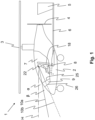
- Figure 1 shows a schematic side view of a gyroplane 1.
- the gyroplane 1 comprises a fuselage 2, on the upper side of which a rotor 3 is arranged.
- the rotor 3 is not driven by an engine, but can be set into autorotation by a headwind of the gyroplane 1.
- the gyroplane 1 receives lift through the rotor 3 set in autorotation.
- the gyroplane 1 In order to enable the gyroplane 1 to move forward, it has a propeller 4 in the rear area of the fuselage 2, which can be driven by a motor not shown here. In an area behind the propeller 4, a tail unit 5 is arranged, which is connected to the fuselage 2 by means of a strut 6. The gyroplane 1 can be controlled with the help of the tail unit 5.
- a cockpit 7 is arranged in which a gyroplane pilot 8 can sit.
- the pilot 8 can sit in a pilot seat 18.
- a dashboard 9 In the front area of the cockpit 7 there is a dashboard 9, via which the pilot 8 is informed of parameters of the gyroplane 1 and parameters of the flight. Additionally or alternatively, the pilot 8 can use it to control the gyroplane 1.
- the dashboard 9 is arranged in the field of vision of the pilot 8 so that he can see the displays.
- the dashboard 9 has a front side 25 facing the gyroplane pilot 8. On the side opposite the front side 25, the dashboard 9 has a back side 26.
- the dashboard 9 can also block the view of the pilot 8.
- a viewing direction 10a of the pilot 8 over the dashboard 9 is not blocked.
- a viewing direction 10b, however, is blocked by the dashboard 9.
- the viewing direction 10a has a flatter viewing angle ⁇ than the viewing direction 10b, so that in contrast to the viewing direction 10b, one can only look relatively far in front of the gyroplane 1. Events taking place closer to the gyroplane 1 that could be observed from the viewing direction 10b are obscured by the dashboard 9.
- a horizontal H can be defined which is oriented parallel to the surface of the gyroplane 1.
- the horizontal H can start from an eye point 22 of the pilot 8.
- the viewing angle ⁇ can be arranged between the horizontal H and the viewing direction 10a.
- the viewing angle ⁇ corresponds to the angle at which the pilot 8 still has a clear view in front of the gyroplane 1 and below the horizontal H.
- the viewing direction 10a runs just over the dashboard 9 below the viewing angle ⁇ . If the pilot 8 looks further down than the viewing angle ⁇ , his view is blocked by the dashboard 9.
- the viewing angle ⁇ can also be arranged between the horizontal H and the viewing direction 10b. In the present embodiment, at the viewing angle ⁇ , the pilot 8's view is blocked by the dashboard 9.
- a pilot's seat 18 is arranged in front of the dashboard 9.
- the pilot's seat 18 is arranged centrally in front of the dashboard 9 in a transverse direction of the gyroplane 1.
- the gyroplane 1 can also have at least one additional seat, not shown here, which is arranged in the cockpit 7.
- this at least one additional seat can be arranged behind the pilot seat 18 shown here, as seen from the dashboard 9.
- the additional seat can also be arranged transversely in the middle in front of the dashboard 9, but behind the pilot seat 18.
- the pilot seat 18 is arranged between the dashboard 9 and the additional seat.
- the dashboard 9, the pilot seat 18 and the said additional seat can be arranged one behind the other in the longitudinal direction of the gyroplane 1.
- At least one seat can be arranged next to the pilot seat 18.
- this additional seat cannot reach the dashboard 9 because the pilot's seat 18 with the pilot 8 is in between.
- the additional seat can be used to transport a guest.
- the additional seat can also be arranged higher than the pilot's seat 18, so that a better view is provided.
- At least one display and/or control unit can be arranged on the back of the pilot seat 18 facing away from the pilot 8.
- the guest on the additional seat can, for example, follow the travel route, speed, altitude, etc.
- the guest can, for example, enter or change the travel route.
- the display and/or control unit can be arranged, for example, on a backrest of the pilot's seat 18.
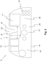
- FIG. 2 shows a schematic top view of the dashboard 9.
- the dashboard 9 comprises at least one display unit 11, whereby for the sake of simplicity only one display unit 11 is provided with a reference symbol. With the aid of the display unit 11, flight parameters and other information can be displayed to the pilot 8.
- the display unit 11 can, for example, comprise a digital display on which graphics can be shown.
- the display unit 11 can, however, also comprise an analog display.
- the dashboard 9 can also comprise at least one operating unit 12, whereby for the sake of simplicity only one operating unit 12 is provided with a reference number. This enables the pilot 8 control the gyrocopter 1 and/or enter control commands. Using an operating unit 12, the pilot 8 can, for example, set a frequency of a radio device. At least the operating unit 12 should be arranged on the dashboard 9 in such a way that it can be easily reached by the pilot 8 during the gyrocopter flight. Additionally or alternatively, the dashboard 9 can also be arranged in the cockpit 7 in such a way that the pilot 8 can reach all of the operating units 12 and/or display units 11. Due to the orientation of the at least one display unit 11, the dashboard 9 has a top side 13 and a bottom side 14.
- the display unit 11 and/or the operating unit 12 are arranged on the front side 25 of the dashboard 9.
- the dashboard 9 has at least one viewing window, which is formed by a recess 15 in the dashboard 9.
- the recess 15 extends from the upper side 13 towards the lower side 14.
- the recess 15 is arranged in a central area of the dashboard 9.
- the pilot 8 of the Figure 1 can thus look through the recess 15 so that he can observe the surroundings a short distance in front of the gyrocopter 1.
- the line of sight 10b along the viewing angle ⁇ can no longer be blocked by the recess 15.
- the pilot 8 can thus look through the recess 15 up to the viewing angle ⁇ below the horizontal H.
- the recess 15 on the upper side 13 of the dashboard 9 has an upper opening 23.
- the recess 15 has a width B that can be a maximum of 15 cm. Furthermore, the recess 15 has a depth T that can be a maximum of 25 cm. However, the depth T can also be so large that a gyrocopter pilot 8 of the 50th percentile in a side view of the gyrocopter 1 starting from his eye point 22 (cf. Figure 1 ) has a vertical viewing angle ⁇ of greater than or equal to 20° with respect to the horizontal H extending through the eye point 22. The line of sight 10b along the viewing angle ⁇ is no longer blocked by the recess 15. The pilot 8 can therefore still look forwards in front of the gyroplane 1 at the viewing angle ⁇ , which can be an angle of 20°.
- the pilot 8 can look through the recess 15 between the viewing angle ⁇ and the viewing angle ⁇ .
- the viewing angle ⁇ can also be greater than or equal to 25°, so that the pilot 8 can look even closer in front of the gyroplane 1.
- the viewing angle ⁇ can also be greater than or equal to 30°.
- the recess 15 allows the viewing angle 10b of the Figure 1 is no longer interrupted, so that events occurring in front of the gyroplane 1 can be detected. The flight safety of the gyroplane 1 is thereby increased.
- the dashboard 9 further comprises a left part 19 and a right part 20.
- a connecting part 21 is arranged between the left and right parts 19, 20.
- the recess 15 is arranged between the left part 19 and the right part 20.
- the left part 19, the connecting part 21 and the right part 20 are arranged such that the dashboard 9 has a U-shape.
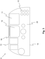
- FIG. 3 shows a further embodiment of the dashboard 9.
- the recess 15 is here at least partially surrounded by a stiffening strut 16.
- the stiffening strut 16 limits the recess 15 on the upper side 13 of the dashboard 9. With the help of the stiffening strut 16, the dashboard 9 can be made more stable.
- the stiffening strut 16 can also have display units 11 and/or operating units 12. Since the pilot 8 is the recess 15, the display units 11 and/or the control units 12 are directly in the field of vision of the pilot 8. Important information about the gyroplane 1 and/or the flight can thus be reliably communicated to the pilot 8.
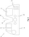
- Figure 4 shows a further embodiment of a dashboard 9.
- the recess 15 tapers from the top 13 towards the bottom 14.
- the recess 15 can taper conically.
- the recess 15 is V-shaped in the present embodiment.
- FIG. 5 shows a further embodiment of the dashboard 9.
- the dashboard 9 has at least one extension element 17a, 17b, which can comprise display units 11 and/or operating units 12.
- the dashboard 9 has two extension elements 17a, 17b.
- the at least one extension element 17a, 17b is according to Figure 5 on the underside 14 of the dashboard 9.
- the extension element 17a, 17b can, for example, be arranged on the dashboard 9 in a foldable manner so that it can be folded in to save space.
- the extension element 17a, 17b can also be detachably connected to the dashboard 9.
- the extension element 17a, 17b can thus be connected to the dashboard 9 and removed when not in use.
- the dashboard 9 has at least one interface (not shown here) to which the extension element 17a, 17b can be connected.
- the extension element 17a, 17b can, for example, be a GPS device that can be connected to the dashboard 9.
- FIG 6 shows a further embodiment of the dashboard 9 with a centrally arranged extension unit 17.
- the extension unit 17 is arranged in this embodiment centrally on the underside 14 of the dashboard 9. This allows the gyrocopter pilot 8 to look forwards in front of the gyrocopter 1 through the recess 15.
- the The gyrocopter pilot 8 can look diagonally to the left and right past the extension unit 17.
- the recess 15 and the extension unit can advantageously be located on a vertical axis according to the present embodiment.
- the dashboard 9 is installed correctly in the gyrocopter 1, the recess 15 is arranged above the extension unit 17. This gives the gyrocopter pilot 8 a clear view either through the recess 15 or past the side of the extension unit 17.
- Figure 7 shows a schematic view of a dashboard 9, which does not fall within the scope of the claims, with a recess 15, which is arranged on the underside 14.
- the recess 15 extends from the underside 14 towards the upper side 13.
- the pilot 8 can look steeply downwards in front of the gyroplane 1. This makes it possible, for example, to observe a front wheel of the gyroplane 1 and whether it is blocked by an object, for example.
- Figure 8 shows a schematic view of a dashboard 9, which does not fall within the scope of the claims, which is divided into two parts.
- the left part 19 is separated from the right part 20 by the recess 15.
- the recess 15 extends completely from the upper opening 23 to the lower opening 24 through the dashboard 9.
- the left part 19 and the right part 20 of the dashboard 9 can be connected to one another by means of at least one stiffening strut 16, not shown here.
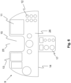
- FIG 9 shows a schematic view of a dashboard 9 with at least one anti-glare device 27, 28.
- the dashboard 9 has two anti-glare devices 27, 28.
- the first anti-glare device 27 is assigned to the left part 19 and the second anti-glare device 28 to the right part 20.
- the anti-glare devices 27, 28 are shown schematically here and can be designed as panels, for example.
- the at least one anti-glare device 27, 28 extends at least partially around the dashboard 9.
- the at least one anti-glare device 27, 28 extends away from the dashboard 9.
- the at least one anti-glare device 27, 28 extends when the dashboard 9 is arranged as intended in the gyroplane 1 (as is the case, for example, in Figure 1 shown) in the direction of the pilot's seat 18.
- the at least one anti-glare device 27, 28 also extends into the recess 15. With the aid of the anti-glare device 27, 28, sunlight can be blocked on the display unit 11 and/or the operating unit 12 so that they can be better recognized.
- the at least one anti-glare device 27, 28 is arranged such that a shadow falls on the display unit 11 and/or the operating unit 12.
Landscapes
- Engineering & Computer Science (AREA)
- Mechanical Engineering (AREA)
- Chemical & Material Sciences (AREA)
- Combustion & Propulsion (AREA)
- Transportation (AREA)
- Aviation & Aerospace Engineering (AREA)
- Instrument Panels (AREA)
Description
- Die vorliegende Erfindung betrifft einen Tragschrauber nach dem beigefügten Anspruch 1 mit einem in Autorotation versetzbaren Rotor, mit einem Armaturenbrett, das zumindest eine Anzeigeeinheit und/oder zumindest eine Bedieneinheit aufweist, wobei das Armaturenbrett zumindest ein Sichtfenster zur Sichtfelderweiterung für einen Tragschrauberpiloten aufweist, dass durch eine im Armaturenbrett ausgebildete Aussparung ausgebildet ist, und mit einem vor dem Armaturenbrett angeordneten Pilotensitz.
- Seit der Erfindung von Tragschraubern werden Armaturenbretter verwendet, um dem Piloten Flugparameter anzuzeigen und um Steuerungsmöglichkeiten des Fluggeräts bereitzustellen.
- In der
CN 105314099 A ist ein Drehflügler offenbart, welches vor einem Pilotensitz ein Armaturenbrett aufweist. - Aufgabe der vorliegenden Erfindung ist es somit, einen gegenüber dem Stand der Technik verbesserten Tragschrauber zu schaffen.
- Die Aufgabe wird gelöst durch einen Tragschrauber mit den Merkmalen des unabhängigen Patentanspruchs.
- Vorgeschlagen wird ein Tragschrauber mit einem in Autorotation versetzbaren Rotor, der einen Auftrieb für den Tragschrauber erzeugen kann. Ferner weist der Tragschrauber ein Armaturenbrett auf, das zumindest eine Anzeigeeinheit und/oder zumindest eine Bedieneinheit aufweist.
- Das Armaturenbrett für den Tragschrauber weist zumindest eine Anzeigeeinheit auf. Das Armaturenbrett kann somit ein Tragschrauberarmaturenbrett sein. Das Armaturenbrett ist in einem vorderen Bereich eines Cockpits des Tragschraubers angeordnet. Ein Tragschrauberpilot sitzt vor dem Armaturenbrett im Cockpit, so dass der Pilot das Armaturenbrett und die Anzeigeeinheit stets im Blick hat. Mit Hilfe der Anzeigeeinheit können dem Tragschrauberpiloten Parameter des Tragschraubers und des Fluges mitgeteilt werden. Mittels einer Anzeigeeinheit können beispielsweise eine Flughöhe, eine Fluggeschwindigkeit, eine Steigrate und/oder eine Sinkrate angezeigt werden. Die Anzeigeeinheit kann beispielsweise ein digitales Display und/oder eine analoge Anzeige umfassen. Des Weiteren können mehrere Flugparameter beispielsweise mit einer einzigen Anzeigeeinheit, beispielsweise als Display, angezeigt werden.
- Zusätzlich oder alternativ kann das Armaturenbrett auch zumindest eine Bedieneinheit aufweisen. Mit Hilfe der Bedieneinheit kann beispielsweise eine Frequenz eines Funkgeräts eingestellt werden.
- Das Armaturenbrett weist zumindest ein Sichtfenster zur Sichtfelderweiterung für den Tragschrauberpiloten auf, das durch eine im Armaturenbrett ausgebildete Aussparung ausgebildet ist. Die Aussparung ist das Sichtfenster, durch den der Pilot die Umgebung des Tragschraubers beobachten kann. Dadurch ist eine Flugsicherheit erhöht, da die verdeckten Bereiche der Umgebung für den Piloten verringert sind.
- Zusätzlich weist der Tragschrauber einen vor dem Armaturenbrett angeordneten Pilotensitz auf.
- Ferner ist der Pilotensitz in Querrichtung des Tragschraubers zentral mittig vor dem Armaturenbrett positioniert. Dadurch hat der Pilot einen zentralen Blick auf das Armaturenbrett und kann alle Stellen des Armaturenbretts bequem erreichen.
- Die Aussparung ist in Querrichtung des Armaturenbretts in einem Mittenbereich angeordnet, so dass dem Piloten eine Sicht nach vorne aus dem Tragschrauber möglich ist. Die Aussparung kann auch zentral mittig im Armaturenbrett angeordnet sein.
- Vorteilhaft ist es, wenn sich die Aussparung vollständig durch das Armaturenbrett hindurcherstreckt. Dadurch kann die Größe des Sichtfensters vergrößert werden, um dem Piloten ein größeres Sichtfeld zu ermöglichen. Zusätzlich oder alternativ kann die Aussparung von einer die Anzeigeeinheit und/oder Bedieneinheit aufweisenden Vorderseite des Armaturenbretts bis zu einer gegenüberliegenden Rückseite des Armaturenbretts reichen. Dadurch kann auf einen Bereich hinter die Rückseite des Armaturenbretts geblickt werden.
- Erfindungsgemäß erstreckt sich die Aussparung von einer Oberseite des Armaturenbretts ausgehend in Richtung einer Unterseite des Armaturenbretts.
- Die Ober- und die Unterseite beziehen sich dabei auf die verwendungsgemäße Orientierung des Armaturenbretts im Tragschrauber. Der Pilot blickt beispielsweise über die Oberseite des Armaturenbretts hinweg nach vorne. Die Aussparung erstreckt sich somit von oben nach unten. Dadurch kann der Pilot durch die Aussparung hindurch blicken und die Bereiche vor dem Tragschrauber beobachten.
- Zusätzlich oder alternativ weist die Aussparung im Bereich der Oberseite des Armaturenbretts eine obere Öffnung auf. Dadurch ist der Blick des Piloten nicht behindert.
- In Beispielen, die nicht in den Umfang der Ansprüche fallen, kann sich zumindest eine Aussparung von einer Unterseite des Armaturenbretts in Richtung einer Oberseite des Armaturenbretts erstrecken. Dadurch kann steil nach unten vor den Tragschrauber geblickt werden. Dadurch kann beispielsweise ein Vorderrad des Tragschraubers beobachtet werden.
- Außerdem erstreckt sich die Aussparung von der Oberseite ausgehend nur teilweise in Richtung der Unterseite, so dass das Armaturenbrett einen sich in Querrichtung des Armaturenbretts erstreckenden Verbindungsteil aufweist, der in der Vorderansicht einen linken und einen rechten Teil des Armaturenbretts miteinander verbindet. Dadurch kann das Armaturenbrett einteilig ausgebildet werden. Im Verbindungsteil können beispielsweise auch Kabel zur Übertragung von elektrischer Energie und/oder Kabel zur Kommunikation zwischen Anzeige- und/oder Bedieneinheiten des linken und rechten Teils angeordnet sein.
- Vorteilhaft ist es, wenn das Armaturenbrett in einer Vorderansicht eine U-Form aufweist. Der linke Teil, der Verbindungsteil und der rechte Teil sind damit so angeordnet, dass das Armaturenbrett die U-Form aufweist.
- In Beispielen, die nicht in den Umfang der Ansprüche fallen, kann sich die Aussparung von der Oberseite ausgehend vollständig bis zur Unterseite erstreckt, so dass die Aussparung im Bereich der Unterseite eine untere Öffnung aufweist. Dadurch ist der Blick des Piloten an der Unterseite des Armaturenbretts nicht behindert.
- In solchen Beispielen können der linke und der rechte Teil des Armaturenbretts voneinander getrennt sein. Dadurch ist ein großes Blickfeld in vertikaler Richtung vom Piloten aus gegeben. Der Pilot kann dadurch von oben nach unten zwischen den beiden Teilen des Armaturenbretts frei hindurch blicken.
- Von Vorteil ist es, wenn sich die Aussparung verjüngt. Dadurch kann ein Kompromiss zwischen einer Größe des Armaturenbretts und der Größe der Aussparung gefunden werden. Die Aussparung kann sich beispielsweise in Richtung der gegenüberliegenden Seite verjüngen.
- Die Aussparung kann sich dabei auch von der Vorderseite in Richtung der Rückseite verjüngen. Die Aussparung kann sich aber auch von der Rückseite in Richtung der Vorderseite verjüngen.
- Zusätzlich oder alternativ kann sich die Aussparung auch von der Oberseite in Richtung der Unterseite verjüngen. Alternativ kann sich die Aussparung auch von der Unterseite in Richtung der Oberseite verjüngen.
- Die Aussparung kann sich auch konisch verjüngen.
- Vorteilhaft ist es, wenn die Aussparung eine Breite von maximal 15 cm aufweist. Zusätzlich oder alternativ kann die Aussparung eine Tiefe von maximal 25 cm aufweisen. Dadurch weist die Aussparung eine ausreichende Größe auf, so dass der Pilot genug sieht.
- Um das Armaturenbrett stabiler auszubilden, kann das Armaturenbrett im Bereich der oberen Öffnung einen sich zwischen dem linken und dem rechten Teil des Armaturenbretts erstreckende Versteifungsstrebe aufweisen. Zusätzlich oder alternativ kann sich auch eine Versteifungsstrebe im Bereich der unteren Öffnung vom linken zum rechten Teil erstrecken.
- Vorteilhaft ist es, wenn die Versteifungsstrebe zumindest eine Anzeigeeinheit und/oder eine Bedieneinheit aufweist. Da die Versteifungsstrebe die Aussparung umrandet und der Pilot zumeist durch die Aussparung die Umgebung beobachtet, ist auch die zumindest eine Anzeigeeinheit im Blickfeld des Piloten. Wichtige Anzeigen, wie beispielsweise Flughöhe oder Fluggeschwindigkeit, können mittels der Anzeigeeinheit an der Versteifungsstrebe angezeigt werden, die der Pilot unmittelbar im Blick hat. Zusätzlich oder alternativ kann die Anzeigeeinheit und/oder die Bedieneinheit auch am Verbindungsteil angeordnet sein, so dass der Pilot die Anzeigeeinheit ebenfalls im Blick hat.
- Von Vorteil ist es des Weiteren, wenn das Armaturenbrett zumindest abschnittsweise eine Blendschutzvorrichtung aufweist. Die Blendschutzvorrichtung kann dabei um die Anzeigeeinheit und/oder um die Bedieneinheit angeordnet sein, so dass eine Sonneneinstrahlung auf die Anzeigeeinheit und/oder die Bedieneinheit geblockt wird. Dadurch kann trotz Sonneneinstrahlung die Anzeigeeinheit und/oder die Bedieneinheit vom Piloten erkannt werden. Die Blendschutzvorrichtung kann dabei auch im Bereich der Aussparung um das Armaturenbrett angeordnet sein. Die Blendschutzvorrichtung kann beispielsweise als eine Blende ausgebildet sein, die am Armaturenbrett angeordnet ist und sich von diesem weg erstreckt. Bei vorgesehener Verwendung des Armaturenbretts im Tragschrauber erstreckt sich die Blendschutzvorrichtung in Richtung des Piloten bzw. des Pilotensitzes. Die Blendschutzvorrichtung ist dabei derart angeordnet, dass der Schatten der Blendschutzvorrichtung auf die Anzeigeeinheit und/oder die Bedieneinheit fällt und diese dadurch verdunkelt.
- Um eine Größe des Armaturenbretts nicht zu sehr einzuschränken, kann das Armaturenbrett eine einzige Aussparung aufweisen.
- Vorteilhaft ist es auch, wenn das Armaturenbrett zumindest eine Erweiterungseinheit aufweist. Die Erweiterungseinheit kann beispielsweise an der Unterseite des Armaturenbretts angeordnet sein. Die Erweiterungseinheit kann beispielsweise klappbar am Armaturenbrett angeordnet sein, so dass diese weggeklappt werden kann, wenn diese nicht benutzt wird. Die Erweiterungseinheit kann auch lösbar mit dem Armaturenbrett verbunden sein, so dass diese am Armaturenbrett angeschlossen und wieder entfernt werden kann. Das Armaturenbrett kann dazu eine Schnittstelle aufweisen, an der die Erweiterungseinheit angeschlossen werden kann. Die Erweiterungseinheit kann zusätzliche Anzeigeeinheiten und/oder Bedieneinheiten aufweisen, um zusätzliche Funktionen und/oder Parameter des Tragschraubers anzeigen zu können. Beispielsweise kann die Erweiterungseinheit ein GPS-Gerät sein.
- Das GPS-Gerät kann am Armaturenbrett angeschlossen werden, um die Position des Tragschraubers am Armaturenbrett anzuzeigen.
- Ebenfalls ist es von Vorteil, wenn eine Tiefe einer Aussparung des Armaturenbretts derart groß ist, dass ein Tragschrauberpilot des 50. Perzentils in einer Seitenansicht des Tragschraubers ausgehend von seinem Augenpunkt gegenüber einer sich durch den Augenpunkt erstreckenden Horizontalen einen vertikalen Sichtwinkel größer oder gleich 20° aufweist. 50. Perzentil bedeutet dabei, dass 50% der Tragschrauberpiloten eine größere Körpergröße und 50% der Tragschrauberpiloten kleinere Körpergröße aufweisen.
- Durch den vertikalen Sichtwinkel von größer oder gleich 20°, kann der Pilot ausgehend von seinen Augen 20° oder weiter durch die Aussparung unter die Horizontale blicken. Er kann somit Ereignisse vor dem Tragschrauber sehen, die entsprechend nah vor dem Tragschrauber stattfinden.
- Der vertikale Sichtwinkel kann aber auch größer oder gleich 25° sein. Dadurch kann der Pilot Ereignisse vor dem Tragschrauber sehen, die noch näher am Tragschrauber stattfinden.
- Um dem Pilot eine noch bessere Sicht vor dem Tragschrauber zu ermöglichen, kann der vertikale Sichtwinkel auch 30° betragen.
- Von Vorteil ist es, wenn neben dem Pilotensitz, der zentral mittig vor dem Armaturenbrett angeordnet ist, zumindest ein weiterer Sitz angeordnet ist. Der Sitz kann dabei links oder rechts neben dem Pilotensitz angeordnet sein. Zusätzlich kann auch ein Sitz links und ein Sitz rechts neben dem Pilotensitz angeordnet sein. Der Pilotensitz weist somit zu beiden Seiten einen weiteren Sitz auf. Neben dem Pilotensitz bedeutet hier natürlich, dass der zumindest eine Sitz in Querrichtung des Tragschraubers neben dem Pilotensitz angeordnet ist
- Zusätzlich oder alternativ ist es vorteilhaft, wenn vom Armaturenbrett aus gesehen hinter dem Pilotensitz zumindest ein zusätzlicher Sitz angeordnet ist. Dabei können beispielsweise vom Armaturenbrett aus gesehen hinter dem Pilotensitz zumindest zwei oder mehr, beispielsweise drei, vier oder fünf, Sitze nebeneinander angeordnet sein. Hinter dem Pilotensitz kann auch eine Sitzbank für mehrere Personen angeordnet sein. Zusätzlich oder alternativ können auch zumindest drei Sitze in einer Reihe hintereinander, d.h. in Axialrichtung des Tragschraubers, angeordnet sein, wobei der vorderste bzw. der erste Sitz der Pilotensitz ist.
- Der zumindest eine weitere Sitz kann beispielsweise dazu genutzt werden, um eine Gastperson zu befördern. Dieser zumindest eine weitere Sitz kann, insbesondere wenn dieser hinter dem Pilotensitz angeordnet ist, gegenüber dem Pilotensitz erhöht im Tragschrauber angeordnet sein, so dass die Aussicht für die Gastperson verbessert ist. Wenn der zumindest eine weitere Sitz hinter dem Pilotensitz angeordnet ist, befindet er sich vom Armaturenbrett aus gesehen hinter dem Pilotensitz. Der Pilotensitz ist somit zwischen dem Armaturenbrett und dem weiteren bzw. zusätzlichen Sitz angeordnet. Der zusätzliche Sitz kann ebenfalls in Querrichtung mittig vor dem Armaturenbrett angeordnet sein, wobei der Pilotensitz zwischen dem Armaturenbrett und dem zusätzlichen Sitz angeordnet ist. Der zusätzliche Sitz kann auch in Querrichtung mittig im Tragschrauber angeordnet sein. Das Armaturenbrett, der Pilotensitz und der zusätzliche Sitz können in Längsrichtung des Tragschraubers hintereinander angeordnet sein. Der zusätzliche Sitz befindet sich natürlich ebenfalls im Cockpit des Tragschraubers.
- Der zumindest eine weitere Sitz kann auch ein Pilotensitz sein, wenn der Tragschrauber beispielsweise ein Übungstragschrauber ist, so dass ein Fluglehrer und ein Flugschüler den Tragschrauber steuern müssen. In dem zumindest einem weiteren Sitz bzw. Pilotensitz kann aber beispielsweise auch ein Copilot sitzen.
- Hinter und/oder neben dem Pilotensitz kann zusätzlich oder alternativ auch ein Lagerraum zum Transport von Waren angeordnet sein.
- Weitere Vorteile der Erfindung sind in den nachfolgenden Ausführungsbeispielen beschrieben. Es zeigen:
- Figur 1
- eine schematische Seitenansicht eines Tragschraubers,
- Figur 2
- eine schematische Draufsicht eines Armaturenbretts mit einer Aussparung,
- Figur 3
- eine schematische Draufsicht eines Armaturenbretts mit einem Steg, der die Aussparung umrandet,
- Figur 4
- eine schematische Draufsicht eines Armaturenbretts mit einer sich verjüngenden Aussparung,
- Figur 5
- eine schematische Draufsicht eines Armaturenbretts mit zumindest einer Erweiterungseinheit,
- Figur 6
- eine schematische Draufsicht eines Armaturenbretts mit einer mittig angeordneten Erweiterungseinheit,
- Figur 7
- eine schematische Draufsicht eines Armaturenbretts, das nicht in den Umfang der Ansprüche fällt, mit einer Aussparung an einer Unterseite,
- Figur 8
- eine schematische Draufsicht eines Armaturenbretts, das nicht in den Umfang der Ansprüche fällt, das zweigeteilt ist, und
- Figur 9
- eine schematische Draufsicht eines Armaturenbretts mit zumindest einer Blendschutzvorrichtung.
-
Figur 1 zeigt eine schematische Seitenansicht eines Tragschraubers 1. Der Tragschrauber 1 umfasst einen Rumpf 2, an dessen oberer Seite ein Rotor 3 angeordnet ist. Der Rotor 3 ist nicht von einem Motor angetrieben, sondern kann durch einen Fahrtwind des Tragschraubers 1 in Autorotation versetzt werden. Durch den in Autorotation versetzten Rotor 3 erhält der Tragschrauber 1 einen Auftrieb. - Um den Tragschrauber 1 in eine Vorwärtsfahrt zu versetzen, weist dieser im hinteren Bereich des Rumpfes 2 einen Propeller 4 auf, der von einem hier nicht gezeigten Motor angetrieben werden kann. In einem Bereich hinter dem Propeller 4 ist ein Leitwerk 5 angeordnet, das mittels einer Strebe 6 mit dem Rumpf 2 verbunden ist. Mit Hilfe des Leitwerks 5 kann der Tragschrauber 1 gesteuert werden.
- In einem vorderen Bereich des Rumpfes 2 ist ein Cockpit 7 angeordnet, in dem ein Tragschrauberpilot 8 sitzen kann. Der Pilot 8 kann dabei in einem Pilotensitz 18 sitzen.
- Im vorderen Bereich des Cockpits 7 ist ein Armaturenbrett 9 angeordnet, über das dem Pilot 8 Parameter des Tragschraubers 1 und Parameter des Fluges mitgeteilt bekommt. Zusätzlich oder alternativ kann der Pilot 8 mit dessen Hilfe den Tragschrauber 1 steuern. Das Armaturenbrett 9 ist dabei im Blickbereich des Piloten 8 angeordnet, so dass er die Anzeigen im Blick hat.
- Das Armaturenbrett 9 weist eine dem Tragschrauberpiloten 8 zugewandte Vorderseite 25 auf. An der zur Vorderseite 25 gegenüberliegenden Seite weist das Armaturenbrett 9 eine Rückseite 26 auf.
- Das Armaturenbrett 9 kann den Blick des Piloten 8 jedoch auch blockieren. Eine Blickrichtung 10a des Piloten 8 über das Armaturenbrett 9 hinweg ist nicht blockiert. Eine Blickrichtung 10b dagegen ist vom Armaturenbrett 9 blockiert. Die Blickrichtung 10a weist einen flacheren Sichtwinkel α als die Blickrichtung 10b auf, so dass im Gegensatz zur Blickrichtung 10b lediglich relativ weit vor den Tragschrauber 1 geblickt werden kann. Näher am Tragschrauber 1 stattfindende Ereignisse, die von der Blickrichtung 10b beobachtet werden könnten, sind vom Armaturenbrett 9 verdeckt.
- Ausgehend vom Piloten 8 kann eine Horizontale H definiert werden, die parallel zum Untergrund des Tragschraubers 1 orientiert ist. Die Horizontale H kann von einem Augenpunkt 22 des Piloten 8 ausgehen. Zwischen der Horizontalen H und der Blickrichtung 10a kann der Sichtwinkel α angeordnet sein. Der Sichtwinkel α entspricht dabei dem Winkel, bei dem der Pilot 8 noch freien Blick vor den Tragschrauber 1 und unterhalb der Horizontalen H hat. Die Blickrichtung 10a verläuft unter dem Sichtwinkel α gerade noch über das Armaturenbrett 9 hinweg. Blickt der Pilot 8 weiter als der Sichtwinkel α nach unten, ist sein Blick durch das Armaturenbrett 9 blockiert. Zwischen der Horizontalen H und der Blickrichtung 10b kann des Weiteren der Sichtwinkel β angeordnet sein. Im vorliegenden Ausführungsbeispiel ist beim Sichtwinkel β die Sicht des Piloten 8 durch das Armaturenbrett 9 blockiert.
- Vor dem Armaturenbrett 9 ist dabei ein Pilotensitz 18 angeordnet. Der Pilotensitz 18 ist in einer Querrichtung des Tragschraubers 1 mittig vor dem Armaturenbrett 9 angeordnet.
- Der Tragschrauber 1 kann auch zumindest einen weiteren, hier nicht gezeigten, Sitz aufweisen, der im Cockpit 7 angeordnet ist. Beispielsweise kann dieser zumindest eine zusätzliche Sitz vom Armaturenbrett 9 aus gesehen hinter dem hier gezeigten Pilotensitz 18 angeordnet sein. Der zusätzliche Sitz kann ebenfalls in Querrichtung mittig vor dem Armaturenbrett 9, allerdings hinter dem Pilotensitz 18, angeordnet sein. Zwischen dem Armaturenbrett 9 und dem zusätzlichen Sitz ist der Pilotensitz 18 angeordnet. Das Armaturenbrett 9, der Pilotensitz 18 und der besagte zusätzliche Sitz können in Längsrichtung des Tragschraubers 1 hintereinander angeordnet sein.
- Zusätzlich oder alternativ kann auch zumindest ein Sitz neben dem Pilotensitz 18 angeordnet sein.
- Eine Person, die auf diesem zusätzlichen Sitz sitzt, kann dann zwar das Armaturenbrett 9 nicht erreichen, da der Pilotensitz 18 mit dem Piloten 8 dazwischen sitzt. Der zusätzliche Sitz kann aber dazu dienen, eine Gastperson zu befördern. Der zusätzliche Sitz kann ferner gegenüber dem Pilotensitz 18 erhöht angeordnet sein, so dass dadurch eine bessere Aussicht gegeben ist.
- Beispielsweise können auf der zum Piloten 8 abgewandten Rückseite des Pilotensitzes 18 zumindest eine Anzeige- und/oder Bedieneinheit angeordnet sein. Mit Hilfe der Anzeigeeinheit kann die Gastperson auf dem zusätzlichen Sitz beispielsweise die Reiseroute, die Geschwindigkeit, Höhe etc. verfolgen. Mit Hilfe der Bedieneinheit kann die Gastperson beispielsweise die Reiseroute eingeben bzw. verändern.
- Die Anzeige- und/oder Bedieneinheit kann beispielsweise an einer Lehne des Pilotensitzes 18 angeordnet sein.
-
Figur 2 zeigt eine schematische Draufsicht auf das Armaturenbrett 9. Das Armaturenbrett 9 umfasst zumindest eine Anzeigeeinheit 11, wobei der Einfachheit halber lediglich eine Anzeigeeinheit 11 mit einem Bezugszeichen versehen ist. Mit Hilfe der Anzeigeeinheit 11 können Flugparameter und andere Information dem Piloten 8 angezeigt werden. Die Anzeigeeinheit 11 kann beispielsweise ein digitales Display umfassen, auf dem Grafiken angezeigt werden können. Die Anzeigeeinheit 11 kann aber auch eine analoge Anzeige umfassen. - Zusätzlich oder alternativ kann das Armaturenbrett 9 auch zumindest eine Bedieneinheit 12 umfassen, wobei der Einfachheit halber lediglich eine Bedieneinheit 12 mit einem Bezugszeichen versehen ist. Damit kann der Pilot 8 den Tragschrauber 1 steuern und/oder Regelbefehle eingeben. Mittels einer Bedieneinheit 12 kann der Pilot 8 beispielsweise eine Frequenz eines Funkgerätes einstellen. Zumindest die Bedieneinheit 12 sollte auf dem Armaturenbrett 9 derart angeordnet sein, dass diese vom Piloten 8 bequem während des Tragschrauberfluges erreichbar ist. Zusätzlich oder alternativ kann auch das Armaturenbrett 9 derart im Cockpit 7 angeordnet sein, dass der Pilot 8 alle Bedieneinheiten 12 und/oder Anzeigeeinheiten 11 erreicht. Durch die Orientierung der zumindest einen Anzeigeeinheit 11 weist das Armaturenbrett 9 eine Oberseite 13 und eine Unterseite 14 auf.
- Die Anzeigeeinheit 11 und/oder die Bedieneinheit 12 sind auf der Vorderseite 25 des Armaturenbretts 9 angeordnet.
- Um ein Sichtfeld für den Tragschrauberpilot 8 zu erweitern, weist das Armaturenbrett 9 zumindest ein Sichtfenster auf, das durch eine Aussparung 15 im Armaturenbrett 9 ausgebildet ist. Die Aussparung 15 erstreckt sich erfindungsgemäß ausgehend von der Oberseite 13 in Richtung Unterseite 14. Des Weiteren ist die Aussparung 15 in einem Mittenbereich des Armaturenbretts 9 angeordnet. Der Pilot 8 der
Figur 1 kann somit durch die Aussparung 15 hindurch blicken, so dass er die Umgebung in kurzer Entfernung vor dem Tragschrauber 1 beobachten kann. Insbesondere kann durch die Aussparung 15 die Blickrichtung 10b entlang des Sichtwinkels β nicht mehr blockiert sein. Der Pilot 8 kann damit bis zum Sichtwinkel β unterhalb die Horizontale H durch die Aussparung 15 blicken. - Im vorliegenden Ausführungsbeispiel weist die Aussparung 15 an der Oberseite 13 des Armaturenbretts 9 eine obere Öffnung 23 auf.
- Die Aussparung 15 weist eine Breite B auf, die maximal 15 cm betragen kann. Ferner weist die Aussparung 15 eine Tiefe T auf, die maximal 25 cm betragen kann. Die Tiefe T kann aber auch derart groß sein, dass ein Tragschrauberpilot 8 des 50. Perzentils in einer Seitensicht des Tragschraubers 1 ausgehend von seinem Augenpunkt 22 (vgl.
Figur 1 ) gegenüber der sich durch den Augenpunkt 22 erstreckenden Horizontalen H den vertikalen Sichtwinkel β größer oder gleich 20° aufweist. Durch die Aussparung 15 ist die Blickrichtung 10b entlang des Sichtwinkels β nicht mehr blockiert. Der Pilot 8 kann damit auch noch unter dem Sichtwinkel β, der einen Winkel von 20° aufweisen kann, nach vorne vor den Tragschrauber 1 blicken. Der Pilot 8 kann zwischen dem Sichtwinkel α und dem Sichtwinkel β durch die Aussparung 15 hindurch blicken. Der Sichtwinkel β kann aber auch größer oder gleich 25° sein, so dass der Pilot 8 noch näher vor den Tragschrauber 1 blicken kann. Um noch näher vor den Tragschrauber 1 blicken zu können, kann der Sichtwinkel β aber auch größer oder gleich 30° betragen. - Durch die Aussparung 15 ist beispielsweise der Blickwinkel 10b der
Figur 1 nicht mehr unterbrochen, so dass stattfindende Ereignisse vor dem Tragschrauber 1 erkannt werden können. Die Flugsicherheit des Tragschraubers 1 ist dadurch erhöht. - Das Armaturenbrett 9 weist ferner einen linken Teil 19 und einen rechten Teil 20 auf. Zwischen dem linken und dem rechten Teil 19, 20 ist ein Verbindungsteil 21 angeordnet. Die Aussparung 15 ist zwischen dem linken Teil 19 und dem rechten Teil 20 angeordnet. Gemäß dem vorliegenden Ausführungsbeispiel sind der linke Teil 19, das Verbindungsteil 21 und der rechte Teil 20 so angeordnet, dass das Armaturenbrett 9 eine U-Form aufweist.
-
Figur 3 zeigt ein weiteres Ausführungsbeispiel des Armaturenbretts 9. Die Aussparung 15 ist hier von einer Versteifungsstrebe 16 zumindest teilweise umrandet. Die Versteifungsstrebe 16 begrenzt die Aussparung 15 an der Oberseite 13 des Armaturenbretts 9. Mit Hilfe der Versteifungsstrebe 16 kann das Armaturenbrett 9 stabiler ausgebildet werden. Wie im vorliegenden Ausführungsbeispiel gezeigt ist, kann die Versteifungsstrebe 16 auch Anzeigeeinheiten 11 und/oder Bedieneinheiten 12 aufweisen. Da der Pilot 8 durch die Aussparung 15 blicken kann, sind die Anzeigeeinheiten 11 und/oder die Bedieneinheiten 12 direkt im Blickfeld des Piloten 8. Wichtige Informationen über den Tragschrauber 1 und/oder des Fluges können so dem Piloten 8 zuverlässig mitgeteilt werden. -
Figur 4 zeigt ein weiteres Ausführungsbeispiel eines Armaturenbretts 9. Hier verjüngt sich die Aussparung 15 von der Oberseite 13 in Richtung der Unterseite 14. Die Aussparung 15 kann sich konisch verjüngen. Die Aussparung 15 ist im vorliegenden Ausführungsbeispiel V-förmig ausgebildet. -
Figur 5 zeigt ein weiteres Ausführungsbeispiel des Armaturenbretts 9. Das Armaturenbrett 9 weist zumindest ein Erweiterungselement 17a, 17b auf, das Anzeigeeinheiten 11 und/oder Bedieneinheiten 12 umfassen kann. Im vorliegenden Ausführungsbeispiel weist das Armaturenbrett 9 zwei Erweiterungselemente 17a, 17b auf. Das zumindest eine Erweiterungselement 17a, 17b ist gemäßFigur 5 an der Unterseite 14 des Armaturenbretts 9 angeordnet. Das Erweiterungselement 17a, 17b kann beispielsweise klappbar an dem Armaturenbrett 9 angeordnet sein, so dass es zur Platzeinsparung eingeklappt werden kann. Das Erweiterungselement 17a, 17b kann auch lösbar mit dem Armaturenbrett 9 verbunden sein. Das Erweiterungselement 17a, 17b kann somit am Armaturenbrett 9 angeschlossen und bei Nichtbenutzung abgenommen werden. Das Armaturenbrett 9 weist dazu zumindest eine hier nicht gezeigte Schnittstelle auf, an der das Erweiterungselement 17a, 17b angeschlossen werden kann. Das Erweiterungselement 17a, 17b kann beispielsweise ein GPS-Gerät sein, das an das Armaturenbrett 9 angeschlossen werden kann. -
Figur 6 zeigt ein weiteres Ausführungsbeispiel des Armaturenbretts 9 mit einer mittig angeordneten Erweiterungseinheit 17. Die Erweiterungseinheit 17 ist in diesem Ausführungsbeispiel mittig an der Unterseite 14 des Armaturenbretts 9 angeordnet. Dadurch kann der Tragschrauberpilot 8 durch die Aussparung 15 nach vorne vor den Tragschrauber 1 blicken. Zusätzlich kann der Tragschrauberpilot 8 seitlich an der Erweiterungseinheit 17 vorbei nach schräg links und rechts vorne blicken. Vorteilhafterweise können die Aussparung 15 und die Erweiterungseinheit gemäß dem vorliegenden Ausführungsbeispiel auf einer Vertikalachse liegen. Die Aussparung 15 ist bei einem bestimmungsgemäßen Einbau des Armaturenbretts 9 in den Tragschrauber 1 über der Erweiterungseinheit 17 angeordnet. Dadurch ist ein freier Blick für den Tragschrauberpiloten 8 entweder durch die Aussparung 15 oder seitlich an der Erweiterungseinheit 17 vorbei gegeben. -
Figur 7 zeigt eine schematische Ansicht eines Armaturenbretts 9, das nicht in den Umfang der Ansprüche fällt, mit einer Aussparung 15, wobei diese an der Unterseite 14 angeordnet ist. Die Aussparung 15 erstreckt sich von der Unterseite 14 in Richtung der Oberseite 13. Mit einer derartigen Aussparung 15 kann der Pilot 8 steil nach unten vor den Tragschrauber 1 blicken. Dadurch kann beispielsweise ein Vorderrad des Tragschraubers 1 beobachtet werden und ob es beispielsweise durch einen Gegenstand blockiert ist. -
Figur 8 zeigt eine schematische Ansicht eines Armaturenbretts 9, das nicht in den Umfang der Ansprüche fällt, das zweigeteilt ist. Der linke Teil 19 ist vom rechten Teil 20 durch die Aussparung 15 getrennt. Die Aussparung 15 erstreckt sich vollständig von der oberen Öffnung 23 bis zur unteren Öffnung 24 durch das Armaturenbrett 9. Zusätzlich können der linke Teil 19 und der rechte Teil 20 des Armaturenbretts 9 mittels zumindest einer hier nicht gezeigten Versteifungsstrebe 16 miteinander verbunden sein. -
Figur 9 zeigt eine schematische Ansicht eines Armaturenbretts 9 mit zumindest einer Blendschutzvorrichtung 27, 28. Gemäß dem vorliegenden Ausführungsbeispiel weist das Armaturenbrett 9 zwei Blendschutzvorrichtungen 27, 28 auf. Die erste Blendschutzvorrichtung 27 ist dabei dem linken Teil 19 und die zweite Blendschutzvorrichtung 28 dem rechten Teil 20 zugeordnet. Die Blendschutzvorrichtungen 27, 28 sind hier schematisch dargestellt und können beispielsweise als Blenden ausgebildet sein. Die zumindest eine Blendschutzvorrichtung 27, 28 erstreckt sich zumindest abschnittsweise um das Armaturenbrett 9. Vom Armaturenbrett 9 erstreckt sich die zumindest eine Blendschutzvorrichtung 27, 28 weg. Insbesondere erstreckt sich die zumindest eine Blendschutzvorrichtung 27, 28 bei bestimmungsgemäßer Anordnung des Armaturenbretts 9 im Tragschrauber 1 (wie es beispielsweise inFigur 1 gezeigt ist) in Richtung des Pilotensitzes 18. Gemäß dem vorliegenden Ausführungsbeispiel erstreckt sich die zumindest eine Blendschutzvorrichtung 27, 28 ebenfalls in die Aussparung 15 hinein. Mit Hilfe der Blendschutzvorrichtung 27, 28 kann eine Sonneneinstrahlung auf die Anzeigeeinheit 11 und/oder Bedieneinheit 12 geblockt werden, so dass diese besser erkannt werden können. Insbesondere ist die zumindest eine Blendschutzvorrichtung 27, 28 derart angeordnet, dass ein Schatten auf die Anzeigeeinheit 11 und/oder die Bedieneinheit 12 fällt. - Die vorliegende Erfindung ist nicht auf die dargestellten und beschriebenen Ausführungsbeispiele beschränkt. Abwandlungen im Rahmen der Patentansprüche sind ebenso möglich wie eine Kombination der Merkmale, auch wenn diese in unterschiedlichen Ausführungsbeispielen dargestellt und beschrieben sind.
-
- 1
- Tragschrauber
- 2
- Rumpf
- 3
- Rotor
- 4
- Propeller
- 5
- Leitwerk
- 6
- Strebe
- 7
- Cockpit
- 8
- Tragschrauberpilot
- 9
- Armaturenbrett
- 10
- Blickrichtung
- 11
- Anzeigeeinheit
- 12
- Bedieneinheit
- 13
- Oberseite
- 14
- Unterseite
- 15
- Aussparung
- 16
- Versteifungsstrebe
- 17
- Erweiterungselement
- 18
- Pilotensitz
- 19
- linker Teil
- 20
- rechter Teil
- 21
- Verbindungsteil
- 22
- Augenpunkt
- 23
- obere Öffnung
- 24
- untere Öffnung
- 25
- Vorderseite
- 26
- Rückseite
- 27
- erste Blendschutzvorrichtung
- 28
- zweite Blendschutzvorrichtung
- H
- Horizontale
- α
- Sichtwinkel
- β
- Sichtwinkel
- T
- Tiefe der Aussparung
- B
- Breite der Aussparung
Claims (11)
- Tragschrauber (1) miteinem in Autorotation versetzbaren Rotor (3),einem Armaturenbrett (9), das zumindest eine Anzeigeeinheit (11) und/oder zumindest eine Bedieneinheit (12) aufweist, wobei das Armaturenbrett (9) zumindest ein Sichtfenster zur Sichtfelderweiterung für einen Tragschrauberpiloten (8) aufweist, das durch eine im Armaturenbrett (9) ausgebildete Aussparung (15) ausgebildet ist, und einem vor dem Armaturenbrett (9) angeordneten Pilotensitz (18), wobei der Pilotensitz (18) in Querrichtung des Tragschraubers (1) zentral mittig vor dem Armaturenbrett (9) positioniert ist, wobei die Aussparung (15) in Querrichtung des Armaturenbrettes (9) in einem Mittenbereich, insbesondere zentral mittig, angeordnet ist, dadurch gekennzeichnet, dass sich die Aussparung (15) von der Oberseite (13) ausgehend nur teilweise in Richtung der Unterseite (14) erstreckt, so dass das Armaturenbrett (9) ein sich in Querrichtung des Armaturenbretts (9) erstreckendes Verbindungsteil (21) aufweist, das in der Vorderansicht einen linken und einen rechten Teil (19, 20) des Armaturenbretts (9) miteinander verbindet.
- Tragschrauber nach Anspruch 1, dadurch gekennzeichnet, dass sichdie Aussparung (15) vollständig durch das Armaturenbrett (9) hindurcherstreckt und/odervon einer die Anzeigeeinheit (11) und/oder Bedieneinheit (12) aufweisenden Vorderseite (25) des Armaturenbretts (9) bis zu einer gegenüberliegenden Rückseite (26) des Armaturenbretts (9) reicht.
- Tragschrauber nach einem der vorherigen Ansprüche, dadurch gekennzeichnet, dass sich die Aussparung (15) von einer Oberseite (13) des Armaturenbretts (9) ausgehend in Richtung einer Unterseite (14) des Armaturenbretts (9) erstreckt und/oder
im Bereich der Oberseite (13) des Armaturenbretts (9) eine obere Öffnung (23) aufweist. - Tragschrauber nach einem der vorherigen Ansprüche, dadurch gekennzeichnet, dass das Armaturenbrett (9) in einer Vorderansicht eine U-Form aufweist.
- Tragschrauber nach einem der vorherigen Ansprüche, dadurch gekennzeichnet, dass sich die Aussparung (15), insbesondere von der Vorderseite (25) in Richtung der Rückseite (26) oder von der Rückseite (26) in Richtung der Vorderseite (25) und/oder von der Oberseite (13) in Richtung der Unterseite (14), vorzugsweise konisch, verjüngt.
- Tragschrauber nach einem der vorherigen Ansprüche, dadurch gekennzeichnet, dass die Aussparung (15) eine Breite (B) von maximal 15 cm und/oder eine Tiefe (T) von maximal 25 cm aufweist.
- Tragschrauber nach Anspruch 3, dadurch gekennzeichnet, dass das Armaturenbrett (9) im Bereich der oberen Öffnung (23) eine sich zwischen dem linken und dem rechten Teil (19, 20) des Armaturenbretts (9) erstreckende Versteifungsstrebe (16) aufweist.
- Tragschrauber nach einem der vorherigen Ansprüche 1 und/oder 7, dadurch gekennzeichnet, dass der Verbindungsteil (21) und/oder die Versteifungsstrebe (16) zumindest eine Anzeigeeinheit (11) und/oder zumindest eine Bedieneinheit (12) aufweisen.
- Tragschrauber nach einem der vorherigen Ansprüche, dadurch gekennzeichnet, dass das Armaturenbrett (9) zumindest abschnittsweise zumindest eine Blendschutzvorrichtung (27, 28) aufweist.
- Tragschrauber nach einem der vorherigen Ansprüche, dadurch gekennzeichnet, dass eine Tiefe (T) einer Aussparung (15) des Armaturenbretts (9) derart groß ist, dass ein Tragschrauberpilot (8) des 50. Perzentils in einer Seitenansicht des Tragschraubers (1) ausgehend von seinem Augenpunkt (22) gegenüber einer sich durch den Augenpunkt (22) erstreckenden Horizontalen (H) einen vertikalen Sichtwinkel (α, β) größer oder gleich 20°, vorzugsweise größer oder gleich 25°, besonders vorzugsweise größer oder gleich 30°, aufweist.
- Tragschrauber nach einem der vorherigen Ansprüche, dadurch gekennzeichnet, dass neben und/oder hinter dem Pilotensitz (18) zumindest ein zusätzlicher Sitz angeordnet ist.
Applications Claiming Priority (3)
| Application Number | Priority Date | Filing Date | Title |
|---|---|---|---|
| DE102017121072 | 2017-09-12 | ||
| DE102018101412.0A DE102018101412A1 (de) | 2017-09-12 | 2018-01-23 | Armaturenbrett für einen Tragschrauber |
| PCT/EP2018/074599 WO2019053058A1 (de) | 2017-09-12 | 2018-09-12 | Tragschrauber mit einem armaturenbrett |
Publications (3)
| Publication Number | Publication Date |
|---|---|
| EP3681797A1 EP3681797A1 (de) | 2020-07-22 |
| EP3681797C0 EP3681797C0 (de) | 2024-04-10 |
| EP3681797B1 true EP3681797B1 (de) | 2024-04-10 |
Family
ID=65441343
Family Applications (1)
| Application Number | Title | Priority Date | Filing Date |
|---|---|---|---|
| EP18769345.2A Active EP3681797B1 (de) | 2017-09-12 | 2018-09-12 | Tragschrauber mit einem armaturenbrett |
Country Status (5)
| Country | Link |
|---|---|
| US (1) | US11472541B2 (de) |
| EP (1) | EP3681797B1 (de) |
| CN (1) | CN111094127A (de) |
| DE (1) | DE102018101412A1 (de) |
| WO (1) | WO2019053058A1 (de) |
Families Citing this family (1)
| Publication number | Priority date | Publication date | Assignee | Title |
|---|---|---|---|---|
| US11425814B2 (en) | 2020-04-22 | 2022-08-23 | Rosemount Aerospace Inc. | Flexible circuit card assembly with preformed undulations for surveillance system hinge assembly |
Family Cites Families (19)
| Publication number | Priority date | Publication date | Assignee | Title |
|---|---|---|---|---|
| US6457670B1 (en) * | 2001-01-30 | 2002-10-01 | Roadable Aircraft Int'l | Counter rotating ducted fan flying vehicle |
| US7321318B2 (en) * | 2004-03-31 | 2008-01-22 | The Boeing Company | Methods and systems for controlling the display of information at an aircraft flight deck |
| JP2007118871A (ja) * | 2005-10-31 | 2007-05-17 | Suzuki Motor Corp | インストルメントパネル側方に窓を配置した車両の室内構造 |
| US8888042B2 (en) * | 2008-05-06 | 2014-11-18 | Bertil R. L. Werjefelt | Emergency vision apparatus |
| US8701953B2 (en) * | 2009-10-09 | 2014-04-22 | Raytheon Company | Electronic flight bag mounting system |
| EP2361832B1 (de) * | 2010-02-18 | 2013-05-29 | EUROCOPTER DEUTSCHLAND GmbH | Cockpit für ein Luftfahrzeug |
| FR2985578A1 (fr) * | 2012-01-09 | 2013-07-12 | Peugeot Citroen Automobiles Sa | Systeme d'affichage pour un vehicule automobile, comprenant un ecran fixe sur la planche de bord |
| US10843796B2 (en) * | 2012-02-10 | 2020-11-24 | Merlin Technology, Inc. | Rotorcraft advanced autopilot control arrangement and methods |
| FR2989164B1 (fr) * | 2012-04-06 | 2015-04-10 | Thales Sa | Systeme de visualisations modulaire pour helicoptere |
| US9612131B2 (en) * | 2012-04-09 | 2017-04-04 | The Boeing Company | Identifying and configuring controls on a control panel |
| FR2991295B1 (fr) * | 2012-06-04 | 2015-02-27 | Eurocopter France | Aeronef a grande visibilite |
| US8952831B2 (en) * | 2012-12-07 | 2015-02-10 | Sikorsky Aircraft Corporation | Enhancement of cockpit external visibility |
| FR2999526A1 (fr) * | 2012-12-13 | 2014-06-20 | Airbus Operations Sas | Cockpit d'aeronef a issue de secours par une glace centrale |
| FR3003841B1 (fr) * | 2013-03-26 | 2015-07-17 | Eurocopter France | Aeronef muni d'un cockpit a visibilite exterieure optimisee, et procede. |
| CN105314099B (zh) * | 2014-05-30 | 2018-10-12 | 王略 | 单人手控旋翼机 |
| CN106143884B (zh) * | 2015-03-19 | 2019-09-06 | 王略 | 全手控旋翼机 |
| DE102015213592A1 (de) * | 2015-07-20 | 2017-01-26 | Bombardier Transportation Gmbh | Führerstand für Fahrzeuge und Armaturenbrett |
| US10202194B2 (en) * | 2016-05-11 | 2019-02-12 | The Boeing Company | Tuned aircraft lighting for an improved flight experience |
| CN205819057U (zh) * | 2016-07-25 | 2016-12-21 | 魏伯卿 | 小视角汽车全视野屏幕装置 |
-
2018
- 2018-01-23 DE DE102018101412.0A patent/DE102018101412A1/de not_active Withdrawn
- 2018-09-12 WO PCT/EP2018/074599 patent/WO2019053058A1/de not_active Ceased
- 2018-09-12 EP EP18769345.2A patent/EP3681797B1/de active Active
- 2018-09-12 US US16/646,585 patent/US11472541B2/en active Active
- 2018-09-12 CN CN201880058816.6A patent/CN111094127A/zh active Pending
Also Published As
| Publication number | Publication date |
|---|---|
| US20200283133A1 (en) | 2020-09-10 |
| EP3681797A1 (de) | 2020-07-22 |
| WO2019053058A1 (de) | 2019-03-21 |
| DE102018101412A1 (de) | 2019-03-14 |
| US11472541B2 (en) | 2022-10-18 |
| CN111094127A (zh) | 2020-05-01 |
| EP3681797C0 (de) | 2024-04-10 |
Similar Documents
| Publication | Publication Date | Title |
|---|---|---|
| DE60303832T2 (de) | Flugzeuginstrumententafel | |
| EP3050795B1 (de) | Hubschrauberkabine | |
| DE69910344T2 (de) | Cockpitanzeige mit dreidimensionaler Flugbahnabweichungssymbolik | |
| DE102013008289A1 (de) | Flugzeugbereich | |
| DE102008059823B4 (de) | Informationssystem für Mitteilungen von Passagieren an Flugbegleitpersonal | |
| DE102016110863B4 (de) | Automatische Flugzeugsteuerungseinrichtung, Flugzeugcockpit, Verfahren zum Betrieb einer automatischen Flugzeugsteuerungseinrichtung und Computerprogramm | |
| DE10102938B4 (de) | Nicklage-Symbolik | |
| DE69625382T2 (de) | Flugzeuganzeige welche eine abweichungsskala und referenzindizien kombiniert | |
| DE202013010582U1 (de) | Halterungssystem in einem Kraftfahrzeug | |
| DE102017116822A1 (de) | Arbeitsmaschine mit Anzeigeeinrichtung | |
| DE69103311T2 (de) | Schleudersitz für Kampfflugzeug. | |
| DE102023130995B3 (de) | Verfahren zur Unterstützung eines Piloten bei der Steuerung eines Luftfahrzeugs, Assistenzsystem für einen Luftfahrzeugpiloten, und Luftfahrzeug | |
| EP3681797B1 (de) | Tragschrauber mit einem armaturenbrett | |
| DE102011077345A1 (de) | Verfahren und Vorrichtung zum Darstellen von Informationen mittels eines Dual-View-Displays in einer Passagierkabine eines Luft- oder Raumfahrzeuges | |
| EP1102038A1 (de) | Flugführungs-Display zur Anwendung in Flugzeug-Cockpit und Flugzeug-Simulationssystemen | |
| DE102011077344A1 (de) | Anzeigevorrichtung für eine Passagierkabine eines Luft- oder Raumfahrzeuges | |
| DE102014016324A1 (de) | Anzeigesystem für einen Kraftwagen, Kraftwagen mit einem Anzeigesystem und Verfahren zum Betreiben eines Anzeigesystems | |
| DE602005001801T2 (de) | Steuerungsanzeige mit Ermittlung der maximalen Steigung zum Steuern eines Flugzeuges im Bodenfolgeflug | |
| EP2899492B1 (de) | Winkelspiegelsystem | |
| EP2492189B1 (de) | Beobachtungskanal und Hubschrauberkabine | |
| DE2806375C2 (de) | ||
| DE19846337C1 (de) | Übungssimulator | |
| DE19615258A1 (de) | Flugzeuginstrument | |
| DE1506111A1 (de) | Geraet zur Anzeige von Landeinformationen fuer VTOL Flugzeuge | |
| DE102019108330A1 (de) | Faltbare Blickfeldanzeigevorrichtung |
Legal Events
| Date | Code | Title | Description |
|---|---|---|---|
| STAA | Information on the status of an ep patent application or granted ep patent |
Free format text: STATUS: UNKNOWN |
|
| STAA | Information on the status of an ep patent application or granted ep patent |
Free format text: STATUS: THE INTERNATIONAL PUBLICATION HAS BEEN MADE |
|
| PUAI | Public reference made under article 153(3) epc to a published international application that has entered the european phase |
Free format text: ORIGINAL CODE: 0009012 |
|
| STAA | Information on the status of an ep patent application or granted ep patent |
Free format text: STATUS: REQUEST FOR EXAMINATION WAS MADE |
|
| 17P | Request for examination filed |
Effective date: 20200409 |
|
| AK | Designated contracting states |
Kind code of ref document: A1 Designated state(s): AL AT BE BG CH CY CZ DE DK EE ES FI FR GB GR HR HU IE IS IT LI LT LU LV MC MK MT NL NO PL PT RO RS SE SI SK SM TR |
|
| AX | Request for extension of the european patent |
Extension state: BA ME |
|
| DAV | Request for validation of the european patent (deleted) | ||
| DAX | Request for extension of the european patent (deleted) | ||
| STAA | Information on the status of an ep patent application or granted ep patent |
Free format text: STATUS: EXAMINATION IS IN PROGRESS |
|
| 17Q | First examination report despatched |
Effective date: 20220209 |
|
| RIC1 | Information provided on ipc code assigned before grant |
Ipc: B60K 37/06 20060101ALI20230316BHEP Ipc: B60K 37/02 20060101ALI20230316BHEP Ipc: B60K 37/00 20060101ALI20230316BHEP Ipc: B60K 35/00 20060101ALI20230316BHEP Ipc: B64D 43/00 20060101ALI20230316BHEP Ipc: B64D 11/06 20060101ALI20230316BHEP Ipc: B64C 27/02 20060101AFI20230316BHEP |
|
| GRAP | Despatch of communication of intention to grant a patent |
Free format text: ORIGINAL CODE: EPIDOSNIGR1 |
|
| STAA | Information on the status of an ep patent application or granted ep patent |
Free format text: STATUS: GRANT OF PATENT IS INTENDED |
|
| INTG | Intention to grant announced |
Effective date: 20230426 |
|
| GRAJ | Information related to disapproval of communication of intention to grant by the applicant or resumption of examination proceedings by the epo deleted |
Free format text: ORIGINAL CODE: EPIDOSDIGR1 |
|
| STAA | Information on the status of an ep patent application or granted ep patent |
Free format text: STATUS: EXAMINATION IS IN PROGRESS |
|
| GRAP | Despatch of communication of intention to grant a patent |
Free format text: ORIGINAL CODE: EPIDOSNIGR1 |
|
| STAA | Information on the status of an ep patent application or granted ep patent |
Free format text: STATUS: GRANT OF PATENT IS INTENDED |
|
| INTC | Intention to grant announced (deleted) | ||
| INTG | Intention to grant announced |
Effective date: 20231024 |
|
| GRAS | Grant fee paid |
Free format text: ORIGINAL CODE: EPIDOSNIGR3 |
|
| GRAA | (expected) grant |
Free format text: ORIGINAL CODE: 0009210 |
|
| STAA | Information on the status of an ep patent application or granted ep patent |
Free format text: STATUS: THE PATENT HAS BEEN GRANTED |
|
| AK | Designated contracting states |
Kind code of ref document: B1 Designated state(s): AL AT BE BG CH CY CZ DE DK EE ES FI FR GB GR HR HU IE IS IT LI LT LU LV MC MK MT NL NO PL PT RO RS SE SI SK SM TR |
|
| REG | Reference to a national code |
Ref country code: GB Ref legal event code: FG4D Free format text: NOT ENGLISH |
|
| REG | Reference to a national code |
Ref country code: CH Ref legal event code: EP |
|
| REG | Reference to a national code |
Ref country code: DE Ref legal event code: R096 Ref document number: 502018014428 Country of ref document: DE |
|
| REG | Reference to a national code |
Ref country code: IE Ref legal event code: FG4D Free format text: LANGUAGE OF EP DOCUMENT: GERMAN |
|
| U01 | Request for unitary effect filed |
Effective date: 20240425 |
|
| U07 | Unitary effect registered |
Designated state(s): AT BE BG DE DK EE FI FR IT LT LU LV MT NL PT SE SI Effective date: 20240503 |
|
| PG25 | Lapsed in a contracting state [announced via postgrant information from national office to epo] |
Ref country code: IS Free format text: LAPSE BECAUSE OF FAILURE TO SUBMIT A TRANSLATION OF THE DESCRIPTION OR TO PAY THE FEE WITHIN THE PRESCRIBED TIME-LIMIT Effective date: 20240810 |
|
| PG25 | Lapsed in a contracting state [announced via postgrant information from national office to epo] |
Ref country code: HR Free format text: LAPSE BECAUSE OF FAILURE TO SUBMIT A TRANSLATION OF THE DESCRIPTION OR TO PAY THE FEE WITHIN THE PRESCRIBED TIME-LIMIT Effective date: 20240410 |
|
| PG25 | Lapsed in a contracting state [announced via postgrant information from national office to epo] |
Ref country code: GR Free format text: LAPSE BECAUSE OF FAILURE TO SUBMIT A TRANSLATION OF THE DESCRIPTION OR TO PAY THE FEE WITHIN THE PRESCRIBED TIME-LIMIT Effective date: 20240711 |
|
| U20 | Renewal fee for the european patent with unitary effect paid |
Year of fee payment: 7 Effective date: 20240912 |
|
| PG25 | Lapsed in a contracting state [announced via postgrant information from national office to epo] |
Ref country code: ES Free format text: LAPSE BECAUSE OF FAILURE TO SUBMIT A TRANSLATION OF THE DESCRIPTION OR TO PAY THE FEE WITHIN THE PRESCRIBED TIME-LIMIT Effective date: 20240410 |
|
| PG25 | Lapsed in a contracting state [announced via postgrant information from national office to epo] |
Ref country code: PL Free format text: LAPSE BECAUSE OF FAILURE TO SUBMIT A TRANSLATION OF THE DESCRIPTION OR TO PAY THE FEE WITHIN THE PRESCRIBED TIME-LIMIT Effective date: 20240410 |
|
| PG25 | Lapsed in a contracting state [announced via postgrant information from national office to epo] |
Ref country code: PL Free format text: LAPSE BECAUSE OF FAILURE TO SUBMIT A TRANSLATION OF THE DESCRIPTION OR TO PAY THE FEE WITHIN THE PRESCRIBED TIME-LIMIT Effective date: 20240410 Ref country code: NO Free format text: LAPSE BECAUSE OF FAILURE TO SUBMIT A TRANSLATION OF THE DESCRIPTION OR TO PAY THE FEE WITHIN THE PRESCRIBED TIME-LIMIT Effective date: 20240710 Ref country code: IS Free format text: LAPSE BECAUSE OF FAILURE TO SUBMIT A TRANSLATION OF THE DESCRIPTION OR TO PAY THE FEE WITHIN THE PRESCRIBED TIME-LIMIT Effective date: 20240810 Ref country code: HR Free format text: LAPSE BECAUSE OF FAILURE TO SUBMIT A TRANSLATION OF THE DESCRIPTION OR TO PAY THE FEE WITHIN THE PRESCRIBED TIME-LIMIT Effective date: 20240410 Ref country code: GR Free format text: LAPSE BECAUSE OF FAILURE TO SUBMIT A TRANSLATION OF THE DESCRIPTION OR TO PAY THE FEE WITHIN THE PRESCRIBED TIME-LIMIT Effective date: 20240711 Ref country code: ES Free format text: LAPSE BECAUSE OF FAILURE TO SUBMIT A TRANSLATION OF THE DESCRIPTION OR TO PAY THE FEE WITHIN THE PRESCRIBED TIME-LIMIT Effective date: 20240410 Ref country code: RS Free format text: LAPSE BECAUSE OF FAILURE TO SUBMIT A TRANSLATION OF THE DESCRIPTION OR TO PAY THE FEE WITHIN THE PRESCRIBED TIME-LIMIT Effective date: 20240710 |
|
| REG | Reference to a national code |
Ref country code: DE Ref legal event code: R097 Ref document number: 502018014428 Country of ref document: DE |
|
| PG25 | Lapsed in a contracting state [announced via postgrant information from national office to epo] |
Ref country code: CZ Free format text: LAPSE BECAUSE OF FAILURE TO SUBMIT A TRANSLATION OF THE DESCRIPTION OR TO PAY THE FEE WITHIN THE PRESCRIBED TIME-LIMIT Effective date: 20240410 |
|
| PG25 | Lapsed in a contracting state [announced via postgrant information from national office to epo] |
Ref country code: SK Free format text: LAPSE BECAUSE OF FAILURE TO SUBMIT A TRANSLATION OF THE DESCRIPTION OR TO PAY THE FEE WITHIN THE PRESCRIBED TIME-LIMIT Effective date: 20240410 Ref country code: RO Free format text: LAPSE BECAUSE OF FAILURE TO SUBMIT A TRANSLATION OF THE DESCRIPTION OR TO PAY THE FEE WITHIN THE PRESCRIBED TIME-LIMIT Effective date: 20240410 |
|
| PG25 | Lapsed in a contracting state [announced via postgrant information from national office to epo] |
Ref country code: SM Free format text: LAPSE BECAUSE OF FAILURE TO SUBMIT A TRANSLATION OF THE DESCRIPTION OR TO PAY THE FEE WITHIN THE PRESCRIBED TIME-LIMIT Effective date: 20240410 |
|
| PG25 | Lapsed in a contracting state [announced via postgrant information from national office to epo] |
Ref country code: SM Free format text: LAPSE BECAUSE OF FAILURE TO SUBMIT A TRANSLATION OF THE DESCRIPTION OR TO PAY THE FEE WITHIN THE PRESCRIBED TIME-LIMIT Effective date: 20240410 Ref country code: SK Free format text: LAPSE BECAUSE OF FAILURE TO SUBMIT A TRANSLATION OF THE DESCRIPTION OR TO PAY THE FEE WITHIN THE PRESCRIBED TIME-LIMIT Effective date: 20240410 Ref country code: RO Free format text: LAPSE BECAUSE OF FAILURE TO SUBMIT A TRANSLATION OF THE DESCRIPTION OR TO PAY THE FEE WITHIN THE PRESCRIBED TIME-LIMIT Effective date: 20240410 Ref country code: CZ Free format text: LAPSE BECAUSE OF FAILURE TO SUBMIT A TRANSLATION OF THE DESCRIPTION OR TO PAY THE FEE WITHIN THE PRESCRIBED TIME-LIMIT Effective date: 20240410 |
|
| PLBE | No opposition filed within time limit |
Free format text: ORIGINAL CODE: 0009261 |
|
| STAA | Information on the status of an ep patent application or granted ep patent |
Free format text: STATUS: NO OPPOSITION FILED WITHIN TIME LIMIT |
|
| 26N | No opposition filed |
Effective date: 20250113 |
|
| PG25 | Lapsed in a contracting state [announced via postgrant information from national office to epo] |
Ref country code: MC Free format text: LAPSE BECAUSE OF FAILURE TO SUBMIT A TRANSLATION OF THE DESCRIPTION OR TO PAY THE FEE WITHIN THE PRESCRIBED TIME-LIMIT Effective date: 20240410 |
|
| REG | Reference to a national code |
Ref country code: CH Ref legal event code: PL |
|
| GBPC | Gb: european patent ceased through non-payment of renewal fee |
Effective date: 20240912 |
|
| PG25 | Lapsed in a contracting state [announced via postgrant information from national office to epo] |
Ref country code: GB Free format text: LAPSE BECAUSE OF NON-PAYMENT OF DUE FEES Effective date: 20240912 |
|
| PG25 | Lapsed in a contracting state [announced via postgrant information from national office to epo] |
Ref country code: CH Free format text: LAPSE BECAUSE OF NON-PAYMENT OF DUE FEES Effective date: 20240930 |
|
| PG25 | Lapsed in a contracting state [announced via postgrant information from national office to epo] |
Ref country code: IE Free format text: LAPSE BECAUSE OF NON-PAYMENT OF DUE FEES Effective date: 20240912 |
|
| PG25 | Lapsed in a contracting state [announced via postgrant information from national office to epo] |
Ref country code: CY Free format text: LAPSE BECAUSE OF FAILURE TO SUBMIT A TRANSLATION OF THE DESCRIPTION OR TO PAY THE FEE WITHIN THE PRESCRIBED TIME-LIMIT; INVALID AB INITIO Effective date: 20180912 |
|
| PG25 | Lapsed in a contracting state [announced via postgrant information from national office to epo] |
Ref country code: HU Free format text: LAPSE BECAUSE OF FAILURE TO SUBMIT A TRANSLATION OF THE DESCRIPTION OR TO PAY THE FEE WITHIN THE PRESCRIBED TIME-LIMIT; INVALID AB INITIO Effective date: 20180912 |