EP3681739B1 - Vorrichtung zur bewertung der festigkeit eines bodens - Google Patents
Vorrichtung zur bewertung der festigkeit eines bodens Download PDFInfo
- Publication number
- EP3681739B1 EP3681739B1 EP18780192.3A EP18780192A EP3681739B1 EP 3681739 B1 EP3681739 B1 EP 3681739B1 EP 18780192 A EP18780192 A EP 18780192A EP 3681739 B1 EP3681739 B1 EP 3681739B1
- Authority
- EP
- European Patent Office
- Prior art keywords
- curvature
- signal
- ground
- firmness
- evaluating
- Prior art date
- Legal status (The legal status is an assumption and is not a legal conclusion. Google has not performed a legal analysis and makes no representation as to the accuracy of the status listed.)
- Active
Links
Images


Classifications
-
- B—PERFORMING OPERATIONS; TRANSPORTING
- B60—VEHICLES IN GENERAL
- B60C—VEHICLE TYRES; TYRE INFLATION; TYRE CHANGING; CONNECTING VALVES TO INFLATABLE ELASTIC BODIES IN GENERAL; DEVICES OR ARRANGEMENTS RELATED TO TYRES
- B60C23/00—Devices for measuring, signalling, controlling, or distributing tyre pressure or temperature, specially adapted for mounting on vehicles; Arrangement of tyre inflating devices on vehicles, e.g. of pumps or of tanks; Tyre cooling arrangements
- B60C23/06—Signalling devices actuated by deformation of the tyre, e.g. tyre mounted deformation sensors or indirect determination of tyre deformation based on wheel speed, wheel-centre to ground distance or inclination of wheel axle
- B60C23/064—Signalling devices actuated by deformation of the tyre, e.g. tyre mounted deformation sensors or indirect determination of tyre deformation based on wheel speed, wheel-centre to ground distance or inclination of wheel axle comprising tyre mounted deformation sensors, e.g. to determine road contact area
-
- B—PERFORMING OPERATIONS; TRANSPORTING
- B60—VEHICLES IN GENERAL
- B60T—VEHICLE BRAKE CONTROL SYSTEMS OR PARTS THEREOF; BRAKE CONTROL SYSTEMS OR PARTS THEREOF, IN GENERAL; ARRANGEMENT OF BRAKING ELEMENTS ON VEHICLES IN GENERAL; PORTABLE DEVICES FOR PREVENTING UNWANTED MOVEMENT OF VEHICLES; VEHICLE MODIFICATIONS TO FACILITATE COOLING OF BRAKES
- B60T8/00—Arrangements for adjusting wheel-braking force to meet varying vehicular or ground-surface conditions, e.g. limiting or varying distribution of braking force
- B60T8/17—Using electrical or electronic regulation means to control braking
- B60T8/172—Determining control parameters used in the regulation, e.g. by calculations involving measured or detected parameters
- B60T8/1725—Using tyre sensors, e.g. Sidewall Torsion sensors [SWT]
-
- B—PERFORMING OPERATIONS; TRANSPORTING
- B60—VEHICLES IN GENERAL
- B60W—CONJOINT CONTROL OF VEHICLE SUB-UNITS OF DIFFERENT TYPE OR DIFFERENT FUNCTION; CONTROL SYSTEMS SPECIALLY ADAPTED FOR HYBRID VEHICLES; ROAD VEHICLE DRIVE CONTROL SYSTEMS FOR PURPOSES NOT RELATED TO THE CONTROL OF A PARTICULAR SUB-UNIT
- B60W40/00—Estimation or calculation of non-directly measurable driving parameters for road vehicle drive control systems not related to the control of a particular sub unit, e.g. by using mathematical models
- B60W40/02—Estimation or calculation of non-directly measurable driving parameters for road vehicle drive control systems not related to the control of a particular sub unit, e.g. by using mathematical models related to ambient conditions
- B60W40/06—Road conditions
-
- B—PERFORMING OPERATIONS; TRANSPORTING
- B60—VEHICLES IN GENERAL
- B60C—VEHICLE TYRES; TYRE INFLATION; TYRE CHANGING; CONNECTING VALVES TO INFLATABLE ELASTIC BODIES IN GENERAL; DEVICES OR ARRANGEMENTS RELATED TO TYRES
- B60C19/00—Tyre parts or constructions not otherwise provided for
- B60C2019/004—Tyre sensors other than for detecting tyre pressure
-
- B—PERFORMING OPERATIONS; TRANSPORTING
- B60—VEHICLES IN GENERAL
- B60T—VEHICLE BRAKE CONTROL SYSTEMS OR PARTS THEREOF; BRAKE CONTROL SYSTEMS OR PARTS THEREOF, IN GENERAL; ARRANGEMENT OF BRAKING ELEMENTS ON VEHICLES IN GENERAL; PORTABLE DEVICES FOR PREVENTING UNWANTED MOVEMENT OF VEHICLES; VEHICLE MODIFICATIONS TO FACILITATE COOLING OF BRAKES
- B60T2210/00—Detection or estimation of road or environment conditions; Detection or estimation of road shapes
- B60T2210/10—Detection or estimation of road conditions
-
- B—PERFORMING OPERATIONS; TRANSPORTING
- B60—VEHICLES IN GENERAL
- B60W—CONJOINT CONTROL OF VEHICLE SUB-UNITS OF DIFFERENT TYPE OR DIFFERENT FUNCTION; CONTROL SYSTEMS SPECIALLY ADAPTED FOR HYBRID VEHICLES; ROAD VEHICLE DRIVE CONTROL SYSTEMS FOR PURPOSES NOT RELATED TO THE CONTROL OF A PARTICULAR SUB-UNIT
- B60W2530/00—Input parameters relating to vehicle conditions or values, not covered by groups B60W2510/00 or B60W2520/00
- B60W2530/20—Tyre data
-
- B—PERFORMING OPERATIONS; TRANSPORTING
- B60—VEHICLES IN GENERAL
- B60W—CONJOINT CONTROL OF VEHICLE SUB-UNITS OF DIFFERENT TYPE OR DIFFERENT FUNCTION; CONTROL SYSTEMS SPECIALLY ADAPTED FOR HYBRID VEHICLES; ROAD VEHICLE DRIVE CONTROL SYSTEMS FOR PURPOSES NOT RELATED TO THE CONTROL OF A PARTICULAR SUB-UNIT
- B60W2552/00—Input parameters relating to infrastructure
Definitions
- the present invention relates to a method for evaluating the firmness of a ground on which a mounted assembly runs, comprising a pneumatic casing equipped with a device for measuring the deformation of the pneumatic casing.
- a soil is an assembly of three phases: a gas phase, a liquid phase and a solid phase, the proportions of which between the three phases define the characteristics of the soil. If the soil is sensitive to water content, the soil presents itself in three types of states qualified as solid, plastic and liquid according to its water content. the transition from one state to another determines the ease of tillage or mobility on this soil.
- EP0887211 A1 describes a sensor sensitive to the circumferential curvature positioned at the right of the top of the pneumatic casing.
- the invention aims to provide a method of instantaneous measurement of the firmness of a soil through a measurement on the pneumatic casing of a mounted assembly. a vehicle in use condition for the driver of the vehicle without affecting the efficiency of his work.
- the term “sensor sensitive to the circumferential curvature” is understood here to mean that the sensor delivers a physical quantity directly or indirectly related to the curvature of the pneumatic casing situated to the right of the sensor in the direction circumferential of the pneumatic casing.
- the sensor is equipped with all the components necessary to generate a signal that can be used by an external system in an analog or digital manner with sufficient spatial or temporal discretization to generate an output signal similar to a square type signal. It is a signal whose abscissa is a direct or indirect descriptor of the turn of the wheel and the ordinate is a direct or indirect descriptor of the circumferential curvature observed by the sensor.
- This sensor can be a resistive-type bending sensor, a piezoelectric sensor sensitive to bending, an accelerometer whose DC component is proportional to the radial acceleration of the pneumatic casing or any other sensor based on a mechanical or electrical measurement, magnetic or optical delivering a DC component proportional to the circumferential curvature of the pneumatic casing.
- equipped is understood here to mean that at least part of the sensor is linked to the pneumatic casing.
- sensor is understood here to mean the measuring device comprising both the active sensor proper and the additional components for generating an exploitable signal.
- optical sensor is understood here to mean any device of the state of the art making it possible to obtain blistering of the surface of the pneumatic casing when passing through the contact area by an optical measurement.
- the document EP1820670A1 describes a solution comprising on the one hand a calibrated pattern subjected to the deformation of a surface of the pneumatic casing, for example a part of the contact area.
- the measuring device comprises lighting means, coupled to viewing means, mounted on the rim of the wheel of the assembly mounted at a certain azimuthal position.
- these lighting and vision means are of the stereovision type.
- This device makes it possible to obtain a visualization of the blistering of the surface of the pneumatic casing when the calibrated pattern of the contact area passes through.
- the calibration of the pattern makes it possible to deduce therefrom the circumferential curvature of the surface of the tire at the level of the calibrated pattern situated for example in the contact area.
- radial rigidity of the mounted assembly is understood here to mean the dynamic rigidity of the mounted assembly generated by a radial displacement imposed at the level of the outer surface of the crown in the elastic range of the displacements observed by a pneumatic casing in nominal condition of use. These conditions determine in particular the imposed load and the inflation pressure.
- This dynamic rigidity is the ratio between the vertical force observed at the wheel center of the mounted assembly and the imposed vertical displacement of the top of the tire casing at the level of the contact area in the frequency range between 5 and 50 Hz for which the assembled assembly behaves like a unidirectional spring which corresponds to a measurement far removed from the eigen modes of the assembled assembly.
- the type of sensor used makes it possible to observe the curvature of the pneumatic envelope which will develop when the sensor is located entirely in the contact area.
- This sensor does not wish to detect the variations in curvature at the level of the transition zones of the envelope passing from a state of contact type with the ground to a state of type not in contact with the ground. It just seeks to identify the resulting curvature of the pneumatic casing when the area of the pneumatic casing to the right of the sensor is in the contact area.
- the signals from the sensor are similar to a square-wave type signal in which the value representative of the plateau of the square-wave is extracted by suitable mathematical means.
- This representative value of the plateau is the image of the average curvature of the pneumatic casing in the contact area.
- the isolated fronts of the square wave correspond to the measurement by the sensor of the curvature of the pneumatic casing in the transition zone between the two steady-state states in terms of the boundary conditions applied to the zone of the mounted assembly located to the right. of the sensor.
- curvature values depend on the conditions of use of the pneumatic casing. In particular, these values are a function of the inflation pressure, the load carried and the speed of rotation of the pneumatic casing.
- steady-state curvature value of the contact with the ground type is also sensitive to the rigidity of the ground. Thus the differential between the two curvature values makes it possible to go back to the desired information concerning the firmness of the ground.
- the coefficients ⁇ , ⁇ 1 and ⁇ 2 are coefficients dependent on the assembled assembly.
- This relative curvature is between 0 and 1.
- the zero value of C corresponds to a zero curvature value in the contact area which is similar to a plane ground equivalent to a high firmness of the ground.
- the unit value of C corresponds to an identical curvature inside and outside the contact area. This results in an absence of contact area around the wheel in the sense of flattening the tire casing.
- the tire has the same curvature in any angular position of the turn of the wheel and this corresponds to the maximum value of curvature in the steady-state zones corresponding to the casing in contact with the ground.
- the intermediate values correspond to intermediate curvatures of the pneumatic casing in areas of steady state contact with the ground.
- the conditions of use of the mounted assembly such as, for example, the load carried, the inflation pressure or the speed of rotation only slightly influence the relative curvature C of the pneumatic casing which is mainly controlled. by the firmness of the soil.
- dependent on the mounted assembly is understood to mean that the very nature of the components of the mounted assembly, such as at least the pneumatic casing or the wheel, strongly influences their dimensional and material characteristics. Conversely, the conditions of use of the mounted assembly such as the inflation pressure, the applied load or the speed of rotation are weakly dependent parameters.
- the relative curvature value C tends towards 0. Therefore the firmness of the ground becomes important compared to the radial rigidity of the mounted assembly. Likewise, when the ground is of low firmness, the value of relative curvature tends towards 1. The relative firmness of the ground with respect to the radial rigidity of the mounted assembly tends towards 0.
- the pneumatic casing defining a contact area, by application of the nominal conditions of use of the mounted assembly, this contact area having a Ladc dimension in the axial direction of the mounted assembly, the sensor measures the average circumferential curvature over a length between 10% and 80% of the Ladc dimension.
- nominal conditions of use of a pneumatic casing is understood here to mean the standard conditions of the pneumatic casing according to the ETRTO standard in order to define the geometric box of the pneumatic casing.
- the nominal conditions relate to the load carried, the inflation pressure as well as the dimensions and characteristics of the wheel on which the tire casing is mounted. For a given pneumatic envelope, these conditions specify a contact area on a rigid plane ground including a maximum contact area Ladc length.
- the measurement made by the sensor corresponds to the average curvature of the pneumatic envelope over the length of the sensor.
- This type of sensor is much less sensitive to stiffness irregularities originating from the ground or from the pneumatic casing or from the mounted assembly. It therefore provides statistically more reliable information on the firmness of a soil in a homogenized and direct form.
- this type of sensor generates a greater dynamic in the measurement of curvature between the permanent speeds corresponding to the rotation. free or in contact with the ground.
- This dynamic measurement makes it possible to assess the firmness of a soil with greater finesse.
- the larger the sensor the better the measurement dynamics and the precision of the homogenized value of the firmness of a soil. Necessarily, in order to obtain a signal emitted by the sensor which can be used by the method, it is necessary for the length of the sensor to be less than the length of the contact area under the soil measurement conditions.
- the pneumatic casing defining a contact area, this contact area having a ladc dimension in the transverse direction of the mounted assembly, the sensor measures the average circumferential curvature over a width of between 10% and 80% of the ladc dimension.
- the measurement made by the sensor corresponds to the average curvature of the pneumatic casing over the length and width of the sensor.
- This type of sensor is much less sensitive to stiffness irregularities originating from the ground or from the pneumatic casing or from the mounted assembly. It therefore provides statistically more reliable information on the firmness of a soil in a homogenized and direct form. Necessarily, in order to obtain a signal emitted by the sensor which can be used by the method, it is necessary for the width of the sensor to be less than the width of the contact area under the soil measurement conditions.
- the senor measures the average curvature of a zone of the top of the pneumatic casing in contact with the ground which is homogeneous in terms of radial rigidity.
- the crown comprises in particular a tread which is the element in direct contact with the ground.
- This tread is often constituted by longitudinal and / or transverse chains of hollows and protruding sculptures locally modifying the radial rigidity of the pneumatic casing. It is therefore advisable to position the sensor in line with a homogeneous zone in terms of rigidity and in particular radial rigidity.
- the senor measures the average curvature of a zone of the crown in line with a tread element of the tread of the pneumatic casing.
- the senor In the same logic of the quality of the measurement information, it is preferable for the sensor to be positioned in line with a tread pattern element. This ensures homogeneity of the radial rigidity of the pneumatic casing and therefore of the mounted assembly.
- the tread is an element of the protruding tread which is in direct contact with the ground.
- the other elements of the tread such as the hollows for example, although also interacting with the ground, are also influenced by the other parts of the tread such as the protruding elements. Consequently, the measurement obtained when the sensor is in line with a tread pattern element therefore has more dynamics making the intrinsic qualification of the ground more precise.
- This method for obtaining an evaluation of the curvatures of the assembly mounted in these permanent speeds in terms of the boundary conditions applied to the tire casing is based on the generation of a signal emitted by the multi-slot type sensor on the revolution of the wheel.
- a first signal emitted by the sensor corresponding to a finite number N of wheel revolutions is isolated.
- the rotation of the mounted assembly is detected using a sensor available in the state of the art integrated into the casing tire, the assembled assembly or the vehicle such as for example a top lathe or an encoder.
- This transmitted signal is isolated beforehand into elementary signals of the single pulse type in order to simplify the identification of the value of curvature of each steady state.
- the splitting is carried out by isolating the signal between two local maxima of the signal. Each local maxima corresponds to a transition zone from a first steady state to a second steady state.
- This method is particularly well suited for sampling a soil whose characteristics have already been noted.
- a one-off measurement is sufficient for the temporal monitoring of a plot of soil.
- the output quantity of the sensor is influenced by parameters which change during the revolution of the wheel and over time when the measurement is taken, such as for example the angular speed of the mounted assembly or the temperature
- these variations must be taken into account.
- the sensor calibration curve must be taken into account.
- the signal recorded by the sensor such as for example the radial acceleration in the case of an accelerometer depending both on the curvature and on the displacement speed of the mounted assembly, by integrating the effects of varying these parameters in the recorded signal.
- the measurements of the variable parameters must be evaluated simultaneously with the signal recorded by the sensor sensitive to the circumferential curvature, using additional devices if necessary. These additional devices are both measuring devices and devices for synchronizing all of the measuring signals.
- the new recorded signal is thus cleaned of parasitic fluctuations.
- a sensor is thus produced which directly measures the circumferential curvature.
- the shape of the new signals is characteristic of what is expected, a multi-slot signal. The signal processing performed in the general method is then applicable.
- the curvature of the pneumatic casing in the condition of contact with the ground ⁇ j is evaluated on a signal reduced from the first signal.
- the condition on the length of the intervals makes it possible to isolate on the recorded signal the square wave corresponding to the permanent state of contact with the ground. Then, on this niche which comprises first and second isolated fronts representing the passage of the sensor between a first permanent mode out of contact with the ground to a permanent mode of contact with the ground then to a second passage in the opposite direction between the permanent modes, it is voluntarily restricted to a portion of the signal which represents the condition that one seeks to analyze. Indeed, interactions between the assembled assembly and the soil can modify the local rigidity of the soil, which corresponds to a soil compaction operation. The visualization of the compaction of the soil is observed by the value of the plateau of the niche of the first signal. This changes as the sensor passes through the contact area. Depending on the information you are looking for, it may be advantageous to restrict the measurement to certain areas of the contact area.
- the reduced signal of the first signal is defined as being the first half of the first signal.
- the first part of the contact area of the pneumatic casing is located opposite a floor which has undergone only a slight influence from the mounted assembly.
- the value of curvature of the tire casing identified makes it possible to obtain an evaluation of the relative firmness value of the ground which is an intrinsic datum on the ground not influenced by the passage of the assembly mounted on this ground.
- the reduced signal of the first signal is defined as being the second half of the first signal.
- the second part of the contact area of the pneumatic casing is located opposite a so-called rolled ground which has been influenced by the pneumatic casing. Therefore, the value of curvature of the pneumatic casing identified makes it possible to obtain an evaluation of the value of relative firmness of the rolled ground which has undergone the passage of the mounted assembly.
- This data is an interesting quantity since it corresponds to the state of the ground after the passage of the assembled assembly. It is therefore a characteristic of the ground resulting from the action of the mounted assembly and of the vehicle.
- This method makes it possible to generate a signal of the square type.
- the starting point resides in a signal 102 emitted by a sensor sensitive to the circumferential curvature.
- the spatial discretization of this signal must be sufficient to adequately describe the passage through the contact area. A minimum of six measuring points in the contact area is necessary.
- This signal can be a direct measurement of the circumferential curvature via a bending sensor or an indirect measurement via, for example, a single-axis accelerometer disposed radially to the pneumatic casing or a piezoelectric sensor whose main direction is positioned ciconferentially to the tire. pneumatic envelope.
- This signal can be supplemented by other signals 101 and 103 useful for using the curvature signal 102.
- the curvature signal 102 is influenced by variable parameters, it is necessary, in order to correct the curvature signal 102, also to record the variation of these variable parameters.
- a signal 103 of the encoder type or a top turn is also needed to isolate the response of the signals on the turn of the wheel of the mounted assembly.
- the synchronization 104 of all of these signals is a prerequisite for any information processing method.
- the method generates curvature signals 108 corresponding to a finite number N of wheel revolutions which have been corrected, if necessary, for fluctuations in the variable parameters.
- the second process consists in determining the representative values of the circumferential curvature in each of the permanent speeds of the mounted assembly.
- steady state is understood here to mean that the boundary conditions applied to the zone of the top of the pneumatic casing situated to the right of the sensor are identical, that is to say either in contact with the ground or outside the sensor. contact with the ground.
- the curvature signal 108 corresponding to each of these zones delimited by the local maxima is similar to a square wave having two edges of strong variation in curvature separated by a plate having an almost constant level of curvature. Isolated fronts correspond to the transition zones between the steady state zones. The plateau corresponds to the stable zone in terms of boundary conditions applied to the top of the pneumatic casing where the measurement sensor is located. It is this part of the signal which will subsequently be used.
- a representative value of curvature associated with the mounted assembly will be determined. The determination of this representative value is carried out by mathematical methods such as minimum value, median value, least squares method or any other algorithm.
- the first representative value 111 or 113 called ⁇ j corresponds to the mean curvature in steady state of boundary conditions of contact with the ground type.
- the second representative value 112 or 114 called ⁇ j + 1 designates the mean curvature in steady state outside contact with the ground.
- the last process is to evaluate the relative firmness of the ground 120 versus the radial stiffness of the mounted assembly from the curvature values of the mounted assembly 115 and 116 taken individually or in combination. If the greatness linked to the circumferential curvature 116 in permanent contact with the ground type ⁇ A taking into account the rigidity of the ground is the most relevant, the taking into account of the circumferential curvature 115 out of contact with the ground ⁇ B quantitatively improves the determination of soil firmness.
- the firmness of the ground during the penetration of the pneumatic casing into the ground by focusing on the first half of the square wave signal plate in the direction of advance of the mounted assembly. This measurement is intrinsic to the soil. It is also possible to measure the firmness of the soil on the second half of the contact area giving access to the firmness of the soil which may have been modified by the passage of the assembled assembly. The difference between these two distinctive characteristics of the firmness of a soil makes it possible to return to a magnitude similar to soil compaction after the passage of the mounted assembly.
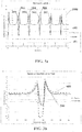
- the figure 2 includes the responses of sensors sensitive to the circumferential curvature of the piezoelectric type when these are installed on a Michelin Multibib brand tire casing in size 650/60 R38 when running on a Fendt Turbomatik Favorit 614 LSA tractor.
- This pneumatic casing has two series of bars positioned on the lateral parts of the tread angularly offset with respect to one another. In fact, each bar starts from the center of the apex and extends in a direction making an angle of approximately 30 degrees alternately clockwise and counterclockwise with respect to the X axis towards the exterior.
- a first piezoelectric sensor is positioned on the inner rubber of the pneumatic casing with the active part of the sensor fixed to the right of a strip. In order to optimize the signal response, this sensor is located closest to the middle of the tread.
- a second sensor is positioned to the right of an inter strip zone, that is to say between two strips. This sensor is also centered at best in relation to the width of the top.
- the assembled assembly will roll on two floors of different firmness.
- the first floor is an asphalt road of high rigidity.
- the second soil is an agricultural field without cultivation and without plowing for several days.
- the mounted assembly is inflated to a pressure of 1.6 bar and the tractor drives at a constant speed of 10 km / h both on the road and in the agricultural field.
- the curves in bold 201 and 203 represent the response of the first piezoelectric sensor, the active part of which is located in line with a strip of the tread.
- the curves in thin lines 202 and 204 are the responses of the second sensor located in the inter-strip zone.
- the continuous line curves 201 and 202 correspond to driving on the road, while the dotted curves 203 and 204 correspond to driving in the agricultural field.
- the signals observed are the 10-wheel average of the raw outputs of the piezoelectric sensor in volts over a full revolution of the wheel.
- the origin of the angles is located in the vertical direction, according to the positive Zs in the Galilean coordinate system.
- the strong change located around 180 degrees corresponds to the response of the sensor as it passes through the contact area.
- the response of the second sensor is not sufficiently discriminating.
- the amplitude of the response of the second sensor is markedly lower than that of the first sensor, in particular at the level of the slot plateau, comparison of the curves 202 and 201 or 203 and 204
- the amplitude of the response of the second sensor is similar and whatever the nature of the ground, comparison of curves 202 and 204.
- the sensor sensitive to the circumferential curvature of the pneumatic casing allows the iso condition of use of the assembled assembly, that is to say the same inflation pressure, the same load applied and the same rolling speed, to qualify the soils relatively according to their firmness.
- the figure 3a shows on the one hand the temporal recording of an electrical signal emitted by the sensor sensitive to the circumferential curvature noted 400 and on the other hand a top turn encoder noted 401.
- the signals are synchronized and discretized at a sampling frequency of 2400Hz.
- the piezoelectric type curvature sensor is installed on a Michelin Multibib tire casing in size 650/60 R38 when driving on a Fendt Turbomatik Favorit 614 LSA tractor.
- the tractor rolls over soil of a certain stiffness at a constant speed of 10 km / h.
- the assembled assembly is here inflated to a pressure of 1.6 bars.
- a conversion of the sensor output voltage to curvature is provided. It would also have been possible to use the output signal of an accelerometer positioned to the right of the tread pattern delivering the radial acceleration of the tire casing which would have been low frequency filtered and corrected by the speed of rotation. of the assembled assembly. This rotational speed is determined, for example, using the top wheel revolution.
- a recorded signal corresponding to 5 revolutions of the wheel will be extracted. This recorded signal is that contained in the dotted box 1000.
- this recorded signal contains 10 local maximums noted from 501, that is to say two per revolution of the wheel. These local maximums correspond to the moment when the sensor sensitive to the circumferential curvature enters or leaves the contact area. The spatial difference between two neighboring local maxima differs greatly. Thus, by taking a local maximum 506, the local maxima preceding 505 and following 507 are respectively close to and far from the maximum 506.
- the circumferential length of the pneumatic casing in the contact area being markedly smaller than the remaining circumferential length of the l pneumatic casing. It is obvious that the maximum 505 corresponds to the entry into the contact area, the maximum 506 the exit of the contact area for the same turn of the wheel. Finally, the maximum 507 is the entry into the contact area for the next turn of the wheel.
- the figure 3b contains the averages over 5 revolutions of the wheel of the responses of the curvature sensor mounted on the tire rolling either on soft ground 500 or on firm ground 600.
- the conditions of use of the pneumatic tire that is, mainly say the inflation pressure, applied load and rolling speed are the same.
- the curvature of the pneumatic casing outside the contact zone is almost constant with a curvature of approximately six degrees. Consistently, the curvature observed by the tire casing outside the contact zone decreases if the mounted assembly rolls on soft ground compared to that obtained on rigid ground.
- the curvature in the contact zone is very different depending on the nature of the soil. On firm ground, the curvature is low due to the flattening of the tire casing. On the other hand on a soft ground, one observes indeed a fall of the curvature compared to the condition out of contact with the ground but the resulting curvature is still of the order in this case of 50% of the curvature out of contact with the ground.
- the algorithm used for the evaluation of the curvature is the median value of the points on the whole plateau.
- a curvature value in contact with the soil ⁇ A of 3.2 degrees and a curvature value out of contact with the soil ⁇ B of approximately 5.9 degrees are identified.
- a value of curvature in contact with the ground ⁇ A ' of about 0.5 degrees and a value of curvature out of contact with the ground ⁇ B' d ' about 6.1 degrees.
- a first value of relative curvature on soft ground denoted C of the order of 0.54 and a second relative curvature value of the firm ground denoted C 'of the order of 0.082 is determined.
- the measurement protocol identifies a curvature value in contact with the ground ⁇ A ' of approximately 1 degree and a curvature value out of contact with the ground ⁇ B' of approximately 6.1 degrees.
- the relative curvature value C ′ of the order of 0.16 is identified for the firm ground.
Landscapes
- Engineering & Computer Science (AREA)
- Mechanical Engineering (AREA)
- Transportation (AREA)
- Physics & Mathematics (AREA)
- Automation & Control Theory (AREA)
- Mathematical Physics (AREA)
- Tires In General (AREA)
- Length Measuring Devices With Unspecified Measuring Means (AREA)
Claims (15)
- Verfahren zur Bewertung der Festigkeit eines Bodens, auf dem ein Fahrzeug fährt, das mindestens eine montierte Einheit mit einer radialen Steifheit kradial hat, die einen Reifenmantel mit einem Scheitel, zwei Flanken und einem Wulst enthält, der mit mindestens einem für die Umfangskrümmung empfindlichen Sensor ausgestattet ist, der gegenüber dem Scheitel positioniert ist, das die folgenden Schritt enthält:- Schätzen eines Krümmungswerts ρA des Reifenmantels entsprechend einem ersten Beharrungszustand des Reifenmantels in Kontakt mit dem Boden;- Bewerten der relativen Festigkeit des Bodens bezüglich der radialen Steifheit kradial der montierten Einheit als eine Funktion des Krümmungswerts ρA des Reifenmantels.
- Verfahren zur Bewertung der Festigkeit eines Bodens nach dem vorhergehenden Anspruch, das die folgenden Schritte enthält:- Schätzen eines Krümmungswerts ρB des Reifenmantels entsprechend einem zweiten Beharrungszustand des Reifenmantels ohne Kontakt mit dem Boden;- Bewerten der relativen Festigkeit des Bodens bezüglich der radialen Steifheit kradial der montierten Einheit als eine Funktion der Krümmungswerte ρA und ρB des Reifenmantels.
- Verfahren zur Bewertung der Festigkeit eines Bodens nach dem vorhergehenden Anspruch, das die folgenden Schritte enthält:- Erstellen der relativen Krümmung C als das Verhältnis der Krümmungen ρA/ρB des Reifenmantels in Kontakt oder ohne Kontakt mit dem Boden;- Bewerten der relativen Festigkeit des Bodens bezüglich der radialen Steifheit kradial der montierten Einheit als eine Funktion der relativen Krümmung C.
- Verfahren zur Bewertung der Festigkeit eines Bodens nach dem vorhergehenden Anspruch, das die folgenden Schritte enthält:- Bewerten der relativen Festigkeit des Bodens bezüglich der radialen Steifheit kradial der montierten Einheit durch Anwenden der folgenden Formel, in der die Parameter α, β1 und β2 abhängige Koeffizienten der montierten Einheit und P der Fülldruck der montierten Einheit ist:

- Verfahren zur Bewertung der Festigkeit des Bodens nach einem der vorhergehenden Ansprüche, wobei, da der Reifenmantel durch Anwendung der Nennbedingungen der Nutzung der montierten Einheit einen Kontaktbereich definiert, der eine Abmessung Ladc gemäß der axialen Richtung der montierten Einheit aufweist, der mindestens eine Sensor bei jeder Messung die mittlere Umfangskrümmung über eine Länge zwischen 10% und 80% der Abmessung Ladc bewertet.
- Verfahren zur Bewertung der Festigkeit des Bodens nach Anspruch 5, wobei, da der Reifenmantel einen Kontaktbereich definiert, der eine Abmessung ladc gemäß der Querrichtung der montierten Einheit aufweist, der mindestens eine Sensor bei jeder Messung die mittlere Umfangskrümmung über eine Breite zwischen 10% und 80% der Breite ladc bewertet.
- Verfahren zur Bewertung der Festigkeit des Bodens nach einem der vorhergehenden Ansprüche, wobei der Sensor die mittlere Krümmung eines Bereichs des Scheitels des Reifenmantels in Kontakt mit dem Boden misst, der bezüglich der radialen Steifheit homogen ist.
- Verfahren zur Bewertung der Festigkeit des Bodens nach dem vorhergehenden Anspruch, wobei der Sensor die mittlere Krümmung eines Bereichs des Scheitels gegenüber einem Profilelement des Laufstreifens des Reifenmantels misst.
- Verfahren zur Bewertung der Festigkeit eines Bodens nach einem der vorhergehenden Ansprüche, wobei die Schätzung der Krümmungswerte entsprechend den ersten und zweiten Beharrungszuständen bezüglich von Bedingungen an den Grenzen des Reifenmantels die folgenden Schritte enthält:- Erhalt eines gespeicherten Signals des für die Krümmung empfindlichen Sensors entsprechend N Radumdrehungen der montierten Einheit, wobei N eine ganze Zahl strikt größer als 1 ist;- Erkennen in dem gespeicherten Signal der 2N lokalen Maxima Y2N und ihrer entsprechenden Abszissen X2N;- für jedes j eine ganze Zahl strikt größer als 1 und strikt kleiner als 2N:wenn gilt (Xj-Xj-1) < (Xj+1-Xj),a) Isolieren eines ersten Signals auf dem gespeicherten Signal zwischen dem zentralen Maximum (Xj, Yj) und dem vorhergehenden Maximum (Xj-1, Yj-1) ;b) Erkennen des Krümmungswerts im Beharrungszustand genannt ρj auf dem ersten Signal;c) Isolieren eines zweiten Signals auf dem gespeicherten Signal zwischen dem zentralen Maximum (Xj, Yj) und dem folgenden Maximum (Xj+1, Yj+1) ; undd) Erkennen des Krümmungswerts im Beharrungszustand genannt ρj+1 auf dem zweiten Signal;sonsta) Isolieren eines ersten Signals auf dem gespeicherten Signal zwischen dem zentralen Maximum (Xj, Yj) und dem folgenden Maximum (Xj+1, Yj+1) ;b) Erkennen des Krümmungswerts im Beharrungszustand genannt ρj auf dem ersten Signal;c) Isolieren eines zweiten Signals auf dem gespeicherten Signal zwischen dem zentralen Maximum (Xj, Yj) und dem vorhergehenden Maximum (Xj-1, Yj-1) ; undd) Erkennen des Krümmungswerts im Beharrungszustand genannt ρj+1 auf dem zweiten Signal;- Erstellen der Krümmung des Reifenmantels im Zustand des Kontakts mit dem Boden ρA als der Mittelwert der mindestens einen Krümmungswerte ρj und der Krümmung des Reifenmantels im Zustand ohne Kontakt mit dem Boden ρB als der Mittelwert der mindestens einen Krümmungswerte ρj+1.
- Verfahren zur Bewertung der Festigkeit eines Bodens nach Anspruch 9, wobei der Erhalt des gespeicherten Signals des für die Krümmung empfindlichen Sensors entsprechend N Radumdrehungen der montierten Einheit die folgenden Schritte enthält:- Speichern eines vom für die Krümmung empfindlichen Sensor gesendeten Signals entsprechend einer Radumdrehung der montierten Einheit;- Periodisieren des gesendeten Signals über N Perioden, wobei N eine ganze Zahl größer als 1 ist.
- Verfahren zur Bewertung der Festigkeit eines Bodens nach einem der vorhergehenden Ansprüche 9 und 10, wobei, da der Sensor eine indirekte Größe der Umfangskrümmung des Reifenmantels ausgibt, die mindestens einen variablen Parameter einsetzt, das Verfahren einen zusätzlichen Schritt enthält:- Korrigieren der indirekten Größe auf dem gespeicherten Signal mit Hilfe des mindestens einen variablen Parameters.
- Verfahren zur Bewertung der Festigkeit des Bodens nach einem der Ansprüche 9 bis 11, wobei die Krümmung des Reifenmantels im Zustand des Kontakts mit dem Boden ρj auf einem reduzierten Signal des ersten Signals bewertet wird.
- Verfahren zur Bewertung der Festigkeit des Bodens nach Anspruch 12, wobei das reduzierte Signal des ersten Signals der ersten Hälfte des ersten Signals entspricht.
- Verfahren zur Bewertung der Festigkeit des Bodens nach Anspruch 12, wobei das reduzierte Signal des ersten Signals der zweiten Hälfte des ersten Signals entspricht.
- Verfahren zur Bewertung der Festigkeit des Bodens nach einem der Ansprüche 13 und 14, wobei die Erkennung der Krümmungswerte im Zustand des Kontakts mit dem Boden ρj den folgenden Schritt enthält:- Symmetrisieren des reduzierten Signals auf ein Intervall entsprechend dem reduzierten Signal, um ein neues Signal in Form eines Rechtecksignals zu erhalten.
Applications Claiming Priority (2)
| Application Number | Priority Date | Filing Date | Title |
|---|---|---|---|
| FR1758531A FR3071064A1 (fr) | 2017-09-14 | 2017-09-14 | Methode d'evaluation de la fermete d'un sol |
| PCT/FR2018/052257 WO2019053384A1 (fr) | 2017-09-14 | 2018-09-14 | Methode d'evaluation de la fermete d'un sol |
Publications (2)
| Publication Number | Publication Date |
|---|---|
| EP3681739A1 EP3681739A1 (de) | 2020-07-22 |
| EP3681739B1 true EP3681739B1 (de) | 2021-10-27 |
Family
ID=60450833
Family Applications (1)
| Application Number | Title | Priority Date | Filing Date |
|---|---|---|---|
| EP18780192.3A Active EP3681739B1 (de) | 2017-09-14 | 2018-09-14 | Vorrichtung zur bewertung der festigkeit eines bodens |
Country Status (7)
| Country | Link |
|---|---|
| US (1) | US11230148B2 (de) |
| EP (1) | EP3681739B1 (de) |
| CN (1) | CN111315599B (de) |
| BR (1) | BR112020005098B1 (de) |
| EA (1) | EA038291B1 (de) |
| FR (1) | FR3071064A1 (de) |
| WO (1) | WO2019053384A1 (de) |
Families Citing this family (10)
| Publication number | Priority date | Publication date | Assignee | Title |
|---|---|---|---|---|
| US12054015B2 (en) * | 2017-11-24 | 2024-08-06 | Pirelli Tyre S.P.A. | Method and system for monitoring a parameter related to a tire during the running of a vehicle |
| FR3088426B3 (fr) * | 2018-11-14 | 2020-10-16 | Michelin & Cie | Procede de determination de la charge appliquee sur un pneumatique |
| CN113661109B (zh) * | 2019-04-05 | 2024-01-02 | 沃尔沃卡车集团 | 用于确定指示支撑车辆的地面段的承载能力的值的控制单元和方法 |
| CN111806166B (zh) * | 2020-06-24 | 2021-08-31 | 浙江大学 | 一种基于摩擦起电材料的地形监测轮胎 |
| CN112632750B (zh) * | 2020-12-01 | 2023-09-26 | 北方信息控制研究院集团有限公司 | 虚拟战场环境不同要素相互耦合的仿真建模方法及系统 |
| FR3125983B1 (fr) * | 2021-08-06 | 2023-07-21 | Michelin & Cie | Methode d’obtention de la deformation d’un pneumatique soumis a une charge en roulage |
| FR3130694B1 (fr) * | 2021-12-16 | 2024-02-16 | Michelin & Cie | Procede de determination de l’humidite d’un sol agraire |
| CN114943608B (zh) * | 2022-06-24 | 2025-09-23 | 中国农业银行股份有限公司 | 一种欺诈风险评估方法、装置、设备及存储介质 |
| CN116380108B (zh) * | 2023-06-02 | 2023-08-11 | 山东科技大学 | 一种基于激光雷达的轨迹规划方法及设备 |
| CN118220155B (zh) * | 2024-05-27 | 2024-09-20 | 长城汽车股份有限公司 | 一种行驶模式的控制方法、系统及车辆 |
Family Cites Families (13)
| Publication number | Priority date | Publication date | Assignee | Title |
|---|---|---|---|---|
| GB190623058A (en) * | 1906-10-18 | 1907-09-26 | Frederick William Brown | Improvements in, and relating to Wheels for Vehicles |
| KR0168098B1 (ko) * | 1993-10-05 | 1999-01-15 | 전성원 | 주행도로의 가혹도 평가장치 및 그 방법 |
| US5610330A (en) * | 1996-01-16 | 1997-03-11 | Ford Motor Company | Effective road profile control method for a spindle-coupled road simulator |
| DE69718152T2 (de) * | 1997-06-23 | 2003-09-11 | Compagnie Generale Des Etablissements Michelin-Michelin & Cie., Clermont-Ferrand | Reifen-Überwachungssystem |
| US6112586A (en) * | 1998-08-31 | 2000-09-05 | Ford Global Technologies, Inc. | Effective road profile simulation method and system with tires loss-of-contact compensation |
| US6736004B2 (en) * | 2001-06-15 | 2004-05-18 | The United States Of America As Represented By The Secretary Of The Army | Ultra-wide band soil/tire interaction radar |
| EP1510427B1 (de) * | 2003-08-26 | 2007-01-03 | Fuji Jukogyo Kabushiki Kaisha | Vorrichtung und Verfahren zur Beurteilung des Reifentyps und von Strassenoberflächenzuständen für Fahrzeuge |
| JP2005090131A (ja) * | 2003-09-18 | 2005-04-07 | Tokai Rubber Ind Ltd | 轍防止装置及び伸縮継手装置 |
| FR2897303B1 (fr) | 2006-02-15 | 2009-11-13 | Michelin Soc Tech | Ensemble de roue et de pneumatique et procede de mesure en dynamique de parametres topologiques de la surface interne de la partie pertinente de pneumatique |
| JP4479816B2 (ja) * | 2008-03-28 | 2010-06-09 | アイシン・エィ・ダブリュ株式会社 | 道路形状推定装置、道路形状推定方法及びプログラム |
| JP5511018B2 (ja) * | 2011-08-03 | 2014-06-04 | 株式会社神戸製鋼所 | タイヤ試験機用の路面部材及びその製造方法 |
| FR3014807B1 (fr) * | 2013-12-18 | 2016-02-05 | Michelin & Cie | Estimation du potentiel d'adherence par evaluation du rayon de roulement |
| EP3031632B1 (de) | 2014-12-11 | 2017-06-21 | AGCO International GmbH | Fahrzeugreifenverformungsvorrichtung |
-
2017
- 2017-09-14 FR FR1758531A patent/FR3071064A1/fr active Pending
-
2018
- 2018-09-14 US US16/647,141 patent/US11230148B2/en active Active
- 2018-09-14 EP EP18780192.3A patent/EP3681739B1/de active Active
- 2018-09-14 BR BR112020005098-9A patent/BR112020005098B1/pt active IP Right Grant
- 2018-09-14 EA EA202090493A patent/EA038291B1/ru not_active IP Right Cessation
- 2018-09-14 WO PCT/FR2018/052257 patent/WO2019053384A1/fr not_active Ceased
- 2018-09-14 CN CN201880072050.7A patent/CN111315599B/zh active Active
Also Published As
| Publication number | Publication date |
|---|---|
| EA202090493A1 (ru) | 2020-08-31 |
| BR112020005098B1 (pt) | 2023-11-07 |
| BR112020005098A2 (pt) | 2020-09-15 |
| EP3681739A1 (de) | 2020-07-22 |
| EA038291B1 (ru) | 2021-08-05 |
| CN111315599B (zh) | 2022-06-10 |
| US20200276870A1 (en) | 2020-09-03 |
| US11230148B2 (en) | 2022-01-25 |
| FR3071064A1 (fr) | 2019-03-15 |
| CN111315599A (zh) | 2020-06-19 |
| WO2019053384A1 (fr) | 2019-03-21 |
Similar Documents
| Publication | Publication Date | Title |
|---|---|---|
| EP3681739B1 (de) | Vorrichtung zur bewertung der festigkeit eines bodens | |
| EP1417465B1 (de) | Verfahren zur bestimmung der eigenschaften eines reifens aus belastungen | |
| EP2304391B1 (de) | Optische anordnung und verfahren zur messung der drehung eines objekts | |
| EP3381367A1 (de) | Verfahren und vorrichtung zum kalibrieren eines trägheits- oder magnetsensors mit drei sensibilitätsachsen | |
| EP2556164A1 (de) | Verfahren für den nachweis von clustern aus biologischen partikeln | |
| EP3209993A1 (de) | Verfahren und vorrichtung zur überwachung eines flugzeugtriebwerksschaufelrads über eine gleichgewichtspositionsmessung | |
| WO2006095109A1 (fr) | Procede et dispositif d'acquisition d'une forme geometrique | |
| EP3201597B1 (de) | Verfahren zur charakterisierung des rissbildungsmechanismus eines materials ausgehend von der bruchstellenoberfläche | |
| EP4072871B1 (de) | Feststellung der abgefahrenen distanz eines betriebenen reifen | |
| FR3009405A1 (fr) | Procede de simulation de rayon ecrase de pneumatique de vehicule automobile | |
| FR3008789A1 (fr) | Procede de caracterisation de parametres mecaniques d'une chaussee | |
| EP3880497B1 (de) | Verfahren zur feststellung eines radschlupfes | |
| EP1969311B1 (de) | Verfahren zur messung des dreidimensionalen profils eines bodens und einrichtung zum implementieren des verfahrens | |
| EP1789267A1 (de) | Verfahren zur bestimmung einer laufbedingung durch ortsoberfrequenzanalyse der drehzahl | |
| FR3065075A1 (fr) | Dispositif pour la verification des pneumatiques | |
| EP2667144B1 (de) | Verfahren zum Abschätzen der Rauheit einer Oberfläche | |
| FR2932264A1 (fr) | Procede d'estimation de l'adherence transversale d'un couple de pneumatique par analyse comparative | |
| FR3126038A1 (fr) | METHODE D’OBTENTION de la DEFORMATION D’UN pneumatiquE soumis à un effort extérieur en roulage | |
| FR3125983A1 (fr) | Methode d’obtention de la deformation d’un pneumatique soumis a une charge en roulage | |
| FR3126042A1 (fr) | Procédé d’obtention de la charge d’un pneumatique en roulage | |
| FR3023372A1 (fr) | Procede d'evaluation du comportement d'un pneumatique lors d'une manœuvre dynamique | |
| FR3154370A1 (fr) | Procédé de pilotage des systèmes de contrôle de la conduite d’un véhicule terrestre | |
| EP1785287A1 (de) | Vorrichtung zur Feststellung der Aktion eines Fahrzeugreifens auf den Boden und zur Festellung der Bodensart |
Legal Events
| Date | Code | Title | Description |
|---|---|---|---|
| STAA | Information on the status of an ep patent application or granted ep patent |
Free format text: STATUS: UNKNOWN |
|
| STAA | Information on the status of an ep patent application or granted ep patent |
Free format text: STATUS: THE INTERNATIONAL PUBLICATION HAS BEEN MADE |
|
| PUAI | Public reference made under article 153(3) epc to a published international application that has entered the european phase |
Free format text: ORIGINAL CODE: 0009012 |
|
| STAA | Information on the status of an ep patent application or granted ep patent |
Free format text: STATUS: REQUEST FOR EXAMINATION WAS MADE |
|
| 17P | Request for examination filed |
Effective date: 20200414 |
|
| AK | Designated contracting states |
Kind code of ref document: A1 Designated state(s): AL AT BE BG CH CY CZ DE DK EE ES FI FR GB GR HR HU IE IS IT LI LT LU LV MC MK MT NL NO PL PT RO RS SE SI SK SM TR |
|
| AX | Request for extension of the european patent |
Extension state: BA ME |
|
| DAV | Request for validation of the european patent (deleted) | ||
| DAX | Request for extension of the european patent (deleted) | ||
| REG | Reference to a national code |
Ref country code: DE Ref legal event code: R079 Ref document number: 602018025784 Country of ref document: DE Free format text: PREVIOUS MAIN CLASS: B60C0023060000 Ipc: B60C0019000000 |
|
| RIC1 | Information provided on ipc code assigned before grant |
Ipc: B60T 8/172 20060101ALI20210311BHEP Ipc: B60W 40/06 20120101ALI20210311BHEP Ipc: B60C 23/06 20060101ALI20210311BHEP Ipc: B60C 19/00 20060101AFI20210311BHEP |
|
| GRAP | Despatch of communication of intention to grant a patent |
Free format text: ORIGINAL CODE: EPIDOSNIGR1 |
|
| STAA | Information on the status of an ep patent application or granted ep patent |
Free format text: STATUS: GRANT OF PATENT IS INTENDED |
|
| INTG | Intention to grant announced |
Effective date: 20210421 |
|
| GRAS | Grant fee paid |
Free format text: ORIGINAL CODE: EPIDOSNIGR3 |
|
| GRAA | (expected) grant |
Free format text: ORIGINAL CODE: 0009210 |
|
| STAA | Information on the status of an ep patent application or granted ep patent |
Free format text: STATUS: THE PATENT HAS BEEN GRANTED |
|
| AK | Designated contracting states |
Kind code of ref document: B1 Designated state(s): AL AT BE BG CH CY CZ DE DK EE ES FI FR GB GR HR HU IE IS IT LI LT LU LV MC MK MT NL NO PL PT RO RS SE SI SK SM TR |
|
| REG | Reference to a national code |
Ref country code: GB Ref legal event code: FG4D Free format text: NOT ENGLISH |
|
| REG | Reference to a national code |
Ref country code: CH Ref legal event code: EP |
|
| REG | Reference to a national code |
Ref country code: DE Ref legal event code: R096 Ref document number: 602018025784 Country of ref document: DE |
|
| REG | Reference to a national code |
Ref country code: AT Ref legal event code: REF Ref document number: 1441470 Country of ref document: AT Kind code of ref document: T Effective date: 20211115 |
|
| REG | Reference to a national code |
Ref country code: IE Ref legal event code: FG4D Free format text: LANGUAGE OF EP DOCUMENT: FRENCH |
|
| REG | Reference to a national code |
Ref country code: LT Ref legal event code: MG9D |
|
| REG | Reference to a national code |
Ref country code: NL Ref legal event code: MP Effective date: 20211027 |
|
| REG | Reference to a national code |
Ref country code: AT Ref legal event code: MK05 Ref document number: 1441470 Country of ref document: AT Kind code of ref document: T Effective date: 20211027 |
|
| PG25 | Lapsed in a contracting state [announced via postgrant information from national office to epo] |
Ref country code: RS Free format text: LAPSE BECAUSE OF FAILURE TO SUBMIT A TRANSLATION OF THE DESCRIPTION OR TO PAY THE FEE WITHIN THE PRESCRIBED TIME-LIMIT Effective date: 20211027 Ref country code: LT Free format text: LAPSE BECAUSE OF FAILURE TO SUBMIT A TRANSLATION OF THE DESCRIPTION OR TO PAY THE FEE WITHIN THE PRESCRIBED TIME-LIMIT Effective date: 20211027 Ref country code: FI Free format text: LAPSE BECAUSE OF FAILURE TO SUBMIT A TRANSLATION OF THE DESCRIPTION OR TO PAY THE FEE WITHIN THE PRESCRIBED TIME-LIMIT Effective date: 20211027 Ref country code: BG Free format text: LAPSE BECAUSE OF FAILURE TO SUBMIT A TRANSLATION OF THE DESCRIPTION OR TO PAY THE FEE WITHIN THE PRESCRIBED TIME-LIMIT Effective date: 20220127 Ref country code: AT Free format text: LAPSE BECAUSE OF FAILURE TO SUBMIT A TRANSLATION OF THE DESCRIPTION OR TO PAY THE FEE WITHIN THE PRESCRIBED TIME-LIMIT Effective date: 20211027 |
|
| PG25 | Lapsed in a contracting state [announced via postgrant information from national office to epo] |
Ref country code: IS Free format text: LAPSE BECAUSE OF FAILURE TO SUBMIT A TRANSLATION OF THE DESCRIPTION OR TO PAY THE FEE WITHIN THE PRESCRIBED TIME-LIMIT Effective date: 20220227 Ref country code: SE Free format text: LAPSE BECAUSE OF FAILURE TO SUBMIT A TRANSLATION OF THE DESCRIPTION OR TO PAY THE FEE WITHIN THE PRESCRIBED TIME-LIMIT Effective date: 20211027 Ref country code: PT Free format text: LAPSE BECAUSE OF FAILURE TO SUBMIT A TRANSLATION OF THE DESCRIPTION OR TO PAY THE FEE WITHIN THE PRESCRIBED TIME-LIMIT Effective date: 20220228 Ref country code: PL Free format text: LAPSE BECAUSE OF FAILURE TO SUBMIT A TRANSLATION OF THE DESCRIPTION OR TO PAY THE FEE WITHIN THE PRESCRIBED TIME-LIMIT Effective date: 20211027 Ref country code: NO Free format text: LAPSE BECAUSE OF FAILURE TO SUBMIT A TRANSLATION OF THE DESCRIPTION OR TO PAY THE FEE WITHIN THE PRESCRIBED TIME-LIMIT Effective date: 20220127 Ref country code: NL Free format text: LAPSE BECAUSE OF FAILURE TO SUBMIT A TRANSLATION OF THE DESCRIPTION OR TO PAY THE FEE WITHIN THE PRESCRIBED TIME-LIMIT Effective date: 20211027 Ref country code: LV Free format text: LAPSE BECAUSE OF FAILURE TO SUBMIT A TRANSLATION OF THE DESCRIPTION OR TO PAY THE FEE WITHIN THE PRESCRIBED TIME-LIMIT Effective date: 20211027 Ref country code: HR Free format text: LAPSE BECAUSE OF FAILURE TO SUBMIT A TRANSLATION OF THE DESCRIPTION OR TO PAY THE FEE WITHIN THE PRESCRIBED TIME-LIMIT Effective date: 20211027 Ref country code: GR Free format text: LAPSE BECAUSE OF FAILURE TO SUBMIT A TRANSLATION OF THE DESCRIPTION OR TO PAY THE FEE WITHIN THE PRESCRIBED TIME-LIMIT Effective date: 20220128 Ref country code: ES Free format text: LAPSE BECAUSE OF FAILURE TO SUBMIT A TRANSLATION OF THE DESCRIPTION OR TO PAY THE FEE WITHIN THE PRESCRIBED TIME-LIMIT Effective date: 20211027 |
|
| REG | Reference to a national code |
Ref country code: DE Ref legal event code: R097 Ref document number: 602018025784 Country of ref document: DE |
|
| PG25 | Lapsed in a contracting state [announced via postgrant information from national office to epo] |
Ref country code: SM Free format text: LAPSE BECAUSE OF FAILURE TO SUBMIT A TRANSLATION OF THE DESCRIPTION OR TO PAY THE FEE WITHIN THE PRESCRIBED TIME-LIMIT Effective date: 20211027 Ref country code: SK Free format text: LAPSE BECAUSE OF FAILURE TO SUBMIT A TRANSLATION OF THE DESCRIPTION OR TO PAY THE FEE WITHIN THE PRESCRIBED TIME-LIMIT Effective date: 20211027 Ref country code: RO Free format text: LAPSE BECAUSE OF FAILURE TO SUBMIT A TRANSLATION OF THE DESCRIPTION OR TO PAY THE FEE WITHIN THE PRESCRIBED TIME-LIMIT Effective date: 20211027 Ref country code: EE Free format text: LAPSE BECAUSE OF FAILURE TO SUBMIT A TRANSLATION OF THE DESCRIPTION OR TO PAY THE FEE WITHIN THE PRESCRIBED TIME-LIMIT Effective date: 20211027 Ref country code: DK Free format text: LAPSE BECAUSE OF FAILURE TO SUBMIT A TRANSLATION OF THE DESCRIPTION OR TO PAY THE FEE WITHIN THE PRESCRIBED TIME-LIMIT Effective date: 20211027 Ref country code: CZ Free format text: LAPSE BECAUSE OF FAILURE TO SUBMIT A TRANSLATION OF THE DESCRIPTION OR TO PAY THE FEE WITHIN THE PRESCRIBED TIME-LIMIT Effective date: 20211027 |
|
| PLBE | No opposition filed within time limit |
Free format text: ORIGINAL CODE: 0009261 |
|
| STAA | Information on the status of an ep patent application or granted ep patent |
Free format text: STATUS: NO OPPOSITION FILED WITHIN TIME LIMIT |
|
| 26N | No opposition filed |
Effective date: 20220728 |
|
| PG25 | Lapsed in a contracting state [announced via postgrant information from national office to epo] |
Ref country code: AL Free format text: LAPSE BECAUSE OF FAILURE TO SUBMIT A TRANSLATION OF THE DESCRIPTION OR TO PAY THE FEE WITHIN THE PRESCRIBED TIME-LIMIT Effective date: 20211027 |
|
| PG25 | Lapsed in a contracting state [announced via postgrant information from national office to epo] |
Ref country code: SI Free format text: LAPSE BECAUSE OF FAILURE TO SUBMIT A TRANSLATION OF THE DESCRIPTION OR TO PAY THE FEE WITHIN THE PRESCRIBED TIME-LIMIT Effective date: 20211027 |
|
| PG25 | Lapsed in a contracting state [announced via postgrant information from national office to epo] |
Ref country code: MC Free format text: LAPSE BECAUSE OF FAILURE TO SUBMIT A TRANSLATION OF THE DESCRIPTION OR TO PAY THE FEE WITHIN THE PRESCRIBED TIME-LIMIT Effective date: 20211027 |
|
| REG | Reference to a national code |
Ref country code: CH Ref legal event code: PL |
|
| GBPC | Gb: european patent ceased through non-payment of renewal fee |
Effective date: 20220914 |
|
| REG | Reference to a national code |
Ref country code: BE Ref legal event code: MM Effective date: 20220930 |
|
| PG25 | Lapsed in a contracting state [announced via postgrant information from national office to epo] |
Ref country code: IT Free format text: LAPSE BECAUSE OF FAILURE TO SUBMIT A TRANSLATION OF THE DESCRIPTION OR TO PAY THE FEE WITHIN THE PRESCRIBED TIME-LIMIT Effective date: 20211027 |
|
| PG25 | Lapsed in a contracting state [announced via postgrant information from national office to epo] |
Ref country code: LU Free format text: LAPSE BECAUSE OF NON-PAYMENT OF DUE FEES Effective date: 20220914 |
|
| PG25 | Lapsed in a contracting state [announced via postgrant information from national office to epo] |
Ref country code: LI Free format text: LAPSE BECAUSE OF NON-PAYMENT OF DUE FEES Effective date: 20220930 Ref country code: IE Free format text: LAPSE BECAUSE OF NON-PAYMENT OF DUE FEES Effective date: 20220914 Ref country code: CH Free format text: LAPSE BECAUSE OF NON-PAYMENT OF DUE FEES Effective date: 20220930 |
|
| PG25 | Lapsed in a contracting state [announced via postgrant information from national office to epo] |
Ref country code: BE Free format text: LAPSE BECAUSE OF NON-PAYMENT OF DUE FEES Effective date: 20220930 |
|
| PG25 | Lapsed in a contracting state [announced via postgrant information from national office to epo] |
Ref country code: GB Free format text: LAPSE BECAUSE OF NON-PAYMENT OF DUE FEES Effective date: 20220914 |
|
| PG25 | Lapsed in a contracting state [announced via postgrant information from national office to epo] |
Ref country code: CY Free format text: LAPSE BECAUSE OF FAILURE TO SUBMIT A TRANSLATION OF THE DESCRIPTION OR TO PAY THE FEE WITHIN THE PRESCRIBED TIME-LIMIT Effective date: 20211027 |
|
| PG25 | Lapsed in a contracting state [announced via postgrant information from national office to epo] |
Ref country code: MK Free format text: LAPSE BECAUSE OF FAILURE TO SUBMIT A TRANSLATION OF THE DESCRIPTION OR TO PAY THE FEE WITHIN THE PRESCRIBED TIME-LIMIT Effective date: 20211027 Ref country code: HU Free format text: LAPSE BECAUSE OF FAILURE TO SUBMIT A TRANSLATION OF THE DESCRIPTION OR TO PAY THE FEE WITHIN THE PRESCRIBED TIME-LIMIT; INVALID AB INITIO Effective date: 20180914 |
|
| PG25 | Lapsed in a contracting state [announced via postgrant information from national office to epo] |
Ref country code: TR Free format text: LAPSE BECAUSE OF FAILURE TO SUBMIT A TRANSLATION OF THE DESCRIPTION OR TO PAY THE FEE WITHIN THE PRESCRIBED TIME-LIMIT Effective date: 20211027 |
|
| PG25 | Lapsed in a contracting state [announced via postgrant information from national office to epo] |
Ref country code: MT Free format text: LAPSE BECAUSE OF FAILURE TO SUBMIT A TRANSLATION OF THE DESCRIPTION OR TO PAY THE FEE WITHIN THE PRESCRIBED TIME-LIMIT Effective date: 20211027 |
|
| PGFP | Annual fee paid to national office [announced via postgrant information from national office to epo] |
Ref country code: DE Payment date: 20250919 Year of fee payment: 8 |
|
| PGFP | Annual fee paid to national office [announced via postgrant information from national office to epo] |
Ref country code: FR Payment date: 20250922 Year of fee payment: 8 |