EP3680624A1 - Sensoranordnung - Google Patents
Sensoranordnung Download PDFInfo
- Publication number
- EP3680624A1 EP3680624A1 EP19151358.9A EP19151358A EP3680624A1 EP 3680624 A1 EP3680624 A1 EP 3680624A1 EP 19151358 A EP19151358 A EP 19151358A EP 3680624 A1 EP3680624 A1 EP 3680624A1
- Authority
- EP
- European Patent Office
- Prior art keywords
- optical
- sensor
- track
- sensor arrangement
- vehicle
- Prior art date
- Legal status (The legal status is an assumption and is not a legal conclusion. Google has not performed a legal analysis and makes no representation as to the accuracy of the status listed.)
- Granted
Links
Images


Classifications
-
- G—PHYSICS
- G01—MEASURING; TESTING
- G01D—MEASURING NOT SPECIALLY ADAPTED FOR A SPECIFIC VARIABLE; ARRANGEMENTS FOR MEASURING TWO OR MORE VARIABLES NOT COVERED IN A SINGLE OTHER SUBCLASS; TARIFF METERING APPARATUS; MEASURING OR TESTING NOT OTHERWISE PROVIDED FOR
- G01D5/00—Mechanical means for transferring the output of a sensing member; Means for converting the output of a sensing member to another variable where the form or nature of the sensing member does not constrain the means for converting; Transducers not specially adapted for a specific variable
- G01D5/12—Mechanical means for transferring the output of a sensing member; Means for converting the output of a sensing member to another variable where the form or nature of the sensing member does not constrain the means for converting; Transducers not specially adapted for a specific variable using electric or magnetic means
- G01D5/244—Mechanical means for transferring the output of a sensing member; Means for converting the output of a sensing member to another variable where the form or nature of the sensing member does not constrain the means for converting; Transducers not specially adapted for a specific variable using electric or magnetic means influencing characteristics of pulses or pulse trains; generating pulses or pulse trains
- G01D5/245—Mechanical means for transferring the output of a sensing member; Means for converting the output of a sensing member to another variable where the form or nature of the sensing member does not constrain the means for converting; Transducers not specially adapted for a specific variable using electric or magnetic means influencing characteristics of pulses or pulse trains; generating pulses or pulse trains using a variable number of pulses in a train
- G01D5/2451—Incremental encoders
-
- B—PERFORMING OPERATIONS; TRANSPORTING
- B61—RAILWAYS
- B61L—GUIDING RAILWAY TRAFFIC; ENSURING THE SAFETY OF RAILWAY TRAFFIC
- B61L23/00—Control, warning or like safety means along the route or between vehicles or trains
- B61L23/04—Control, warning or like safety means along the route or between vehicles or trains for monitoring the mechanical state of the route
-
- B—PERFORMING OPERATIONS; TRANSPORTING
- B61—RAILWAYS
- B61L—GUIDING RAILWAY TRAFFIC; ENSURING THE SAFETY OF RAILWAY TRAFFIC
- B61L25/00—Recording or indicating positions or identities of vehicles or trains or setting of track apparatus
- B61L25/02—Indicating or recording positions or identities of vehicles or trains
- B61L25/025—Absolute localisation, e.g. providing geodetic coordinates
-
- G—PHYSICS
- G01—MEASURING; TESTING
- G01D—MEASURING NOT SPECIALLY ADAPTED FOR A SPECIFIC VARIABLE; ARRANGEMENTS FOR MEASURING TWO OR MORE VARIABLES NOT COVERED IN A SINGLE OTHER SUBCLASS; TARIFF METERING APPARATUS; MEASURING OR TESTING NOT OTHERWISE PROVIDED FOR
- G01D5/00—Mechanical means for transferring the output of a sensing member; Means for converting the output of a sensing member to another variable where the form or nature of the sensing member does not constrain the means for converting; Transducers not specially adapted for a specific variable
- G01D5/12—Mechanical means for transferring the output of a sensing member; Means for converting the output of a sensing member to another variable where the form or nature of the sensing member does not constrain the means for converting; Transducers not specially adapted for a specific variable using electric or magnetic means
- G01D5/244—Mechanical means for transferring the output of a sensing member; Means for converting the output of a sensing member to another variable where the form or nature of the sensing member does not constrain the means for converting; Transducers not specially adapted for a specific variable using electric or magnetic means influencing characteristics of pulses or pulse trains; generating pulses or pulse trains
- G01D5/245—Mechanical means for transferring the output of a sensing member; Means for converting the output of a sensing member to another variable where the form or nature of the sensing member does not constrain the means for converting; Transducers not specially adapted for a specific variable using electric or magnetic means influencing characteristics of pulses or pulse trains; generating pulses or pulse trains using a variable number of pulses in a train
- G01D5/2454—Encoders incorporating incremental and absolute signals
-
- G—PHYSICS
- G01—MEASURING; TESTING
- G01D—MEASURING NOT SPECIALLY ADAPTED FOR A SPECIFIC VARIABLE; ARRANGEMENTS FOR MEASURING TWO OR MORE VARIABLES NOT COVERED IN A SINGLE OTHER SUBCLASS; TARIFF METERING APPARATUS; MEASURING OR TESTING NOT OTHERWISE PROVIDED FOR
- G01D5/00—Mechanical means for transferring the output of a sensing member; Means for converting the output of a sensing member to another variable where the form or nature of the sensing member does not constrain the means for converting; Transducers not specially adapted for a specific variable
- G01D5/12—Mechanical means for transferring the output of a sensing member; Means for converting the output of a sensing member to another variable where the form or nature of the sensing member does not constrain the means for converting; Transducers not specially adapted for a specific variable using electric or magnetic means
- G01D5/244—Mechanical means for transferring the output of a sensing member; Means for converting the output of a sensing member to another variable where the form or nature of the sensing member does not constrain the means for converting; Transducers not specially adapted for a specific variable using electric or magnetic means influencing characteristics of pulses or pulse trains; generating pulses or pulse trains
- G01D5/249—Mechanical means for transferring the output of a sensing member; Means for converting the output of a sensing member to another variable where the form or nature of the sensing member does not constrain the means for converting; Transducers not specially adapted for a specific variable using electric or magnetic means influencing characteristics of pulses or pulse trains; generating pulses or pulse trains using pulse code
- G01D5/2492—Pulse stream
Definitions
- the invention relates to a sensor arrangement.
- Such sensor arrangements generally form optical tracking systems by means of which a controlled movement of a vehicle along a defined path can be accomplished.
- the optical sensor is mounted on the vehicle.
- the optical sensor detects a lane extending along the path of the vehicle, which is formed in particular in the form of a strip having a specific color, which is applied to a surface, in particular the roadway on which the vehicle is traveling.
- the vehicle is guided along the predetermined path in that the optical sensor continuously generates output signals while the vehicle is traveling which indicate whether the lane is detected or not.
- the strip forming the track is applied to a hall floor of a factory hall or even outside of an industrial plant, for example by sticking the strip on or by spraying on a corresponding paint.
- this problem can be countered by selecting different tracks in the form of strips for different substrates, the color of which forms a sufficient contrast to the substrate.
- this is extremely complex.
- the invention has for its object to provide a sensor arrangement of the type mentioned, which has a high functionality with little design effort.
- the invention relates to a sensor arrangement with an optical sensor which is arranged on a vehicle.
- the vehicle is moved along a predetermined path.
- the trajectory is characterized by an optical track applied to a stationary surface, the optical track having a contrast pattern extending over its length.
- the optical sensor detects the contrast pattern of the optical track while the vehicle is traveling.
- a major advantage of the invention is that the optical track has an intrinsic contrast pattern, that is, a contrast pattern that forms contrast differences within the track, which can thus be reliably detected by the optical sensor, regardless of the nature of the background on which the optical track is applied.
- the contrast pattern of the optical track can thus be reliably detected by the optical sensor regardless of the optical properties of the background, in particular regardless of its reflectance.
- the optical sensor Depending on the detection of the optical track, the optical sensor then generates output signals that can be used to control the vehicle.
- tracking of the vehicle can be carried out particularly advantageously.
- the surface on which the optical track is attached is advantageously formed by the road on which the vehicle is traveling.
- the optical sensor is then mounted in the area of the underside of the vehicle in such a way that it is arranged at a distance above the ground, so that this optical sensor can detect the optical track on the ground.
- the ground can also be formed by a hall ceiling or the like.
- the optical sensor can then be arranged on the top of the vehicle in order to detect the optical track.
- the contrast pattern is invariable in the longitudinal direction of the optical track.
- the contrast pattern is thus designed to be translation-invariant in the longitudinal direction of the optical track.
- Such an optical track is extremely simple and can accordingly be easily manufactured.
- an example of such an optical track is that the contrast pattern is formed by two adjacent strips that extend in the longitudinal direction of the optical track and have different remissions.
- This contrast pattern has a particularly simple structure. Due to the two strips running in the longitudinal direction of the optical track with different remissions, a is at the transition between the two strips Contrast difference received that can be detected easily and safely with the optical sensor. It is essential that this contrast difference does not lie on one of the longitudinal edges of the optical track but in its central area. Influences of the remission of the background, regardless of whether it is strongly or weakly reflecting, do not have a disruptive effect on the detection of the transition between the two strips, so that the contrast pattern can be reliably detected regardless of the nature of the background.
- the contrast pattern of the optical track has a contrast pattern that forms contrast differences in the inner region of the optical track, which can then be detected with the optical sensor independently of the background.
- contrast pattern is variable in the longitudinal direction of the optical track.
- the optical track thus has a position-dependent contrast pattern.
- the contrast pattern consists of a sequence of different contrast pattern elements arranged one behind the other in the longitudinal direction of the optical track.
- contrast pattern elements can form a periodic sequence, and the number of different contrast pattern elements can be designed differently in one period.
- contrast elements For reliable detection of the contrast pattern, it is essential that its contrast elements have the greatest possible contrast. This is advantageously achieved in that bright contrast elements differ significantly from dark contrast elements in that they consist of reflective materials. Reflective materials are understood to mean materials that reflect incident light back in a narrow angular range that is wider than with reflecting objects, but considerably narrower than with diffusely reflecting objects. A typical example of such reflective materials are retroreflective materials.
- the extreme values of the light quantities or quantities derived therefrom can be determined on the basis of the reflected light in the optical sensor and output to the control of the vehicle.
- Optical tracks with such sequences of contrast pattern elements can be used for tracking the vehicle.
- the optical track can also be used as an incremental track, ie the optical sensor with the optical track form an incremental encoder.
- the optical sensor with the optical track form an incremental encoder.
- the speed of the vehicle can be determined or the speed of the vehicle can be checked from the time-resolved detection of the contrast pattern elements of the optical track with the optical sensor.
- a slip control can also be carried out with the optical sensor.
- the vehicle's position is determined using the method of autometry, that is to say the vehicle position is determined from the number of revolutions of the wheels. If the wheels slip, this position determination is incorrect.
- a slip control can be carried out by continuously recording the contrast pattern elements of the contrast pattern of the optical track, ie the errors in the position determination due to the existing slip can be corrected.
- the angular position of the optical sensor relative to the optical track is determined by the detection of the contrast pattern.
- the optical sensor By detecting the contrast pattern, the optical sensor continuously determines its angular position relative to the optical track, that is to say the angle between an axis of the optical sensor and the axis of the optical track. Since the optical sensor is permanently connected to the vehicle, the current angle between the axis of the vehicle and the optical track is determined. When cornering or when starting the vehicle again, for example after a power failure, this angle information provides important additional information for controlling the vehicle, for example in order to optimize the steering angle of the vehicle.
- the steering of the vehicle can be turned in such a way that the vehicle is enlarged when the vehicle continues to travel Deviation from the optical track is avoided.
- the functionality of the sensor arrangement according to the invention can be expanded in that codes are attached to the optical track which are read by means of the optical sensor.
- position information is encoded in the codes.
- This position information can in particular contain the absolute positions of the applied code, so that the absolute position of the vehicle can be determined by reading the codes.
- tracking information can be encoded in the codes.
- Such lane information can contain information such that it encodes a switch or stop for the vehicle.
- the codes can also be freely programmed in order to provide additional information about the lane guidance of the vehicle.
- the optical sensor generally works according to the light scanner principle and, for this purpose, has at least one transmitter emitting light rays and at least one receiver receiving received light rays.
- the optical sensor is designed in such a way that contrast differences can be detected with this, so that the contrast pattern of the optical track can be detected with it.
- the optical sensor is designed as a reflection light grid, that is to say the optical sensor has a linear arrangement of a plurality of light scanners, each with a transmitter emitting light rays and a receiver receiving light rays.
- the optical sensor has an image sensor as a receiver, which is designed in the form of a line-shaped or matrix-shaped arrangement of receiving elements.
- the optical sensor can be designed as a code reader in order to be able to detect codes arranged on the optical track.
- Figure 1 schematically shows an embodiment of the sensor arrangement 1 according to the invention, which is used for tracking a vehicle 2.
- the sensor arrangement 1 has an optical sensor 3, which in the present case is mounted on the front of the vehicle 2 in such a way that the detection area of the optical sensor 3, in which objects or object structures can be detected, is directed towards a surface that is used as a roadway serves for the vehicle 2.
- the underground can be formed from a floor of a hall or generally from an industrial plant.
- An optical track 4 is arranged on the underground as a further component of the sensor arrangement 1.
- the optical track 4 can be designed in the form of a tape which is fixed on the substrate, for example by adhesive connections.
- the Figures 2a and 2b show a first embodiment of the optical sensor 3 of the sensor arrangement 1 according to Figure 1 .
- the optical sensor 3 is designed as a reflection light grid.
- This optical sensor 3 has a linear arrangement of preferably identically designed light sensors, each consisting of a transmitter 6 emitting light rays 5 and a receiver 8 receiving light rays 7.
- the transmitters 6 can be formed by light-emitting diodes and the receivers by photodiodes.
- the light scanners are integrated in a housing 9 and are connected to an evaluation unit, not shown, which controls the transmitters 6 and evaluates the received signals.
- the evaluation unit can be formed by a microprocessor or the like.
- the longitudinal axis of the optical sensor 3 is oriented transversely to the vehicle direction of the vehicle 2, so that the entire width of the optical track 4 can be detected with it.
- Figure 3 shows a second exemplary embodiment of the optical sensor 3.
- This optical sensor 3 has, as a receiver 8, an image sensor which consists of a matrix-like arrangement of receiving elements 8a.
- the image sensor can be designed, for example, in the form of a CMOS or CCD array.
- a line-shaped image sensor can also be provided.
- the optical sensor 3 according to Figure 3 has in the present case an illumination unit in the form of a single transmitter light beam 5 emitting transmitter 6. Alternatively, a multiple arrangement of transmitters 6 can also be provided.
- the components of the optical sensor 3 are integrated in a housing 9, in particular also the evaluation unit, which serves to control the transmitter or transmitters 6 and to evaluate the received signals of the receiving elements 8a of the image sensor.
- the optical sensor 3 is designed as a code reader.
- a corresponding decoding unit is implemented in the evaluation unit.
- the optical track 4 scanned with the optical sensor 3 generally has a contrast pattern which has intrinsically defined contrast transitions which can be recognized by the optical sensor 3 independently of the reflectance properties.
- the optical sensor 3 thus continuously detects the optical lane 4 while the vehicle 2 is traveling, the optical sensor 3 generating output signals as a function thereof, which are fed to the control of the vehicle 2 for lane guidance.
- the output signals of the optical sensor 3 can, for example, indicate whether the optical track 4 is detected completely, partially or not at all.
- the optical sensor 3 can also output signals that indicate the position of the optical track 4 within the detection range of the optical sensor 3.
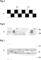
- the Figures 4 to 7 show different versions of optical tracks 4.
- Figure 4 shows an embodiment of the optical track 4, which has a translation-invariant contrast pattern, which is formed by two adjacent strips 10a, 10b, each of which has a constant width along the longitudinal axis of the optical track 4.
- the stripes 10a, 10b forming the contrast pattern generally have a different reflectivity behavior, so that a contrast transition, that is to say an abrupt change in contrast, is obtained along the dividing line of the stripes 10a, 10b, which forms an intrinsic contrast pattern that is associated with the optical sensor 3 regardless of the nature of the surface.
- the strips 10a, 10b can have a very different contrast behavior, in which the first strip 10a forms a black surface and the second strip 10b forms a white surface.
- the strips 10a, 10b can also be formed from different colors.
- Figure 5 shows an embodiment of the optical track 4, which consists of an alternating sequence of different contrast pattern elements 11a, 11b.
- the first contrast pattern element 11a consists of a white field on a first side of the optical track 4 and a black field of the same area on the second side of the optical track 4.
- the second contrast pattern element 11b consists of a black field on the first side of the optical track 4 and an identical white field on the second side of the optical track 4.
- the contrast pattern elements 11a, 11b thus complement one another to form a checkerboard pattern, which can alternatively consist of fields of different colors.
- an intrinsic contrast pattern is given, which can be reliably detected regardless of the reflective properties of the background, thereby enabling the vehicle 2 to be guided safely.
- the optical track 4 according to Figure 5 used as an incremental track by continuously determining the contrast pattern elements 11a, 11b of the optical track 4 when the vehicle 2 is traveling with the optical sensor 3.
- the optical sensor 3 with the optical track 4 forms an incremental encoder for determining the relative position of the vehicle 2.
- the speed of the vehicle 2 can also be determined by evaluating the time sequence when the contrast pattern elements 11a, 11b are detected.
- a slip control can be carried out by controlling the contrast pattern elements 11a, 11b. This is the case if the position of the vehicle 2 is detected by means of an autometric method by detecting the revolutions of the wheels, whereby this position detection can be falsified by the wheels slipping.
- Figure 6 shows an extension of the embodiment of the optical track 4 consisting of the two strips 10a, 10b.
- codes 12 are provided at predetermined positions of the optical track 4. Their absolute positions can be encoded in the codes 12, so that the absolute position of the vehicle 2 can be determined by reading the codes 12 by means of the optical sensor 3.
- 12 tracking information can be coded in the codes, which can also be programmed user-specifically. Examples of such guidance information are information about a switch of the optical track 4. A stop for the vehicle 2 can also be encoded with it.
- Figure 7 shows a further embodiment of the optical track 4.
- This optical track 4 has two outer strips 13a, 13b, which can have different contrasts, in particular also different colors. Between the strips 13a, 13b there is a code track 14 with a continuous, location-dependent varying code 12, in which position information and / or tracking information can be encoded.
Landscapes
- Physics & Mathematics (AREA)
- General Physics & Mathematics (AREA)
- Engineering & Computer Science (AREA)
- Mechanical Engineering (AREA)
- Control Of Position, Course, Altitude, Or Attitude Of Moving Bodies (AREA)
- Length Measuring Devices By Optical Means (AREA)
Abstract
Description
- Die Erfindung betrifft eine Sensoranordnung.
- Derartige Sensoranordnungen bilden generell optische Spurführungssysteme aus, mittels derer eine kontrollierte Bewegung eines Fahrzeugs entlang einer definierten Bahn bewerkstelligt werden kann. Der optische Sensor ist dabei auf dem Fahrzeug montiert. Mit dem optischen Sensor wird eine sich entlang der Bahn des Fahrzeugs erstreckende Spur erfasst, die insbesondere in Form eines eine bestimmte Farbe aufweisenden Streifens ausgebildet, der auf einem Untergrund, insbesondere der Fahrbahn, auf welcher das Fahrzeug fährt, aufgebracht ist. Durch diese Erfassung der Spur wird das Fahrzeug entlang der vorgegebenen Bahn geführt, indem der optische Sensor während der Fahrt des Fahrzeugs fortlaufend Ausgangssignale generiert, die angeben, ob die Spur erfasst wird oder nicht.
- Je nach Einsatzbereich wird der die Spur bildende Streifen auf einem Hallenboden einer Fabrikhalle oder sogar im Außenbereich einer Industrieanlage aufgebracht, beispielsweise durch Aufkleben des Streifens oder durch Aufsprühen einer entsprechenden Farbe.
- Ein Problem derartiger Systeme besteht darin, dass in größeren Hallen oder Anlagen der Untergrund hinsichtlich der Beschaffenheit und hinsichtlich der Farbe variieren kann. Dies kann dazu führen, dass sich in einigen Bereichen der Untergrund farblich oder kontrastmäßig nur noch schwach von dem die Spur bildenden Streifen unterscheidet. Dies kann dazu führen, dass die Spur vom optischen Sensor nicht mehr sicher erfasst werden kann, wodurch keine sichere Spurführung des Fahrzeugs mehr möglich ist.
- Diesem Problem kann prinzipiell dadurch begegnet werden, dass für unterschiedliche Untergründe unterschiedliche Spuren in Form von Streifen ausgewählt werden, deren Farbe einen ausreichenden Kontrast zum Untergrund bildet. Dies ist jedoch äußerst aufwändig.
- Der Erfindung liegt die Aufgabe zugrunde, eine Sensoranordnung der eingangs genannten Art bereitzustellen, welche bei konstruktiv geringem Aufwand eine hohe Funktionalität aufweist.
- Zur Lösung dieser Aufgabe sind die Merkmale des Anspruchs 1 vorgesehen. Vorteilhafte Ausführungsformen und zweckmäßige Weiterbildungen der Erfindung sind in den abhängigen Ansprüchen beschrieben.
- Die Erfindung betrifft eine Sensoranordnung mit einem optischen Sensor, welcher an einem Fahrzeug angeordnet ist. Das Fahrzeug wird entlang einer vorgegebenen Bahn bewegt. Die Bahnkurve ist durch eine auf einem stationären Untergrund aufgebrachte optische Spur gekennzeichnet, wobei die optische Spur ein sich über deren Länge erstreckendes Kontrastmuster aufweist. Der optische Sensor erfasst das Kontrastmuster der optischen Spur während der Fahrt des Fahrzeugs.
- Ein wesentlicher Vorteil der Erfindung besteht darin, dass die optische Spur ein intrinsisches Kontrastmuster aufweist, das heißt ein Kontrastmuster, das Kontrastunterschiede innerhalb der Spur ausbildet, die somit vom optischen Sensor sicher erfasst werden können und zwar unabhängig von der Beschaffenheit des Untergrunds, auf welchem die optische Spur aufgebracht ist. Das Kontrastmuster der optischen Spur kann damit unabhängig von den optischen Eigenschaften des Untergrunds, insbesondere unabhängig von dessen Remissionsgrad, vom optischen Sensor sicher erfasst werden.
- Der optische Sensor generiert dann davon abhängig von der Erfassung der optischen Spur Ausgangssignale, die zur Steuerung des Fahrzeugs verwendet werden können.
- Besonders vorteilhaft ist in Abhängigkeit von mit dem optischen Sensor generierten Ausgangssignalen eine Spurführung des Fahrzeugs durchführbar.
- Der Untergrund, auf der die optische Spur angebracht ist, ist vorteilhaft von der Fahrbahn gebildet, auf der das Fahrzeug fährt. Der optische Sensor ist dann im Bereich der Unterseite des Fahrzeugs so montiert, dass dieser in Abstand oberhalb des Untergrunds angeordnet ist, so dass dieser optische Sensor die optische Spur auf dem Untergrund erfassen kann.
- Je nach Ausbildung des Fahrzeugs und der Umgebung des Fahrzeugs, kann der Untergrund auch von einer Hallendecke oder dergleichen gebildet sein. Dann kann der optische Sensor an der Oberseite des Fahrzeugs angeordnet sein, um die optische Spur zu erfassen.
- Im einfachsten Fall ist das Kontrastmuster in Längsrichtung der optischen Spur unveränderlich ausgebildet.
- Das Kontrastmuster ist damit in Längsrichtung der optischen Spur translationsinvariant ausgebildet. Eine derartige optische Spur ist äußerst einfach aufgebaut und kann dementsprechend einfach hergestellt werden.
- Ein Beispiel für eine derartige optische Spur ist, dass das Kontrastmuster von zwei nebeneinander liegenden, sich in Längsrichtung der optischen Spur erstreckenden Streifen mit unterschiedlichen Remissionen gebildet ist.
- Dieses Kontrastmuster weist eine besonders einfache Struktur auf. Durch die beiden in Längsrichtung der optischen Spur verlaufenden Streifen mit unterschiedlichen Remissionen wird am Übergang zwischen den beiden Streifen ein Kontrastunterschied erhalten, der mit dem optischen Sensor einfach und sicher erfasst werden kann. Wesentlich dabei ist, dass dieser Kontrastunterschied nicht an einem der längsseitigen Ränder der optischen Spur sondern in deren zentralen Bereich liegt. Damit wirken sich Einflüsse der Remission des Untergrunds, unabhängig ob dieser stark oder schwach reflektierend ist, bei der Detektion des Übergangs zwischen den zwei Streifen nicht störend aus, so dass das Kontrastmuster unabhängig von der Beschaffenheit des Untergrunds sicher erfasst werden kann.
- Generell weist das Kontrastmuster der optischen Spur ein Kontrastmuster aus, das im inneren Bereich der optischen Spur Kontrastunterschiede ausbildet, die dann mit dem optischen Sensor unabhängig vom Untergrund erfasst werden können.
- Dies gilt insbesondere auch für eine Ausgestaltung der Erfindung, bei welcher das Kontrastmuster in Längsrichtung der optischen Spur variabel ausgebildet ist.
- Die optische Spur weist somit ein positionsabhängiges Kontrastmuster auf.
- Insbesondere besteht das Kontrastmuster aus einer Folge von in Längsrichtung der optischen Spur hintereinander angeordneten unterschiedlichen Kontrastmusterelementen.
- Diese Kontrastmusterelemente können eine periodische Folge bilden, wobei die Anzahl unterschiedlicher Kontrastmusterelemente in einer Periode unterschiedlich ausgebildet sein kann.
- Generell sind auch aperiodische Anordnungen von Kontrastmusterelementen möglich.
- Für eine sichere Detektion des Kontrastmusters ist es wesentlich, dass dessen Kontrastelemente einen möglichst großen Kontrast aufweisen. Dies wird vorteilhaft dadurch erreicht, dass helle Kontrastelemente sich von dunklen Kontrastelementen deutlich dadurch unterscheiden, dass diese aus reflektierenden Materialien bestehen. Unter reflektierenden Materialien werden Materialien verstanden, die einfallendes Licht in einem engen Winkelbereich zurückreflektieren, der breiter als bei spiegelnden Objekten, jedoch erheblich schmaler als bei diffus reflektierenden Objekten ist. Ein typisches Beispiel für derartige reflektierende Materialien sind retroreflektierende Materialien.
- Als Qualitätsmerkmal für das Kontrastmuster können für die hellen und dunklen Kontrastelemente anhand des zurückreflektierten Lichts im optischen Sensor die Extremwerte der Lichtmengen oder daraus statistisch abgeleitete Größen bestimmt werden und an die Steuerung des Fahrzeugs ausgegeben werden.
- Optische Spuren mit derartigen Folgen von Kontrastmusterelementen können für eine Spurführung des Fahrzeugs verwendet werden.
- Darüber hinaus kann die optische Spur auch als Inkrementalspur genutzt werden, das heißt der optische Sensor mit der optischen Spur bilden einen Inkrementalgeber. Durch ein fortlaufendes Erfassen der Kontrastmusterelemente der optischen Spur mit dem optischen Sensor kann eine Information über die Relativposition des Fahrzeugs erhalten werden. Durch Referenzierung auf einen vorgegebenen Bezugspunkt kann somit die Fahrzeugposition des optischen Sensors bestimmt werden.
- Weiterhin kann aus der zeitaufgelösten Erfassung der Kontrastmusterelemente der optischen Spur mit dem optischen Sensor die Geschwindigkeit des Fahrzeugs ermittelt werden, beziehungsweise die Geschwindigkeit des Fahrzeugs kontrolliert werden.
- Weiterhin ist mit dem optischen Sensor eine Schlupfkontrolle durchführbar.
- Typischerweise wird bei dem Fahrzeug dessen Position nach der Methode der Autometrie bestimmt, das heißt es wird aus der Anzahl der Umdrehungen der Räder die Fahrzeugposition bestimmt. Bei Auftreten eines Schlupfs der Räder ist diese Positionsbestimmung fehlerhaft. Durch eine fortlaufende Erfassung der Kontrastmusterelemente des Kontrastmusters der optischen Spur kann eine Schlupfkontrolle durchgeführt werden, das heißt die Fehler der Positionsbestimmung aufgrund des vorhandenen Schlupfs können korrigiert werden.
- Schließlich ist durch die Erfassung des Kontrastmusters die Winkellage des optischen Sensors relativ zur optischen Spur bestimmt.
- Durch die Erfassung des Kontrastmusters wird mit dem optischen Sensor fortlaufend dessen Winkellage zur optischen Spur, das heißt der Winkel zwischen einer Achse des optischen Sensors zur Achse der optischen Spur bestimmt. Da der optische Sensor fest mit dem Fahrzeug verbunden ist, wird dadurch der aktuelle Winkel zwischen der Achse des Fahrzeugs und der optischen Spur bestimmt. Bei Kurvenfahrten oder bei Wiederanfahren des Fahrzeugs, zum Beispiel nach einem Stromausfall, liefert diese Winkelinformation eine wichtige Zusatzinformation für die Steuerung des Fahrzeugs, beispielsweise um den Lenkeinschlag des Fahrzeugs zu optimieren. Befindet sich beispielsweise die optische Spur in der Mitte des Fahrzeugs beziehungsweise des optischen Sensors, wird jedoch ein von 90° abweichender Winkel zwischen optischem Sensor und optischer Spur detektiert, kann die Lenkung des Fahrzeugs so eingeschlagen werden, dass bei einer Weiterfahrt des Fahrzeugs eine Vergrößerung der Abweichung von der optischen Spur vermieden wird.
- Die Funktionalität der erfindungsgemäßen Sensoranordnung kann dadurch erweitert werden, dass auf der optischen Spur Codes angebracht sind, welche mittels des optischen Sensors gelesen werden.
- Durch Lesen der Codes können weitere Informationen für die Steuerung des Fahrzeugs gewonnen werden.
- Gemäß einer ersten Ausgestaltung sind in den Codes Positionsinformationen kodiert.
- Diese Positionsinformationen können insbesondere die Absolutpositionen des aufgebrachten Codes enthalten, so dass durch Lesen der Codes eine Bestimmung der Absolutposition des Fahrzeugs möglich ist.
- Alternativ oder zusätzlich können in den Codes Spurführungsinformationen kodiert sein.
- Derartige Spurinformationen können Informationen derart enthalten, dass sie eine Weiche oder Haltestelle für das Fahrzeug kodieren. Auch können die Codes frei programmiert werden, um so Zusatzinformationen über die Spurführung des Fahrzeugs vorzugeben.
- Der optische Sensor arbeitet generell nach dem Lichttasterprinzip und weist hierfür wenigstens einen Sendelichtstrahlen emittierenden Sender und wenigstens einen Empfangslichtstrahlen empfangenden Empfänger auf. Generell ist der optische Sensor dabei derart ausgebildet, dass mit diesem ortsaufgelöst Kontrastunterschiede erfasst werden können, so dass mit diesem die Kontrastmuster der optischen Spur erfasst werden können.
- Gemäß einer ersten Ausgestaltung ist der optische Sensor als Reflexionslichtgitter ausgebildet, das heißt der optische Sensor weist eine Linearanordnung mehrerer Lichttaster mit jeweils einem Sendelichtstrahlen emittierenden Sender und einem Empfangslichtstrahlen empfangenden Empfänger auf.
- Gemäß einer alternativen Ausgestaltung weist der optische Sensor als Empfänger einen Bildsensor auf, der in Form einer zeilen- oder matrixförmigen Anordnung von Empfangselementen ausgebildet ist. Insbesondere in dieser Ausgestaltung kann der optische Sensor als Codeleser ausgebildet sein, um auf der optischen Spur angeordnete Codes erfassen können.
- Die Erfindung wird im Folgenden anhand der Zeichnungen erläutert. Es zeigen:
- Figur 1:
- Schematische Darstellung der erfindungsgemäßen Sensoranordnung zur Spurführung eines Fahrzeugs.
- Figur 2:
- Erstes Ausführungsbeispiel des optischen Sensors der Sensoranordnung gemäß
Figur 1 .- a) Draufsicht
- b) Querschnittsdarstellung
- Figur 3:
- Zweites Ausführungsbeispiel des optischen Sensors der Sensoranordnung gemäß
Figur 1 . - Figur 4:
- Erstes Ausführungsbeispiel einer optischen Spur für die Sensoranordnung gemäß
Figur 1 . - Figur 5:
- Zweites Ausführungsbeispiel einer optischen Spur für die Sensoranordnung gemäß
Figur 1 . - Figur 6:
- Drittes Ausführungsbeispiel einer optischen Spur für die Sensoranordnung gemäß
Figur 1 . - Figur 7:
- Viertes Ausführungsbeispiel einer optischen Spur für die Sensoranordnung gemäß
Figur 1 . -
Figur 1 zeigt schematisch ein Ausführungsbeispiel der erfindungsgemäßen Sensoranordnung 1, welches für eine Spurführung eines Fahrzeugs 2 eingesetzt wird. Die Sensoranordnung 1 weist einen optischen Sensor 3 auf, der im vorliegenden Fall an der Frontseite des Fahrzeugs 2 so montiert ist, dass der Erfassungsbereich des optischen Sensors 3, in welchem Objekte oder Objektstrukturen erfasst werden können, auf einen Untergrund gerichtet ist, der als Fahrbahn für das Fahrzeug 2 dient. Der Untergrund kann aus einem Boden einer Halle oder allgemein einer industriellen Anlage gebildet sein. - Auf dem Untergrund ist eine optische Spur 4 als weiteres Bestandteil der Sensoranordnung 1 angeordnet. Die optische Spur 4 kann in Form eines Bands ausgebildet sein, das auf dem Untergrund fixiert wird, beispielsweise durch Klebeverbindungen.
- Die
Figuren 2a und 2b zeigen ein erstes Ausführungsbeispiel des optischen Sensors 3 der Sensoranordnung 1 gemäßFigur 1 . Der optische Sensor 3 ist im vorliegenden Fall als Reflexionslichtgitter ausgebildet. Dieser optische Sensor 3 weist eine Linearanordnung von vorzugsweise identisch ausgebildeten Lichttastern auf, die jeweils aus einem Sendelichtstrahlen 5 emittierenden Sender 6 und einem Empfangslichtstrahlen 7 empfangenden Empfänger 8 bestehen. Die Sender 6 können von Leuchtdioden, die Empfänger von Photodioden gebildet sein. Die Lichttaster sind in einem Gehäuse 9 integriert und sind an eine nicht dargestellte Auswerteeinheit angeschlossen, die die Sender 6 steuert und die Empfangssignale auswertet. Die Auswerteeinheit kann von einem Mikroprozessor oder dergleichen gebildet sein. - Zur Detektion der optischen Spur 4, insbesondere der dort enthaltenen intrinsischen Kontrastmuster, ist die Längsachse des optischen Sensors 3 quer zur Fahrzeugrichtung des Fahrzeugs 2 orientiert, so dass mit diesem die gesamte Breite der optischen Spur 4 erfasst werden kann.
-
Figur 3 zeigt ein zweites Ausführungsbeispiel des optischen Sensors 3. Dieser optische Sensor 3 weist als Empfänger 8 einen Bildsensor auf, der aus einer matrixförmigen Anordnung von Empfangselementen 8a besteht. Der Bildsensor kann beispielsweise in Form eines CMOS- oder CCD-Arrays ausgebildet sein. - Alternativ kann auch ein zeilenförmiger Bildsensor vorgesehen sein.
- Der optische Sensor 3 gemäß
Figur 3 weist im vorliegenden Fall eine Beleuchtungseinheit in Form eines einzelnen Sendelichtstrahlen 5 emittierenden Senders 6 auf. Alternativ kann auch eine Mehrfachanordnung von Sendern 6 vorgesehen sein. - Analog zur Ausführungsform der
Figur 2 sind die Komponenten des optischen Sensors 3 in einem Gehäuse 9 integriert, insbesondere auch die Auswerteeinheit, die zur Steuerung des oder der Sender 6 und zur Auswertung der Empfangssignale der Empfangselemente 8a des Bildsensors dient. - Insbesondere in der Ausführungsform gemäß
Figur 3 ist der optische Sensor 3 als Codeleser ausgebildet. Hierzu ist in der Auswerteeinheit eine entsprechende Dekodiereinheit implementiert. - Die mit dem optischen Sensor 3 abgetastete optische Spur 4 weist generell ein Kontrastmuster auf, das intrinsisch definierte Kontrastübergänge aufweist, die mittels des optischen Sensors 3 unabhängig von den Remissionseigenschaften erkannt werden können.
- Mit dem optischen Sensor 3 erfolgt somit fortlaufend während der Fahrt des Fahrzeugs 2 eine ortsaufgelöste Erfassung der optischen Spur 4, wobei in Abhängigkeit hiervon der optische Sensor 3 Ausgangssignale generiert, die der Steuerung des Fahrzeugs 2 für eine Spurführung zugeführt werden. Die Ausgangssignale des optischen Sensors 3 können beispielsweise angeben, ob die optische Spur 4 vollständig, teilweise oder gar nicht erfasst wird. Prinzipiell kann der optische Sensor 3 auch Ausgangssignale ausgeben, die die Lage der optischen Spur 4 innerhalb des Erfassungsbereichs des optischen Sensors 3 angeben.
- Die
Figuren 4 bis 7 zeigen unterschiedliche Ausführungen von optischen Spuren 4. -
Figur 4 zeigt eine Ausführungsform der optischen Spur 4, die ein translationsinvariantes Kontrastmuster aufweist, das von zwei nebeneinander liegenden Streifen 10a, 10b gebildet ist, die sich mit jeweils konstanter Breite entlang der Längsachse der optischen Spur 4 erstrecken. - Die das Kontrastmuster bildenden Streifen 10a, 10b weisen generell ein unterschiedliches Remissionsverhalten auf, so dass entlang der Trennlinie der Streifen 10a, 10b ein Kontrastübergang, das heißt ein abrupter Wechsel des Kontrasts erhalten wird, der ein intrinsisches Kontrastmuster ausbildet, das mit dem optischen Sensor 3 unabhängig von der Beschaffenheit des Untergrunds erfasst werden kann. Die Streifen 10a, 10b können ein stark unterschiedliches Kontrastverhalten aufweisen, in dem der erste Streifen 10a eine schwarze Fläche und der zweite Streifen 10b eine weiße Fläche ausbildet. Auch können die Streifen 10a, 10b aus unterschiedlichen Farben gebildet sein.
-
Figur 5 zeigt eine Ausführungsform der optischen Spur 4, die aus einer alternatierenden Folge unterschiedlicher Kontrastmusterelemente 11a, 11b besteht. - Das erste Kontrastmusterelement 11a besteht aus einem weißen Feld auf einer ersten Seite der optischen Spur 4 und einem flächengleichem schwarzen Feld auf der zweiten Seite der optischen Spur 4.
- Das zweite Kontrastmusterelement 11b besteht aus einem schwarzen Feld auf der ersten Seite der optischen Spur 4 und einem flächengleichen weißen Feld auf der zweiten Seite der optischen Spur 4.
- Somit ergänzen sich die Kontrastmusterelemente 11a, 11b zu einem Schachbrettmuster, das alternativ aus Feldern unterschiedlicher Farbe bestehen kann.
- Auch bei der optischen Spur 4 gemäß
Figur 5 ist, ebenso wie die der Ausführungsform gemäßFigur 4 , ein intrinsisches Kontrastmuster gegeben, das unabhängig von den Remissionseigenschaften des Untergrunds sicher detektiert werden kann, wodurch eine sichere Spurführung des Fahrzeugs 2 ermöglicht wird. - Weiterhin wird die optische Spur 4 gemäß
Figur 5 als Inkrementalspur genutzt, indem bei der Fahrt des Fahrzeugs 2 mit dem optischen Sensor 3 fortlaufend die Kontrastmusterelemente 11a, 11b der optischen Spur 4 bestimmt werden. Dadurch bildet der optische Sensor 3 mit der optischen Spur 4 einen Inkrementalgeber zur Bestimmung der Relativposition des Fahrzeugs 2. - Durch die Auswertung der zeitlichen Abfolge bei der Detektion der Kontrastmusterelemente 11a, 11b kann außerdem die Geschwindigkeit des Fahrzeugs 2 bestimmt werden.
- Schließlich kann durch eine Steuerung der Kontrastmusterelemente 11a, 11b eine Schlupfkontrolle durchgeführt werden. Dies ist dann der Fall, wenn mittels eines Autometrieverfahrens durch die Erfassung der Umdrehungen der Räder die Position des Fahrzeugs 2 erfasst wird, wobei diese Positionserfassung durch einen Schlupf der Räder verfälscht sein kann.
-
Figur 6 zeigt eine Erweiterung der Ausführungsform der optischen Spur 4 bestehend aus den beiden Streifen 10a, 10b. In diesem Fall sind an vorgegebenen Positionen der optischen Spur 4 Codes 12 vorgesehen. In den Codes 12 können deren Absolutpositionen kodiert sein, so dass durch Lesen der Codes 12 mittels des optischen Sensors 3 die Absolutposition des Fahrzeugs 2 bestimmt werden kann. Weiterhin können in den Codes 12 Spurführungsinformationen kodiert sein, wobei diese auch anwenderspezifisch programmiert werden können. Beispiele für derartige Spurführungsinformationen sind Informationen über eine Weiche der optischen Spur 4. Auch kann damit eine Haltestelle für das Fahrzeug 2 kodiert sein. -
Figur 7 zeigt eine weitere Ausführungsform der optischen Spur 4. Diese optische Spur 4 weist zwei äußere Streifen 13a, 13b auf, die unterschiedliche Kontraste, insbesondere auch unterschiedliche Farbgebungen aufweisen können. Zwischen den Streifen 13a, 13b befindet sich eine Codespur 14 mit einem fortlaufenden, ortsabhängig variierendem Code 12, in dem Positionsinformationen und/oder Spurführungsinformationen kodiert sein können. -
- (1)
- Sensoranordnung
- (2)
- Fahrzeug
- (3)
- Optischer Sensor
- (4)
- Optische Spur
- (5)
- Sendelichtstrahlen
- (6)
- Sender
- (7)
- Empfangslichtstrahlen
- (8)
- Empfänger
- (8a)
- Empfangselemente
- (9)
- Gehäuse
- (10a)
- Streifen
- (10b)
- Streifen
- (11a)
- Kontrastmusterelement
- (11b)
- Kontrastmusterelement
- (12)
- Code
- (13a)
- Streifen
- (13b)
- Streifen
- (14)
- Codespur
Claims (16)
- Sensoranordnung (1) mit einem optischen Sensor (3), welcher an einem Fahrzeug (2) angeordnet ist, welches entlang einer vorgegebenen Bahn bewegt wird, dadurch gekennzeichnet, dass die Bahnkurve durch eine auf einem stationären Untergrund aufgebrachte optische Spur (4) gekennzeichnet ist, wobei die optische Spur (4) ein sich über deren Länge erstreckendes Kontrastmuster aufweist, und dass der optische Sensor (3) das Kontrastmuster der optischen Spur (4) während der Fahrt des Fahrzeugs (2) erfasst.
- Sensoranordnung (1) nach Anspruch 1, dadurch gekennzeichnet, dass in Abhängigkeit von mit dem optischen Sensor (3) generierten Ausgangssignalen eine Spurführung des Fahrzeugs (2) durchführbar ist.
- Sensoranordnung (1) nach einem der Ansprüche 1 oder 2, dadurch gekennzeichnet, dass das Kontrastmuster in Längsrichtung der optischen Spur (4) unveränderlich ausgebildet ist.
- Sensoranordnung (1) nach Anspruch 3, dadurch gekennzeichnet, dass das Kontrastmuster von zwei nebeneinander liegenden, sich in Längsrichtung der optischen Spur (4) erstreckenden Streifen (10a, 10b) mit unterschiedlichen Remissionen gebildet ist.
- Sensoranordnung (1) nach einem der Ansprüche 1 oder 2, dadurch gekennzeichnet, dass das Kontrastmuster in Längsrichtung der optischen Spur (4) variabel ausgebildet ist.
- Sensoranordnung (1) nach Anspruch 5, dadurch gekennzeichnet, dass das Kontrastmuster aus einer Folge von in Längsrichtung der optischen Spur (4) hintereinander angeordneten unterschiedlichen Kontrastmusterelementen (11a, 11b) besteht.
- Sensoranordnung (1) nach einem der Ansprüche 5 oder 6, dadurch gekennzeichnet, dass durch Erfassung der variablen Kontrastmuster der optischen Spur (4) mittels des optischen Sensors (3) eine Geschwindigkeitskontrolle des Fahrzeugs (2) durchführbar ist.
- Sensoranordnung (1) nach einem der Ansprüche 5 - 7, dadurch gekennzeichnet, dass die optische Spur (4) eine Inkrementalspur ausbildet.
- Sensoranordnung (1) nach einem der Ansprüche 4 - 8, dadurch gekennzeichnet, dass mit dem optischen Sensor (3) eine Schlupfkontrolle durchführbar ist.
- Sensoranordnung (1) nach einem der Ansprüche 1 - 9, dadurch gekennzeichnet, dass durch die Erfassung des Kontrastmusters die Winkellage des optischen Sensors (3) relativ zur optischen Spur (4) bestimmt ist.
- Sensoranordnung (1) nach einem der Ansprüche 1 - 10, dadurch gekennzeichnet, dass auf der optischen Spur (4) Codes (12) angebracht sind, welche mittels des optischen Sensors (3) gelesen werden.
- Sensoranordnung (1) nach Anspruch 11, dadurch gekennzeichnet, dass in den Codes (12) Positionsinformationen kodiert sind.
- Sensoranordnung (1) nach einem der Ansprüche 11 oder 12, dadurch gekennzeichnet, dass in den Codes (12) Spurführungsinformationen kodiert sind.
- Sensoranordnung (1) nach einem der Ansprüche 1 - 13, dadurch gekennzeichnet, dass der optische Sensor (3) nach dem Lichttasterprinzip arbeitet.
- Sensoranordnung (1) nach Anspruch 14, dadurch gekennzeichnet, dass der optische Sensor (3) einen Bildsensor aufweist, oder dass der optische Sensor (3) in Form eines Reflexionslichtgitters ausgebildet ist.
- Sensoranordnung (1) nach einem der Ansprüche 1 - 15, dadurch gekennzeichnet, dass der optische Sensor (3) ein Codeleser ist.
Priority Applications (1)
| Application Number | Priority Date | Filing Date | Title |
|---|---|---|---|
| EP19151358.9A EP3680624B2 (de) | 2019-01-11 | 2019-01-11 | Sensoranordnung |
Applications Claiming Priority (1)
| Application Number | Priority Date | Filing Date | Title |
|---|---|---|---|
| EP19151358.9A EP3680624B2 (de) | 2019-01-11 | 2019-01-11 | Sensoranordnung |
Publications (3)
| Publication Number | Publication Date |
|---|---|
| EP3680624A1 true EP3680624A1 (de) | 2020-07-15 |
| EP3680624B1 EP3680624B1 (de) | 2022-09-07 |
| EP3680624B2 EP3680624B2 (de) | 2025-12-24 |
Family
ID=65019366
Family Applications (1)
| Application Number | Title | Priority Date | Filing Date |
|---|---|---|---|
| EP19151358.9A Active EP3680624B2 (de) | 2019-01-11 | 2019-01-11 | Sensoranordnung |
Country Status (1)
| Country | Link |
|---|---|
| EP (1) | EP3680624B2 (de) |
Citations (5)
| Publication number | Priority date | Publication date | Assignee | Title |
|---|---|---|---|---|
| EP1345031A2 (de) * | 2002-03-16 | 2003-09-17 | Leuze electronic GmbH + Co. | Optoelektronische Vorrichtung |
| EP1621504A1 (de) * | 2004-07-27 | 2006-02-01 | ThyssenKrupp Aufzüge GmbH | Signalband und System zum Bestimmen eines Bewegungszustandes eines bewegten Körpers |
| DE102005047658A1 (de) * | 2005-10-05 | 2007-04-12 | Leuze Electronic Gmbh + Co. Kg | Vorrichtung zur Positionsbestimmung |
| EP3270114A1 (de) * | 2016-07-15 | 2018-01-17 | Leuze electronic GmbH + Co KG | Sensoranordnung |
| EP3282286A1 (de) * | 2016-08-08 | 2018-02-14 | Leuze electronic GmbH + Co KG | Optischer sensor |
Family Cites Families (9)
| Publication number | Priority date | Publication date | Assignee | Title |
|---|---|---|---|---|
| US2996137A (en) * | 1958-01-29 | 1961-08-15 | Chu Yaohan | Automatic radar guided and computer controlled vehicles |
| JPH0480409A (ja) * | 1990-07-23 | 1992-03-13 | Komatsu Ltd | 路面へのマーキングとその検出方法 |
| DE10013767A1 (de) | 2000-03-20 | 2001-10-11 | Rosenheimer Foerderanlage | Bodentransportsystem mit einem Versorgungs- und Leitsystem zur berührungslosen Energieübertragung und berührungslosen Führung von Elektrotransportfahrzeugen |
| DE102006027325A1 (de) | 2006-06-13 | 2007-12-20 | Robert Bosch Gmbh | Spurhalteassistent mit Spurwechselfunktion |
| EP2037225B1 (de) | 2007-09-12 | 2011-08-31 | Pepperl + Fuchs GmbH | Verfahren und Vorrichtung zum Bestimmen der Position eines Fahrzeugs, Computerprogramm und Computerprogrammprodukt |
| US9180908B2 (en) | 2010-11-19 | 2015-11-10 | Magna Electronics Inc. | Lane keeping system and lane centering system |
| KR101284897B1 (ko) * | 2012-02-20 | 2013-07-10 | 한국철도기술연구원 | 절대위치검지시스템 |
| JP2015020719A (ja) | 2013-07-23 | 2015-02-02 | 株式会社デンソー | 車線維持支援装置 |
| DE202014100689U1 (de) * | 2014-02-17 | 2015-06-01 | Sick Ag | Optoelektronische Vorrichtung zur Positionsbestimmung |
-
2019
- 2019-01-11 EP EP19151358.9A patent/EP3680624B2/de active Active
Patent Citations (5)
| Publication number | Priority date | Publication date | Assignee | Title |
|---|---|---|---|---|
| EP1345031A2 (de) * | 2002-03-16 | 2003-09-17 | Leuze electronic GmbH + Co. | Optoelektronische Vorrichtung |
| EP1621504A1 (de) * | 2004-07-27 | 2006-02-01 | ThyssenKrupp Aufzüge GmbH | Signalband und System zum Bestimmen eines Bewegungszustandes eines bewegten Körpers |
| DE102005047658A1 (de) * | 2005-10-05 | 2007-04-12 | Leuze Electronic Gmbh + Co. Kg | Vorrichtung zur Positionsbestimmung |
| EP3270114A1 (de) * | 2016-07-15 | 2018-01-17 | Leuze electronic GmbH + Co KG | Sensoranordnung |
| EP3282286A1 (de) * | 2016-08-08 | 2018-02-14 | Leuze electronic GmbH + Co KG | Optischer sensor |
Also Published As
| Publication number | Publication date |
|---|---|
| EP3680624B1 (de) | 2022-09-07 |
| EP3680624B2 (de) | 2025-12-24 |
Similar Documents
| Publication | Publication Date | Title |
|---|---|---|
| DE69001657T2 (de) | Optische kodierer. | |
| EP1407231B1 (de) | Positionsmesseinrichtung | |
| EP2667218B1 (de) | Energiespar-3-D-Sensor | |
| EP3809157A1 (de) | Entfernungsmessender optoelektronischer sensor und verfahren zur erfassung eines zielobjekts | |
| DE4243778A1 (de) | Vorrichtung oder Verfahren zur Lageerkennung | |
| DE3221621A1 (de) | Stellungsgeber fuer antriebsanlagen, insbesondere von fahrzeugen | |
| EP0377097A1 (de) | Lenkwinkelsensor für ein Kraftfahrzeug | |
| EP1035044A2 (de) | Vorrichtung zur Positionierung eines Fahrzeugs | |
| EP3058240A1 (de) | Kupplungssensorsystem | |
| DE102014102049A1 (de) | Optoelektronischer Sensor und Verfahren zur Erfassung von Objekten in einem Überwachungsbereich | |
| EP3401702A1 (de) | Sensorsystem | |
| DE19638911B4 (de) | Drehwinkelsensor mit integrierter Umdrehungserkennung | |
| DE202014100712U1 (de) | Optoelektronischer Sensor zur Erfassung von Objekten in einem Überwachungsbereich | |
| DE102021102053B4 (de) | Bestimmung einer Position | |
| DE102017100962A1 (de) | Sensoranordnung | |
| EP3680624B2 (de) | Sensoranordnung | |
| DE20118145U1 (de) | Optischer Sensor | |
| EP1740910B1 (de) | Drehsteller | |
| DE202018105438U1 (de) | Optischer Sensor | |
| DE102020118639B3 (de) | Codeelemente einer Maßverkörperung einer Gebervorrichtung | |
| DE102018127676B4 (de) | Optoelektronischer Sensor | |
| DE102009005536A1 (de) | Drehwinkelsensor | |
| DE19918313A1 (de) | Winkelsensor | |
| EP0973013B1 (de) | Wegsensor | |
| DE3203720A1 (de) | Geraet zur erkennung von auf gegenstaenden angebrachten optischen codemarken |
Legal Events
| Date | Code | Title | Description |
|---|---|---|---|
| PUAI | Public reference made under article 153(3) epc to a published international application that has entered the european phase |
Free format text: ORIGINAL CODE: 0009012 |
|
| STAA | Information on the status of an ep patent application or granted ep patent |
Free format text: STATUS: REQUEST FOR EXAMINATION WAS MADE |
|
| 17P | Request for examination filed |
Effective date: 20190925 |
|
| AK | Designated contracting states |
Kind code of ref document: A1 Designated state(s): AL AT BE BG CH CY CZ DE DK EE ES FI FR GB GR HR HU IE IS IT LI LT LU LV MC MK MT NL NO PL PT RO RS SE SI SK SM TR |
|
| AX | Request for extension of the european patent |
Extension state: BA ME |
|
| STAA | Information on the status of an ep patent application or granted ep patent |
Free format text: STATUS: EXAMINATION IS IN PROGRESS |
|
| 17Q | First examination report despatched |
Effective date: 20210223 |
|
| GRAP | Despatch of communication of intention to grant a patent |
Free format text: ORIGINAL CODE: EPIDOSNIGR1 |
|
| STAA | Information on the status of an ep patent application or granted ep patent |
Free format text: STATUS: GRANT OF PATENT IS INTENDED |
|
| RIC1 | Information provided on ipc code assigned before grant |
Ipc: B61L 25/02 20060101ALI20220513BHEP Ipc: B61L 23/04 20060101ALI20220513BHEP Ipc: G01D 5/249 20060101ALI20220513BHEP Ipc: G01D 5/245 20060101AFI20220513BHEP |
|
| INTG | Intention to grant announced |
Effective date: 20220531 |
|
| GRAS | Grant fee paid |
Free format text: ORIGINAL CODE: EPIDOSNIGR3 |
|
| GRAA | (expected) grant |
Free format text: ORIGINAL CODE: 0009210 |
|
| STAA | Information on the status of an ep patent application or granted ep patent |
Free format text: STATUS: THE PATENT HAS BEEN GRANTED |
|
| AK | Designated contracting states |
Kind code of ref document: B1 Designated state(s): AL AT BE BG CH CY CZ DE DK EE ES FI FR GB GR HR HU IE IS IT LI LT LU LV MC MK MT NL NO PL PT RO RS SE SI SK SM TR |
|
| REG | Reference to a national code |
Ref country code: GB Ref legal event code: FG4D Free format text: NOT ENGLISH |
|
| REG | Reference to a national code |
Ref country code: CH Ref legal event code: EP Ref country code: AT Ref legal event code: REF Ref document number: 1517407 Country of ref document: AT Kind code of ref document: T Effective date: 20220915 |
|
| REG | Reference to a national code |
Ref country code: DE Ref legal event code: R096 Ref document number: 502019005526 Country of ref document: DE |
|
| REG | Reference to a national code |
Ref country code: IE Ref legal event code: FG4D Free format text: LANGUAGE OF EP DOCUMENT: GERMAN |
|
| REG | Reference to a national code |
Ref country code: LT Ref legal event code: MG9D |
|
| REG | Reference to a national code |
Ref country code: NL Ref legal event code: MP Effective date: 20220907 |
|
| PG25 | Lapsed in a contracting state [announced via postgrant information from national office to epo] |
Ref country code: SE Free format text: LAPSE BECAUSE OF FAILURE TO SUBMIT A TRANSLATION OF THE DESCRIPTION OR TO PAY THE FEE WITHIN THE PRESCRIBED TIME-LIMIT Effective date: 20220907 Ref country code: RS Free format text: LAPSE BECAUSE OF FAILURE TO SUBMIT A TRANSLATION OF THE DESCRIPTION OR TO PAY THE FEE WITHIN THE PRESCRIBED TIME-LIMIT Effective date: 20220907 Ref country code: NO Free format text: LAPSE BECAUSE OF FAILURE TO SUBMIT A TRANSLATION OF THE DESCRIPTION OR TO PAY THE FEE WITHIN THE PRESCRIBED TIME-LIMIT Effective date: 20221207 Ref country code: LV Free format text: LAPSE BECAUSE OF FAILURE TO SUBMIT A TRANSLATION OF THE DESCRIPTION OR TO PAY THE FEE WITHIN THE PRESCRIBED TIME-LIMIT Effective date: 20220907 Ref country code: LT Free format text: LAPSE BECAUSE OF FAILURE TO SUBMIT A TRANSLATION OF THE DESCRIPTION OR TO PAY THE FEE WITHIN THE PRESCRIBED TIME-LIMIT Effective date: 20220907 Ref country code: FI Free format text: LAPSE BECAUSE OF FAILURE TO SUBMIT A TRANSLATION OF THE DESCRIPTION OR TO PAY THE FEE WITHIN THE PRESCRIBED TIME-LIMIT Effective date: 20220907 |
|
| PG25 | Lapsed in a contracting state [announced via postgrant information from national office to epo] |
Ref country code: HR Free format text: LAPSE BECAUSE OF FAILURE TO SUBMIT A TRANSLATION OF THE DESCRIPTION OR TO PAY THE FEE WITHIN THE PRESCRIBED TIME-LIMIT Effective date: 20220907 Ref country code: GR Free format text: LAPSE BECAUSE OF FAILURE TO SUBMIT A TRANSLATION OF THE DESCRIPTION OR TO PAY THE FEE WITHIN THE PRESCRIBED TIME-LIMIT Effective date: 20221208 |
|
| PG25 | Lapsed in a contracting state [announced via postgrant information from national office to epo] |
Ref country code: SM Free format text: LAPSE BECAUSE OF FAILURE TO SUBMIT A TRANSLATION OF THE DESCRIPTION OR TO PAY THE FEE WITHIN THE PRESCRIBED TIME-LIMIT Effective date: 20220907 Ref country code: RO Free format text: LAPSE BECAUSE OF FAILURE TO SUBMIT A TRANSLATION OF THE DESCRIPTION OR TO PAY THE FEE WITHIN THE PRESCRIBED TIME-LIMIT Effective date: 20220907 Ref country code: PT Free format text: LAPSE BECAUSE OF FAILURE TO SUBMIT A TRANSLATION OF THE DESCRIPTION OR TO PAY THE FEE WITHIN THE PRESCRIBED TIME-LIMIT Effective date: 20230109 Ref country code: ES Free format text: LAPSE BECAUSE OF FAILURE TO SUBMIT A TRANSLATION OF THE DESCRIPTION OR TO PAY THE FEE WITHIN THE PRESCRIBED TIME-LIMIT Effective date: 20220907 Ref country code: CZ Free format text: LAPSE BECAUSE OF FAILURE TO SUBMIT A TRANSLATION OF THE DESCRIPTION OR TO PAY THE FEE WITHIN THE PRESCRIBED TIME-LIMIT Effective date: 20220907 |
|
| PG25 | Lapsed in a contracting state [announced via postgrant information from national office to epo] |
Ref country code: SK Free format text: LAPSE BECAUSE OF FAILURE TO SUBMIT A TRANSLATION OF THE DESCRIPTION OR TO PAY THE FEE WITHIN THE PRESCRIBED TIME-LIMIT Effective date: 20220907 Ref country code: PL Free format text: LAPSE BECAUSE OF FAILURE TO SUBMIT A TRANSLATION OF THE DESCRIPTION OR TO PAY THE FEE WITHIN THE PRESCRIBED TIME-LIMIT Effective date: 20220907 Ref country code: IS Free format text: LAPSE BECAUSE OF FAILURE TO SUBMIT A TRANSLATION OF THE DESCRIPTION OR TO PAY THE FEE WITHIN THE PRESCRIBED TIME-LIMIT Effective date: 20230107 Ref country code: EE Free format text: LAPSE BECAUSE OF FAILURE TO SUBMIT A TRANSLATION OF THE DESCRIPTION OR TO PAY THE FEE WITHIN THE PRESCRIBED TIME-LIMIT Effective date: 20220907 |
|
| REG | Reference to a national code |
Ref country code: DE Ref legal event code: R026 Ref document number: 502019005526 Country of ref document: DE |
|
| PLBI | Opposition filed |
Free format text: ORIGINAL CODE: 0009260 |
|
| PLAX | Notice of opposition and request to file observation + time limit sent |
Free format text: ORIGINAL CODE: EPIDOSNOBS2 |
|
| PG25 | Lapsed in a contracting state [announced via postgrant information from national office to epo] |
Ref country code: NL Free format text: LAPSE BECAUSE OF FAILURE TO SUBMIT A TRANSLATION OF THE DESCRIPTION OR TO PAY THE FEE WITHIN THE PRESCRIBED TIME-LIMIT Effective date: 20220907 Ref country code: AL Free format text: LAPSE BECAUSE OF FAILURE TO SUBMIT A TRANSLATION OF THE DESCRIPTION OR TO PAY THE FEE WITHIN THE PRESCRIBED TIME-LIMIT Effective date: 20220907 |
|
| 26 | Opposition filed |
Opponent name: PEPPERL+FUCHS SE Effective date: 20230607 |
|
| PG25 | Lapsed in a contracting state [announced via postgrant information from national office to epo] |
Ref country code: DK Free format text: LAPSE BECAUSE OF FAILURE TO SUBMIT A TRANSLATION OF THE DESCRIPTION OR TO PAY THE FEE WITHIN THE PRESCRIBED TIME-LIMIT Effective date: 20220907 |
|
| PG25 | Lapsed in a contracting state [announced via postgrant information from national office to epo] |
Ref country code: SI Free format text: LAPSE BECAUSE OF FAILURE TO SUBMIT A TRANSLATION OF THE DESCRIPTION OR TO PAY THE FEE WITHIN THE PRESCRIBED TIME-LIMIT Effective date: 20220907 |
|
| REG | Reference to a national code |
Ref country code: CH Ref legal event code: PL |
|
| GBPC | Gb: european patent ceased through non-payment of renewal fee |
Effective date: 20230111 |
|
| PG25 | Lapsed in a contracting state [announced via postgrant information from national office to epo] |
Ref country code: LU Free format text: LAPSE BECAUSE OF NON-PAYMENT OF DUE FEES Effective date: 20230111 |
|
| REG | Reference to a national code |
Ref country code: BE Ref legal event code: MM Effective date: 20230131 |
|
| PLBB | Reply of patent proprietor to notice(s) of opposition received |
Free format text: ORIGINAL CODE: EPIDOSNOBS3 |
|
| PG25 | Lapsed in a contracting state [announced via postgrant information from national office to epo] |
Ref country code: LI Free format text: LAPSE BECAUSE OF NON-PAYMENT OF DUE FEES Effective date: 20230131 Ref country code: GB Free format text: LAPSE BECAUSE OF NON-PAYMENT OF DUE FEES Effective date: 20230111 Ref country code: CH Free format text: LAPSE BECAUSE OF NON-PAYMENT OF DUE FEES Effective date: 20230131 |
|
| PG25 | Lapsed in a contracting state [announced via postgrant information from national office to epo] |
Ref country code: FR Free format text: LAPSE BECAUSE OF NON-PAYMENT OF DUE FEES Effective date: 20230131 Ref country code: BE Free format text: LAPSE BECAUSE OF NON-PAYMENT OF DUE FEES Effective date: 20230131 |
|
| PG25 | Lapsed in a contracting state [announced via postgrant information from national office to epo] |
Ref country code: IE Free format text: LAPSE BECAUSE OF NON-PAYMENT OF DUE FEES Effective date: 20230111 |
|
| PG25 | Lapsed in a contracting state [announced via postgrant information from national office to epo] |
Ref country code: IT Free format text: LAPSE BECAUSE OF FAILURE TO SUBMIT A TRANSLATION OF THE DESCRIPTION OR TO PAY THE FEE WITHIN THE PRESCRIBED TIME-LIMIT Effective date: 20220907 |
|
| PG25 | Lapsed in a contracting state [announced via postgrant information from national office to epo] |
Ref country code: MC Free format text: LAPSE BECAUSE OF FAILURE TO SUBMIT A TRANSLATION OF THE DESCRIPTION OR TO PAY THE FEE WITHIN THE PRESCRIBED TIME-LIMIT Effective date: 20220907 |
|
| PG25 | Lapsed in a contracting state [announced via postgrant information from national office to epo] |
Ref country code: MC Free format text: LAPSE BECAUSE OF FAILURE TO SUBMIT A TRANSLATION OF THE DESCRIPTION OR TO PAY THE FEE WITHIN THE PRESCRIBED TIME-LIMIT Effective date: 20220907 |
|
| PG25 | Lapsed in a contracting state [announced via postgrant information from national office to epo] |
Ref country code: BG Free format text: LAPSE BECAUSE OF FAILURE TO SUBMIT A TRANSLATION OF THE DESCRIPTION OR TO PAY THE FEE WITHIN THE PRESCRIBED TIME-LIMIT Effective date: 20220907 |
|
| PG25 | Lapsed in a contracting state [announced via postgrant information from national office to epo] |
Ref country code: BG Free format text: LAPSE BECAUSE OF FAILURE TO SUBMIT A TRANSLATION OF THE DESCRIPTION OR TO PAY THE FEE WITHIN THE PRESCRIBED TIME-LIMIT Effective date: 20220907 |
|
| REG | Reference to a national code |
Ref country code: AT Ref legal event code: MM01 Ref document number: 1517407 Country of ref document: AT Kind code of ref document: T Effective date: 20240111 |
|
| PG25 | Lapsed in a contracting state [announced via postgrant information from national office to epo] |
Ref country code: AT Free format text: LAPSE BECAUSE OF NON-PAYMENT OF DUE FEES Effective date: 20240111 |
|
| PG25 | Lapsed in a contracting state [announced via postgrant information from national office to epo] |
Ref country code: CY Free format text: LAPSE BECAUSE OF FAILURE TO SUBMIT A TRANSLATION OF THE DESCRIPTION OR TO PAY THE FEE WITHIN THE PRESCRIBED TIME-LIMIT; INVALID AB INITIO Effective date: 20190111 |
|
| PG25 | Lapsed in a contracting state [announced via postgrant information from national office to epo] |
Ref country code: HU Free format text: LAPSE BECAUSE OF FAILURE TO SUBMIT A TRANSLATION OF THE DESCRIPTION OR TO PAY THE FEE WITHIN THE PRESCRIBED TIME-LIMIT; INVALID AB INITIO Effective date: 20190111 |
|
| P01 | Opt-out of the competence of the unified patent court (upc) registered |
Free format text: CASE NUMBER: UPC_APP_9743_3680624/2025 Effective date: 20251013 |
|
| PUAH | Patent maintained in amended form |
Free format text: ORIGINAL CODE: 0009272 |
|
| STAA | Information on the status of an ep patent application or granted ep patent |
Free format text: STATUS: PATENT MAINTAINED AS AMENDED |
|
| REG | Reference to a national code |
Ref country code: CH Ref legal event code: M12 Free format text: ST27 STATUS EVENT CODE: U-0-0-M10-M12 (AS PROVIDED BY THE NATIONAL OFFICE) Effective date: 20251126 |
|
| PG25 | Lapsed in a contracting state [announced via postgrant information from national office to epo] |
Ref country code: TR Free format text: LAPSE BECAUSE OF FAILURE TO SUBMIT A TRANSLATION OF THE DESCRIPTION OR TO PAY THE FEE WITHIN THE PRESCRIBED TIME-LIMIT Effective date: 20220907 |
|
| 27A | Patent maintained in amended form |
Effective date: 20251224 |
|
| AK | Designated contracting states |
Kind code of ref document: B2 Designated state(s): AL AT BE BG CH CY CZ DE DK EE ES FI FR GB GR HR HU IE IS IT LI LT LU LV MC MK MT NL NO PL PT RO RS SE SI SK SM TR |
|
| REG | Reference to a national code |
Ref country code: DE Ref legal event code: R102 Ref document number: 502019005526 Country of ref document: DE |
|
| PGFP | Annual fee paid to national office [announced via postgrant information from national office to epo] |
Ref country code: DE Payment date: 20260121 Year of fee payment: 8 |
|
| PGFP | Annual fee paid to national office [announced via postgrant information from national office to epo] |
Ref country code: AT Payment date: 20260410 Year of fee payment: 5 |