EP3679988B1 - Feuerdichtung - Google Patents
Feuerdichtung Download PDFInfo
- Publication number
- EP3679988B1 EP3679988B1 EP20150877.7A EP20150877A EP3679988B1 EP 3679988 B1 EP3679988 B1 EP 3679988B1 EP 20150877 A EP20150877 A EP 20150877A EP 3679988 B1 EP3679988 B1 EP 3679988B1
- Authority
- EP
- European Patent Office
- Prior art keywords
- elongate
- housing
- sealing member
- fire seal
- fire
- Prior art date
- Legal status (The legal status is an assumption and is not a legal conclusion. Google has not performed a legal analysis and makes no representation as to the accuracy of the status listed.)
- Active
Links
Images










Classifications
-
- A—HUMAN NECESSITIES
- A62—LIFE-SAVING; FIRE-FIGHTING
- A62C—FIRE-FIGHTING
- A62C3/00—Fire prevention, containment or extinguishing specially adapted for particular objects or places
- A62C3/14—Fire prevention, containment or extinguishing specially adapted for particular objects or places in connection with doors, windows, ventilators, partitions, or shutters, e.g. automatic closing
-
- A—HUMAN NECESSITIES
- A62—LIFE-SAVING; FIRE-FIGHTING
- A62C—FIRE-FIGHTING
- A62C2/00—Fire prevention or containment
- A62C2/06—Physical fire-barriers
- A62C2/24—Operating or controlling mechanisms
- A62C2/241—Operating or controlling mechanisms having mechanical actuators and heat sensitive parts
- A62C2/242—Operating or controlling mechanisms having mechanical actuators and heat sensitive parts with fusible links
Definitions
- This invention concerns a fire seal, and particularly but not exclusively a fire seal selectively engageable between the side edge of a floor panel and a facing wall; and also a fire sealing assembly.
- DE 32 39 177 A1 discloses a fire resisting door, which consists of door body and door case or door frame, at least in the area of one door edge, with an additional closing device which responds to the heat of a fire.
- the closing device contains, as trigger means, a material which changes its state under the effect of heat by expanding, melting, shrinking or by releasing energy, either actively or passively, in another way.
- a bolt is seated on an intumescent cushion of such an expanding material, and, in the event of fire, the bolt is pushed out of the door body and into a recess, thus positively locking door body and door case while at the same time sealing the gap between them. This means that the door body is no longer capable of warping on account of the prior response of the intumescent cushion.
- the closing device may bring about a positive or frictional locking.
- KR 2010 0097997 A discloses a door closing device to prevent components from being damaged when a door is opened and closed and to eliminate noise by eliminating a spring inserted between moving frames.
- the door closing device comprises a protect unit frame and a push frame.
- the protection unit frame comprises a door receiving part for accepting a door and a frame receiving part.
- the push frame is slid along the inner surface of the protection unit frame and is accepted in the frame receiving part during moving.
- the elongate housing may be made of any of steel, aluminium, or calcium silicate.
- the resilient member may comprise one or more compression springs.
- a sealing part may be provided on an outer face of the elongate sealing member.
- the sealing part may comprise any of a brush, vane seal, intumescent seal, or an elongate strip, which strip may be hollow and may be made of silicone or EPDM.
- the fusible restraint may be made of nylon, EPDM, rubber, PVC or metal, and especially an alloy.
- the fusible restraint may comprise a sleeve extending at least partially around the elongate housing and elongate sealing member so as to restrain the elongate sealing member in the inactive position.
- the sleeve may be made of PVC, or the sleeve may be made of a paper material.
- a plurality of resilient members may be provided.
- a guide may be provided, which is locatable inside the helical coil of one of the one or more compression springs, to maintain the alignment of the compression springs.
- the fire seal may further include an extension arrangement for spacing the elongate housing and the elongate sealing member from a mounting point such as a floor panel.
- the extension arrangement may include an elongate spacer for location between the elongate housing and a bracket, wherein the bracket is for mounting to a floor panel, the spacer is mountable to the bracket, and the housing is mountable to the spacer.
- the invention still further provides a fire sealing assembly, the assembly including a fire seal according to any of the preceding paragraphs provided on a side edge of a floor panel and facing towards a wall, with the fire seal configured such that in the inactive position a space is provided between the floor panel and the wall, but in the active position the sealing member engages against the wall to close the space.
- Figs. 1 to 5 show a first fire seal 10 which has an elongate housing 12 in the form of a channel section with inwardly extending lips 14 on an open side.
- An elongate sealing member 16 is provided which is of narrower channel section than the housing 12 so as to be slidably movable in and out of the housing 12.
- the sealing member 16 is arranged with the recess therein facing towards the elongate housing 12.
- Outwardly extending lips 18 are provided on the elongate sealing member either side of the opening therein, so as to be engageable with the inwardly extending lips 14 on the housing 12 so as to prevent the elongate sealing member 16 from fully coming out of the elongate housing 12.
- a resilient member in the form of a compression spring 20 is provided within the elongate housing 12 and engageable against the closed end of the elongate sealing member 16, to urge the elongate sealing member 16 out of the elongate housing 12.
- the compression spring 20 may be in the form of a linear compression spring, or could comprise a plurality of discreet compression springs.
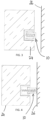
- Figs. 3, 4 and 5 show the first fire seal 10 mounted in the side of a floor panel 24, which faces a vertical wall 26 with a gap 28 therebetween. In the active position shown in Fig. 4 , the first fire seal 10 closes the gap 28.
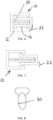
- Figs. 6 and 7 show the first fire seal 10, and with a fusible link 22 extending between the elongate housing 12 and the elongate sealing member 16 so as to in Fig. 6 restrain the elongate sealing member 16 in an inactive position just protruding to a small amount from the elongate housing 12.
- Fig. 7 the fusible link 22 has been broken such that the elongate sealing member 16 extends out of the elongate housing 12, with the external lips on the sealing member engageable 18 with the internal lips 14 on the housing member.
- the fusible link may take a number of different forms, and four examples are shown respectively in Figs. 8 - 11 .
- Figs. 8 and 9 show fusible links 30, 32 made for example of nylon, EPDM, rubber or PVC.
- Figs. 10 and 11 show metal alloy fusible links 34, 36, and include a central part 38 which is intended to fail in the event of a fire.
- the fusible links 22, 30, 32, 34, 36 are intended to fail at temperatures of between 120 - 160°C, and within less than 30 seconds.
- a sealing part may be provided on the outer end of the sealing member 16 to provide a good seal for instance against the wall 26.
- sealing parts Four examples of sealing parts are shown in Figs. 12 to 19 .
- an elongate sealing part 40 is provided which is essentially dome shaped and may be hollow. This may be made of silicone or EPDM.
- Figs. 14 and 15 show a third sealing member 42 with an intumescent sealing part 44 in the form of a strip of intumescent material on the outer end of the sealing member 16.
- Figs. 16 and 17 show a fourth fire seal 46 where the sealing part 48 is in the form of a brush seal.
- Figs. 18 and 19 show a fifth fire seal 50 in which the sealing member is in the form of a vane seal 52 mounted to a distal end of the compression spring 54. As can be seen the vane seal 52 is held in a spiral within the elongate housing 12 until it uncoils when a fusible link 56 has been broken.
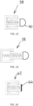
- Figs. 20 and 21 show a sixth fire seal 58.
- no lips are provided on the elongate housing 12 or elongate sealing member 16, and the compression spring 20 retains a link from the housing 12 to the sealing member 16 when in active position.
- Figs. 20 and 21 illustrate another form of fusible link in the form of a sleeve 60 which in this instance is made of PVC, that surrounds the housing 12 and sealing member 16, to retain sealing member 16 in the housing 12 an inactive position, until the sleeve 60 fails for instance in the event of a fire.
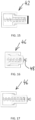
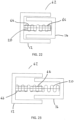
- Figs. 22 to 25 show a seventh fire seal 62 which is similar to the sixth fire seal 58, but includes a plurality of compression springs 20.
- the seventh fire seal 62 includes three compression springs 20 spaced along the length of the fire seal 62, to ensure a uniform transition along the length of the fire seal from an inactive to an active position.
- the compression springs 20 can be fastened to the elongate housing 12 and the elongate sealing member 16 using fixing screws 64 and/or rivets.
- the alignment of the compression springs 20 is maintained by one or more guides 66.
- the one or more guides 66 may be in the form of rods which are locatable inside the helical coil of the compression springs 20 to maintain the alignment of the compression springs 20.
- Figs. 22 and 24 show the seventh fire seal 62 in an inactive position.
- the sealing member 16 is restrained in the elongate housing 12 an inactive position by a sleeve (not shown) extending partially around the elongate housing 12 and elongate sealing member 16 between the elongate housing 12 and the sealing member 16.
- the sleeve may be made from a paper material such that it fails in the event of a fire. Once the sleeve fails, the seventh fire seal 62 transitions to an active position, which is shown in Figs. 23 and 25 .
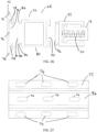
- Fig. 26 shows an eighth fire seal 68, which is similar to the first fire seal 10, but includes an extension arrangement 70.
- the extension arrangement 70 is for spacing the elongate housing 92 and the elongate sealing member 16 from a mounting point such as a floor panel 24 as shown in Fig. 3 & 4 , thereby enabling the elongate housing 92 and the elongate sealing member 16 to be positioned closer to a wall 26. This can be useful where the gap between the floor panel 24 and the wall 26 is too large to seal using only the elongate housing 92 and the sealing member 16.
- the extension arrangement 70 includes a bracket 72, shown in Fig. 27 , for mounting to the floor panel 24.
- the bracket 72 includes one or more holes 74 for receiving fasteners such as screws, to enable the bracket to be secured to the floor panel 24.
- the extension arrangement 70 further includes an elongate spacer 80, which is mountable to the bracket 72.
- the mounting bracket 72 includes a channel 76 which locates a mounting part 82 of the elongate spacer 80.
- the channel 76 of the mounting bracket 72 includes two recesses 78 which locate two corresponding projections 84 on the mounting part 80.
- One or more of the projections 84 may include a tapered portion 86 to enable the respective projection to more readily be inserted into the corresponding recess 78.
- the elongate spacer 80 is locatable between the bracket 72 and the housing 92, and is configured to extend outwardly from the bracket 72 to space the housing 92 from the side of a floor panel 24.
- the elongate spacer 80 includes a cavity 88 extending along the length of the elongate spacer 80, to lower the weight of the elongate spacer 80 and reduce the quantity of materials used.
- the elongate spacer 80 includes a channel 90, which in this example is the same shape as the channel 76 of the mounting bracket 72.
- the channel 90 of the elongate spacer 80 is positioned on an opposite side of the elongate spacer 80 to the mounting part 80.
- the elongate housing 92 of the eighth fire seal 68 is mountable to the elongate spacer 80.
- the elongate housing 92 includes a mounting part 94, which is of the same shape as the mounting part 82 of the elongate spacer 80.
- the mounting part 94 of the elongate housing 92 forms part of the extension arrangement 70, and is locatable in either the channel 76 of the mounting bracket or the channel 90 of the elongate spacer 80.
- Figs. 28A to 28D schematically illustrate the mounting of the elongate spacer 80 to the bracket 72, and the mounting of the elongate housing 92 to the elongate spacer 80.
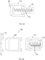
- Fig. 29 illustrates the elongate housing 92, the elongate sealing member 16, and the compression spring 20 of the eighth fire seal 68 in an active position.
- extension arrangement 70 may be provided in the extension arrangement 70, for further spacing the elongate housing 92 from the floor panel 24.
- the extension arrangement 70 could be utilised with any of the fire seals describe herein.
- Figs. 30 to 31 illustrate a ninth fire seal 94, which is similar to the eighth fire seal 68, but includes an intumescent material 96 inside the elongate sealing member 97.
- the intumescent material 96 expands upon heating and retains the ninth fire seal 94 in an active position.
- fire seals which can be active quite quickly, and in many instances significantly more quickly than conventional intumescent seals.
- the fire seals may take a number of different forms as required.
- the fire seal should provide long term maintenance free operation when required, and will not degrade in a similar manner to intumescent materials. Also inconsistences along the fire seal should not be encountered unlike with intumescent materials.
- the fire seal is though of relatively straightforward mechanical construction and can thus be inexpensively produced for long term reliable operation.
- the elongate spacer, the elongate housing and elongate sealing member may be made of steel, aluminium or calcium silicate.
- a resilient arrangement may take a different form, and could for instance include sprung fingers engageable between the elongate housing and elongate sealing member. Different materials could be used than those described.
Landscapes
- Health & Medical Sciences (AREA)
- Public Health (AREA)
- Business, Economics & Management (AREA)
- Emergency Management (AREA)
- Engineering & Computer Science (AREA)
- Mechanical Engineering (AREA)
- Building Environments (AREA)
Claims (9)
- Feuerdichtung, wobei die Feuerdichtung einschließt:ein Gehäuse (12, 92), das mit Lippen (14) versehen ist, wobei das Gehäuse ein längliches Gehäuse in der Form eines Kanalabschnitts ist und sich nach innen erstreckende Lippen (14) an einer offenen Seite aufweist;ein längliches Dichtungselement (16, 38, 42, 97) in der Form eines Kanalabschnitts mit einer zum Gehäuse weisenden Öffnung, wobei das längliche Dichtungselement relativ zum Gehäuse zwischen einer inaktiven Position, die sich mindestens zu einem erheblichen Teil innerhalb des Gehäuses befindet, und einer aktiven Position, die sich zu einem erheblichen Teil vom Gehäuse nach außen erstreckt, verschiebbar beweglich ist, wobei das längliche Dichtungselement (16) mit sich nach außen erstreckenden Lippen (18) auf jeder Seite der Öffnung darin versehen ist und für den Eingriff mit den Lippen (14) des Gehäuses konfiguriert ist, um zu verhindern, dass das längliche Dichtungselement (16) vollständig aus dem Gehäuse (12) herauskommt, wobei der Kanalabschnitt des länglichen Dichtungselements schmaler als der Kanalabschnitt des länglichen Gehäuses ist;ein elastisches Element (20) in der Form mindestens einer Druckfeder (20), das innerhalb des Gehäuses (12) vorgesehen ist und das gegen ein geschlossenes Ende des länglichen Dichtungselements (16) in Eingriff steht, um das längliche Dichtungselement von dem Gehäuse weg zu drängen, wodurch ein Spalt, der an das längliche Gehäuse angrenzt, geschlossen werden kann, indem das längliche Dichtungselement mittels des elastischen Elements in die aktive Position gedrängt wird; undeine Schmelzsicherung (22, 30, 32, 34, 36), die das längliche Dichtungselement (16) in der inaktiven Position hält, wobei die Schmelzsicherung konfiguriert ist, um bei einer erforderlichen erhöhten Temperatur zu versagen, sodass sich das längliche Dichtungselement automatisch in die aktive Position bewegt, zum Beispiel im Falle eines Feuers, wobei die Schmelzsicherung eine Schmelzverbindung (22, 30, 32, 34, 36) ist, die sich in der inaktiven Position zwischen dem Gehäuse und dem länglichen Dichtungselement erstreckt;dadurch gekennzeichnet, dassdie Schmelzverbindung (22, 30, 32, 34, 36) konfiguriert ist, um bei einer erforderlichen erhöhten Temperatur von 120 °C bis 160 °C zu brechen, wobei die Schmelzverbindung (22, 30, 32, 34, 36) in der inaktiven Position und der aktiven Position auf der Außenseite der Vorrichtung positioniert ist.
- Feuerdichtung nach Anspruch 1, wobei die Schmelzverbindung aus Nylon, EPDM, Gummi, PVC oder Metall, insbesondere einer Legierung, hergestellt ist.
- Feuerdichtung nach Anspruch 1, wobei die Schmelzverbindung aus Nylon, EPDM, Gummi oder PVC hergestellt ist.
- Feuerdichtung nach einem der vorstehenden Ansprüche, wobei ein Dichtungsteil (40, 44, 48, 52) auf einer Außenfläche des länglichen Dichtungselements vorgesehen ist und das Dichtungsteil ein beliebiges umfassen kann von: einer Bürste (48), einer Flügeldichtung (52), einer intumeszierenden Dichtung (44), einem länglichen Streifen (40), einem hohlen länglichen Streifen (40) oder einem länglichen Streifen (40), der aus Silikon oder EPDM hergestellt ist.
- Feuerdichtung nach Anspruch 4, wobei das Dichtungsteil ein intumeszierendes Dichtungsteil (44) in der Form eines Streifens aus intumeszierendem Material auf der Außenfläche des länglichen Dichtungselements (16) umfasst.
- Feuerdichtung nach Anspruch 1, wobei eine Führung (66) vorgesehen ist, die innerhalb der spiralförmigen Windung einer der einen oder der mehreren Druckfedern lokalisierbar ist, um die Ausrichtung der Druckfedern aufrechtzuerhalten.
- Feuerdichtung nach einem der vorstehenden Ansprüche, wobei die Feuerdichtung ferner eine Verlängerungsanordnung (70) zum Beabstanden des länglichen Gehäuses und des länglichen Dichtungselements von einem Montagepunkt wie einer Bodenplatte einschließt.
- Feuerdichtung nach Anspruch 7, wobei die Verlängerungsanordnung einen länglichen Abstandshalter (80) für eine Lokalisierung zwischen dem länglichen Gehäuse und einer Halterung einschließt, wobei die Halterung zum Montieren an einer Bodenplatte dient, wobei der Abstandshalter an der Halterung montierbar ist und das Gehäuse an dem Abstandshalter montierbar ist.
- Feuerdichtungsbaugruppe, wobei die Baugruppe eine Feuerdichtung nach einem der vorstehenden Ansprüche einschließt, die an einer Seitenkante einer Bodenplatte (24) vorgesehen ist und zu einer Wand (26) weist, wobei die Feuerdichtung konfiguriert ist, sodass in der inaktiven Position ein Raum (28) zwischen der Bodenplatte und der Wand vorgesehen ist, aber in der aktiven Position das Dichtungselement gegen die Wand in Eingriff steht, um den Raum zu schließen.
Applications Claiming Priority (1)
| Application Number | Priority Date | Filing Date | Title |
|---|---|---|---|
| GBGB1900347.4A GB201900347D0 (en) | 2019-01-10 | 2019-01-10 | Blazeloc |
Publications (2)
| Publication Number | Publication Date |
|---|---|
| EP3679988A1 EP3679988A1 (de) | 2020-07-15 |
| EP3679988B1 true EP3679988B1 (de) | 2023-12-20 |
Family
ID=65528018
Family Applications (1)
| Application Number | Title | Priority Date | Filing Date |
|---|---|---|---|
| EP20150877.7A Active EP3679988B1 (de) | 2019-01-10 | 2020-01-09 | Feuerdichtung |
Country Status (2)
| Country | Link |
|---|---|
| EP (1) | EP3679988B1 (de) |
| GB (2) | GB201900347D0 (de) |
Families Citing this family (1)
| Publication number | Priority date | Publication date | Assignee | Title |
|---|---|---|---|---|
| IT202200018117A1 (it) * | 2022-09-05 | 2024-03-05 | Service Precast Srl | Sistema di protezione tagliafuoco per una cavità di ventilazione |
Family Cites Families (6)
| Publication number | Priority date | Publication date | Assignee | Title |
|---|---|---|---|---|
| DE3239177A1 (de) * | 1982-10-22 | 1984-05-03 | Dictator Technik - Ruef & Co, 8902 Neusäß | Feuerschutztuere |
| JPH0889593A (ja) * | 1994-09-21 | 1996-04-09 | Kawai Musical Instr Mfg Co Ltd | 防火戸 |
| JP2004081459A (ja) * | 2002-08-26 | 2004-03-18 | Yutaka Miyai | 防煙防炎装置 |
| JP5354645B2 (ja) * | 2008-06-25 | 2013-11-27 | 株式会社シブタニ | 両開きドアの召し合わせ部の防火シール装置 |
| KR20100097997A (ko) * | 2009-02-27 | 2010-09-06 | 지만석 | 도어 밀폐 장치 |
| KR101684220B1 (ko) * | 2016-04-07 | 2016-12-07 | 김성배 | 방화문용 틈새 막음 장치 |
-
2019
- 2019-01-10 GB GBGB1900347.4A patent/GB201900347D0/en not_active Ceased
-
2020
- 2020-01-09 EP EP20150877.7A patent/EP3679988B1/de active Active
- 2020-01-09 GB GB2000259.8A patent/GB2582412A/en not_active Withdrawn
Also Published As
| Publication number | Publication date |
|---|---|
| EP3679988A1 (de) | 2020-07-15 |
| GB201900347D0 (en) | 2019-02-27 |
| GB2582412A (en) | 2020-09-23 |
| GB202000259D0 (en) | 2020-02-26 |
Similar Documents
| Publication | Publication Date | Title |
|---|---|---|
| AU2007297871B2 (en) | Thermal pin assembly | |
| JP6157172B2 (ja) | 開口部装置およびこれに用いられるガラス保持金具の取り外し方法 | |
| EP3679988B1 (de) | Feuerdichtung | |
| US8656683B2 (en) | Shutter | |
| EP1687191B1 (de) | Feuerschutzschiebetüranordnung für eine brandschutzwand | |
| KR20050088941A (ko) | 방화셔터의 비상탈출문용 비상자동잠금장치 | |
| US5492208A (en) | Intumescent security pin for fire rated doors | |
| JP6726746B2 (ja) | 鉄道車両の水抜構造 | |
| JP6613046B2 (ja) | 防火建具 | |
| JP6912344B2 (ja) | 建具 | |
| US8316584B2 (en) | Fireproofing element for a door or window leaf | |
| KR200354016Y1 (ko) | 강화유리도어용 프레임의 안전바 이탈방지장치 | |
| EP2878754B1 (de) | Feuerschutztürflügel für eine ein- oder mehrflügel-Feuerschutztür | |
| RS53361B (sr) | Protivpožarna ploča i kompletno staklena vrata za svrhe protivpožarne zaštite | |
| CN215671890U (zh) | 窗装置和包括壁的结构 | |
| DE10248096B3 (de) | Sicherheitstür oder Sicherheitsfenster | |
| JP5902580B2 (ja) | 建具 | |
| EP1682394B1 (de) | Brandschutzwand | |
| CA2988888A1 (en) | Reserve cladding biasing | |
| KR100618537B1 (ko) | 방화셔터용 비상자동잠금장치 | |
| EP2772283A2 (de) | Brandschutzklappe zur Verhinderung von Brand- und Rauchübertragung in einem Rohrgehäuse | |
| WO2017188241A1 (ja) | 防火設備 | |
| AU2010219419B2 (en) | Improvements to Dampers | |
| KR101913583B1 (ko) | 팽창성 발포제를 갖는 방화문 | |
| KR20190089262A (ko) | 단열 안전 도어 |
Legal Events
| Date | Code | Title | Description |
|---|---|---|---|
| PUAI | Public reference made under article 153(3) epc to a published international application that has entered the european phase |
Free format text: ORIGINAL CODE: 0009012 |
|
| STAA | Information on the status of an ep patent application or granted ep patent |
Free format text: STATUS: THE APPLICATION HAS BEEN PUBLISHED |
|
| AK | Designated contracting states |
Kind code of ref document: A1 Designated state(s): AL AT BE BG CH CY CZ DE DK EE ES FI FR GB GR HR HU IE IS IT LI LT LU LV MC MK MT NL NO PL PT RO RS SE SI SK SM TR |
|
| AX | Request for extension of the european patent |
Extension state: BA ME |
|
| STAA | Information on the status of an ep patent application or granted ep patent |
Free format text: STATUS: REQUEST FOR EXAMINATION WAS MADE |
|
| 17P | Request for examination filed |
Effective date: 20210114 |
|
| RBV | Designated contracting states (corrected) |
Designated state(s): AL AT BE BG CH CY CZ DE DK EE ES FI FR GB GR HR HU IE IS IT LI LT LU LV MC MK MT NL NO PL PT RO RS SE SI SK SM TR |
|
| STAA | Information on the status of an ep patent application or granted ep patent |
Free format text: STATUS: EXAMINATION IS IN PROGRESS |
|
| 17Q | First examination report despatched |
Effective date: 20220627 |
|
| GRAP | Despatch of communication of intention to grant a patent |
Free format text: ORIGINAL CODE: EPIDOSNIGR1 |
|
| STAA | Information on the status of an ep patent application or granted ep patent |
Free format text: STATUS: GRANT OF PATENT IS INTENDED |
|
| INTG | Intention to grant announced |
Effective date: 20230718 |
|
| GRAS | Grant fee paid |
Free format text: ORIGINAL CODE: EPIDOSNIGR3 |
|
| GRAA | (expected) grant |
Free format text: ORIGINAL CODE: 0009210 |
|
| STAA | Information on the status of an ep patent application or granted ep patent |
Free format text: STATUS: THE PATENT HAS BEEN GRANTED |
|
| AK | Designated contracting states |
Kind code of ref document: B1 Designated state(s): AL AT BE BG CH CY CZ DE DK EE ES FI FR GB GR HR HU IE IS IT LI LT LU LV MC MK MT NL NO PL PT RO RS SE SI SK SM TR |
|
| REG | Reference to a national code |
Ref country code: GB Ref legal event code: FG4D |
|
| REG | Reference to a national code |
Ref country code: CH Ref legal event code: EP |
|
| REG | Reference to a national code |
Ref country code: DE Ref legal event code: R096 Ref document number: 602020022905 Country of ref document: DE |
|
| REG | Reference to a national code |
Ref country code: IE Ref legal event code: FG4D |
|
| P01 | Opt-out of the competence of the unified patent court (upc) registered |
Effective date: 20240129 |
|
| PG25 | Lapsed in a contracting state [announced via postgrant information from national office to epo] |
Ref country code: GR Free format text: LAPSE BECAUSE OF FAILURE TO SUBMIT A TRANSLATION OF THE DESCRIPTION OR TO PAY THE FEE WITHIN THE PRESCRIBED TIME-LIMIT Effective date: 20240321 |
|
| REG | Reference to a national code |
Ref country code: LT Ref legal event code: MG9D |
|
| PG25 | Lapsed in a contracting state [announced via postgrant information from national office to epo] |
Ref country code: LT Free format text: LAPSE BECAUSE OF FAILURE TO SUBMIT A TRANSLATION OF THE DESCRIPTION OR TO PAY THE FEE WITHIN THE PRESCRIBED TIME-LIMIT Effective date: 20231220 |
|
| REG | Reference to a national code |
Ref country code: NL Ref legal event code: MP Effective date: 20231220 |
|
| PG25 | Lapsed in a contracting state [announced via postgrant information from national office to epo] |
Ref country code: ES Free format text: LAPSE BECAUSE OF FAILURE TO SUBMIT A TRANSLATION OF THE DESCRIPTION OR TO PAY THE FEE WITHIN THE PRESCRIBED TIME-LIMIT Effective date: 20231220 |
|
| PG25 | Lapsed in a contracting state [announced via postgrant information from national office to epo] |
Ref country code: LT Free format text: LAPSE BECAUSE OF FAILURE TO SUBMIT A TRANSLATION OF THE DESCRIPTION OR TO PAY THE FEE WITHIN THE PRESCRIBED TIME-LIMIT Effective date: 20231220 Ref country code: GR Free format text: LAPSE BECAUSE OF FAILURE TO SUBMIT A TRANSLATION OF THE DESCRIPTION OR TO PAY THE FEE WITHIN THE PRESCRIBED TIME-LIMIT Effective date: 20240321 Ref country code: FI Free format text: LAPSE BECAUSE OF FAILURE TO SUBMIT A TRANSLATION OF THE DESCRIPTION OR TO PAY THE FEE WITHIN THE PRESCRIBED TIME-LIMIT Effective date: 20231220 Ref country code: ES Free format text: LAPSE BECAUSE OF FAILURE TO SUBMIT A TRANSLATION OF THE DESCRIPTION OR TO PAY THE FEE WITHIN THE PRESCRIBED TIME-LIMIT Effective date: 20231220 Ref country code: BG Free format text: LAPSE BECAUSE OF FAILURE TO SUBMIT A TRANSLATION OF THE DESCRIPTION OR TO PAY THE FEE WITHIN THE PRESCRIBED TIME-LIMIT Effective date: 20240320 |
|
| REG | Reference to a national code |
Ref country code: AT Ref legal event code: MK05 Ref document number: 1641997 Country of ref document: AT Kind code of ref document: T Effective date: 20231220 |
|
| PG25 | Lapsed in a contracting state [announced via postgrant information from national office to epo] |
Ref country code: NL Free format text: LAPSE BECAUSE OF FAILURE TO SUBMIT A TRANSLATION OF THE DESCRIPTION OR TO PAY THE FEE WITHIN THE PRESCRIBED TIME-LIMIT Effective date: 20231220 |
|
| PG25 | Lapsed in a contracting state [announced via postgrant information from national office to epo] |
Ref country code: SE Free format text: LAPSE BECAUSE OF FAILURE TO SUBMIT A TRANSLATION OF THE DESCRIPTION OR TO PAY THE FEE WITHIN THE PRESCRIBED TIME-LIMIT Effective date: 20231220 Ref country code: RS Free format text: LAPSE BECAUSE OF FAILURE TO SUBMIT A TRANSLATION OF THE DESCRIPTION OR TO PAY THE FEE WITHIN THE PRESCRIBED TIME-LIMIT Effective date: 20231220 Ref country code: NO Free format text: LAPSE BECAUSE OF FAILURE TO SUBMIT A TRANSLATION OF THE DESCRIPTION OR TO PAY THE FEE WITHIN THE PRESCRIBED TIME-LIMIT Effective date: 20240320 Ref country code: NL Free format text: LAPSE BECAUSE OF FAILURE TO SUBMIT A TRANSLATION OF THE DESCRIPTION OR TO PAY THE FEE WITHIN THE PRESCRIBED TIME-LIMIT Effective date: 20231220 Ref country code: LV Free format text: LAPSE BECAUSE OF FAILURE TO SUBMIT A TRANSLATION OF THE DESCRIPTION OR TO PAY THE FEE WITHIN THE PRESCRIBED TIME-LIMIT Effective date: 20231220 Ref country code: HR Free format text: LAPSE BECAUSE OF FAILURE TO SUBMIT A TRANSLATION OF THE DESCRIPTION OR TO PAY THE FEE WITHIN THE PRESCRIBED TIME-LIMIT Effective date: 20231220 |
|
| PG25 | Lapsed in a contracting state [announced via postgrant information from national office to epo] |
Ref country code: IS Free format text: LAPSE BECAUSE OF FAILURE TO SUBMIT A TRANSLATION OF THE DESCRIPTION OR TO PAY THE FEE WITHIN THE PRESCRIBED TIME-LIMIT Effective date: 20240420 |
|
| PG25 | Lapsed in a contracting state [announced via postgrant information from national office to epo] |
Ref country code: AT Free format text: LAPSE BECAUSE OF FAILURE TO SUBMIT A TRANSLATION OF THE DESCRIPTION OR TO PAY THE FEE WITHIN THE PRESCRIBED TIME-LIMIT Effective date: 20231220 Ref country code: CZ Free format text: LAPSE BECAUSE OF FAILURE TO SUBMIT A TRANSLATION OF THE DESCRIPTION OR TO PAY THE FEE WITHIN THE PRESCRIBED TIME-LIMIT Effective date: 20231220 |
|
| PG25 | Lapsed in a contracting state [announced via postgrant information from national office to epo] |
Ref country code: SK Free format text: LAPSE BECAUSE OF FAILURE TO SUBMIT A TRANSLATION OF THE DESCRIPTION OR TO PAY THE FEE WITHIN THE PRESCRIBED TIME-LIMIT Effective date: 20231220 |
|
| PG25 | Lapsed in a contracting state [announced via postgrant information from national office to epo] |
Ref country code: SM Free format text: LAPSE BECAUSE OF FAILURE TO SUBMIT A TRANSLATION OF THE DESCRIPTION OR TO PAY THE FEE WITHIN THE PRESCRIBED TIME-LIMIT Effective date: 20231220 Ref country code: SK Free format text: LAPSE BECAUSE OF FAILURE TO SUBMIT A TRANSLATION OF THE DESCRIPTION OR TO PAY THE FEE WITHIN THE PRESCRIBED TIME-LIMIT Effective date: 20231220 Ref country code: RO Free format text: LAPSE BECAUSE OF FAILURE TO SUBMIT A TRANSLATION OF THE DESCRIPTION OR TO PAY THE FEE WITHIN THE PRESCRIBED TIME-LIMIT Effective date: 20231220 Ref country code: IT Free format text: LAPSE BECAUSE OF FAILURE TO SUBMIT A TRANSLATION OF THE DESCRIPTION OR TO PAY THE FEE WITHIN THE PRESCRIBED TIME-LIMIT Effective date: 20231220 Ref country code: IS Free format text: LAPSE BECAUSE OF FAILURE TO SUBMIT A TRANSLATION OF THE DESCRIPTION OR TO PAY THE FEE WITHIN THE PRESCRIBED TIME-LIMIT Effective date: 20240420 Ref country code: EE Free format text: LAPSE BECAUSE OF FAILURE TO SUBMIT A TRANSLATION OF THE DESCRIPTION OR TO PAY THE FEE WITHIN THE PRESCRIBED TIME-LIMIT Effective date: 20231220 Ref country code: CZ Free format text: LAPSE BECAUSE OF FAILURE TO SUBMIT A TRANSLATION OF THE DESCRIPTION OR TO PAY THE FEE WITHIN THE PRESCRIBED TIME-LIMIT Effective date: 20231220 Ref country code: AT Free format text: LAPSE BECAUSE OF FAILURE TO SUBMIT A TRANSLATION OF THE DESCRIPTION OR TO PAY THE FEE WITHIN THE PRESCRIBED TIME-LIMIT Effective date: 20231220 |
|
| PG25 | Lapsed in a contracting state [announced via postgrant information from national office to epo] |
Ref country code: PL Free format text: LAPSE BECAUSE OF FAILURE TO SUBMIT A TRANSLATION OF THE DESCRIPTION OR TO PAY THE FEE WITHIN THE PRESCRIBED TIME-LIMIT Effective date: 20231220 Ref country code: PT Free format text: LAPSE BECAUSE OF FAILURE TO SUBMIT A TRANSLATION OF THE DESCRIPTION OR TO PAY THE FEE WITHIN THE PRESCRIBED TIME-LIMIT Effective date: 20240422 |
|
| PG25 | Lapsed in a contracting state [announced via postgrant information from national office to epo] |
Ref country code: PT Free format text: LAPSE BECAUSE OF FAILURE TO SUBMIT A TRANSLATION OF THE DESCRIPTION OR TO PAY THE FEE WITHIN THE PRESCRIBED TIME-LIMIT Effective date: 20240422 Ref country code: PL Free format text: LAPSE BECAUSE OF FAILURE TO SUBMIT A TRANSLATION OF THE DESCRIPTION OR TO PAY THE FEE WITHIN THE PRESCRIBED TIME-LIMIT Effective date: 20231220 |
|
| REG | Reference to a national code |
Ref country code: CH Ref legal event code: PL |
|
| PG25 | Lapsed in a contracting state [announced via postgrant information from national office to epo] |
Ref country code: LU Free format text: LAPSE BECAUSE OF NON-PAYMENT OF DUE FEES Effective date: 20240109 |
|
| REG | Reference to a national code |
Ref country code: DE Ref legal event code: R097 Ref document number: 602020022905 Country of ref document: DE |
|
| PG25 | Lapsed in a contracting state [announced via postgrant information from national office to epo] |
Ref country code: LU Free format text: LAPSE BECAUSE OF NON-PAYMENT OF DUE FEES Effective date: 20240109 Ref country code: MC Free format text: LAPSE BECAUSE OF FAILURE TO SUBMIT A TRANSLATION OF THE DESCRIPTION OR TO PAY THE FEE WITHIN THE PRESCRIBED TIME-LIMIT Effective date: 20231220 |
|
| PG25 | Lapsed in a contracting state [announced via postgrant information from national office to epo] |
Ref country code: DK Free format text: LAPSE BECAUSE OF FAILURE TO SUBMIT A TRANSLATION OF THE DESCRIPTION OR TO PAY THE FEE WITHIN THE PRESCRIBED TIME-LIMIT Effective date: 20231220 |
|
| PG25 | Lapsed in a contracting state [announced via postgrant information from national office to epo] |
Ref country code: BE Free format text: LAPSE BECAUSE OF NON-PAYMENT OF DUE FEES Effective date: 20240131 |
|
| PG25 | Lapsed in a contracting state [announced via postgrant information from national office to epo] |
Ref country code: CH Free format text: LAPSE BECAUSE OF NON-PAYMENT OF DUE FEES Effective date: 20240131 |
|
| PLBE | No opposition filed within time limit |
Free format text: ORIGINAL CODE: 0009261 |
|
| STAA | Information on the status of an ep patent application or granted ep patent |
Free format text: STATUS: NO OPPOSITION FILED WITHIN TIME LIMIT |
|
| PG25 | Lapsed in a contracting state [announced via postgrant information from national office to epo] |
Ref country code: SI Free format text: LAPSE BECAUSE OF FAILURE TO SUBMIT A TRANSLATION OF THE DESCRIPTION OR TO PAY THE FEE WITHIN THE PRESCRIBED TIME-LIMIT Effective date: 20231220 |
|
| PG25 | Lapsed in a contracting state [announced via postgrant information from national office to epo] |
Ref country code: SI Free format text: LAPSE BECAUSE OF FAILURE TO SUBMIT A TRANSLATION OF THE DESCRIPTION OR TO PAY THE FEE WITHIN THE PRESCRIBED TIME-LIMIT Effective date: 20231220 Ref country code: DK Free format text: LAPSE BECAUSE OF FAILURE TO SUBMIT A TRANSLATION OF THE DESCRIPTION OR TO PAY THE FEE WITHIN THE PRESCRIBED TIME-LIMIT Effective date: 20231220 Ref country code: CH Free format text: LAPSE BECAUSE OF NON-PAYMENT OF DUE FEES Effective date: 20240131 Ref country code: BE Free format text: LAPSE BECAUSE OF NON-PAYMENT OF DUE FEES Effective date: 20240131 |
|
| REG | Reference to a national code |
Ref country code: BE Ref legal event code: MM Effective date: 20240131 |
|
| 26N | No opposition filed |
Effective date: 20240923 |
|
| PG25 | Lapsed in a contracting state [announced via postgrant information from national office to epo] |
Ref country code: IE Free format text: LAPSE BECAUSE OF NON-PAYMENT OF DUE FEES Effective date: 20240109 |
|
| PG25 | Lapsed in a contracting state [announced via postgrant information from national office to epo] |
Ref country code: IE Free format text: LAPSE BECAUSE OF NON-PAYMENT OF DUE FEES Effective date: 20240109 |
|
| PG25 | Lapsed in a contracting state [announced via postgrant information from national office to epo] |
Ref country code: CY Free format text: LAPSE BECAUSE OF FAILURE TO SUBMIT A TRANSLATION OF THE DESCRIPTION OR TO PAY THE FEE WITHIN THE PRESCRIBED TIME-LIMIT; INVALID AB INITIO Effective date: 20200109 |
|
| PG25 | Lapsed in a contracting state [announced via postgrant information from national office to epo] |
Ref country code: HU Free format text: LAPSE BECAUSE OF FAILURE TO SUBMIT A TRANSLATION OF THE DESCRIPTION OR TO PAY THE FEE WITHIN THE PRESCRIBED TIME-LIMIT; INVALID AB INITIO Effective date: 20200109 |
|
| PG25 | Lapsed in a contracting state [announced via postgrant information from national office to epo] |
Ref country code: TR Free format text: LAPSE BECAUSE OF FAILURE TO SUBMIT A TRANSLATION OF THE DESCRIPTION OR TO PAY THE FEE WITHIN THE PRESCRIBED TIME-LIMIT Effective date: 20231220 |
|
| PGFP | Annual fee paid to national office [announced via postgrant information from national office to epo] |
Ref country code: GB Payment date: 20260123 Year of fee payment: 7 |
|
| PGFP | Annual fee paid to national office [announced via postgrant information from national office to epo] |
Ref country code: DE Payment date: 20260121 Year of fee payment: 7 |
|
| PGFP | Annual fee paid to national office [announced via postgrant information from national office to epo] |
Ref country code: FR Payment date: 20260123 Year of fee payment: 7 |