EP3678937B1 - Véhicule aérien sans pilote équipé de cage extérieure de protection - Google Patents
Véhicule aérien sans pilote équipé de cage extérieure de protection Download PDFInfo
- Publication number
- EP3678937B1 EP3678937B1 EP18765115.3A EP18765115A EP3678937B1 EP 3678937 B1 EP3678937 B1 EP 3678937B1 EP 18765115 A EP18765115 A EP 18765115A EP 3678937 B1 EP3678937 B1 EP 3678937B1
- Authority
- EP
- European Patent Office
- Prior art keywords
- outer frame
- frame
- gimbal
- uav
- propulsion
- Prior art date
- Legal status (The legal status is an assumption and is not a legal conclusion. Google has not performed a legal analysis and makes no representation as to the accuracy of the status listed.)
- Active
Links
- 230000001681 protective effect Effects 0.000 title claims description 32
- 230000008878 coupling Effects 0.000 claims description 68
- 238000010168 coupling process Methods 0.000 claims description 68
- 238000005859 coupling reaction Methods 0.000 claims description 68
- 230000008859 change Effects 0.000 claims description 7
- 230000001154 acute effect Effects 0.000 claims description 3
- 230000002441 reversible effect Effects 0.000 description 8
- 238000004891 communication Methods 0.000 description 7
- 238000007689 inspection Methods 0.000 description 6
- 230000010354 integration Effects 0.000 description 6
- 230000007246 mechanism Effects 0.000 description 6
- 230000006378 damage Effects 0.000 description 5
- 230000006870 function Effects 0.000 description 5
- 230000008901 benefit Effects 0.000 description 4
- 230000009467 reduction Effects 0.000 description 4
- 208000028804 PERCHING syndrome Diseases 0.000 description 3
- 230000005540 biological transmission Effects 0.000 description 3
- 230000033001 locomotion Effects 0.000 description 3
- 239000000523 sample Substances 0.000 description 3
- 238000009987 spinning Methods 0.000 description 3
- RZVHIXYEVGDQDX-UHFFFAOYSA-N 9,10-anthraquinone Chemical compound C1=CC=C2C(=O)C3=CC=CC=C3C(=O)C2=C1 RZVHIXYEVGDQDX-UHFFFAOYSA-N 0.000 description 2
- 230000000295 complement effect Effects 0.000 description 2
- 230000007613 environmental effect Effects 0.000 description 2
- 230000035939 shock Effects 0.000 description 2
- 230000006641 stabilisation Effects 0.000 description 2
- 238000011105 stabilization Methods 0.000 description 2
- 230000003068 static effect Effects 0.000 description 2
- 241000269799 Perca fluviatilis Species 0.000 description 1
- 208000027418 Wounds and injury Diseases 0.000 description 1
- 230000015572 biosynthetic process Effects 0.000 description 1
- 239000004020 conductor Substances 0.000 description 1
- 238000006073 displacement reaction Methods 0.000 description 1
- 230000000694 effects Effects 0.000 description 1
- 230000005489 elastic deformation Effects 0.000 description 1
- 230000010006 flight Effects 0.000 description 1
- 239000012530 fluid Substances 0.000 description 1
- 239000000446 fuel Substances 0.000 description 1
- 208000014674 injury Diseases 0.000 description 1
- 230000003287 optical effect Effects 0.000 description 1
- 210000000056 organ Anatomy 0.000 description 1
- 238000011084 recovery Methods 0.000 description 1
- 230000008439 repair process Effects 0.000 description 1
- 230000001953 sensory effect Effects 0.000 description 1
- 230000000087 stabilizing effect Effects 0.000 description 1
- 239000000126 substance Substances 0.000 description 1
- 239000000725 suspension Substances 0.000 description 1
Images


Classifications
-
- B—PERFORMING OPERATIONS; TRANSPORTING
- B64—AIRCRAFT; AVIATION; COSMONAUTICS
- B64C—AEROPLANES; HELICOPTERS
- B64C39/00—Aircraft not otherwise provided for
- B64C39/02—Aircraft not otherwise provided for characterised by special use
- B64C39/024—Aircraft not otherwise provided for characterised by special use of the remote controlled vehicle type, i.e. RPV
-
- B—PERFORMING OPERATIONS; TRANSPORTING
- B64—AIRCRAFT; AVIATION; COSMONAUTICS
- B64U—UNMANNED AERIAL VEHICLES [UAV]; EQUIPMENT THEREFOR
- B64U50/00—Propulsion; Power supply
- B64U50/10—Propulsion
- B64U50/13—Propulsion using external fans or propellers
-
- B—PERFORMING OPERATIONS; TRANSPORTING
- B60—VEHICLES IN GENERAL
- B60L—PROPULSION OF ELECTRICALLY-PROPELLED VEHICLES; SUPPLYING ELECTRIC POWER FOR AUXILIARY EQUIPMENT OF ELECTRICALLY-PROPELLED VEHICLES; ELECTRODYNAMIC BRAKE SYSTEMS FOR VEHICLES IN GENERAL; MAGNETIC SUSPENSION OR LEVITATION FOR VEHICLES; MONITORING OPERATING VARIABLES OF ELECTRICALLY-PROPELLED VEHICLES; ELECTRIC SAFETY DEVICES FOR ELECTRICALLY-PROPELLED VEHICLES
- B60L50/00—Electric propulsion with power supplied within the vehicle
- B60L50/50—Electric propulsion with power supplied within the vehicle using propulsion power supplied by batteries or fuel cells
- B60L50/60—Electric propulsion with power supplied within the vehicle using propulsion power supplied by batteries or fuel cells using power supplied by batteries
-
- B—PERFORMING OPERATIONS; TRANSPORTING
- B64—AIRCRAFT; AVIATION; COSMONAUTICS
- B64D—EQUIPMENT FOR FITTING IN OR TO AIRCRAFT; FLIGHT SUITS; PARACHUTES; ARRANGEMENTS OR MOUNTING OF POWER PLANTS OR PROPULSION TRANSMISSIONS IN AIRCRAFT
- B64D27/00—Arrangement or mounting of power plant in aircraft; Aircraft characterised thereby
- B64D27/02—Aircraft characterised by the type or position of power plant
- B64D27/24—Aircraft characterised by the type or position of power plant using steam, electricity, or spring force
-
- B—PERFORMING OPERATIONS; TRANSPORTING
- B64—AIRCRAFT; AVIATION; COSMONAUTICS
- B64D—EQUIPMENT FOR FITTING IN OR TO AIRCRAFT; FLIGHT SUITS; PARACHUTES; ARRANGEMENTS OR MOUNTING OF POWER PLANTS OR PROPULSION TRANSMISSIONS IN AIRCRAFT
- B64D47/00—Equipment not otherwise provided for
- B64D47/02—Arrangements or adaptations of signal or lighting devices
-
- B—PERFORMING OPERATIONS; TRANSPORTING
- B64—AIRCRAFT; AVIATION; COSMONAUTICS
- B64D—EQUIPMENT FOR FITTING IN OR TO AIRCRAFT; FLIGHT SUITS; PARACHUTES; ARRANGEMENTS OR MOUNTING OF POWER PLANTS OR PROPULSION TRANSMISSIONS IN AIRCRAFT
- B64D47/00—Equipment not otherwise provided for
- B64D47/08—Arrangements of cameras
-
- B—PERFORMING OPERATIONS; TRANSPORTING
- B64—AIRCRAFT; AVIATION; COSMONAUTICS
- B64U—UNMANNED AERIAL VEHICLES [UAV]; EQUIPMENT THEREFOR
- B64U10/00—Type of UAV
- B64U10/10—Rotorcrafts
- B64U10/13—Flying platforms
- B64U10/14—Flying platforms with four distinct rotor axes, e.g. quadcopters
-
- B—PERFORMING OPERATIONS; TRANSPORTING
- B64—AIRCRAFT; AVIATION; COSMONAUTICS
- B64U—UNMANNED AERIAL VEHICLES [UAV]; EQUIPMENT THEREFOR
- B64U30/00—Means for producing lift; Empennages; Arrangements thereof
- B64U30/20—Rotors; Rotor supports
- B64U30/24—Coaxial rotors
-
- B—PERFORMING OPERATIONS; TRANSPORTING
- B64—AIRCRAFT; AVIATION; COSMONAUTICS
- B64U—UNMANNED AERIAL VEHICLES [UAV]; EQUIPMENT THEREFOR
- B64U30/00—Means for producing lift; Empennages; Arrangements thereof
- B64U30/20—Rotors; Rotor supports
- B64U30/29—Constructional aspects of rotors or rotor supports; Arrangements thereof
- B64U30/296—Rotors with variable spatial positions relative to the UAV body
- B64U30/297—Tilting rotors
-
- B—PERFORMING OPERATIONS; TRANSPORTING
- B64—AIRCRAFT; AVIATION; COSMONAUTICS
- B64U—UNMANNED AERIAL VEHICLES [UAV]; EQUIPMENT THEREFOR
- B64U30/00—Means for producing lift; Empennages; Arrangements thereof
- B64U30/20—Rotors; Rotor supports
- B64U30/29—Constructional aspects of rotors or rotor supports; Arrangements thereof
- B64U30/299—Rotor guards
-
- B—PERFORMING OPERATIONS; TRANSPORTING
- B64—AIRCRAFT; AVIATION; COSMONAUTICS
- B64U—UNMANNED AERIAL VEHICLES [UAV]; EQUIPMENT THEREFOR
- B64U50/00—Propulsion; Power supply
- B64U50/30—Supply or distribution of electrical power
-
- B—PERFORMING OPERATIONS; TRANSPORTING
- B60—VEHICLES IN GENERAL
- B60L—PROPULSION OF ELECTRICALLY-PROPELLED VEHICLES; SUPPLYING ELECTRIC POWER FOR AUXILIARY EQUIPMENT OF ELECTRICALLY-PROPELLED VEHICLES; ELECTRODYNAMIC BRAKE SYSTEMS FOR VEHICLES IN GENERAL; MAGNETIC SUSPENSION OR LEVITATION FOR VEHICLES; MONITORING OPERATING VARIABLES OF ELECTRICALLY-PROPELLED VEHICLES; ELECTRIC SAFETY DEVICES FOR ELECTRICALLY-PROPELLED VEHICLES
- B60L2200/00—Type of vehicles
- B60L2200/10—Air crafts
-
- B—PERFORMING OPERATIONS; TRANSPORTING
- B64—AIRCRAFT; AVIATION; COSMONAUTICS
- B64U—UNMANNED AERIAL VEHICLES [UAV]; EQUIPMENT THEREFOR
- B64U10/00—Type of UAV
- B64U10/10—Rotorcrafts
- B64U10/13—Flying platforms
-
- B—PERFORMING OPERATIONS; TRANSPORTING
- B64—AIRCRAFT; AVIATION; COSMONAUTICS
- B64U—UNMANNED AERIAL VEHICLES [UAV]; EQUIPMENT THEREFOR
- B64U2201/00—UAVs characterised by their flight controls
- B64U2201/20—Remote controls
-
- B—PERFORMING OPERATIONS; TRANSPORTING
- B64—AIRCRAFT; AVIATION; COSMONAUTICS
- B64U—UNMANNED AERIAL VEHICLES [UAV]; EQUIPMENT THEREFOR
- B64U30/00—Means for producing lift; Empennages; Arrangements thereof
- B64U30/20—Rotors; Rotor supports
-
- B—PERFORMING OPERATIONS; TRANSPORTING
- B64—AIRCRAFT; AVIATION; COSMONAUTICS
- B64U—UNMANNED AERIAL VEHICLES [UAV]; EQUIPMENT THEREFOR
- B64U50/00—Propulsion; Power supply
- B64U50/10—Propulsion
- B64U50/19—Propulsion using electrically powered motors
-
- Y—GENERAL TAGGING OF NEW TECHNOLOGICAL DEVELOPMENTS; GENERAL TAGGING OF CROSS-SECTIONAL TECHNOLOGIES SPANNING OVER SEVERAL SECTIONS OF THE IPC; TECHNICAL SUBJECTS COVERED BY FORMER USPC CROSS-REFERENCE ART COLLECTIONS [XRACs] AND DIGESTS
- Y02—TECHNOLOGIES OR APPLICATIONS FOR MITIGATION OR ADAPTATION AGAINST CLIMATE CHANGE
- Y02T—CLIMATE CHANGE MITIGATION TECHNOLOGIES RELATED TO TRANSPORTATION
- Y02T10/00—Road transport of goods or passengers
- Y02T10/60—Other road transportation technologies with climate change mitigation effect
- Y02T10/70—Energy storage systems for electromobility, e.g. batteries
Definitions
- the present invention relates to an unmanned aerial vehicle (hereinafter also referred to as "UAV") with a protective outer cage.
- UAV unmanned aerial vehicle
- the inner frame of an aerial vehicle typically includes a propulsion unit with rotating propellers, a control system to control and steer the aerial vehicle, a battery, possibly other components such as sensors, cameras, or goods to be delivered, some of these typically being sensitive to strong impacts, or requiring ease of access by an operator.
- the inner frame may be comprised of an inner support structure, such as a decoupling mechanism, or any other stiff mechanical apparatus which is not meant to come in contact with external obstacles.
- aerial vehicles are provided with protective outer structures to avoid injury to persons and damage to the environment, as well as to protect the aerial vehicle from damage.
- Examples of aerial vehicle with protective cages are illustrated in US D659771 , WO 2015/135951 , WO2004113166 , WO2015022455 , US9150069 , US20100224723 , US7273195 , US20090075551 , US8147289 , US8528854 , WO2015105554 , and WO2014198774 .
- Conventional protective cages are usually capable of protecting the inner frame of the aerial vehicle (in particular propellers) from touching objects during relatively low-energy contacts, sometimes only from some directions (e.g. on the sides).
- the outer protective cage is coupled to the flight propulsion system via a gimbal system that allows free rotation of the outer cage relative to the flight propulsion system.
- a camera and sensors are mounted on the flight propulsion system within the outer cage. While this known design allows to produce a very light and resistant UAV that is particularly advantageous for inspection applications and other applications in confined spaces, the outer cage somewhat hinders viewing by the camera and sensors mounted on the propulsion unit within the outer cage. It is also difficult to install a robot manipulator or other tool that may for instance be useful for picking and placing objects or collecting samples or perching against a surface.
- US 2016/001875 discloses a prior art example of active orientation of the outer cage via actuators.
- An object of the invention is to provide an unmanned aerial vehicle (UAV) with a protective outer cage that provides a high resistance against collisions and that offers good protection to a flight propulsion system and other components mounted within the cage, yet has good maneuverability and provides good access for functional devices or sensors, for instance image capture system, lighting system, robot manipulator, and other functional or sensory devices installed in the UAV.
- UAV unmanned aerial vehicle
- UAV Ultrasound Vehicle
- Objects of the invention have been achieved by providing an unmanned aerial vehicle (UAV) according to claim 1.
- UAV unmanned aerial vehicle
- the outer frame actuation system comprises an outer air propulsion system fixed to the outer frame or to a frame of the gimbal system.
- the inner flight propulsion system may be configured to enable the UAV to be suspended or flown without thrust from the outer propulsion system, and/or the outer propulsion system may be configured to enable the UAV to be suspended or flown without thrust from the inner flight propulsion system.
- the inner flight propulsion system is configured to enable the UAV to be suspended or flown without thrust from the outer propulsion system.
- the outer air propulsion system comprises one or a plurality of propulsion units comprising propellers or turbines driven by motors controlled by the control system to govern the orientation of the outer frame with respect to the inner frame.
- the outer frame propulsion units may be positioned proximate but offset laterally from a gimbal axis coupled rotationally to the outer frame.
- At least one of the outer frame propulsion units is reversible and controllable to generate forward or reverse thrust.
- the outer frame propulsion units may be tilted so as generate thrust in a direction forming an acute angle with the vertical direction during stable flight, configured to control orientation of the outer frame around a Yaw axis.
- the outer air propulsion system may comprise propulsion units fixed to a frame of the gimbal system, the frame coupled to the outer frame via one of said rotational couplings.
- the outer air propulsion system may comprise at least two propulsion units, at least one propulsion unit mounted proximate each rotational coupling connecting the outer frame to the gimbal frame.
- the outer air propulsion system may be configured to generate lift in conjunction with the inner propulsion system for the flight of the UAV.
- At least one of said rotational couplings connecting the outer frame to a gimbal frame further comprises a clutch configured to block rotation of the outer frame with the gimbal frame and to allow decoupling of the outer frame from the gimbal frame.
- At least one of said rotational couplings further comprises an electrical rotary actuator to actively orient the inner frame relative to the outer frame.
- the inner propulsion system may have a single propulsion unit.
- the inner propulsion system may comprise a plurality of propulsion units.
- the clutch is electronically activated.
- At least one rotational coupling may comprise a torque sensor to sense a collision event.
- the clutch may be passive and configured to slip when a predefined amplitude of torque is exceeded.
- the outer frame may form an outer protective cage that surrounds and protects the inner flight propulsion system.
- the outer frame may form a generally non-spherical ovoid, oblong or elongated shape.
- the outer frame may comprise a support ring forming a port hole configured to provide access for components mounted at the port hole.
- the outer propulsion system may be mounted inside the outer protective cage formed by the outer frame.
- the outer propulsion system may be mounted in a removable manner, for instance by a mechanical connector or clamp mechanism to the outer protective cage, to enable easy dismounting and removal of the outer propulsion system.
- components of the UAV may be mounted at opposite ends of a long axis of the outer frame, said components including any one or more of a surveillance system, a functional system, sensors, lighting, elements of the control system, and elements of the power source.
- a surveillance system comprising any one or more of camera, a, distance sensor, a lighting system, is mounted to the outer frame.
- a functional system comprising any one or more of a robotic gripper or object manipulator, an electromagnet, a sensing probe, a fluid dispenser, a sample collector, is mounted to the outer frame.
- the gimbal system comprises a rotation joint, the inner frame comprising a beam coupled rotationally to the rotation joint forming a first of said forming said two rotational couplings, a second beam coupled rotationally to the rotation joint forming a second of said two rotational couplings, the second beam constituting part of the outer frame or part of the gimbal system.
- the rotation joint comprises first and second axes of rotation that are orthogonal and arranged in respective first and second offset parallel planes.
- the inner frame beam extends uninterrupted through the rotation joint and the second beam extends uninterrupted through the rotation joint.
- the power source comprises a battery
- the outer frame comprise a battery mounting frame with an adjustable battery mounting position on an opposite side of a rotation coupling from a functional system or payload to change the position of the battery along the battery mounting beam and thus adjust the center of mass of the outer frame.
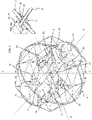
- an unmanned aerial vehicle (UAV) 1 comprises an inner frame 2, an inner propulsion system 4 mounted on the inner frame 2, an outer frame 8, and a gimbal system 6 coupling the inner propulsion system 4 to the outer frame 8.
- the gimbal system 6 comprises at least two rotational couplings, a first rotational coupling 26 coupling a gimbal frame 28 to the inner frame 2, and a second rotational coupling 30 coupling the gimbal frame 28 to the outer frame 8, or to a subsequent gimbal frame that is in turn rotationally coupled to the outer frame 8.
- the gimbal system may comprise additional gimbal frames rotationally coupled between the outer frame and inner frame.
- the UAV 1 further comprises one or more control units 14 to control the flight of the UAV and various functions of the UAV and one or more power sources 12, in the form of one or more batteries.
- the control unit 14 may comprise micro-processors and various electronics circuit components to control motors, variable aerodynamic control elements of the propulsion system, actuators, sensors and functional devices and other components of the UAV.
- the control unit may further comprise wireless communication systems to receive commands transmitted remotely or transmit data to a remote unit wirelessly.
- a surveillance system 16 comprising one or more cameras may be mounted to the UAV, preferably to the outer frame 8.
- the cameras may be used for inspection purposes, taking still and/or moving images that may be stored locally in a memory of the control unit or camera and optionally transmitted wirelessly to a remote unit.
- the UAV 1 may further comprise sensors such as inertial sensors that may be used for directional control of the UAV but also for registering collision and also detecting excessive inertial shocks that may be a sign of damage to components of the UAV. Sensors may further include strain gauges or other force sensing elements positioned on the components of outer protective cage and optionally on elements of the inner frame or gimbal system of the UAV.
- the flight propulsion system may comprise various other configurations and components per se known in the prior art, for instance according to the system described in WO 2014198774 incorporated herein by reference.
- the inner propulsion system 4 may constitute a flight propulsion system for the UAV 1 in whole, or in part, depending on the embodiment, as will best be understood hereinafter.
- the inner propulsion system 4 comprises one or more propulsion units 20 comprising propellers 24 and motors 22 driving the propellers.
- Each propulsion unit 20 may have a single propeller or two or more coaxially mounted propellers.
- Propulsion units may also be in the form of turbines.
- the inner propulsion system may advantageously comprise four motors 22 with propellers 24 in an essentially rectangular formation as is per se known in the art. However, other variants of a propulsion system may be used, for example with one, two, three, five or more propulsion units 20 in various geometric dispositions.
- the propulsion units of the inner propulsion system can be tilted to increase the control authority around the yaw axis.
- the propellers in multi-propulsion unit variants may advantageously be arranged in offset parallel planes, for example a first pair of propellers in a first plane and a second pair of propellers in a second plane such that the blades of the propellers may overlap.
- This allows the surface area covered by the propellers to be compact and optimized for the propulsion force as a function of the surface area covered.
- a pair of propellers 24a that are diagonally arranged with respect to the other pair of propellers 24b are inverted with respect to the other pair such that one pair of propellers 24a are on one side of the inner frame 2 and the other pair of propellers 24b on the other opposite side of the inner frame 2.
- the gimbal frame 28, or gimbal frames if they are a plurality of gimbal frames, may have various shapes, their function being to support and interconnect the inner frame 2 to the outer frame 8 in a lightweight and stable configuration.
- the rotational couplings 26, 30 comprise bearings, for instance roller bearings that minimize rotational friction, however other bearing arrangements may be utilized, for instance of the journal bearing type or even spring couplings that allow a certain degree of rotation of the gimbal frame with respect to the outer and inner frames.
- the rotational coupling may comprise an elastomeric joint or a clock spring joint that allows a certain angle of relative rotation of the two coupled parts around the joint, for instance plus/minus 30 to 360 degrees.
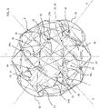
- the outer frame 8 forms an outer protective cage that protects the inner propulsion system 4 and various other components of the UAV mounted within the cage 8.
- the outer frame prevents the blades 24 of the propulsion system 4 from harming persons or from being damaged, and the outer frame further protects the components mounted in the UAV from being damaged upon impact with external objects.
- the outer frame 8 may comprise a plurality of interconnected beams 32 that form a lightweight cage structure that surrounds substantially completely the inner frame 2, inner propulsion system 4, and gimbal system 6 therein.
- the beams may be part of modules that are coupled together in various manners for essentially the same or similar principles as described in WO2014198774 .
- other outer frame structures may be provided, for instance as illustrated in figure 8 .
- the UAV further comprises one or more control systems 14 and one or more power sources 12.
- the power source may in particular be in a form of one or more electrical batteries to supply electrical energy to electrical and electronic components of the UAV and to drive electrical motors of the propulsion system.
- Other forms of energy and motors may however be used without departing from the scope of the invention, for instance fuel as an energy source and thermally driven power systems.
- the power source 12 may include a power source mounted on the inner frame 2 and/or the inner propulsion system 4, and/or a frame of the gimbal system 6, and/or on the outer frame 8.
- a power source mounted on the outer frame may be used to power the various components of the UAV that are fixed to the outer frame. In variants having a single power source, it may be mounted on the inner frame, a frame of the gimbal system, or on the outer frame.
- the mounting position of the battery or batteries, and/or the shape and size of the battery or batteries may be advantageously be selected or configured to counterbalance the weight of other components of the UAV to adjust the center of mass of the UAV as a whole, and/or to adjust the center of mass of the inner frame, and/or of the outer frame, and/or of the gimbal system.
- the position of the battery 12a along a support frame element 27' can be variably adjustable in order to allow the position P of the battery 12a along the support frame element to be adjusted to change the position of the center of mass of the UAV.
- the beam 27 supports a functional system or payload on an opposing side of the rotation coupling joint 29 having a weight that can change according to the use of the UAV.
- the operator can thus adjust the position P of the battery along the support frame element 27' to counter the mass of the functional system 18 or payload at the other end of the beam 27.
- the battery support frame element 27' may be configured to receive batteries of different shapes or sizes.
- the operator can thus adjust the center of mass by selecting the battery among a set of batteries with different masses or different shapes, in order to adjust the center of mass of the UAV.
- the adjustable position or interchangeable battery system discussed in relation to figure 4c may be implemented in other variants, for instance those illustrated in figures 5-7 .
- the shape of the battery 12a may advantageously be longer in the direction of the roll axis A and narrow in a direction orthogonal thereto such that it can be placed between the propellers of the inner propulsion system.
- the latter configuration allows the battery 12a to be as close as possible to the pitch axis B so that its weight can be compensated by the components 14, 16, 18 placed at the front end of the outer frame, further away from the pitch axis B , to take into account the high mass density of the battery.
- Electrical interconnections for the transmission of power and/or control signals and/or data may be provided in the form of rotating electrical joints (e.g. slip rings) in the rotational couplings 26, 30 between the gimbal frame 28, inner frame 2 and outer frame 8.
- rotating electrical joints e.g. slip rings
- Electrical interconnections may also comprise electrical cables mounted along the gimbal frame bridging across the rotational joints 26, 30 with a certain excess length to allow a certain degree of rotation of the joint.
- the flexibility of the electrical conductor and the excess length may allow the joint up to plus and minus 180 degrees of rotation or more.
- electrical connections between the inner and outer frames may be avoided whereby control signals to and from the inner propulsion system 4 may be effected by a wireless communication system such as Wi-Fi, Bluetooth or ZigBee.
- Other wireless communication systems can be employed such as optical communication.
- electrical connections between inner and outer frames can be used for electrical power transmission only, whereas the control signals to and from the inner propulsion system 4 may be transmitted by a wireless communication system.
- the gimbal frame 28 is shaped in a pattern that espouses the revolution of the spinning propellers 24 such that it forms a concave shape facing both longitudinal ends of the oblong outer frame 8 to provide more space for components (e.g. camera, lighting system, laser, clamp, probe, sensors, battery, control system) fixed at the longitudinal ends of the outer frame to the outer frame.
- This design is advantageous because the outer frame propulsion units and payload can be closer to the center of the UAV thanks to the shape of the gimbal frame 28, and the UAV can thus be compact in size.
- the inner frame 2 integrates a battery of the power source 12 and control electronics of the control system 14.
- the battery 12 and control electronics of the control system 14 are integrated only in the outer frame 2, by way of example.
- the gimbal system 6 has only two axes to provide an optimal compromise between performance versus size, weight and complexity of the UAV.
- the control system 14 comprises a control unit comprising a wireless communication system for communicating with an external controller for remote control of the UAV and/or for transmitting data such as data from an image capture device on the UAV or from other sensors measuring various parameters such as flight parameters (e.g. position, speed, orientation, altitude), environmental parameters (e.g. temperature, pressure, chemical identification), integrity of the UAV, and position with respect to external objects.
- flight parameters e.g. position, speed, orientation, altitude
- environmental parameters e.g. temperature, pressure, chemical identification
- integrity of the UAV and position with respect to external objects.
- the control system may comprise a main control unit on the inner frame 2, or on the outer frame 8, and a slave unit on the outer frame respectively inner frame, or they may be two independent control units working together and communicating with the external remote controller.
- the sensors may comprise inertial sensors, navigation and direction sensors, environmental sensors and various other sensors related to the application for which the UAV is intended.
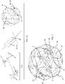
- the UAV may advantageously comprise a surveillance system 16 with an image capture device such as a video camera that may vision through an open longitudinal end 33 of the outer frame 8 such that the camera has an unobstructed viewing angle, yet is protected within the outer cage formed by the outer frame 8.
- an image capture device such as a video camera that may vision through an open longitudinal end 33 of the outer frame 8 such that the camera has an unobstructed viewing angle, yet is protected within the outer cage formed by the outer frame 8.
- One or more functional systems 18 may also be mounted to the outer frame, for instance a robot arm for picking and placing objects, or for reading or taking samples, or for latching or perching the UAV on an external object.
- the functional element may include a prehensile arm to latch the UAV to an external object.
- the prehensile arm may for instance be used to pick up articles, take samples, or to latch the UAV onto an external object.
- the perching function allows the UAV to reduce power on the flight propulsion system, in order to increase autonomy, while allowing inspection to take place in a substantially static position.
- the outer cage may comprise a non-spherical shape, for instance resembling an ovoid shape as illustrated in figures 2-7 whereby components of the UAV other than the inner propulsion system 4 may be mounted on opposite ends of the long axis A .
- Such components may in particular include a surveillance system 16, components of a functional system 18, sensors, and lighting.
- an essentially spherical volume within the cage is needed for free movement of the aforementioned elements.
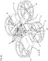
- the outer protective cage may have a generally spherical shape and various components could be fixed for instance in a form of satellites on the outside of the outer frame 8.
- an outer propulsion system 11, power source 12, surveillance system 16 and control system 14 are mounted outside of the outer frame 8.
- the components mounted outside the outer frame 8 may be further surrounded by cage beam elements (not shown) that absorb shocks and protect the outer elements from damage during a collision with an external object.
- the cage beam elements can be mounted flexibly to the outer frame so they can deform upon collision.
- the outer frame 8 comprises an elongate non-spherical shape such that the various components of the UAV may be mounted within the outer cage in a compact, high resistance and light weight configuration.
- the open longitudinal end of the outer frame comprises a support ring 33 forming a port hole defining a passage larger than the spaces between beams of the outer frame to provide good access for the camera viewing angle and for other sensors and lighting components mounted at the port hole.
- the support ring is illustrated in the illustrated embodiments as a circular ring, however the shape of the support ring may be optimized for the viewing position and angle of the surveillance system mounted in the outer frame, whereby the support ring is provided as small as necessary or useful for the viewing angle or access required for cameras and sensors.
- the support ring 33 which forms a closed circuit, also serves as a structural component to couple to beams 32 of the outer frame.
- the surveillance system 16 may comprise more than one camera, for instance cameras at different positions on the outer frame for example pointing in opposite directions such that the environment in front and behind the UAV may be simultaneously or alternatively viewed.
- the UAV further comprises an outer frame actuation system 10 configured to actively orient the outer frame 8 with respect to the inner frame 2 and inner propulsion system 4, while providing a decoupling of the outer frame with respect to the inner frame and inner frame 2 and inner propulsion system 4 in case of collision with an external object or whenever free rotation of the outer frame relative to the inner frame is desired.
- the control system 14 may use orientation sensors on the inner frame, the outer frame, or both, or relative orientation sensors between the inner frame and outer frame (e.g. encoders in the rotation couplings).
- the outer frame actuation system comprises an outer air propulsion system 11 that acts upon the outer frame 8 configured to generate torque in at least one direction to rotate the outer frame around at least one axis.
- An advantage of this embodiment is that the outer air propulsion system does not affect the performance of the decoupling mechanism between outer and inner frames in case of contacts with external objects, because it does not affect the gimbal rotation joints nor rotation freedom of the gimbal mechanism.
- the outer propulsion system comprises one or more propulsion units 34. Each propulsion unit may have a single propeller or two or more coaxially mounted propellers. Propulsion units may also be in the form of turbines.
- Orientation of the outer frame about two or more axes of rotation may be controlled the outer frame actuation system alone, or by a combination of the outer frame actuation system and the inner flight propulsion system, depending on the embodiment, as will be described in more detail hereinbelow.
- the outer frame actuation system 10 allows at least one axis of the outer frame 8 to be held in a stable orientation, or to move into a desired orientation, such that for instance a camera or sensor or functional system fixed to the outer frame may be oriented in a certain direction or kept in a stable orientation with respect to an external object.
- the outer frame actuation system 10 allows two axes, or all three axes of the outer frame 8, to be held in stable orientations, or to move into a desired position, such that for instance a camera or sensor or functional system fixed to the outer frame may be oriented in a certain direction or kept in a stable position with respect to an external object.
- an image capture device such as a camera to point in a certain direction or a certain angle of orientation and to capture the image unhindered by elements or beams of the outer frame (compared to an image capture device fixed to the inner frame) while the UAV is moving.
- a rotation of the outer frame 8 with respect to the inner propulsion system 4 via the gimbal system 6 may occur and can be corrected by the actuation of the outer frame actuation system 10 alone or in conjunction with the inner propulsion system depending on the variant, back to the desired orientation of the outer frame 8.
- the outer frame actuation system 10 may also be used to avoid or to get out of a situation of gimbal lock.
- Figure 15 illustrates schematically orientations of an actuated outer frame 8 relative to the inner frame 2 allowing the outer frame to be stable while the inner frame inclines to navigate or to orient a non-spherical outer frame according to the shape of the environment for instance to go through a hole 3, or to face an object 5, for instance to place a functional system 18 fixed to the outer frame 8 in contact with the object 5.
- a non-actuated decoupled outer frame cannot be used for many applications where components may need to be close to or on the outer frame, because a non-actuated outer frame may be in various uncontrollable orientations while the components on it may need to be oriented in a desired orientation.
- Placing components on the gimbal system or outer frame enables new applications for components working in contact with objects or reduces some limitations present when some components are placed on the inner frame. Actuating the outer frame even allows stabilizing the orientation of these components at a stable orientation, which is usually not possible on the inner frame, which may constantly change orientation due to the control system.
- Typical components that may benefit from being located on the outer frame or gimbal system include:
- the outer air propulsion system 11 comprises one or more propulsion units 34 comprising propellers 38 or turbines driven by motors 36 that may be controlled by the control system 14 to govern the orientation of the outer frame 8 with respect to the inner frame 2 and inner propulsion system 4.
- the inner propulsion system 4 may also be used in conjunction with the outer air propulsion system 11 to control orientation of the outer frame 8.
- the inner propulsion system can be used to generate torque on the outer frame 8 about the yaw axis C since the inner frame 2 is coupled in a torque relationship about the yaw axis C to the outer frame, but is decoupled from the outer frame 8 around the roll axis A and pitch axis B, due to the configuration of the two axis gimbal system 6 in these variants.
- the inner frame is decoupled from the outer frame about all three axes, namely the yaw axis C, roll axis A and pitch axis B.
- control of orientation of the outer frame can also be performed by the outer frame actuation system in conjunction with the inner propulsion system provided that one of more of the rotational couplings of gimbal axes can be blocked using a passive or active clutch as described hereinbelow.
- the orientation of the outer frame may also be solely controlled by the outer air propulsion system.
- the outer air propulsion system comprises a plurality of propulsion units 34, preferably at least 3, more preferably four or more, that are positioned spaced apart and offset from the rotation axes A , B , C such by controlling the thrust generated by each of the propulsion units, torque may be applied on the outer frame around each of the axes A, B, C .
- at least two of the propulsion units may be mounted at a tilt angle with respect to the yaw axis C .
- the outer air propulsion system comprises propulsion units 34 mounted on a frame 28 of the gimbal system rotationally coupled to the inner frame 2 via a first rotational coupling 26 and to the outer frame 8 via a rotational coupling 30.
- the outer air propulsion system comprises at least two propulsion units, at least one proximate each rotational coupling 30 connecting the outer frame 8 to the gimbal frame 28.
- the orientation of the outer frame 8 about at least one gimbal axis B (the pitch axis B in this example) is performed by the propulsion units 34.
- the orientation of the outer frame 8 about the yaw axis C may be performed by the inner propulsion system 4, since the inner frame 2 is coupled in torque to the gimbal beam 28 and outer frame 8 about the yaw axis C.
- orientation of the outer frame 8 about the gimbal axis A may have various configurations.
- the outer frame 8 may rotate about the axis A without any active orientation, either freely rotating about the rotational coupling 30, or restricted from rotation unless there is collision or interference with an external object, whereby the rotational coupling 30 may comprise a limited torque coupling, or an active clutch coupling as described in relation to other embodiments herein.
- yaw axis, pitch axis, and roll axis generally refer to the axes of the main flight propulsion unit of the UAV that counters the weight of the UAV, whereby a change of orientation of the thrust and weight about the yaw, pitch and roll axes changes the direction of flight of the UAV.
- the yaw axis In flight with a static position, without external disturbances, the yaw axis is vertical, however the roll and pitch axes may be interchangeable in the sense that the UAV does not necessarily have a preferred or designated orientation relative to the direction of flight.
- yaw axis, pitch axis, and roll axis in relation to the illustrated embodiments are however not intended to be limiting when referring to a rotational axis of the gimbal system, since for instance the flight propulsion thrust may be a combination of inner and outer propulsion systems such that the orientation of the yaw, roll and pitch axes may not correspond to actual flight axes but rather relative orientation axes of the inner and outer frames.
- the terms yaw axis, pitch axis, or roll axis may thus also be used herein to designate different axes of rotation of the gimbal system and UAV without limitation regarding the orientation with regard to an external reference.
- the outer propulsion system 11 may not only be configured to orient the outer frame 8 with respect to the inner frame but may also be used to participate in providing lift in conjunction with the inner propulsion system 4 for the flight of the UAV 1. In its most common orientation, the UAV will benefit from the outer frame propellers generating forces upward in order to produce more lift which reduces propulsion disk loading, increases flight efficiency and maximizes thrust available for fast maneuvers.
- the distribution of power between the inner propulsion system 4 and outer propulsion system 11 may be configured differently according to various embodiments.
- the outer propulsion system 11 generally provides less lift than the inner propulsion system 4 that provides the main lift for flight of the UAV.
- the outer propulsion system 11 provides the principal lift for flight of the UAV, thus providing more lift than the inner propulsion system 4.
- the outer propulsion system is configured to enable the UAV to be suspended or flown without thrust from the inner flight propulsion system.
- the inner propulsion system may be configured to be sufficiently powerful in order to provide enough lift to suspend the UAV 1 in air in case of failure of the outer propulsion system 11. More importantly, during collisions the outer frame general lift will no longer be vertical and the inner frame propulsion system is configured to provide the general lift while the outer frame is not stabilized.
- the outer propulsion system may comprise one, two, three, four or more propulsion units 34 at various positions fixed to the outer frame 8.
- the inner propulsion system illustrated in figure 8c comprises four propulsion units 20 whereas the inner propulsion system illustrated in figures 8, 8a comprises a single propulsion unit 20.
- the inner propulsion system for instance as illustrated in figures 8, 8a comprise a single propulsion unit 20
- an advantage is that they provide more thrust for the surface area covered by the propeller blades compared to a multi propulsion unit arrangement and thus can be more compact than variants with a plurality of inner propulsion units.
- the orientation of the inner propulsion system may be controlled by providing electrically actuated rotational couplings 26, 30, for instance comprising electrical motors as below in relation to the embodiments illustrated in figures 12 and 13 . This is especially useful for embodiments with a single inner propulsion unit.
- An orientation sensor (not shown) coupled to the inner frame 2, for instance a multi-axis gyroscopic sensor, may be provided to sense the orientation of the inner frame and transmit input to the control system driving the actuated rotation couplings in order to control the orientation of the inner propulsion system according to the desired flight trajectory. This is especially useful for embodiments with a single inner propulsion unit or where the outer propulsion system provides the principle thrust for lift and flight of the UAV.
- an inner propulsion system with a single propulsion unit and electrically actuated rotational couplings of the gimbal system may also be implemented in other variants where the outer frame has a cage configuration and where the inner propulsion system provides most of the lift, for instance replacing the inner propulsion system of the embodiments of figures 1 , 2 , 9 , 10 , and 11 .
- the propellers 38 of the outer propulsion system may be mounted within the outer frame 8 such that they are protected by the outer frame from collision with external objects.
- the propulsion units may be mounted only outside of the outer frame for instance as shown in figure 1 , whereby a protective shroud may be mounted around the propeller or turbine blades.
- the outer propulsion system may be mounted in a removable manner, for instance by a mechanical connector or clamp mechanism to the outer protective cage, to enable easy dismounting and removal of the outer propulsion system for uses where the outer propulsion system is not needed, or for easy replacement of the outer propulsion system.
- the removal of the outer propulsion system may be advantageous in certain circumstances when not required to reduce weight and power consumption, thus also increasing flight autonomy.
- the outer propulsion system may comprise propulsion units that are positioned close to but offset laterally from a gimbal axis A coupled rotationally to the outer frame 8, as shown in figures 2-7 .
- the propulsion units 34 of the outer propulsion system 11 may be mounted on a gimbal frame 28 coupled to the outer frame 8 for instance as illustrated in the embodiments of figures 9 and 10 .
- the outer propulsion system may advantageously comprise propulsion units 11 that are reversible, to provide rapid and versatile orientation of the outer frame 8 around the pitch axis B and roll axis A.
- the ability for the propulsion units 11 to be able to reverse their thrust, aids in maximizing upwards forces in stable orientation, as well as maximize torque and minimize sideways forces during recovery maneuvers (when some propulsion units are reversed).
- one or more propulsion units 11 may advantageously be placed on each side of the horizontal rotation axes A, B .
- the center of mass of the outer frame 8 In order to minimize the power used by the outer frame propulsion units 11 and minimize torque disturbing the outer frame 8 during the UAV's motion, it is advantageous to have the center of mass of the outer frame 8 substantially aligned with both rotation axes A, B (or be below or above both rotation axes) in the stable orientation of the outer frame. If the outer frame may be used in several stable orientations, it is advantageous to have the center of mass of the outer frame substantially aligned with both rotation axes.
- a three-axis gimbal system at least three reversible propulsion units 11 are needed. However, with only three propulsion units, they may have to often switch direction to stabilize a balanced outer frame 8, making a smooth stabilization difficult. It is advantageous to use a fourth propulsion unit to solve the problem without adding too much complexity.
- the four propulsion units can be mounted at different levels and at different angles to improve ease of integration in a compact arrangement and enhance ease of flight control.
- the outer frame propulsion units may be advantageous to place the outer frame propulsion units close to each other along the last decoupling axis A of the gimbal system 6 coupled to the outer frame 8. This works especially well as there is less inertia around this axis and thus requires less torque/spacing between the propulsion units.
- outer frame propulsion units may be placed on different levels to simplify the integration in a compact arrangement.
- a third propulsion unit allows having at least one on each side of each rotation axis and thus stabilizes the outer frame by only generating upward forces.
- the rotational coupling 26, 30 of the gimbal system 6 may have various configurations.
- the inner frame 2 on which the inner propulsion system 4 is mounted is in a form of a beam that extends through a rotation joint 29 forming the rotational couplings 26, 30 of the gimbal system.
- the beam may be an essentially straight beam, although in variants it may also have bends or varying diameters along the length thereof.
- an outer frame beam 27 extends through the rotation joint 29 orthogonally to the inner frame beam.
- the outer frame beam 27 may also be an essentially straight beam, although in variants it may also have bends or varying diameters along the length thereof.
- the outer frame beam 27 is split while the inner frame beam 2 is continuous, whereas in the embodiment of figures 5, 5a , the outer frame beam 27 is continuous while the inner frame beam 2 is split.
- the outer frame beam 27 is connected at opposite outer ends to the outer frame 8 such that the inner frame 2 and inner propulsion system 4 can rotate around the first axis A and around the second axis B within the outer frame 8.
- the gimbal frame coupling joint 29 may have first and second rotational couplings 26, 30 that are in offset planes as illustrated in figures 6 and 6a . This allows the inner frame beam 2 and outer frame beam 27 to both extend through the rotation joint 29 uninterrupted.
- the uninterrupted beams 2, 27 are advantageous not only for structural integrity, but also allow both beams to act as canals for electrical cables, fluidic connections or other functions.
- Various components such as surveillance system 16, functional system 18, power source 12, control unit 14 and outer propulsion system 11 may advantageously be mounted at opposed ends of the outer frame beam 27.
- the electrical rotary actuator actuates the coupling between the gimbal and outer frame such that the rotation of the outer frame 8 relative to the inner frame 2 may be controlled.
- the electrical rotary actuator may alternatively or in addition actuate the coupling between gimbal frame elements, or between the gimbal 6 and inner frame 2.
- the electrical rotary actuator comprises an actuator comprising an electrical motor 44 mounted on one of the frames of the rotational coupling, a rotary output of the actuator coupled to the other frame of the rotational coupling.
- the actuator further comprises a reduction gear assembly coupled to the output of the electrical motor 44, and the electrical motor may for instance be a brushless DC motor that is light weight, typically have a low torque density but a high rotational speed, thus requiring a reduction gear.
- the reduction gear assembly may however render the transmission non-backdrivable.
- the electrical rotary actuator 13 may be provided with a clutch 46 to decouple the frames of the rotational coupling.
- the clutch 46 may either be active, to actively decouple when a collision event is sensed or when commanded by an operator, or may be passive, in particular by allowing a slipping of the clutch when a certain amplitude of torque is exceeded.
- the coupling torque of the passive slip clutch is configured to allow sufficient torque through the coupling for rotation of the outer cage and gimbal elements that are connected together during normal flight operations. In the event of a collision or other event that exceeds the torque threshold for normal operation, the passive clutch is configured to slip.
- the clutch 46 may comprise a pair of magnetic discs 48a, 48b that have complementary magnetically polarised portions N, S that align with each other.
- the rotational coupling may be provided with a torque sensor 51.
- the torque sensor 51 in an embodiment, may comprise a compliant coupling element 52 connected to one plate of the active clutch and to the rotational organ on which that plate is mounted, and sensor 50 to detect a relative displacement of the frame elements due to torque exerted on the compliant element
- the sensor may for instance comprise an encoder disc 50a and encoder 50b connected to complementary parts of the rotational coupling.
- the sensor may comprise a strain gauge to detect an elastic deformation of the compliant element.
- the clutch Upon exceeding a predetermined torque threshold, for instance in a range of between 1/4 and 1/2 of the maximum torque that can be generated by the inner frame propulsion system, the clutch is electronically activated to unlock the rotational coupling and allow movement of the frame elements relative to each other.
- An active or passive clutch can also be used in embodiments comprising outer air propulsion units without a motor or actuator on the rotational coupling. It allows locking the outer frame to the inner frame for standard flights, but to unlock during collision or on command (for an active clutch).
Claims (15)
- Véhicule aérien sans pilote (UAV) (1) comprenant un bâti interne (2), un système de propulsion de vol interne (4) monté sur le bâti interne (2), un bâti externe (8) formant une cage de protection externe qui entoure et protège le système de propulsion de vol interne, un système de cardan (6) comprend une structure de cardan (28) et au moins deux couplages rotatifs (26, 30) avec des axes orthogonaux couplant le système de propulsion interne au bâti externe, un système de commande (14), une source d'alimentation (12) et un système d'actionnement de bâti externe (10) configuré pour orienter activement le bâti externe autour d'au moins un axe par rapport au bâti interne, dans lequel le système d'actionnement de bâti externe comprend un système de propulsion d'air externe (11) configuré pour diriger l'orientation du bâti externe, ledit système de propulsion d'air externe (11) fixé sur le bâti externe ou sur la structure de cardan (28), le système de propulsion de vol interne étant configuré pour permettre à l'UAV d'être en suspension ou de voler sans la poussée du système de propulsion externe.
- UAV selon l'une quelconque des revendications précédentes, dans lequel le système de propulsion d'air externe (11) comprend une pluralité d'unités de propulsion (34) comprenant des propulseurs (38) ou des turbines entraînés par des moteurs (36) commandés par le système de commande (14) pour diriger l'orientation du bâti externe par rapport au bâti interne.
- UAV selon la revendication précédente, dans lequel les unités de propulsion sont positionnées à proximité mais décalées latéralement d'un axe de cardan (A) couplé en rotation au bâti externe.
- UAV selon la revendication 2 ou 3, dans lequel les unités de propulsion de bâti externe sont inclinées afin de générer la poussée dans une direction formant un angle aigu avec la direction verticale pendant un vol stable, configuré pour contrôler l'orientation du bâti externe autour d'un axe de lacet.
- UAV selon l'une quelconque des revendications précédentes, dans lequel le système de propulsion d'air externe comprend des unités de propulsion (34) fixées sur un bâti (28) de la structure de cardan, le bâti (28) étant couplé au bâti externe via l'un desdits couplages de rotation (30).
- UAV selon la revendication précédente, dans lequel le système de propulsion d'air externe comprend au moins deux unités de propulsion, au moins une unité de propulsion montée à proximité de chaque couplage rotatif (30) raccordant le bâti externe à la structure de cardan (28).
- UAV selon l'une quelconque des revendications précédentes, dans lequel le système de propulsion d'air externe est configuré pour générer une levée conjointement avec le système de propulsion interne pour le vol de l'UAV.
- UAV selon l'une quelconque des revendications précédentes, dans lequel au moins l'un desdits couplages rotatifs (30) raccordant le bâti externe à une structure de cardan (28) comprend en outre un embrayage (46) configuré pour empêcher la rotation du bâti externe avec la structure de cardan et pour permettre le découplage du bâti externe de la structure de cardan.
- UAV selon l'une quelconque des revendications précédentes, dans lequel au moins l'un desdits couplages rotatifs comprend en outre un actionneur rotatif électrique pour orienter activement le bâti interne par rapport au bâti externe.
- UAV selon l'une quelconque des revendications précédentes, dans lequel au moins un couplage rotatif comprend un capteur de couple pour détecter un événement de collision.
- UAV selon l'une quelconque des revendications précédentes, dans lequel le système de propulsion externe est monté à l'intérieur de la cage de protection externe formée par le bâti externe.
- UAV selon l'une quelconque des revendications précédentes, dans lequel les composants de l'UAV sont montés au niveau des extrémités opposées d'un axe long A, lesdits composants comprenant l'un quelconque ou plusieurs éléments parmi un système de surveillance (16), un système fonctionnel (18), des capteurs, un éclairage, des éléments du système de commande, des éléments de source d'alimentation (12).
- UAV selon l'une quelconque des revendications précédentes, comprenant en outre un système de surveillance (16) comprenant l'un quelconque ou plusieurs éléments parmi une caméra, un capteur de distance, un système d'éclairage, qui est monté sur le bâti externe.
- UAV selon l'une quelconque des revendications précédentes, dans lequel le système de cardan comprend une articulation de rotation (29), le bâti interne (2) comprenant une poutre couplée en rotation à l'articulation de rotation formant un premier (26) desdits deux couplages rotatifs, une seconde poutre (27) couplée en rotation à l'articulation de rotation formant un second (30) desdits deux couplages de rotation, la seconde poutre faisant partie du bâti externe ou faisant partie du système de cardan.
- UAV selon l'une quelconque des revendications précédentes, dans lequel la source d'alimentation comprend une batterie et le bâti externe comprend un bâti de montage de batterie avec une position de montage de batterie adéquate sur un côté opposé d'un couplage de rotation à partir d'un système fonctionnel ou charge utile pour modifier la position de la batterie le long de la poutre de montage de batterie et ainsi ajuster le centre de masse du bâti externe.
Applications Claiming Priority (2)
| Application Number | Priority Date | Filing Date | Title |
|---|---|---|---|
| EP17189515.4A EP3450310A1 (fr) | 2017-09-05 | 2017-09-05 | Véhicule aérien sans pilote équipé de cage extérieure de protection |
| PCT/EP2018/073783 WO2019048439A1 (fr) | 2017-09-05 | 2018-09-04 | Véhicule aérien sans pilote doté d'une cage externe de protection |
Publications (2)
| Publication Number | Publication Date |
|---|---|
| EP3678937A1 EP3678937A1 (fr) | 2020-07-15 |
| EP3678937B1 true EP3678937B1 (fr) | 2022-10-05 |
Family
ID=59811099
Family Applications (2)
| Application Number | Title | Priority Date | Filing Date |
|---|---|---|---|
| EP17189515.4A Withdrawn EP3450310A1 (fr) | 2017-09-05 | 2017-09-05 | Véhicule aérien sans pilote équipé de cage extérieure de protection |
| EP18765115.3A Active EP3678937B1 (fr) | 2017-09-05 | 2018-09-04 | Véhicule aérien sans pilote équipé de cage extérieure de protection |
Family Applications Before (1)
| Application Number | Title | Priority Date | Filing Date |
|---|---|---|---|
| EP17189515.4A Withdrawn EP3450310A1 (fr) | 2017-09-05 | 2017-09-05 | Véhicule aérien sans pilote équipé de cage extérieure de protection |
Country Status (3)
| Country | Link |
|---|---|
| US (1) | US11708160B2 (fr) |
| EP (2) | EP3450310A1 (fr) |
| WO (1) | WO2019048439A1 (fr) |
Families Citing this family (22)
| Publication number | Priority date | Publication date | Assignee | Title |
|---|---|---|---|---|
| US10112694B2 (en) | 2010-07-23 | 2018-10-30 | Gaofei Yan | Self-righting aeronautical vehicle and method of use |
| US11975864B2 (en) * | 2016-05-17 | 2024-05-07 | Espheric, Llc | Multi sensor support structure |
| KR102624054B1 (ko) * | 2016-12-20 | 2024-01-12 | 삼성전자주식회사 | 무인 비행 장치 |
| EP3450310A1 (fr) * | 2017-09-05 | 2019-03-06 | Flyability SA | Véhicule aérien sans pilote équipé de cage extérieure de protection |
| JP7238380B2 (ja) * | 2018-02-05 | 2023-03-14 | 株式会社リコー | 飛行装置、飛行システム、及び構造物の点検システム |
| US10988241B2 (en) * | 2018-04-20 | 2021-04-27 | Skypersonic, Llc | Removable cage for drone |
| GB201810554D0 (en) * | 2018-06-27 | 2018-08-15 | Macdonald Andrew Norman | Autonomous aerial vehicle with compactible fender cage rotatable about at least two perpendicular axes |
| KR102229169B1 (ko) * | 2019-07-22 | 2021-03-18 | 주식회사 아스트로엑스 | 무인비행체 보호용 이중 안전구조체 |
| LT2019074A (lt) * | 2019-09-18 | 2021-03-25 | Uab "Sg Consulting Baltics & By" | Daugiasraigtis orlaivis |
| JP6790206B1 (ja) * | 2019-09-20 | 2020-11-25 | エスゼット ディージェイアイ テクノロジー カンパニー リミテッドSz Dji Technology Co.,Ltd | 制御装置、制御方法、プログラム、及び記録媒体 |
| CN111003191A (zh) * | 2019-12-03 | 2020-04-14 | 西安航空学院 | 一种无人机防碰撞保护笼及其设计方法 |
| JP6803960B1 (ja) * | 2019-12-09 | 2020-12-23 | エスゼット ディージェイアイ テクノロジー カンパニー リミテッドSz Dji Technology Co.,Ltd | 画像処理装置、画像処理方法、プログラム、及び記録媒体 |
| KR102276791B1 (ko) * | 2020-01-17 | 2021-07-12 | 전주대학교 산학협력단 | 짐벌드론 |
| US20230175247A1 (en) * | 2020-03-16 | 2023-06-08 | Nippon Telegraph And Telephone Corporation | Inspection device, inspection method, and program |
| US11332297B2 (en) * | 2020-04-29 | 2022-05-17 | Amrita Vishwa Vidyapeetham | Protective packaging and delivery |
| FR3116806B1 (fr) * | 2020-11-27 | 2022-11-11 | Airbus Operations Sas | Drone volant pour l’inspection de surfaces et procédé d’inspection de surfaces au moyen d’un tel drone volant |
| US20240002074A1 (en) * | 2020-11-30 | 2024-01-04 | Arizona Board Of Regents On Behalf Of The University Of Arizona | Hybrid exploration and inspection robot |
| IL279694B2 (en) * | 2020-12-22 | 2024-01-01 | Eliahu Guy Itay | Cargo stabilization systems and methods |
| EP4095035A1 (fr) * | 2021-05-25 | 2022-11-30 | Valmet Technologies Oy | Aéronef sans pilote |
| CN113715036A (zh) * | 2021-08-27 | 2021-11-30 | 山东雷纳新材料工程有限公司 | 一种用于电缆隧道的球形机器人 |
| IT202100028253A1 (it) * | 2021-11-05 | 2023-05-05 | Flyability Sa | Aeromobile senza equipaggio (UAV) |
| EP4279380A1 (fr) * | 2022-05-18 | 2023-11-22 | Flyability SA | Uav adav avec capteur lidar 3d |
Citations (1)
| Publication number | Priority date | Publication date | Assignee | Title |
|---|---|---|---|---|
| WO2017184095A1 (fr) * | 2016-04-22 | 2017-10-26 | Gozluklu Burak | Aéronef modulaire et évolutif tridimensionnel |
Family Cites Families (74)
| Publication number | Priority date | Publication date | Assignee | Title |
|---|---|---|---|---|
| US3141479A (en) * | 1961-07-27 | 1964-07-21 | Cons Porcelain Enamel Co | Fluxing pipe and method of making the same or the like |
| US3350035A (en) * | 1964-08-19 | 1967-10-31 | Ernest W Schlieben | Vtol with cylindrical wing |
| US3378037A (en) * | 1965-09-16 | 1968-04-16 | Ceramic Coating Company | Fluxing pipe |
| US3371794A (en) * | 1966-11-28 | 1968-03-05 | Dorr Oliver Inc | Manifolded hydrocyclone unit |
| US3422856A (en) * | 1967-04-11 | 1969-01-21 | John J Hunter | Plastic-lined pipe and method of producing |
| US3568723A (en) * | 1967-06-23 | 1971-03-09 | Du Pont | Metal-ceramic composite structures |
| US3558081A (en) * | 1969-02-20 | 1971-01-26 | Airmarine Corp | Airborne vehicles |
| US3633849A (en) * | 1969-02-25 | 1972-01-11 | Alberto Kling | Flying craft |
| BE792348A (fr) * | 1971-12-28 | 1973-03-30 | Uss Eng & Consult | Procede de liaison de garnitures dans des tubes metalliques |
| US4505346A (en) * | 1982-03-29 | 1985-03-19 | Leonard E. Mueller | Rolling vehicle |
| DE3430067C1 (de) * | 1984-08-16 | 1989-04-06 | Löhr & Bromkamp GmbH, 6050 Offenbach | Gelenkwelle |
| US6349542B1 (en) * | 1998-08-17 | 2002-02-26 | Soundwich, Inc. | Silicon carbide (SiC) composite exhaust manifold and method of making it |
| US6402088B1 (en) * | 2000-08-11 | 2002-06-11 | Aero Copter, Inc. | Passenger vehicle employing a circumferentially disposed rotatable thrust assembly |
| US6725656B2 (en) * | 2001-12-07 | 2004-04-27 | Dan T. Moore Company | Insulated exhaust manifold |
| US6976899B1 (en) * | 2002-01-25 | 2005-12-20 | Kypros Tamanas | All terrain vehicle |
| US7476224B2 (en) * | 2003-03-17 | 2009-01-13 | Petrakis Dennis N | Temperature responsive systems |
| US7959914B2 (en) * | 2003-05-16 | 2011-06-14 | Acorda Therapeutics, Inc. | Methods of reducing extravasation of inflammatory cells |
| FR2856378B1 (fr) | 2003-06-18 | 2006-03-17 | Gaudeffroy Charles Mic Guilhot | Gyroptere a securite renforcee |
| JP4669318B2 (ja) * | 2005-05-11 | 2011-04-13 | カヤバ工業株式会社 | シリンダバレル |
| US7273195B1 (en) | 2005-09-15 | 2007-09-25 | Golliher Clayton R | Vertical lift craft |
| US8109802B2 (en) | 2007-09-15 | 2012-02-07 | Mattel, Inc. | Toy helicopter having a stabilizing bumper |
| US7905447B2 (en) * | 2007-11-16 | 2011-03-15 | Lockheed Martin Corporation | System, method and apparatus for aircraft having counter-rotating, ring-winged rotors |
| US20100224723A1 (en) | 2009-03-03 | 2010-09-09 | Jacob Apkarian | Aerial vehicle |
| US8147289B1 (en) | 2009-03-20 | 2012-04-03 | Lee Jason C | Toy helicopter having guards for preventing contact of the vertical lift rotors |
| US8464978B2 (en) * | 2009-04-16 | 2013-06-18 | The Trustees Of The University Of Pennsylvania | Counter-rotational inertial control of rotorcraft |
| USD648809S1 (en) | 2010-01-04 | 2011-11-15 | Parrot | Flying toy |
| CN101940845A (zh) | 2010-07-23 | 2011-01-12 | 燕高飞 | 蛋壳型外框架 |
| US9067667B2 (en) * | 2010-07-23 | 2015-06-30 | Gaofei Yan | Self-righting frame and aeronautical vehicle |
| US9725158B2 (en) * | 2010-07-23 | 2017-08-08 | Gaofei Yan | Self-righting frame and aeronautical vehicle and method of use |
| WO2012063220A2 (fr) * | 2010-11-12 | 2012-05-18 | Sky Sapience | Unité aérienne et procédé pour l'élévation de charges |
| DE102011010385A1 (de) * | 2011-02-05 | 2012-08-09 | Eads Deutschland Gmbh | Doppelwandiges Rohr und Herstellungsverfahren |
| US9623912B2 (en) * | 2012-09-20 | 2017-04-18 | Polaris Industries Inc. | Utility vehicle |
| US8833189B2 (en) * | 2012-10-02 | 2014-09-16 | Richard Alan Fahnline | Gyroscope device |
| EP2730888A1 (fr) * | 2012-11-07 | 2014-05-14 | Ecole Polytechnique Federale de Lausanne EPFL-SRI | Procédé pour déterminer une direction et amplitude d'une estimation de vitesse de courant d'un dispositif mobile |
| US9061558B2 (en) * | 2012-11-14 | 2015-06-23 | Illinois Institute Of Technology | Hybrid aerial and terrestrial vehicle |
| CN105473442B (zh) * | 2013-06-09 | 2018-04-06 | 瑞士苏黎世联邦理工学院 | 遭遇影响效应器的故障的多旋翼器的受控飞行 |
| US9725170B2 (en) * | 2013-06-11 | 2017-08-08 | Ecole Polytechnique Federale De Lausanne (Epfl) | Vertical take-off and landing aerial vehicle |
| EP2813428B1 (fr) | 2013-06-11 | 2017-04-19 | Ecole Polytechnique Fédérale de Lausanne (EPFL) | Véhicule aérien à décollage et atterrissage verticaux |
| US9611032B2 (en) * | 2014-06-11 | 2017-04-04 | Ecole Polytechnique Federale De Lausanne (Epfl) | Vertical take-off and landing aerial vehicle |
| FR3009711A1 (fr) | 2013-08-14 | 2015-02-20 | Workfly | Enveloppe de securite pour aeronef a voilure tournantes contrarotatives axiales |
| WO2015105554A1 (fr) | 2013-10-15 | 2015-07-16 | Skypersonic Llc | Appareil de type drone fermé et son procédé d'utilisation |
| US10384765B2 (en) * | 2014-02-06 | 2019-08-20 | Bell Helicopter Textron Inc. | Interconnect drive system |
| AT515456B1 (de) * | 2014-02-18 | 2018-04-15 | Iat 21 Innovative Aeronautics Tech Gmbh | Fluggerät |
| WO2015135951A1 (fr) | 2014-03-12 | 2015-09-17 | G.A.M. Progetti Di Guzzardi Andrea E Guffanti Marco Snc | Drone à voilure tournante présentant une structure à protection intrinsèque favorisant la prévention des accidents |
| US20160023755A1 (en) * | 2014-05-05 | 2016-01-28 | King Fahd University Of Petroleum And Minerals | System and method for control of quadrotor air vehicles with tiltable rotors |
| US10099783B1 (en) * | 2014-08-11 | 2018-10-16 | Fpv Manuals Llc | Accessory mounting for rotary wing aircraft |
| US10577098B2 (en) * | 2014-08-22 | 2020-03-03 | Korea Aerospace Research Institute | Drone having reconfigurable shape |
| US9446845B2 (en) * | 2014-10-30 | 2016-09-20 | Ecole Polytechnique Federale De Lausanne (Epfl) | Foldable and self-deployable aerial vehicle |
| US9889930B2 (en) * | 2014-11-24 | 2018-02-13 | Amazon Technologies, Inc. | Unmanned aerial vehicle protective frame configuration |
| US9868524B2 (en) * | 2014-11-11 | 2018-01-16 | Amazon Technologies, Inc. | Unmanned aerial vehicle configuration for extended flight |
| US9760087B2 (en) * | 2015-01-16 | 2017-09-12 | International Business Machines Corporation | Distributed, unmanned aerial vehicle package transport network |
| US11260971B2 (en) * | 2015-02-23 | 2022-03-01 | Aaron Weller | Enclosed unmanned aerial vehicle |
| US10640204B2 (en) * | 2015-03-03 | 2020-05-05 | Amazon Technologies, Inc. | Unmanned aerial vehicle with a tri-wing configuration |
| US9946267B2 (en) * | 2015-04-06 | 2018-04-17 | Thomas A. Youmans | Control and stabilization of a flight vehicle from a detected perturbation by tilt and rotation |
| CN205989812U (zh) * | 2015-06-25 | 2017-03-01 | 瑞德利斯技术公司 | 多旋翼无人机 |
| JP2017035996A (ja) * | 2015-08-11 | 2017-02-16 | 国立大学法人東北大学 | 移動体 |
| JP6597040B2 (ja) * | 2015-08-17 | 2019-10-30 | 富士通株式会社 | 飛翔機のフレーム構造体、飛翔機、飛翔機の使用方法 |
| US10435147B2 (en) * | 2015-11-30 | 2019-10-08 | Cloud Cap Technology, Inc. | Multirotor aircraft control systems |
| JP6738611B2 (ja) * | 2016-02-02 | 2020-08-12 | 株式会社プロドローン | 無人回転翼機 |
| US11158029B2 (en) * | 2016-02-12 | 2021-10-26 | Vigilance Health Imaging Network Inc. | Distortion correction of multiple MRI images based on a full body reference image |
| US20170247107A1 (en) * | 2016-02-29 | 2017-08-31 | GeoScout, Inc. | Rotary-wing vehicle and system |
| US10252795B2 (en) * | 2016-04-08 | 2019-04-09 | Ecole Polytechnique Federale De Lausanne (Epfl) | Foldable aircraft with protective cage for transportation and transportability |
| WO2017184327A1 (fr) * | 2016-04-17 | 2017-10-26 | Volpi Lucio | Véhicule robotisé aérien sans pilote avec mécanisme de montage |
| US10870487B2 (en) * | 2016-07-01 | 2020-12-22 | Bell Textron Inc. | Logistics support aircraft having a minimal drag configuration |
| US10165256B2 (en) * | 2016-09-14 | 2018-12-25 | Amazon Technologies, Inc. | Aerial vehicle optical sensor configuration |
| DE102016117611B4 (de) * | 2016-09-19 | 2020-03-05 | Airrobot Gmbh & Co. Kg | Vorrichtung zum Lufttransport eines Gegenstands |
| CA2983861A1 (fr) * | 2016-11-01 | 2018-05-01 | Robert Jacksy | Systemes de sauvetage controles a distance, et methodes et trousses associees |
| KR102624054B1 (ko) * | 2016-12-20 | 2024-01-12 | 삼성전자주식회사 | 무인 비행 장치 |
| US11591084B2 (en) * | 2017-01-03 | 2023-02-28 | The Texas A&M University System | Cycloidal rotor micro-air vehicle |
| EP3450310A1 (fr) * | 2017-09-05 | 2019-03-06 | Flyability SA | Véhicule aérien sans pilote équipé de cage extérieure de protection |
| CN112236361A (zh) * | 2018-04-10 | 2021-01-15 | 自动化控制系统研究所株式会社 | 无人航空器、无人航空器的飞行控制机构及使用它们的方法 |
| US10988241B2 (en) * | 2018-04-20 | 2021-04-27 | Skypersonic, Llc | Removable cage for drone |
| EP3699083A1 (fr) * | 2019-02-20 | 2020-08-26 | Flyability SA | Véhicule aérien sans pilote dotée d'une propulsion tolérante aux collisions et d'un organe de commande |
| USD890267S1 (en) * | 2019-05-17 | 2020-07-14 | DongGuan Tesmai Electronic Technology Co., LTD | Boomerang |
-
2017
- 2017-09-05 EP EP17189515.4A patent/EP3450310A1/fr not_active Withdrawn
-
2018
- 2018-09-04 WO PCT/EP2018/073783 patent/WO2019048439A1/fr unknown
- 2018-09-04 EP EP18765115.3A patent/EP3678937B1/fr active Active
- 2018-09-04 US US16/643,848 patent/US11708160B2/en active Active
Patent Citations (1)
| Publication number | Priority date | Publication date | Assignee | Title |
|---|---|---|---|---|
| WO2017184095A1 (fr) * | 2016-04-22 | 2017-10-26 | Gozluklu Burak | Aéronef modulaire et évolutif tridimensionnel |
Also Published As
| Publication number | Publication date |
|---|---|
| US20210061463A1 (en) | 2021-03-04 |
| US11708160B2 (en) | 2023-07-25 |
| EP3678937A1 (fr) | 2020-07-15 |
| WO2019048439A1 (fr) | 2019-03-14 |
| EP3450310A1 (fr) | 2019-03-06 |
Similar Documents
| Publication | Publication Date | Title |
|---|---|---|
| EP3678937B1 (fr) | Véhicule aérien sans pilote équipé de cage extérieure de protection | |
| JP7374517B2 (ja) | 衝突耐性のある推進力およびコントローラを備えた無人航空機 | |
| JP6425466B2 (ja) | 飛行装置 | |
| JP5392891B2 (ja) | 飛翔ロボット | |
| US11820475B2 (en) | Linear and angular position stabilization and control of an underwater robotic system | |
| EP3400171B1 (fr) | Aéronef à rotors multiples | |
| EP2813428A1 (fr) | Véhicule aérien à décollage et atterrissage verticaux | |
| US20090250549A1 (en) | Aircraft | |
| JP6536043B2 (ja) | 飛行体 | |
| AU2016319276B2 (en) | Vertical take-off and landing aerial vehicle | |
| WO2016163482A1 (fr) | Unité mobile | |
| JP2023532328A (ja) | 多自由度飛行モードを有するドローンの制御方法 | |
| EP3795470B1 (fr) | Vehicule aerien et methode de controle du vehicule aerien | |
| JP2016135659A (ja) | 飛行体 | |
| EP3772460B1 (fr) | Procédé de commande d'une pluralité d'aéronefs pouvant effectuer des vols stationnaires et système de transport de cargaison aérienne | |
| CN108698692B (zh) | 无机翼的飞行仪器 | |
| CN111055996A (zh) | 飞行装置 | |
| US20240002074A1 (en) | Hybrid exploration and inspection robot | |
| EP3494048B1 (fr) | Véhicule sans pilote | |
| Watanabe et al. | Development of a camera-mounted tethered Quadrotor for inspecting infrastructures | |
| EP4269239A1 (fr) | Véhicule omnidirectionnel à joints rotoïdes passifs | |
| JP6922370B2 (ja) | 飛行体 | |
| KR102035203B1 (ko) | 드론 기술을 이용한 이동 로봇 | |
| Kang et al. | Development of a hovering robot system for calamity observation | |
| Morimoto et al. | Study on navigation system to arbitrary direction for autonomous aerial robot with quad-rotor |
Legal Events
| Date | Code | Title | Description |
|---|---|---|---|
| STAA | Information on the status of an ep patent application or granted ep patent |
Free format text: STATUS: UNKNOWN |
|
| STAA | Information on the status of an ep patent application or granted ep patent |
Free format text: STATUS: THE INTERNATIONAL PUBLICATION HAS BEEN MADE |
|
| PUAI | Public reference made under article 153(3) epc to a published international application that has entered the european phase |
Free format text: ORIGINAL CODE: 0009012 |
|
| STAA | Information on the status of an ep patent application or granted ep patent |
Free format text: STATUS: REQUEST FOR EXAMINATION WAS MADE |
|
| 17P | Request for examination filed |
Effective date: 20200323 |
|
| AK | Designated contracting states |
Kind code of ref document: A1 Designated state(s): AL AT BE BG CH CY CZ DE DK EE ES FI FR GB GR HR HU IE IS IT LI LT LU LV MC MK MT NL NO PL PT RO RS SE SI SK SM TR |
|
| AX | Request for extension of the european patent |
Extension state: BA ME |
|
| RIN1 | Information on inventor provided before grant (corrected) |
Inventor name: PABOUCTSIDIS, ALEXANDRE Inventor name: DALER, LUDOVIC Inventor name: GARNIER, ARNAUD Inventor name: BRIOD, ADRIEN |
|
| DAV | Request for validation of the european patent (deleted) | ||
| DAX | Request for extension of the european patent (deleted) | ||
| STAA | Information on the status of an ep patent application or granted ep patent |
Free format text: STATUS: EXAMINATION IS IN PROGRESS |
|
| 17Q | First examination report despatched |
Effective date: 20210409 |
|
| GRAP | Despatch of communication of intention to grant a patent |
Free format text: ORIGINAL CODE: EPIDOSNIGR1 |
|
| STAA | Information on the status of an ep patent application or granted ep patent |
Free format text: STATUS: GRANT OF PATENT IS INTENDED |
|
| INTG | Intention to grant announced |
Effective date: 20220401 |
|
| RAP3 | Party data changed (applicant data changed or rights of an application transferred) |
Owner name: FLYABILITY SA |
|
| GRAS | Grant fee paid |
Free format text: ORIGINAL CODE: EPIDOSNIGR3 |
|
| GRAA | (expected) grant |
Free format text: ORIGINAL CODE: 0009210 |
|
| STAA | Information on the status of an ep patent application or granted ep patent |
Free format text: STATUS: THE PATENT HAS BEEN GRANTED |
|
| AK | Designated contracting states |
Kind code of ref document: B1 Designated state(s): AL AT BE BG CH CY CZ DE DK EE ES FI FR GB GR HR HU IE IS IT LI LT LU LV MC MK MT NL NO PL PT RO RS SE SI SK SM TR |
|
| REG | Reference to a national code |
Ref country code: GB Ref legal event code: FG4D |
|
| REG | Reference to a national code |
Ref country code: CH Ref legal event code: EP |
|
| REG | Reference to a national code |
Ref country code: AT Ref legal event code: REF Ref document number: 1522616 Country of ref document: AT Kind code of ref document: T Effective date: 20221015 |
|
| REG | Reference to a national code |
Ref country code: IE Ref legal event code: FG4D |
|
| REG | Reference to a national code |
Ref country code: DE Ref legal event code: R096 Ref document number: 602018041437 Country of ref document: DE |
|
| REG | Reference to a national code |
Ref country code: LT Ref legal event code: MG9D |
|
| REG | Reference to a national code |
Ref country code: NL Ref legal event code: MP Effective date: 20221005 |
|
| REG | Reference to a national code |
Ref country code: AT Ref legal event code: MK05 Ref document number: 1522616 Country of ref document: AT Kind code of ref document: T Effective date: 20221005 |
|
| PG25 | Lapsed in a contracting state [announced via postgrant information from national office to epo] |
Ref country code: NL Free format text: LAPSE BECAUSE OF FAILURE TO SUBMIT A TRANSLATION OF THE DESCRIPTION OR TO PAY THE FEE WITHIN THE PRESCRIBED TIME-LIMIT Effective date: 20221005 |
|
| PG25 | Lapsed in a contracting state [announced via postgrant information from national office to epo] |
Ref country code: SE Free format text: LAPSE BECAUSE OF FAILURE TO SUBMIT A TRANSLATION OF THE DESCRIPTION OR TO PAY THE FEE WITHIN THE PRESCRIBED TIME-LIMIT Effective date: 20221005 Ref country code: PT Free format text: LAPSE BECAUSE OF FAILURE TO SUBMIT A TRANSLATION OF THE DESCRIPTION OR TO PAY THE FEE WITHIN THE PRESCRIBED TIME-LIMIT Effective date: 20230206 Ref country code: NO Free format text: LAPSE BECAUSE OF FAILURE TO SUBMIT A TRANSLATION OF THE DESCRIPTION OR TO PAY THE FEE WITHIN THE PRESCRIBED TIME-LIMIT Effective date: 20230105 Ref country code: LT Free format text: LAPSE BECAUSE OF FAILURE TO SUBMIT A TRANSLATION OF THE DESCRIPTION OR TO PAY THE FEE WITHIN THE PRESCRIBED TIME-LIMIT Effective date: 20221005 Ref country code: FI Free format text: LAPSE BECAUSE OF FAILURE TO SUBMIT A TRANSLATION OF THE DESCRIPTION OR TO PAY THE FEE WITHIN THE PRESCRIBED TIME-LIMIT Effective date: 20221005 Ref country code: ES Free format text: LAPSE BECAUSE OF FAILURE TO SUBMIT A TRANSLATION OF THE DESCRIPTION OR TO PAY THE FEE WITHIN THE PRESCRIBED TIME-LIMIT Effective date: 20221005 Ref country code: AT Free format text: LAPSE BECAUSE OF FAILURE TO SUBMIT A TRANSLATION OF THE DESCRIPTION OR TO PAY THE FEE WITHIN THE PRESCRIBED TIME-LIMIT Effective date: 20221005 |
|
| PG25 | Lapsed in a contracting state [announced via postgrant information from national office to epo] |
Ref country code: RS Free format text: LAPSE BECAUSE OF FAILURE TO SUBMIT A TRANSLATION OF THE DESCRIPTION OR TO PAY THE FEE WITHIN THE PRESCRIBED TIME-LIMIT Effective date: 20221005 Ref country code: PL Free format text: LAPSE BECAUSE OF FAILURE TO SUBMIT A TRANSLATION OF THE DESCRIPTION OR TO PAY THE FEE WITHIN THE PRESCRIBED TIME-LIMIT Effective date: 20221005 Ref country code: LV Free format text: LAPSE BECAUSE OF FAILURE TO SUBMIT A TRANSLATION OF THE DESCRIPTION OR TO PAY THE FEE WITHIN THE PRESCRIBED TIME-LIMIT Effective date: 20221005 Ref country code: IS Free format text: LAPSE BECAUSE OF FAILURE TO SUBMIT A TRANSLATION OF THE DESCRIPTION OR TO PAY THE FEE WITHIN THE PRESCRIBED TIME-LIMIT Effective date: 20230205 Ref country code: HR Free format text: LAPSE BECAUSE OF FAILURE TO SUBMIT A TRANSLATION OF THE DESCRIPTION OR TO PAY THE FEE WITHIN THE PRESCRIBED TIME-LIMIT Effective date: 20221005 Ref country code: GR Free format text: LAPSE BECAUSE OF FAILURE TO SUBMIT A TRANSLATION OF THE DESCRIPTION OR TO PAY THE FEE WITHIN THE PRESCRIBED TIME-LIMIT Effective date: 20230106 |
|
| REG | Reference to a national code |
Ref country code: DE Ref legal event code: R097 Ref document number: 602018041437 Country of ref document: DE |
|
| PG25 | Lapsed in a contracting state [announced via postgrant information from national office to epo] |
Ref country code: SM Free format text: LAPSE BECAUSE OF FAILURE TO SUBMIT A TRANSLATION OF THE DESCRIPTION OR TO PAY THE FEE WITHIN THE PRESCRIBED TIME-LIMIT Effective date: 20221005 Ref country code: RO Free format text: LAPSE BECAUSE OF FAILURE TO SUBMIT A TRANSLATION OF THE DESCRIPTION OR TO PAY THE FEE WITHIN THE PRESCRIBED TIME-LIMIT Effective date: 20221005 Ref country code: EE Free format text: LAPSE BECAUSE OF FAILURE TO SUBMIT A TRANSLATION OF THE DESCRIPTION OR TO PAY THE FEE WITHIN THE PRESCRIBED TIME-LIMIT Effective date: 20221005 Ref country code: DK Free format text: LAPSE BECAUSE OF FAILURE TO SUBMIT A TRANSLATION OF THE DESCRIPTION OR TO PAY THE FEE WITHIN THE PRESCRIBED TIME-LIMIT Effective date: 20221005 Ref country code: CZ Free format text: LAPSE BECAUSE OF FAILURE TO SUBMIT A TRANSLATION OF THE DESCRIPTION OR TO PAY THE FEE WITHIN THE PRESCRIBED TIME-LIMIT Effective date: 20221005 |
|
| PLBE | No opposition filed within time limit |
Free format text: ORIGINAL CODE: 0009261 |
|
| STAA | Information on the status of an ep patent application or granted ep patent |
Free format text: STATUS: NO OPPOSITION FILED WITHIN TIME LIMIT |
|
| PG25 | Lapsed in a contracting state [announced via postgrant information from national office to epo] |
Ref country code: SK Free format text: LAPSE BECAUSE OF FAILURE TO SUBMIT A TRANSLATION OF THE DESCRIPTION OR TO PAY THE FEE WITHIN THE PRESCRIBED TIME-LIMIT Effective date: 20221005 Ref country code: AL Free format text: LAPSE BECAUSE OF FAILURE TO SUBMIT A TRANSLATION OF THE DESCRIPTION OR TO PAY THE FEE WITHIN THE PRESCRIBED TIME-LIMIT Effective date: 20221005 |
|
| 26N | No opposition filed |
Effective date: 20230706 |
|
| PGFP | Annual fee paid to national office [announced via postgrant information from national office to epo] |
Ref country code: GB Payment date: 20230920 Year of fee payment: 6 |
|
| PG25 | Lapsed in a contracting state [announced via postgrant information from national office to epo] |
Ref country code: SI Free format text: LAPSE BECAUSE OF FAILURE TO SUBMIT A TRANSLATION OF THE DESCRIPTION OR TO PAY THE FEE WITHIN THE PRESCRIBED TIME-LIMIT Effective date: 20221005 |
|
| PGFP | Annual fee paid to national office [announced via postgrant information from national office to epo] |
Ref country code: FR Payment date: 20230928 Year of fee payment: 6 Ref country code: DE Payment date: 20230920 Year of fee payment: 6 |
|
| PGFP | Annual fee paid to national office [announced via postgrant information from national office to epo] |
Ref country code: CH Payment date: 20231001 Year of fee payment: 6 |