EP3678909B1 - Elektropneumatische parkbremssteuereinrichtung und bremsanlage eines fahrzeugs - Google Patents
Elektropneumatische parkbremssteuereinrichtung und bremsanlage eines fahrzeugs Download PDFInfo
- Publication number
- EP3678909B1 EP3678909B1 EP18765576.6A EP18765576A EP3678909B1 EP 3678909 B1 EP3678909 B1 EP 3678909B1 EP 18765576 A EP18765576 A EP 18765576A EP 3678909 B1 EP3678909 B1 EP 3678909B1
- Authority
- EP
- European Patent Office
- Prior art keywords
- brake
- control device
- relay
- pressure
- valve
- Prior art date
- Legal status (The legal status is an assumption and is not a legal conclusion. Google has not performed a legal analysis and makes no representation as to the accuracy of the status listed.)
- Active
Links
- 238000013022 venting Methods 0.000 claims description 24
- 238000000034 method Methods 0.000 claims description 2
- 230000008569 process Effects 0.000 claims description 2
- 238000005273 aeration Methods 0.000 claims 3
- 230000000903 blocking effect Effects 0.000 description 13
- 238000009423 ventilation Methods 0.000 description 10
- 230000001105 regulatory effect Effects 0.000 description 7
- 238000011161 development Methods 0.000 description 6
- 230000018109 developmental process Effects 0.000 description 6
- 230000001276 controlling effect Effects 0.000 description 5
- 238000001514 detection method Methods 0.000 description 5
- 230000004044 response Effects 0.000 description 4
- 238000004891 communication Methods 0.000 description 3
- 230000007547 defect Effects 0.000 description 3
- 230000006835 compression Effects 0.000 description 2
- 238000007906 compression Methods 0.000 description 2
- 238000010586 diagram Methods 0.000 description 2
- 238000009434 installation Methods 0.000 description 2
- 238000012544 monitoring process Methods 0.000 description 2
- 230000007935 neutral effect Effects 0.000 description 2
- 230000009471 action Effects 0.000 description 1
- 230000003044 adaptive effect Effects 0.000 description 1
- 230000009286 beneficial effect Effects 0.000 description 1
- 230000002457 bidirectional effect Effects 0.000 description 1
- 230000005540 biological transmission Effects 0.000 description 1
- 230000008859 change Effects 0.000 description 1
- 238000005253 cladding Methods 0.000 description 1
- 230000003247 decreasing effect Effects 0.000 description 1
- 230000001419 dependent effect Effects 0.000 description 1
- 230000000694 effects Effects 0.000 description 1
- 238000005516 engineering process Methods 0.000 description 1
- 238000005259 measurement Methods 0.000 description 1
- 238000007789 sealing Methods 0.000 description 1
Images


Classifications
-
- B—PERFORMING OPERATIONS; TRANSPORTING
- B60—VEHICLES IN GENERAL
- B60T—VEHICLE BRAKE CONTROL SYSTEMS OR PARTS THEREOF; BRAKE CONTROL SYSTEMS OR PARTS THEREOF, IN GENERAL; ARRANGEMENT OF BRAKING ELEMENTS ON VEHICLES IN GENERAL; PORTABLE DEVICES FOR PREVENTING UNWANTED MOVEMENT OF VEHICLES; VEHICLE MODIFICATIONS TO FACILITATE COOLING OF BRAKES
- B60T15/00—Construction arrangement, or operation of valves incorporated in power brake systems and not covered by groups B60T11/00 or B60T13/00
- B60T15/02—Application and release valves
- B60T15/04—Driver's valves
- B60T15/041—Driver's valves controlling auxiliary pressure brakes, e.g. parking or emergency brakes
-
- B—PERFORMING OPERATIONS; TRANSPORTING
- B60—VEHICLES IN GENERAL
- B60T—VEHICLE BRAKE CONTROL SYSTEMS OR PARTS THEREOF; BRAKE CONTROL SYSTEMS OR PARTS THEREOF, IN GENERAL; ARRANGEMENT OF BRAKING ELEMENTS ON VEHICLES IN GENERAL; PORTABLE DEVICES FOR PREVENTING UNWANTED MOVEMENT OF VEHICLES; VEHICLE MODIFICATIONS TO FACILITATE COOLING OF BRAKES
- B60T13/00—Transmitting braking action from initiating means to ultimate brake actuator with power assistance or drive; Brake systems incorporating such transmitting means, e.g. air-pressure brake systems
- B60T13/10—Transmitting braking action from initiating means to ultimate brake actuator with power assistance or drive; Brake systems incorporating such transmitting means, e.g. air-pressure brake systems with fluid assistance, drive, or release
- B60T13/66—Electrical control in fluid-pressure brake systems
- B60T13/68—Electrical control in fluid-pressure brake systems by electrically-controlled valves
- B60T13/683—Electrical control in fluid-pressure brake systems by electrically-controlled valves in pneumatic systems or parts thereof
-
- B—PERFORMING OPERATIONS; TRANSPORTING
- B60—VEHICLES IN GENERAL
- B60T—VEHICLE BRAKE CONTROL SYSTEMS OR PARTS THEREOF; BRAKE CONTROL SYSTEMS OR PARTS THEREOF, IN GENERAL; ARRANGEMENT OF BRAKING ELEMENTS ON VEHICLES IN GENERAL; PORTABLE DEVICES FOR PREVENTING UNWANTED MOVEMENT OF VEHICLES; VEHICLE MODIFICATIONS TO FACILITATE COOLING OF BRAKES
- B60T13/00—Transmitting braking action from initiating means to ultimate brake actuator with power assistance or drive; Brake systems incorporating such transmitting means, e.g. air-pressure brake systems
- B60T13/10—Transmitting braking action from initiating means to ultimate brake actuator with power assistance or drive; Brake systems incorporating such transmitting means, e.g. air-pressure brake systems with fluid assistance, drive, or release
- B60T13/24—Transmitting braking action from initiating means to ultimate brake actuator with power assistance or drive; Brake systems incorporating such transmitting means, e.g. air-pressure brake systems with fluid assistance, drive, or release the fluid being gaseous
- B60T13/26—Compressed-air systems
- B60T13/38—Brakes applied by springs or weights and released by compressed air
-
- B—PERFORMING OPERATIONS; TRANSPORTING
- B60—VEHICLES IN GENERAL
- B60T—VEHICLE BRAKE CONTROL SYSTEMS OR PARTS THEREOF; BRAKE CONTROL SYSTEMS OR PARTS THEREOF, IN GENERAL; ARRANGEMENT OF BRAKING ELEMENTS ON VEHICLES IN GENERAL; PORTABLE DEVICES FOR PREVENTING UNWANTED MOVEMENT OF VEHICLES; VEHICLE MODIFICATIONS TO FACILITATE COOLING OF BRAKES
- B60T13/00—Transmitting braking action from initiating means to ultimate brake actuator with power assistance or drive; Brake systems incorporating such transmitting means, e.g. air-pressure brake systems
- B60T13/10—Transmitting braking action from initiating means to ultimate brake actuator with power assistance or drive; Brake systems incorporating such transmitting means, e.g. air-pressure brake systems with fluid assistance, drive, or release
- B60T13/66—Electrical control in fluid-pressure brake systems
- B60T13/662—Electrical control in fluid-pressure brake systems characterised by specified functions of the control system components
-
- B—PERFORMING OPERATIONS; TRANSPORTING
- B60—VEHICLES IN GENERAL
- B60T—VEHICLE BRAKE CONTROL SYSTEMS OR PARTS THEREOF; BRAKE CONTROL SYSTEMS OR PARTS THEREOF, IN GENERAL; ARRANGEMENT OF BRAKING ELEMENTS ON VEHICLES IN GENERAL; PORTABLE DEVICES FOR PREVENTING UNWANTED MOVEMENT OF VEHICLES; VEHICLE MODIFICATIONS TO FACILITATE COOLING OF BRAKES
- B60T13/00—Transmitting braking action from initiating means to ultimate brake actuator with power assistance or drive; Brake systems incorporating such transmitting means, e.g. air-pressure brake systems
- B60T13/10—Transmitting braking action from initiating means to ultimate brake actuator with power assistance or drive; Brake systems incorporating such transmitting means, e.g. air-pressure brake systems with fluid assistance, drive, or release
- B60T13/66—Electrical control in fluid-pressure brake systems
- B60T13/68—Electrical control in fluid-pressure brake systems by electrically-controlled valves
-
- B—PERFORMING OPERATIONS; TRANSPORTING
- B60—VEHICLES IN GENERAL
- B60T—VEHICLE BRAKE CONTROL SYSTEMS OR PARTS THEREOF; BRAKE CONTROL SYSTEMS OR PARTS THEREOF, IN GENERAL; ARRANGEMENT OF BRAKING ELEMENTS ON VEHICLES IN GENERAL; PORTABLE DEVICES FOR PREVENTING UNWANTED MOVEMENT OF VEHICLES; VEHICLE MODIFICATIONS TO FACILITATE COOLING OF BRAKES
- B60T13/00—Transmitting braking action from initiating means to ultimate brake actuator with power assistance or drive; Brake systems incorporating such transmitting means, e.g. air-pressure brake systems
- B60T13/10—Transmitting braking action from initiating means to ultimate brake actuator with power assistance or drive; Brake systems incorporating such transmitting means, e.g. air-pressure brake systems with fluid assistance, drive, or release
- B60T13/66—Electrical control in fluid-pressure brake systems
- B60T13/70—Electrical control in fluid-pressure brake systems by fluid-controlled switches
-
- B—PERFORMING OPERATIONS; TRANSPORTING
- B60—VEHICLES IN GENERAL
- B60T—VEHICLE BRAKE CONTROL SYSTEMS OR PARTS THEREOF; BRAKE CONTROL SYSTEMS OR PARTS THEREOF, IN GENERAL; ARRANGEMENT OF BRAKING ELEMENTS ON VEHICLES IN GENERAL; PORTABLE DEVICES FOR PREVENTING UNWANTED MOVEMENT OF VEHICLES; VEHICLE MODIFICATIONS TO FACILITATE COOLING OF BRAKES
- B60T15/00—Construction arrangement, or operation of valves incorporated in power brake systems and not covered by groups B60T11/00 or B60T13/00
- B60T15/02—Application and release valves
- B60T15/04—Driver's valves
-
- B—PERFORMING OPERATIONS; TRANSPORTING
- B60—VEHICLES IN GENERAL
- B60T—VEHICLE BRAKE CONTROL SYSTEMS OR PARTS THEREOF; BRAKE CONTROL SYSTEMS OR PARTS THEREOF, IN GENERAL; ARRANGEMENT OF BRAKING ELEMENTS ON VEHICLES IN GENERAL; PORTABLE DEVICES FOR PREVENTING UNWANTED MOVEMENT OF VEHICLES; VEHICLE MODIFICATIONS TO FACILITATE COOLING OF BRAKES
- B60T17/00—Component parts, details, or accessories of power brake systems not covered by groups B60T8/00, B60T13/00 or B60T15/00, or presenting other characteristic features
- B60T17/18—Safety devices; Monitoring
-
- B—PERFORMING OPERATIONS; TRANSPORTING
- B60—VEHICLES IN GENERAL
- B60T—VEHICLE BRAKE CONTROL SYSTEMS OR PARTS THEREOF; BRAKE CONTROL SYSTEMS OR PARTS THEREOF, IN GENERAL; ARRANGEMENT OF BRAKING ELEMENTS ON VEHICLES IN GENERAL; PORTABLE DEVICES FOR PREVENTING UNWANTED MOVEMENT OF VEHICLES; VEHICLE MODIFICATIONS TO FACILITATE COOLING OF BRAKES
- B60T13/00—Transmitting braking action from initiating means to ultimate brake actuator with power assistance or drive; Brake systems incorporating such transmitting means, e.g. air-pressure brake systems
- B60T13/10—Transmitting braking action from initiating means to ultimate brake actuator with power assistance or drive; Brake systems incorporating such transmitting means, e.g. air-pressure brake systems with fluid assistance, drive, or release
- B60T13/24—Transmitting braking action from initiating means to ultimate brake actuator with power assistance or drive; Brake systems incorporating such transmitting means, e.g. air-pressure brake systems with fluid assistance, drive, or release the fluid being gaseous
- B60T13/26—Compressed-air systems
- B60T13/261—Compressed-air systems systems with both indirect application and application by springs or weights and released by compressed air
- B60T13/263—Compressed-air systems systems with both indirect application and application by springs or weights and released by compressed air specially adapted for coupling with dependent systems, e.g. tractor-trailer systems
-
- B—PERFORMING OPERATIONS; TRANSPORTING
- B60—VEHICLES IN GENERAL
- B60T—VEHICLE BRAKE CONTROL SYSTEMS OR PARTS THEREOF; BRAKE CONTROL SYSTEMS OR PARTS THEREOF, IN GENERAL; ARRANGEMENT OF BRAKING ELEMENTS ON VEHICLES IN GENERAL; PORTABLE DEVICES FOR PREVENTING UNWANTED MOVEMENT OF VEHICLES; VEHICLE MODIFICATIONS TO FACILITATE COOLING OF BRAKES
- B60T13/00—Transmitting braking action from initiating means to ultimate brake actuator with power assistance or drive; Brake systems incorporating such transmitting means, e.g. air-pressure brake systems
- B60T13/10—Transmitting braking action from initiating means to ultimate brake actuator with power assistance or drive; Brake systems incorporating such transmitting means, e.g. air-pressure brake systems with fluid assistance, drive, or release
- B60T13/24—Transmitting braking action from initiating means to ultimate brake actuator with power assistance or drive; Brake systems incorporating such transmitting means, e.g. air-pressure brake systems with fluid assistance, drive, or release the fluid being gaseous
- B60T13/26—Compressed-air systems
- B60T13/38—Brakes applied by springs or weights and released by compressed air
- B60T13/385—Control arrangements therefor
-
- B—PERFORMING OPERATIONS; TRANSPORTING
- B60—VEHICLES IN GENERAL
- B60T—VEHICLE BRAKE CONTROL SYSTEMS OR PARTS THEREOF; BRAKE CONTROL SYSTEMS OR PARTS THEREOF, IN GENERAL; ARRANGEMENT OF BRAKING ELEMENTS ON VEHICLES IN GENERAL; PORTABLE DEVICES FOR PREVENTING UNWANTED MOVEMENT OF VEHICLES; VEHICLE MODIFICATIONS TO FACILITATE COOLING OF BRAKES
- B60T2270/00—Further aspects of brake control systems not otherwise provided for
- B60T2270/40—Failsafe aspects of brake control systems
- B60T2270/402—Back-up
-
- B—PERFORMING OPERATIONS; TRANSPORTING
- B60—VEHICLES IN GENERAL
- B60T—VEHICLE BRAKE CONTROL SYSTEMS OR PARTS THEREOF; BRAKE CONTROL SYSTEMS OR PARTS THEREOF, IN GENERAL; ARRANGEMENT OF BRAKING ELEMENTS ON VEHICLES IN GENERAL; PORTABLE DEVICES FOR PREVENTING UNWANTED MOVEMENT OF VEHICLES; VEHICLE MODIFICATIONS TO FACILITATE COOLING OF BRAKES
- B60T2270/00—Further aspects of brake control systems not otherwise provided for
- B60T2270/40—Failsafe aspects of brake control systems
- B60T2270/413—Plausibility monitoring, cross check, redundancy
-
- B—PERFORMING OPERATIONS; TRANSPORTING
- B60—VEHICLES IN GENERAL
- B60Y—INDEXING SCHEME RELATING TO ASPECTS CROSS-CUTTING VEHICLE TECHNOLOGY
- B60Y2400/00—Special features of vehicle units
- B60Y2400/81—Braking systems
Definitions
- the invention relates to an electropneumatic parking brake control device for controlling a parking brake containing at least one spring-loaded brake cylinder, according to the preamble of claim 1.
- parking brakes also called parking brakes
- spring-loaded brake cylinders that apply compressed air to a spring compression chamber in the release position and thus keep the spring tensioned, while the spring compression chamber is vented, i.e. connected to atmospheric pressure, for braking Brake cylinder generates a braking force under the action of the spring.
- Both purely pneumatically operated parking brakes are known, which are operated with a bistable parking brake valve to be operated by the driver, and also electro-pneumatic systems with a bistable electro-mechanical valve, for example a pneumatic relay valve which is controlled by an electromechanical, bistable solenoid valve. Both valve positions for "parking brake” and “release” must be “stable”; H. remain in the selected end position without the influence of a person or electrical energy.
- bistability is therefore either purely pneumatic with downstream relay valves and several actuating and regulating pistons, for example DE 10 2009 016 983 A1 or DE 10 247 812 C1 , which causes a lot of effort and a large installation space or is ensured via bistable solenoid valves with a downstream relay valve, as in DE10 2006 055 570 B4 is described.
- bistable solenoid valves are expensive and prone to failure in practice.
- the solenoid valve device contains two 2/2-way solenoid valves, an inlet solenoid valve and an outlet solenoid valve and is used to pressurize or bleed a control chamber of the relay valve.
- the relay valve piston of the relay valve is in the venting position for the "parking" state when the control pressure in the control chamber is below a certain threshold value.
- the working connection of the relay valve is connected to a vent.
- the control chamber is then connected to the vent via the throttle in the feedback line, also via the working connection of the relay valve.
- the relay valve piston of the relay valve is in the ventilation position for the "driving" state when the control pressure in the control chamber is above a certain threshold value.
- the working connection of the relay valve is connected to the pressure supply.
- the control room is also connected to the pressure supply via the throttle in the feedback line.
- the inlet solenoid valve and the outlet solenoid valve are controlled so that a pressure between 0 bar and the supply pressure is set in the control chamber of the relay valve.
- the relay valve piston is then in any intermediate position between the venting position and the venting position.
- a pressure proportional to the control pressure in the control chamber is controlled for the spring-loaded brakes.
- the parking brake can then be used for an emergency or auxiliary braking function, even while driving, with a braking force that can be adjusted via the actuating element of the parking brake.
- the invention is based on the object of developing an electropneumatic parking brake control device of the type mentioned at the outset in such a way that the "parking" state can be assumed in a stable manner during auxiliary braking even after a power failure with inexpensive and small installation space-consuming means.
- the invention is based on an electropneumatic parking brake control device for controlling a parking brake containing at least one spring brake cylinder, with a connection for the at least one spring brake cylinder, a solenoid valve device controllable by means of an electronic control device, a relay valve, the pneumatic control input of which on the one hand with the solenoid valve device and on the other hand with its work output and with the connection for the at least one spring brake cylinder is connected, a supply connection for at least one compressed air supply, which is connected on the one hand to the first solenoid valve device and on the other hand to a supply input of the relay valve, a feedback line through which the work output and the pneumatic control input of the relay valve are connected to one another, wherein the relay valve has a control chamber connected to the pneumatic control input, at least one en has a double seat valve actuating relay piston controlled by the pressure in the control chamber and a working chamber connected to the work outlet, the relay piston being guided within a relay valve housing and delimiting the control chamber and the working chamber and the
- At least one first throttle element is therefore arranged in the feedback line drawn between the work output and the pneumatic control input of the relay valve, in such a way that the work output and the pneumatic control input of the relay valve are always in flow connection with one another.
- the feedback line provided with the at least one first throttle element creates a feedback circuit in which the pressure at the working output of the relay valve or at the connection for the at least one spring brake cylinder is fed back into the control input of the relay valve.
- a throttle element should generally be understood to mean an element that narrows the flow cross section of the feedback line.
- the air mass flow through the throttle element (in both flow directions) is limited to a value that is, for example, less than the air mass flow that would flow through the line in which the throttle element is arranged without the throttle element.
- the flow cross section provided by the throttle element is therefore smaller than the flow cross section provided by the line.
- control chamber of the relay valve is connected to the vent via at least one third throttle element and only when the relay piston is in the vent position, but the connection between the control chamber and the vent is interrupted via the at least one third throttle element is when the relay piston is in the ventilation position or in the intermediate position, and wherein the flow cross section provided by the at least one third throttle element is greater than the flow cross section provided by the at least one first throttle element, and the flow cross section provided by the at least one second throttle element is smaller than the flow cross section provided by the at least one first throttle element.
- the second throttle element is to prevent unintentional release of the parking brake in the event of any leaks occurring in relation to a supply pressure-carrying area, e.g. in the inlet solenoid valve, and thus an unwanted release of the applied parking brake by following the steps shown in FIG Embodiment, the second throttle element is arranged on the relay piston so that it vents the control chamber of the relay valve with a small cross section for venting when the relay piston is in a position in which it has not yet opened the inlet seat of the double seat valve or not fully.
- the at least one second throttle element according to the present invention is assigned a different function. Because with the at least one second throttle element it is now achieved in relation to the above-described case b) that in the event of a power failure during the execution of the emergency or auxiliary braking function, the "parking" state can be assumed in a stable manner in any case. With the at least one second throttle element it is now achieved that in the event of a power failure while the emergency or auxiliary brake function is being carried out, the control pressure in the control chamber of the relay valve drops, which also reduces the brake pressure in the spring-loaded brakes and consequently the "parking" state is assumed in a stable manner.
- This new function can provide the at least one second throttle element due to the presence of the at least one third throttle element according to the characterizing feature h) of claim 1 and the ratios of the at least three throttle elements represented in the characterizing features i) and j) of claim 1 Assume provided flow cross-sections, which is why these features work synergistically together.
- the present invention has therefore found a way that can be implemented with little effort, in the event of a power failure during the execution of the emergency or auxiliary braking function and the associated indeterminate state of the parking brake in any case to assume the "Park" state and / or the "Park” state ( at the same time) to be kept stable.
- the throttle elements are elements that can be designed simply, which in particular get by without electrical control and are therefore fail-safe.
- a particularly inexpensive and simple embodiment is obtained when the at least one second throttle element and / or the at least one third throttle element contain at least one through-hole in a wall of the relay piston or are formed by such a bore, with an element attached to the relay valve housing being additionally provided, which cooperates with the at least one second throttle element and / or with the at least one third throttle element in such a way that, depending on the position of the relay piston within the relay valve housing, the control chamber via the at least one second throttle element and / or via the at least one third throttle element is connected to the vent or such a connection is blocked.
- a flow or throttle cross section of the at least one second throttle element and / or of the at least one third throttle element can be formed by the at least one through hole in the relay valve piston.
- the relay piston with the at least one through-hole which forms the at least one second throttle element and / or the at least one third throttle element, then represents a slide in a slide valve, depending on the position of the slide (relay piston) in relation to the Control chamber facing end of the fixed to the relay valve housing element a flow connection between the control chamber and the vent comes about or not.
- the element fixed on the relay valve housing opens or closes the at least one through-hole depending on the position of the relay valve piston. This configuration also contributes to an inexpensive and simple implementation of the invention.
- the second throttle element and the third throttle element can be one behind the other be arranged, the second throttle element then facing the control chamber and the third throttle element facing away from the control chamber.
- the element attached to the relay valve housing can include at least one relay piston seal attached to the relay piston housing, against which a jacket wall of the relay piston seals, in which the at least one through-hole is then formed.
- the relay piston seal thus fulfills an advantageous double function, namely, on the one hand, its original sealing function and, on the other hand, an element of the slide valve.
- through-bores which each form the at least one second throttle element and / or the at least one third throttle element, can also be arranged next to one another, in the vicinity of one another, or, viewed in the direction of movement of the relay piston, also in series and / or next to one another and in particular on an outer jacket wall of the relay piston be trained.
- the at least one through hole can run in relation to the relay piston or to its direction of movement, in particular radially and / or axially.
- the relay piston can be loaded into the venting position by spring means, in which the outlet seat of the double seat valve controlled by the relay piston is open and a working connection of the relay valve is connected to a vent, which is beneficial for a stable assumption of the "parking" state.
- the electronic control device can be connected to an electrical parking brake signal connection for an electrical parking brake signal transmitter, via which parking brake signals can be input into the electronic control device.
- the electronic control device can also be connected to a signal connection for controlling signals from which the electronic control device generates parking brake signals. Then are preferred too Signals, for example via a vehicle data bus, can be fed into this signal connection or also into the parking brake signal connection of the parking brake control device, from which the control device then generates parking brake signals itself.
- signals can in particular be signals which allow a standstill of the vehicle to be detected in the context of a driver assistance system such as a starting aid system, in which case, for example, when the vehicle standstill is detected on the basis of these signals, which are then vehicle standstill signals, the electronic control device sends a parking brake signal Applying the parking brake generated.
- signals fed into the parking brake control device could come from any other driver assistance systems such as an ACC (Adaptive Cruise Control) system in the event that the parking brake is used as an auxiliary brake while driving .
- the parking brake signals are therefore not generated automatically as a function of actuation of the parking brake signal transmitter, but rather by one or more driver assistance systems.
- the signals controlled into the parking brake control device can originate from an actuating device which can be actuated manually by the driver and with which, depending on the degree of actuation of an actuating element, at least the states "parking” and “driving” are produced and in particular, the amount of parking brake force exerted as part of the emergency or auxiliary braking function.
- this signal connection or the parking brake signal connection is designed, for example, so that it can be connected to a vehicle data bus in order to control signals transmitted via the vehicle data bus into the electronic control device, which are then dependent on these signals Parking brake signals generated.
- the communication between the electronic control device and the vehicle data bus is then preferably bidirectional.
- the solenoid valve device can be formed by two 2/2-way solenoid valves, each with a blocking position and an open position, with a first 2/2-way solenoid valve as an inlet valve between the control input of the relay valve and the supply connection and a second 2/2-way solenoid valve between the Control input of the relay valve and a pressure sink is switched.
- the first 2/2-way solenoid valve and the second 2/2-way solenoid valve can each have a currentless, spring-loaded blocking position and an energized open position. Then, in the event of a failure of the electrical energy supply, the control input of the relay valve is decoupled from the supply connection as well as from the vent or pressure sink, so that no control compressed air can get from the supply connection to the relay valve or escape from it via the pressure sink.
- the solenoid valve device can also contain at least one 3/2 solenoid valve.
- the second 2/2-way solenoid valve when a parking brake signal representing a "driving" state is activated or generated in the electronic control device or in the electronic control device, the second 2/2-way solenoid valve is in the blocking position and the first 2/2-way solenoid valve is initially in Open position controls.
- the first 2/2-way solenoid valve is therefore initially switched to the open position over a certain period of time, while the second 2/2-way solenoid valve remains in the blocking position.
- the first 2/2-way solenoid valve is then switched to the blocking position. This means that the control input is only connected to the work output in a throttled manner. A slight leak to a pressure drop, possibly resulting, for example, from a defect, would be compensated for via the inlet seat of the relay valve.
- the latter When controlling or generating a parking brake signal representing a state “actuate parking brake with a specific brake pressure value” in the electronic control device or in the electronic control device, the latter preferably controls the first 2/2-way solenoid valve and / or the second 2/2-way solenoid valve as a function of that of the respective brake pressure value in the locked position or in the open position. This is the case in particular in the context of auxiliary or emergency braking, in which the parking brake must replace the service brake or support it.
- the first 2/2-way solenoid valve is controlled in the open position, so that the pressure at the control input of the relay valve and thus also at the connection for the at least one spring brake cylinder is increased.
- the second 2/2-way solenoid valve is switched to the open position, so that the pressure at the control input of the relay valve and thus also at the connection for the at least one spring brake cylinder is reduced.
- the electronic control device can control the first 2/2-way solenoid valve and in the second case the second 2/2-way solenoid valve alternately or in a pulsed manner in the blocking position and over a longer period of time in the open position in order to achieve a ramp-shaped or gradual pressure increase or pressure drop which is particularly advantageous for sensitive metering or for regulating the parking brake force or the parking brake pressure, in particular in the context of auxiliary or emergency braking.
- the air flow through the at least one first throttle element which may result depending on the current pressure difference between the work output and the control input of the relay valve, as well as a possible slight leak to a pressure sink or to the supply pressure, possibly resulting from a defect, can be caused by briefly energizing the 2/2 solenoid valve acting in opposite directions can be compensated.
- the electronic control device or the electronic control device can put the first 2/2-way solenoid valve in the blocking position and the second 2/2-way solenoid valve initially in the open position and then in the electronic control device control in locked position.
- the second 2/2-way solenoid valve is therefore initially switched to the open position over a certain period of time, while the first 2/2-way solenoid valve remains in the blocking position.
- the second 2 / 2- Directional solenoid valve controlled in blocking position After the certain period of time has elapsed, which is necessary so that the pressure at the connection for the at least one spring brake cylinder has dropped at least so far that the relay valve remains in the venting position even after the second 2/2-way solenoid valve has been switched off, the second 2 / 2- Directional solenoid valve controlled in blocking position.
- the control input is only connected to the work output in a throttled manner. A possibly, e.g. a defect resulting in a slight leak towards the supply pressure would be vented via the outlet seat of the relay valve.
- the electromagnetic parking brake control device is also provided for a towing vehicle-trailer combination and then has at least one connection for a trailer control valve, which can be connected to the connection for the at least one spring brake cylinder.
- At least one pressure sensor can be connected to the connection for the at least one spring brake cylinder and / or at least one pressure sensor to the control input of the relay valve and / or at least one pressure sensor to the connection for the trailer control valve, which sends a signal representing an actual pressure to the electronic Control device controls.
- the electronic control device can then be designed such that it carries out a target / actual comparison within the scope of a pressure control and / or a pressure plausibility check and on the basis of a signal representing an actual pressure and a signal representing a value for a target pressure / or carries out a determination of the supply pressure present at the supply connection.
- a pressure sensor is connected to the working output of the relay valve and can thus also be connected or connected to the connection for the at least one spring brake cylinder or to the connection for the trailer control valve, then the actual pressure and, from this, the operating state of the at least one spring brake cylinder ( released, tightened or partially released or tightened). The same then also applies to the operating state of the trailer brakes, which can be determined from the actual pressure at the connection for the trailer control valve.
- a pressure control circuit is implemented, in which the first solenoid valve device in conjunction with the relay valve form the actuators.
- the actual pressure regulated by the solenoid valve device in particular the actual pressure regulated by the first and second 2/2-way solenoid valve, can be determined very quickly, which enables high dynamics of the pressure control circuit.
- the operating state of the at least one spring brake cylinder (released, applied or partially released or applied) and the actual brake pressure prevailing there can be determined approximately, taking into account the transmission behavior of the relay valve. The same then also applies to the operating state of the trailer brakes.
- a first pressure sensor is connected to the control input and a second pressure sensor is connected to the working output of the relay valve, this enables error detection by means of a plausibility check.
- the actual pressure values of the first and second pressure sensors must be in a specific relationship to one another, depending on the operating state, taking into account specific tolerances. Error detection or error monitoring can be carried out quickly, completely and in several operating states. Furthermore, a faster pressure regulation is possible than if only one pressure sensor is arranged at the working output of the relay valve or one pressure sensor is arranged at the control input of the relay valve.
- this also enables pressure regulation of the pressure at the connection for the trailer control valve if the "extension brake” state is provided, in which only the trailer brakes are applied in a metered manner to extend the towing vehicle-trailer combination, but not the towing vehicle brakes.
- At least the relay valve, the solenoid valve device, the electronic control device, the at least one first throttle element, the at least one second throttle element, the at least one third throttle element and the supply connection, the connection for the at least one spring brake cylinder and the parking brake signal connection can be formed in one unit be. This results in a compact unit which, as a basic module, can be expanded even further.
- the invention also relates to a brake system of a vehicle, in particular an electropneumatic parking brake device and in particular an electronically regulated parking brake device (EPB) containing an electropneumatic parking brake control device described above,
- EPB electronically regulated parking brake device
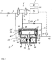
- Fig. 1 shows a schematic circuit diagram of a preferred embodiment of an electropneumatic parking brake control device 1 according to the invention.
- the electropneumatic parking brake control device 1 preferably represents a control device of an electropneumatic parking brake device of a towing vehicle-trailer combination and is arranged on the towing vehicle.
- the electropneumatic parking brake control device 1 has a supply connection 2 which is protected by a check valve 4. From the supply connection 2, a supply line 6 extends on the one hand to a first solenoid valve device 8 with a first 2/2-way solenoid valve 10 as an inlet valve and a second 2/2-way solenoid valve 12 as an outlet valve.
- the first 2/2-way solenoid valve 10 is, like the second 2/2-way solenoid valve 12, in the non-energized position shown, while both valves 10, 12, when energized, switch to the open position and are controlled by an electronic control device 14.
- a supply input 16 of a relay valve is also connected to the supply connection 2 via the supply line 6.
- a pneumatic control input 20 of the relay valve 18 is connected via a control line 22 to the combination of inlet valve 10 (first 2/2-way solenoid valve) and outlet valve 12 (second 2/2-way solenoid valve).
- the connection between the control line 22 or the control input 20 of the relay valve 18 and a pressure sink 24 is interrupted, while this connection is switched in the energized open position.
- the connection between the control line 22 or the control input 20 of the relay valve 18 and the supply connection 2 is interrupted, while this connection is switched in the energized open position.
- a first throttle element 30 is connected in a feedback line 26 between a work output 28 of the relay valve 18 and the control input 20 of the relay valve 18, through which the flow cross-section of the feedback line 26 narrows and, by means of the flow cross-section constriction, the air mass flow between the work output and the pneumatic control input of the relay valve is limited or throttled.
- the two 2/2-way solenoid valves 10, 12 are preferably spring-loaded into their currentless position and are switched over by energization by means of the control device 14.
- the working output 28 of the relay valve 18 is connected by means of a working line 38 to a connection 40 for at least one spring brake cylinder.
- Two spring brake cylinders (not shown here) on the rear axle are preferably connected to this connection 40.
- the control line 22 or the control input 20 of the relay valve 18 is pressurized or vented depending on the switching position of the first 2/2-way solenoid valve 10 and the second 2/2-way solenoid valve 12 (inlet / outlet solenoid valve combination), so that ventilation by increasing the amount of air by means of the relay valve 18, a corresponding ventilation of the work outlet 28 and thus of the connection 40 for the at least one spring-loaded brake cylinder results.
- the relay valve 18 is initially constructed in a largely known manner and includes a control chamber 42 connected to the control line via the control input 20, a relay piston 46 which delimits the control chamber 42 and is movable in a housing 44 with a valve body formed on the relay piston 46 or on its relay valve piston rod 48, which forms an outlet valve of a double seat valve with an outlet seat 50 on a sleeve 52 also movably received in the housing 44.
- the relay valve 18 also includes an inlet seat 54 formed on the housing 44, against which the cuff 52 is pretensioned and, together with this, forms an inlet valve of the double seat valve.
- the cuff 52 also has a central through-hole which, when the relay piston 46 is lifted from the cuff 52, connects a vent 56 to a working chamber 58 which is connected to the working outlet 28 in order to vent the latter.
- a storage chamber 60 which is in communication with the storage inlet 16 is connected to the working chamber 58 when the cuff 52 is lifted from the inlet seat 54 in order to ventilate the working outlet 28.
- the position of the relay piston 46, which with its valve body 48 can press the cuff 52 downward in order to lift it off the inlet seat 54, is accordingly determined by the pressure at the control input 20 or in the control chamber 42.
- the cuff 52 is urged against the inlet seat 54 by means of a cuff spring 62.
- a relay piston spring 64 with the force F F urges the relay piston 46 away from the outlet seat 50 in the direction of the control chamber 42.
- the switching states of the two 2/2-way solenoid valves 10, 12 are determined by the control device 14, in particular as a function of the parking brake signals present at the parking brake signal connection 32.
- the parking brake signal generator 36 is designed so that it modulates parking brake signals as a function of the actuation, which represent the operating states described below.
- the control device can also be connected to a vehicle data bus, not shown in the figures, via the parking brake signal connection or via a further signal connection, via which digital data can be received by and sent to other control devices.
- parking brake signals can also be fed into the control device 14 by a further control device, for example via a vehicle data bus, for example by a driver assistance system such as a traction help system on inclines.
- parking brake signals can then be generated by the control device 14 itself.
- the parking brake can be applied automatically when the vehicle has come to a standstill, or it can also be automatically released when it is recognized that the vehicle should start moving.
- the functioning of the electromagnetic parking brake control device 1 is as follows: In the in Fig. 1 Both the first 2/2-way solenoid valve 10 and the second 2/2-way solenoid valve 12 are de-energized, so that the control input 20 is always connected to the work output 28 of the relay valve 18 via the first throttle element 30. The feedback is thus stable and no compressed air can reach the control input 20 of the relay valve 18 from the supply connection 2 or escape from it to the pressure sink 24. So will the pressure currently prevailing at connection 40 for the at least one spring-loaded brake cylinder and thereby also its application or release position is kept constant.
- the first 2/2 Directional solenoid valve 10 this is switched into the through position and thereby the pressure in the control chamber 42 of the relay valve 18 is increased. This takes place in particular by pulsing the first 2/2-way solenoid valve 10.
- the relay piston 46 then moves downward, opens the inlet seat 54 of the double seat valve and allows supply pressure to flow into the working chamber 58.
- the relay piston 46 then moves back into a neutral position in which the inlet seat 54 and outlet seat 50 of the double seat valve are closed.
- a lower pressure at connection 40 for the at least one spring-loaded brake cylinder is to be regulated, preferably by pulsing the second 2/2 Directional solenoid valve 12, the control pressure in the control chamber 42 is lowered.
- the relay piston 46 then moves in the direction of the control chamber 42 and vents the working chamber 58 via the outlet seat 50 of the double seat valve until there is an equilibrium of forces again, whereupon the relay piston 46 returns to the neutral position.
- the first 2/2-way solenoid valve 10 is energized, for example, over a longer period of time.
- the control chamber 42 is ventilated, even if initially a small part of the air directed from the first 2/2-way solenoid valve 10 to the control chamber flows through the throttle element (30) into the working chamber. Then the pressure in the working chamber 58 rises faster than in the control chamber 42 until it finally exceeds it. Air then flows over the feedback line 26 and the first throttle element 30 from the working chamber 58 into the control chamber 42, so that the process intensifies itself.
- the relay piston 46 is pushed stably into its lower end position facing the working chamber 58, so that it permanently opens the inlet seat 54 of the double seat valve and connects the working chamber 58 to the supply port 2.
- the first 2/2-way solenoid valve 10 can also be relieved of flow in order to switch it into its blocking position.
- the second 2/2-way solenoid valve 12 is energized for a certain period of time. As a result, the control chamber 42 is vented until there is atmospheric pressure. Then moved the relay piston 46 moves in the direction of the control chamber 42 and vents the working chamber 58 via the outlet seat 50 of the double seat valve.
- the relay piston spring 64 loading the relay piston 46 ensures that it moves into its upper end position and remains there, as a result of which the outlet seat 50 is permanently fully open. Since the control chamber 42 is now permanently connected to the atmosphere via the throttle element 30, the working chamber 58 and the open outlet seat 50, the second 2/2-way solenoid valve 12 can be vented and thus brought into its blocking position.
- a second throttle element 65 is provided so that in the event of a power failure while an emergency or auxiliary braking function is being carried out, the "parking" state can be assumed in a stable manner. This ensures that in the event of a power failure during the execution of the emergency or auxiliary brake function, the control pressure in the control chamber 42 of the relay valve 18 drops, which also reduces the brake pressure in the spring-loaded brakes and consequently the "parking" state can be assumed in a stable manner.
- the second throttle element 65 is preferably formed by a radial through hole in an outer jacket wall 68 of the relay piston 46.
- the diameter of the through-hole represents the flow or throttle cross-section of the second throttle element 65.
- several through-holes can be provided in the jacket wall 68, for example distributed over the circumference.
- the third throttle element 66 is preferably formed by a plurality of radial through bores in the outer jacket wall 68 that are distributed around the circumference of the jacket wall 68 of the relay piston 46. It represents the sum of the diameter of the Through-bores represent the flow or throttle cross-section of the third throttle element 66. Instead of several smaller through-bores 66, only a single larger through-bore can be provided in the jacket wall 68.
- the second throttle element 65 and the third throttle element 66 are arranged one behind the other.
- an element 67 fixed to the relay valve housing 44 which cooperates with the second throttle element 65 and with the third throttle element 66 in such a way that, depending on the position of the relay piston 46 within the relay valve housing 44, the control chamber 42 via the second throttle element 65 and via the third throttle element 66 is connected to the vent 56 or such a connection is blocked.
- the element fixed on the relay valve housing 44 is formed here, for example, by a relay piston seal 67, against which the jacket wall 68 of the relay piston 46 seals.
- the flow cross section provided by the second throttle element 65 is smaller than the flow cross section provided by the first throttle element 30.
- the ventilation position shown of the relay piston 46 is characterized in that the inlet seat 54 is completely open and the outlet seat 50 is completely closed and a pressure is therefore applied to the connection 40 for the at least one spring brake cylinder which corresponds to a release pressure of the at least one spring brake cylinder corresponds to in which this is completely resolved.
- the intermediate position shown of the relay piston 46 is characterized in that a pressure is present at the connection 40 for the at least one spring brake cylinder which is greater than the application pressure but less than the release pressure
- FIG Figures 1 to 4 shows arranged below the through-hole, which forms the second throttle element 65, that a flow connection between the control chamber 42 and the vent 56 via the third throttle element 66 and transverse bore 76 as indicated by the arrow 78 in FIG Fig. 2 illustrated can only come about in the venting position of the relay piston 46, which corresponds to the "parking" state.
- the flow cross-section provided by the third throttle element 66 is also larger than the flow cross-section provided by the first throttle element 30, in the "parking" state, ie in the venting position of the relay piston 46, an unintentional release of the applied parking brake in the event of leaks, for example of the inlet valve (first 2/2-way solenoid valve) 10 can be avoided.
- a control of a trailer control valve is provided by means of the electropneumatic parking brake control device 1, this can be carried out in such a way that the pressure present at the connection 40 for the at least one spring brake cylinder is simultaneously directed to a connection for a trailer control valve.
- the electronic control device 14 is designed to perform a target / actual comparison as part of a pressure control and / or a pressure plausibility check on the basis of a signal representing an actual pressure and a parking brake signal representing a value for a target pressure and / or a determination of the supply pressure present at the supply connection 2 is carried out.
- a pressure sensor 88 is connected to the work output 28 of the relay valve 18 and thus also connectable or connected to the connection 40 for the at least one spring brake cylinder or to the connection 66 for the trailer control valve, the actual pressure and, from this, the operating state can be used there of the at least one spring brake cylinder (released, applied or partially released or applied) can be determined. The same then also applies to the operating state of the trailer brakes, which can be determined from the actual pressure at the connection for the trailer control valve. Furthermore, a pressure control circuit can then be implemented in which the solenoid valve device 8 in conjunction with the relay valve 18 form the actuators. If only the pressure sensor 88 is used, however, the pressure regulator does not recognize pressure deviations until a deviation in the working output pressure of the relay valve 18 has already occurred. This can lead to increased compressed air consumption.
- a pressure sensor 89 is connected to the control input 20 of the relay valve, the actual pressure regulated by the first and second 2/2-way solenoid valve 10, 12 can be determined very quickly, which results in high dynamics of the pressure control loop.
- the operating state of the at least one spring-loaded brake cylinder (released, applied or partially released or applied) and the actual brake pressure prevailing there can also be determined, but with less accuracy compared to the use of the pressure sensor 88, since the response behavior and hysteresis of the relay valve 18 received as a mistake. The same then also applies to the operating state of the trailer brakes. It is particularly advantageous when using the pressure sensor 89 that the pressure regulator can regulate pressure deviations in the control chamber 42 so precisely that they do not yet lead to a pressure deviation at the working output of the relay valve.
- a first pressure sensor 88 is connected to the work output 28 and a second pressure sensor 89 is connected to the control input of the relay valve 18, this also enables error detection by means of a plausibility check.
- the actual pressure values of the first and second pressure sensors 88, 89 must be in a certain relationship to one another, depending on the operating state, taking certain tolerances into account. Error detection or error monitoring can be carried out quickly, completely and in several operating states.
- a faster pressure regulation with less compressed air consumption results than if only one pressure sensor 88 is arranged at the work output 28 of the relay valve 18 and a more precise pressure regulation of the work output pressure than if only one pressure sensor 89 is arranged at the control input 20 of the relay valve 18.
- the relay valve 18, the first solenoid valve device 8 (first and second 2/2-way solenoid valve 10, 12), the check valve 4, the first throttle element 30, the electronic control device 14 and the supply port 2, the port 40 for the at least one spring brake cylinder and the parking brake signal connection 32 can be formed in one structural unit, which here represents an expandable basic module.
- At least one pressure sensor 88 and / or 89 can furthermore be integrated into the basic module or the structural unit 92.
- the electrical and pneumatic lines connecting the components mentioned pneumatically or electrically to one another are also integrated into the structural unit.
- the structural unit or the basic module can have a single housing or consist of several housings or housing parts that are detachably or non-detachably connected to one another.
- electropneumatic parking brake control device with another electronically controlled vehicle system to form a structural unit can be advantageous, since a common electronic control device can be provided.
- the combination with an air treatment system offers advantages, since the supply line to the electropneumatic parking brake control device can also be omitted here.
Applications Claiming Priority (2)
| Application Number | Priority Date | Filing Date | Title |
|---|---|---|---|
| DE102017120691.4A DE102017120691A1 (de) | 2017-09-07 | 2017-09-07 | Elektropneumatische Parkbremssteuereinrichtung |
| PCT/EP2018/072885 WO2019048263A1 (de) | 2017-09-07 | 2018-08-24 | Elektropneumatische parkbremssteuereinrichtung und bremsanlage eines fahrzeugs |
Publications (2)
| Publication Number | Publication Date |
|---|---|
| EP3678909A1 EP3678909A1 (de) | 2020-07-15 |
| EP3678909B1 true EP3678909B1 (de) | 2021-10-20 |
Family
ID=63517848
Family Applications (1)
| Application Number | Title | Priority Date | Filing Date |
|---|---|---|---|
| EP18765576.6A Active EP3678909B1 (de) | 2017-09-07 | 2018-08-24 | Elektropneumatische parkbremssteuereinrichtung und bremsanlage eines fahrzeugs |
Country Status (8)
| Country | Link |
|---|---|
| US (1) | US11267447B2 (pt) |
| EP (1) | EP3678909B1 (pt) |
| JP (1) | JP6926323B2 (pt) |
| CN (1) | CN111065561B (pt) |
| BR (1) | BR112020003687A2 (pt) |
| DE (1) | DE102017120691A1 (pt) |
| RU (1) | RU2730735C1 (pt) |
| WO (1) | WO2019048263A1 (pt) |
Families Citing this family (9)
| Publication number | Priority date | Publication date | Assignee | Title |
|---|---|---|---|---|
| DE102018126312A1 (de) * | 2018-10-23 | 2020-04-23 | Wabco Gmbh | Elektropneumatische Bremssystemarchitektur ohne direkte pneumatische Betriebsbremsredundanz an der Hinterachse (1p1e) |
| US11718287B2 (en) * | 2020-12-09 | 2023-08-08 | Bendix Commercial Vehicle Systems Llc | Automated system and method for parking a commercial vehicle |
| DE102021103053B3 (de) * | 2021-02-10 | 2022-02-03 | Knorr-Bremse Systeme für Nutzfahrzeuge GmbH | Relaisventilvorrichtung und Bremsvorrichtung für ein Fahrzeug mit einer solchen Relaisventilvorrichtung |
| CN113175544A (zh) * | 2021-04-19 | 2021-07-27 | 瑞立集团瑞安汽车零部件有限公司 | 二位三通阀及基于二位三通阀的集成epb空气处理装置 |
| CN113212405A (zh) * | 2021-06-01 | 2021-08-06 | 中车青岛四方车辆研究所有限公司 | 一种机车后备制动装置及其控制方法、机车 |
| US11613315B1 (en) * | 2021-08-20 | 2023-03-28 | David M Regen | Jackknife prevention system |
| CN113665554B (zh) * | 2021-09-25 | 2022-04-22 | 山东交通学院 | 一种断气刹继动阀及其解冻控制方法 |
| CN114458644A (zh) * | 2021-11-04 | 2022-05-10 | 中国海洋石油集团有限公司 | 一种节能增压器的使用方法 |
| CN114407853A (zh) * | 2021-12-28 | 2022-04-29 | 武汉辅安科技有限公司 | 一种气压式电子驻车系统 |
Family Cites Families (13)
| Publication number | Priority date | Publication date | Assignee | Title |
|---|---|---|---|---|
| DE10247812C1 (de) | 2002-10-14 | 2003-10-30 | Knorr Bremse Systeme | Verfahren und Vorrichtung zum Belüften und Entlüften von Federspeicherzylindern sowie Feststellbremsanlage mit derartigen Federspeicherzylindern |
| DE102004024462A1 (de) * | 2004-05-14 | 2005-12-08 | Knorr-Bremse Systeme für Schienenfahrzeuge GmbH | Elektropneumatische Bremseinrichtung eines Schienenfahrzeugs mit durchgängigem Regelbereich |
| DE102006041012A1 (de) * | 2006-08-31 | 2008-03-06 | Wabco Gmbh | Ventileinheit, Bremssteuerungseinrichtung, Fahrzeugbremsanlage sowie Fahrzeug |
| DE102006055570B4 (de) | 2006-11-24 | 2010-05-06 | Knorr-Bremse Systeme für Nutzfahrzeuge GmbH | Feststellbremsvorrichtung mit einer Feststellbremse-Notlöseeinrichtung |
| DE102007061908B4 (de) | 2007-12-21 | 2010-01-28 | Knorr-Bremse Systeme für Nutzfahrzeuge GmbH | Parkbremse |
| DE102009016983A1 (de) | 2009-04-08 | 2010-10-21 | Knorr-Bremse Systeme für Nutzfahrzeuge GmbH | Pneumatisch gesteuertes 3/2-Wegeventil zur Steuerung einer pneumatischen Feststellbremse und Verfahren zum Betreiben eines pneumatisch gesteuerten 3/2-Wegeventils |
| DE102009059816B3 (de) | 2009-12-21 | 2011-04-28 | Knorr-Bremse Systeme für Nutzfahrzeuge GmbH | Elektrisch betätigbares Feststellbremssystem und Verfahren zum Steuern eines elektrisch betätigbaren Feststellbremssystems |
| DE102010021911B4 (de) * | 2010-05-28 | 2012-10-18 | Knorr-Bremse Systeme für Nutzfahrzeuge GmbH | Elektrisch betätigbares Feststellbremssystem und Verfahren zum Betreiben eines elektrisch betätigbaren Feststellbremssystems |
| DE102011101438B4 (de) | 2011-05-13 | 2013-05-08 | Knorr-Bremse Systeme für Nutzfahrzeuge GmbH | Parkbremseinrichtung |
| HUE037922T2 (hu) | 2014-04-09 | 2018-09-28 | Knorr Bremse Systeme Fuer Nutzfahrzeuge Gmbh | Elektropneumatikus parkolófékvezérlõ berendezés |
| DE102015107125B4 (de) | 2015-05-07 | 2022-01-05 | Knorr-Bremse Systeme für Nutzfahrzeuge GmbH | Vorrichtung zum Steuern einer Bremsanlage für ein Nutzfahrzeug und Bremsanlage |
| DE102015116317B4 (de) | 2015-09-28 | 2021-10-21 | Knorr-Bremse Systeme für Nutzfahrzeuge GmbH | Elektro-pneumatische Parkbremseinrichtung eines Fahrzeugs mit weiterem Steuerkreis und Zugfahrzeug mit elektro-pneumatischer Parkbremseinrichtung |
| DE102015118290A1 (de) * | 2015-10-27 | 2017-04-27 | Knorr-Bremse Systeme für Nutzfahrzeuge GmbH | Elektro-pneumatische Feststellbremseinrichtung mit redundanter pneumatischer Steuerung |
-
2017
- 2017-09-07 DE DE102017120691.4A patent/DE102017120691A1/de active Pending
-
2018
- 2018-08-24 RU RU2020112188A patent/RU2730735C1/ru active
- 2018-08-24 JP JP2020513742A patent/JP6926323B2/ja active Active
- 2018-08-24 BR BR112020003687-0A patent/BR112020003687A2/pt unknown
- 2018-08-24 CN CN201880057976.9A patent/CN111065561B/zh active Active
- 2018-08-24 EP EP18765576.6A patent/EP3678909B1/de active Active
- 2018-08-24 US US16/645,318 patent/US11267447B2/en active Active
- 2018-08-24 WO PCT/EP2018/072885 patent/WO2019048263A1/de unknown
Also Published As
| Publication number | Publication date |
|---|---|
| US11267447B2 (en) | 2022-03-08 |
| JP2020533221A (ja) | 2020-11-19 |
| US20210162972A1 (en) | 2021-06-03 |
| EP3678909A1 (de) | 2020-07-15 |
| WO2019048263A1 (de) | 2019-03-14 |
| BR112020003687A2 (pt) | 2020-09-01 |
| DE102017120691A1 (de) | 2019-03-07 |
| CN111065561A (zh) | 2020-04-24 |
| CN111065561B (zh) | 2022-04-05 |
| JP6926323B2 (ja) | 2021-08-25 |
| RU2730735C1 (ru) | 2020-08-25 |
Similar Documents
| Publication | Publication Date | Title |
|---|---|---|
| EP3678909B1 (de) | Elektropneumatische parkbremssteuereinrichtung und bremsanlage eines fahrzeugs | |
| EP3129264B1 (de) | Elektropneumatische parkbremssteuereinrichtung | |
| DE102015116317B4 (de) | Elektro-pneumatische Parkbremseinrichtung eines Fahrzeugs mit weiterem Steuerkreis und Zugfahrzeug mit elektro-pneumatischer Parkbremseinrichtung | |
| EP3341253B1 (de) | Elektrische parkbremseinrichtung mit zusätzlicher energieversorgung | |
| EP3507154B1 (de) | Elektronisch steuerbares pneumatisches bremssystem in einem nutzfahrzeug sowie verfahren zu dessen steuerung | |
| EP3368387B1 (de) | Elektro-pneumatische feststellbremseinrichtung mit redundanter pneumatischer steuerung | |
| DE102011101438B4 (de) | Parkbremseinrichtung | |
| EP3755589B1 (de) | Elektropneumatische ausrüstung eines fahrzeugs | |
| WO2008025400A1 (de) | Ventileinheit, bremssteuerungseinrichtung, fahrzeugbremsanlage sowie fahrzeug | |
| WO2009083108A2 (de) | Parkbremse | |
| WO2008061799A1 (de) | Feststellbremsvorrichtung mit einer feststellbremse-notlöseeinrichtung und -verfahren | |
| DE102014118943A1 (de) | Verfahren zur Steuerung einer elektropneumatischen Parkbremseinrichtung mit dynamischer Blockierverhinderung | |
| EP2298616A2 (de) | Steuergerät und Verfahren zum Testen einer Ventileinrichtung einer elektrischen Feststellbremse | |
| DE19918070B4 (de) | Druckregelvorrichtung für elektro-pneumatische Bremsanlagen von Fahrzeugen, insbesondere Nutzfahrzeugen | |
| EP3359432B1 (de) | Elektro-pneumatische bremseinrichtung mit einem über zwei rückschlagventile mit zwei druckluftvorräten verbundenen druckregelmodul | |
| DE4214547C2 (de) | Fahrzeugbremssystem | |
| DE102018110088A1 (de) | Steuerventil, elektronisch steuerbares Bremssystem sowie Verfahren zum Steuern des elektronisch steuerbaren Bremssystems | |
| WO2011110460A1 (de) | Vorrichtung zur steuerung von pneumatischen einrichtungen eines anhängers | |
| DE102014116732A1 (de) | Bremseinrichtung eines Fahrzeugs mit elektrischer und durch eine pneumatische Notzuspanneinrichtung zuspannbarer Feststellbremse | |
| DE202022106835U1 (de) | Elektropneumatische Parbremssteuereinrichtung | |
| DE2105564C3 (de) | Elektropneumatische Druckluftbremse für Schienenfahrzeuge | |
| DE3009273A1 (de) | Elektropneumatische druckluftbremse fuer fahrzeuge, insbesondere fuer schienenfahrzeuge | |
| EP1188635A2 (de) | Anhängerbremsventil für einen Anhänger mit elektronischer Bremsregelung |
Legal Events
| Date | Code | Title | Description |
|---|---|---|---|
| STAA | Information on the status of an ep patent application or granted ep patent |
Free format text: STATUS: UNKNOWN |
|
| STAA | Information on the status of an ep patent application or granted ep patent |
Free format text: STATUS: THE INTERNATIONAL PUBLICATION HAS BEEN MADE |
|
| PUAI | Public reference made under article 153(3) epc to a published international application that has entered the european phase |
Free format text: ORIGINAL CODE: 0009012 |
|
| STAA | Information on the status of an ep patent application or granted ep patent |
Free format text: STATUS: REQUEST FOR EXAMINATION WAS MADE |
|
| 17P | Request for examination filed |
Effective date: 20200407 |
|
| AK | Designated contracting states |
Kind code of ref document: A1 Designated state(s): AL AT BE BG CH CY CZ DE DK EE ES FI FR GB GR HR HU IE IS IT LI LT LU LV MC MK MT NL NO PL PT RO RS SE SI SK SM TR |
|
| AX | Request for extension of the european patent |
Extension state: BA ME |
|
| DAV | Request for validation of the european patent (deleted) | ||
| DAX | Request for extension of the european patent (deleted) | ||
| RIC1 | Information provided on ipc code assigned before grant |
Ipc: B60T 15/02 20060101ALI20210324BHEP Ipc: B60T 13/70 20060101ALI20210324BHEP Ipc: B60T 13/38 20060101ALI20210324BHEP Ipc: B60T 13/26 20060101ALI20210324BHEP Ipc: B60T 17/18 20060101ALI20210324BHEP Ipc: B60T 15/04 20060101ALI20210324BHEP Ipc: B60T 13/68 20060101AFI20210324BHEP |
|
| GRAP | Despatch of communication of intention to grant a patent |
Free format text: ORIGINAL CODE: EPIDOSNIGR1 |
|
| STAA | Information on the status of an ep patent application or granted ep patent |
Free format text: STATUS: GRANT OF PATENT IS INTENDED |
|
| INTG | Intention to grant announced |
Effective date: 20210506 |
|
| GRAS | Grant fee paid |
Free format text: ORIGINAL CODE: EPIDOSNIGR3 |
|
| GRAA | (expected) grant |
Free format text: ORIGINAL CODE: 0009210 |
|
| STAA | Information on the status of an ep patent application or granted ep patent |
Free format text: STATUS: THE PATENT HAS BEEN GRANTED |
|
| AK | Designated contracting states |
Kind code of ref document: B1 Designated state(s): AL AT BE BG CH CY CZ DE DK EE ES FI FR GB GR HR HU IE IS IT LI LT LU LV MC MK MT NL NO PL PT RO RS SE SI SK SM TR |
|
| REG | Reference to a national code |
Ref country code: GB Ref legal event code: FG4D Free format text: NOT ENGLISH |
|
| REG | Reference to a national code |
Ref country code: CH Ref legal event code: EP |
|
| REG | Reference to a national code |
Ref country code: IE Ref legal event code: FG4D Free format text: LANGUAGE OF EP DOCUMENT: GERMAN |
|
| REG | Reference to a national code |
Ref country code: DE Ref legal event code: R096 Ref document number: 502018007526 Country of ref document: DE |
|
| REG | Reference to a national code |
Ref country code: AT Ref legal event code: REF Ref document number: 1439695 Country of ref document: AT Kind code of ref document: T Effective date: 20211115 |
|
| REG | Reference to a national code |
Ref country code: SE Ref legal event code: TRGR |
|
| REG | Reference to a national code |
Ref country code: LT Ref legal event code: MG9D |
|
| REG | Reference to a national code |
Ref country code: NL Ref legal event code: MP Effective date: 20211020 |
|
| PG25 | Lapsed in a contracting state [announced via postgrant information from national office to epo] |
Ref country code: RS Free format text: LAPSE BECAUSE OF FAILURE TO SUBMIT A TRANSLATION OF THE DESCRIPTION OR TO PAY THE FEE WITHIN THE PRESCRIBED TIME-LIMIT Effective date: 20211020 Ref country code: LT Free format text: LAPSE BECAUSE OF FAILURE TO SUBMIT A TRANSLATION OF THE DESCRIPTION OR TO PAY THE FEE WITHIN THE PRESCRIBED TIME-LIMIT Effective date: 20211020 Ref country code: FI Free format text: LAPSE BECAUSE OF FAILURE TO SUBMIT A TRANSLATION OF THE DESCRIPTION OR TO PAY THE FEE WITHIN THE PRESCRIBED TIME-LIMIT Effective date: 20211020 Ref country code: BG Free format text: LAPSE BECAUSE OF FAILURE TO SUBMIT A TRANSLATION OF THE DESCRIPTION OR TO PAY THE FEE WITHIN THE PRESCRIBED TIME-LIMIT Effective date: 20220120 |
|
| PG25 | Lapsed in a contracting state [announced via postgrant information from national office to epo] |
Ref country code: IS Free format text: LAPSE BECAUSE OF FAILURE TO SUBMIT A TRANSLATION OF THE DESCRIPTION OR TO PAY THE FEE WITHIN THE PRESCRIBED TIME-LIMIT Effective date: 20220220 Ref country code: PT Free format text: LAPSE BECAUSE OF FAILURE TO SUBMIT A TRANSLATION OF THE DESCRIPTION OR TO PAY THE FEE WITHIN THE PRESCRIBED TIME-LIMIT Effective date: 20220221 Ref country code: PL Free format text: LAPSE BECAUSE OF FAILURE TO SUBMIT A TRANSLATION OF THE DESCRIPTION OR TO PAY THE FEE WITHIN THE PRESCRIBED TIME-LIMIT Effective date: 20211020 Ref country code: NO Free format text: LAPSE BECAUSE OF FAILURE TO SUBMIT A TRANSLATION OF THE DESCRIPTION OR TO PAY THE FEE WITHIN THE PRESCRIBED TIME-LIMIT Effective date: 20220120 Ref country code: NL Free format text: LAPSE BECAUSE OF FAILURE TO SUBMIT A TRANSLATION OF THE DESCRIPTION OR TO PAY THE FEE WITHIN THE PRESCRIBED TIME-LIMIT Effective date: 20211020 Ref country code: LV Free format text: LAPSE BECAUSE OF FAILURE TO SUBMIT A TRANSLATION OF THE DESCRIPTION OR TO PAY THE FEE WITHIN THE PRESCRIBED TIME-LIMIT Effective date: 20211020 Ref country code: HR Free format text: LAPSE BECAUSE OF FAILURE TO SUBMIT A TRANSLATION OF THE DESCRIPTION OR TO PAY THE FEE WITHIN THE PRESCRIBED TIME-LIMIT Effective date: 20211020 Ref country code: GR Free format text: LAPSE BECAUSE OF FAILURE TO SUBMIT A TRANSLATION OF THE DESCRIPTION OR TO PAY THE FEE WITHIN THE PRESCRIBED TIME-LIMIT Effective date: 20220121 Ref country code: ES Free format text: LAPSE BECAUSE OF FAILURE TO SUBMIT A TRANSLATION OF THE DESCRIPTION OR TO PAY THE FEE WITHIN THE PRESCRIBED TIME-LIMIT Effective date: 20211020 |
|
| REG | Reference to a national code |
Ref country code: DE Ref legal event code: R097 Ref document number: 502018007526 Country of ref document: DE |
|
| PG25 | Lapsed in a contracting state [announced via postgrant information from national office to epo] |
Ref country code: SM Free format text: LAPSE BECAUSE OF FAILURE TO SUBMIT A TRANSLATION OF THE DESCRIPTION OR TO PAY THE FEE WITHIN THE PRESCRIBED TIME-LIMIT Effective date: 20211020 Ref country code: SK Free format text: LAPSE BECAUSE OF FAILURE TO SUBMIT A TRANSLATION OF THE DESCRIPTION OR TO PAY THE FEE WITHIN THE PRESCRIBED TIME-LIMIT Effective date: 20211020 Ref country code: RO Free format text: LAPSE BECAUSE OF FAILURE TO SUBMIT A TRANSLATION OF THE DESCRIPTION OR TO PAY THE FEE WITHIN THE PRESCRIBED TIME-LIMIT Effective date: 20211020 Ref country code: EE Free format text: LAPSE BECAUSE OF FAILURE TO SUBMIT A TRANSLATION OF THE DESCRIPTION OR TO PAY THE FEE WITHIN THE PRESCRIBED TIME-LIMIT Effective date: 20211020 Ref country code: DK Free format text: LAPSE BECAUSE OF FAILURE TO SUBMIT A TRANSLATION OF THE DESCRIPTION OR TO PAY THE FEE WITHIN THE PRESCRIBED TIME-LIMIT Effective date: 20211020 Ref country code: CZ Free format text: LAPSE BECAUSE OF FAILURE TO SUBMIT A TRANSLATION OF THE DESCRIPTION OR TO PAY THE FEE WITHIN THE PRESCRIBED TIME-LIMIT Effective date: 20211020 |
|
| PLBE | No opposition filed within time limit |
Free format text: ORIGINAL CODE: 0009261 |
|
| STAA | Information on the status of an ep patent application or granted ep patent |
Free format text: STATUS: NO OPPOSITION FILED WITHIN TIME LIMIT |
|
| 26N | No opposition filed |
Effective date: 20220721 |
|
| PG25 | Lapsed in a contracting state [announced via postgrant information from national office to epo] |
Ref country code: AL Free format text: LAPSE BECAUSE OF FAILURE TO SUBMIT A TRANSLATION OF THE DESCRIPTION OR TO PAY THE FEE WITHIN THE PRESCRIBED TIME-LIMIT Effective date: 20211020 |
|
| PG25 | Lapsed in a contracting state [announced via postgrant information from national office to epo] |
Ref country code: SI Free format text: LAPSE BECAUSE OF FAILURE TO SUBMIT A TRANSLATION OF THE DESCRIPTION OR TO PAY THE FEE WITHIN THE PRESCRIBED TIME-LIMIT Effective date: 20211020 |
|
| PG25 | Lapsed in a contracting state [announced via postgrant information from national office to epo] |
Ref country code: MC Free format text: LAPSE BECAUSE OF FAILURE TO SUBMIT A TRANSLATION OF THE DESCRIPTION OR TO PAY THE FEE WITHIN THE PRESCRIBED TIME-LIMIT Effective date: 20211020 |
|
| REG | Reference to a national code |
Ref country code: CH Ref legal event code: PL |
|
| PG25 | Lapsed in a contracting state [announced via postgrant information from national office to epo] |
Ref country code: LU Free format text: LAPSE BECAUSE OF NON-PAYMENT OF DUE FEES Effective date: 20220824 Ref country code: LI Free format text: LAPSE BECAUSE OF NON-PAYMENT OF DUE FEES Effective date: 20220831 Ref country code: CH Free format text: LAPSE BECAUSE OF NON-PAYMENT OF DUE FEES Effective date: 20220831 |
|
| REG | Reference to a national code |
Ref country code: BE Ref legal event code: MM Effective date: 20220831 |
|
| PG25 | Lapsed in a contracting state [announced via postgrant information from national office to epo] |
Ref country code: IT Free format text: LAPSE BECAUSE OF FAILURE TO SUBMIT A TRANSLATION OF THE DESCRIPTION OR TO PAY THE FEE WITHIN THE PRESCRIBED TIME-LIMIT Effective date: 20211020 |
|
| P01 | Opt-out of the competence of the unified patent court (upc) registered |
Effective date: 20230607 |
|
| PG25 | Lapsed in a contracting state [announced via postgrant information from national office to epo] |
Ref country code: IE Free format text: LAPSE BECAUSE OF NON-PAYMENT OF DUE FEES Effective date: 20220824 |
|
| PG25 | Lapsed in a contracting state [announced via postgrant information from national office to epo] |
Ref country code: BE Free format text: LAPSE BECAUSE OF NON-PAYMENT OF DUE FEES Effective date: 20220831 |
|
| PGFP | Annual fee paid to national office [announced via postgrant information from national office to epo] |
Ref country code: GB Payment date: 20230824 Year of fee payment: 6 |
|
| PGFP | Annual fee paid to national office [announced via postgrant information from national office to epo] |
Ref country code: SE Payment date: 20230823 Year of fee payment: 6 Ref country code: FR Payment date: 20230821 Year of fee payment: 6 Ref country code: DE Payment date: 20230822 Year of fee payment: 6 |
|
| PG25 | Lapsed in a contracting state [announced via postgrant information from national office to epo] |
Ref country code: CY Free format text: LAPSE BECAUSE OF FAILURE TO SUBMIT A TRANSLATION OF THE DESCRIPTION OR TO PAY THE FEE WITHIN THE PRESCRIBED TIME-LIMIT Effective date: 20211020 |