EP1188635A2 - Anhängerbremsventil für einen Anhänger mit elektronischer Bremsregelung - Google Patents
Anhängerbremsventil für einen Anhänger mit elektronischer Bremsregelung Download PDFInfo
- Publication number
- EP1188635A2 EP1188635A2 EP01120605A EP01120605A EP1188635A2 EP 1188635 A2 EP1188635 A2 EP 1188635A2 EP 01120605 A EP01120605 A EP 01120605A EP 01120605 A EP01120605 A EP 01120605A EP 1188635 A2 EP1188635 A2 EP 1188635A2
- Authority
- EP
- European Patent Office
- Prior art keywords
- valve
- pressure
- connection
- brake
- slide
- Prior art date
- Legal status (The legal status is an assumption and is not a legal conclusion. Google has not performed a legal analysis and makes no representation as to the accuracy of the status listed.)
- Granted
Links
Images


Classifications
-
- B—PERFORMING OPERATIONS; TRANSPORTING
- B60—VEHICLES IN GENERAL
- B60T—VEHICLE BRAKE CONTROL SYSTEMS OR PARTS THEREOF; BRAKE CONTROL SYSTEMS OR PARTS THEREOF, IN GENERAL; ARRANGEMENT OF BRAKING ELEMENTS ON VEHICLES IN GENERAL; PORTABLE DEVICES FOR PREVENTING UNWANTED MOVEMENT OF VEHICLES; VEHICLE MODIFICATIONS TO FACILITATE COOLING OF BRAKES
- B60T15/00—Construction arrangement, or operation of valves incorporated in power brake systems and not covered by groups B60T11/00 or B60T13/00
- B60T15/02—Application and release valves
- B60T15/18—Triple or other relay valves which allow step-wise application or release and which are actuated by brake-pipe pressure variation to connect brake cylinders or equivalent to compressed air or vacuum source or atmosphere
- B60T15/24—Triple or other relay valves which allow step-wise application or release and which are actuated by brake-pipe pressure variation to connect brake cylinders or equivalent to compressed air or vacuum source or atmosphere controlled by three fluid pressures
- B60T15/243—Trailer control valves
-
- B—PERFORMING OPERATIONS; TRANSPORTING
- B60—VEHICLES IN GENERAL
- B60T—VEHICLE BRAKE CONTROL SYSTEMS OR PARTS THEREOF; BRAKE CONTROL SYSTEMS OR PARTS THEREOF, IN GENERAL; ARRANGEMENT OF BRAKING ELEMENTS ON VEHICLES IN GENERAL; PORTABLE DEVICES FOR PREVENTING UNWANTED MOVEMENT OF VEHICLES; VEHICLE MODIFICATIONS TO FACILITATE COOLING OF BRAKES
- B60T15/00—Construction arrangement, or operation of valves incorporated in power brake systems and not covered by groups B60T11/00 or B60T13/00
- B60T15/02—Application and release valves
- B60T15/025—Electrically controlled valves
- B60T15/027—Electrically controlled valves in pneumatic systems
-
- B—PERFORMING OPERATIONS; TRANSPORTING
- B60—VEHICLES IN GENERAL
- B60T—VEHICLE BRAKE CONTROL SYSTEMS OR PARTS THEREOF; BRAKE CONTROL SYSTEMS OR PARTS THEREOF, IN GENERAL; ARRANGEMENT OF BRAKING ELEMENTS ON VEHICLES IN GENERAL; PORTABLE DEVICES FOR PREVENTING UNWANTED MOVEMENT OF VEHICLES; VEHICLE MODIFICATIONS TO FACILITATE COOLING OF BRAKES
- B60T17/00—Component parts, details, or accessories of power brake systems not covered by groups B60T8/00, B60T13/00 or B60T15/00, or presenting other characteristic features
- B60T17/18—Safety devices; Monitoring
-
- B—PERFORMING OPERATIONS; TRANSPORTING
- B60—VEHICLES IN GENERAL
- B60T—VEHICLE BRAKE CONTROL SYSTEMS OR PARTS THEREOF; BRAKE CONTROL SYSTEMS OR PARTS THEREOF, IN GENERAL; ARRANGEMENT OF BRAKING ELEMENTS ON VEHICLES IN GENERAL; PORTABLE DEVICES FOR PREVENTING UNWANTED MOVEMENT OF VEHICLES; VEHICLE MODIFICATIONS TO FACILITATE COOLING OF BRAKES
- B60T8/00—Arrangements for adjusting wheel-braking force to meet varying vehicular or ground-surface conditions, e.g. limiting or varying distribution of braking force
- B60T8/32—Arrangements for adjusting wheel-braking force to meet varying vehicular or ground-surface conditions, e.g. limiting or varying distribution of braking force responsive to a speed condition, e.g. acceleration or deceleration
- B60T8/321—Arrangements for adjusting wheel-braking force to meet varying vehicular or ground-surface conditions, e.g. limiting or varying distribution of braking force responsive to a speed condition, e.g. acceleration or deceleration deceleration
- B60T8/323—Systems specially adapted for tractor-trailer combinations
-
- B—PERFORMING OPERATIONS; TRANSPORTING
- B60—VEHICLES IN GENERAL
- B60T—VEHICLE BRAKE CONTROL SYSTEMS OR PARTS THEREOF; BRAKE CONTROL SYSTEMS OR PARTS THEREOF, IN GENERAL; ARRANGEMENT OF BRAKING ELEMENTS ON VEHICLES IN GENERAL; PORTABLE DEVICES FOR PREVENTING UNWANTED MOVEMENT OF VEHICLES; VEHICLE MODIFICATIONS TO FACILITATE COOLING OF BRAKES
- B60T8/00—Arrangements for adjusting wheel-braking force to meet varying vehicular or ground-surface conditions, e.g. limiting or varying distribution of braking force
- B60T8/32—Arrangements for adjusting wheel-braking force to meet varying vehicular or ground-surface conditions, e.g. limiting or varying distribution of braking force responsive to a speed condition, e.g. acceleration or deceleration
- B60T8/321—Arrangements for adjusting wheel-braking force to meet varying vehicular or ground-surface conditions, e.g. limiting or varying distribution of braking force responsive to a speed condition, e.g. acceleration or deceleration deceleration
- B60T8/3255—Systems in which the braking action is dependent on brake pedal data
- B60T8/327—Pneumatic systems
-
- B—PERFORMING OPERATIONS; TRANSPORTING
- B60—VEHICLES IN GENERAL
- B60T—VEHICLE BRAKE CONTROL SYSTEMS OR PARTS THEREOF; BRAKE CONTROL SYSTEMS OR PARTS THEREOF, IN GENERAL; ARRANGEMENT OF BRAKING ELEMENTS ON VEHICLES IN GENERAL; PORTABLE DEVICES FOR PREVENTING UNWANTED MOVEMENT OF VEHICLES; VEHICLE MODIFICATIONS TO FACILITATE COOLING OF BRAKES
- B60T8/00—Arrangements for adjusting wheel-braking force to meet varying vehicular or ground-surface conditions, e.g. limiting or varying distribution of braking force
- B60T8/32—Arrangements for adjusting wheel-braking force to meet varying vehicular or ground-surface conditions, e.g. limiting or varying distribution of braking force responsive to a speed condition, e.g. acceleration or deceleration
- B60T8/34—Arrangements for adjusting wheel-braking force to meet varying vehicular or ground-surface conditions, e.g. limiting or varying distribution of braking force responsive to a speed condition, e.g. acceleration or deceleration having a fluid pressure regulator responsive to a speed condition
- B60T8/349—Systems adapted to control a set of axles, e.g. tandem axles
Definitions
- the invention relates to a trailer brake valve according to the preamble of claim 1.
- Such a trailer brake valve is from the DE 28 10 850 A1 known.
- the function is still one Advance of the transmitted to the brake cylinder Brake pressure compared to the pneumatic brake signal integrated.
- DE 30 31 105 A1 describes a load-dependent system Two-line trailer braking system known from a Emergency brake valve constructed as a seat valve [there (3)] and a load-controlled brake force regulator [there (5)], which is a combination of a load-dependent control section with an air volume boosting Relay valve is formed.
- the function of the emergency brake valve corresponds to that Demolition function in a conventional trailer brake valve, see above that the function of both valves is analogous to the function of a trailer brake valve with load-controlled Brake force control can be understood. This is especially true since there is also a trailer brake valve z. B.
- EP 0 586 203 B1 discloses an electronic brake control for a trailer in the form of a configuration of valves with their control by an electronic Control means; here are as possible alternatives different valve configurations for conceptually different variants of the control device described.
- the writing shows pneumatic Circuits for typical functions of a trailer brake valve with different control device variants [there z. B. emergency transducer valve (119) in the further and fluid energy supply means (136) in the narrow Sense]. Notes on constructive design such valve devices for EBS systems are in the writing does not contain.
- a trailer with electronic brake control becomes the regulation of the brake pressure in the brake cylinders a vehicle axle of the intended one Brake control electronics made, which also z. B. in In the case of an ABS control intervention with different Friction on both sides of the vehicle Brake pressure in the brake cylinders on the left side of the vehicle different from the brake pressure in the Brake cylinders on the right side of the vehicle.
- the brake pressure from the brake control electronics z. B. varies depending on the load. For such a load-dependent braking becomes the load z. B. determined via a pressure measurement in an air bag and the brake control electronics communicated which then the brake pressure in the trailer's brake cylinders modified accordingly.
- a brake pressure modulator which consists of electrically controllable valves, which is usually in clocked mode of operation
- Brake control electronics can be controlled and used as pilot valves to generate a control pressure in the control chamber serve a relay valve, which the control pressure air volume boosted as braking pressure above its Outputs output to one or more brake cylinders; one or more of such a structure can be used Brake control channels can be implemented.
- a trailer brake valve for use in a trailer with electronic brake control therefore does not need about the function of air volume amplification yet via special functions such as B. the function mentioned an advance or that of a load-dependent modification the brake pressure.
- B the function mentioned an advance or that of a load-dependent modification the brake pressure.
- the basic functions namely the provision the braking pressure transferred from the towing vehicle, the tear-off protection and the possibility of connection of release valves [for the release of the decoupled State of braked axes] are realized.
- the invention is therefore based on the object for a trailer brake valve according to the first known scripture to specify a valve construction that accordingly the reduced requirements of use of the trailer brake valve in a trailer with electronic Brake control is simplified so that Manufacturing costs of the trailer brake valve reduced are.
- the invention has the advantage that the susceptibility to errors by the essential compared to the prior art simplified structure is significantly reduced.
- Relay valves are by venting the relay valve pressure chamber not free of air consumption.
- Eliminate an air volume boosting according to the relay valve principle working valve device after The invention has the advantage that no air consumption more takes place and that with an air consumption associated noise also does not take place.
- the omission of a relay valve means that Relay piston hysteresis, firstly to the advantage of a improved accuracy and secondly to the benefit leads to no delayed response of the modulated Pressure versus the set pressure there is more.
- the response pressure had to be at Hours. T. first of all from the pneumatic brake signal exceeded so that the pneumatic brake signal air volume can be controlled.
- a development of the invention has the advantage that by the elimination of the relay valve with its time delay "Output-input" from i. Gen. more than 30 ms a time advantage for the electrical signal of the Pressure sensor is connected because this pressure sensor brake pressure output from the trailer brake valve.
- the pneumatic is strongly generalized in the invention Path optimized because this is in contrast to the normally effective electrical brake signal transmission is only intended for emergency braking where there is no load-dependent brake pressure influence can be.
- the optimized pneumatic path there is the advantage that on the one hand air-consuming Facilities are eliminated and, on the other hand, time delays no longer occur due to such devices.
- Another development of the invention has the advantage that switching the trailer brake valve in the demolition position only from the supply connection of the Valve [this is pneumatic with the red coupling head connected] depends on the applied pressure.
- the Transition from one switch position to the other takes place also suddenly, so that the shift is also friction-independent takes place and creeping transitions avoided become.
- the supply line is broken the emergency braking "immediately" and it has to be conventional Solutions do not drive through a characteristic curve at first become.
- the valve is pressure balanced Valve with positive overlap; across from This training also has conventional solutions the advantage that breathing rooms and the associated Icing hazards can be avoided.
- 1 is the configuration based on a basic variant for trailer EBS systems, which consists of a semi-trailer (34) with two Axes exist, this is a 2S / 2M system [two ABS sensors for two wheels and two modulator channels for the left and right wheel brakes Page]; the ABS brake pressure control is thus page by page carried out
- the trailer with the trailer brake valve according to the invention is pneumatic with the towing vehicle over two Pressure hoses, firstly a supply pressure hose (30) to transfer the supply pressure [Red pressure hose attached to the towing vehicle, the coupled via the "red coupling head” (48) of the trailer is] and secondly a brake pressure hose (31) for transmission of the brake pressure [on the towing vehicle attached yellow wire that goes over the "yellow Coupling head "(49) of the trailer is connected].
- a supply pressure hose to transfer the supply pressure [Red pressure hose attached to the towing vehicle, the coupled via the "red coupling head” (48) of the trailer is]
- secondly a brake pressure hose (31) for transmission of the brake pressure [on the towing vehicle attached yellow wire that goes over the "yellow Coupling head "(49) of the trailer is connected.
- red pressure hose On the side of the towing vehicle is both red pressure hose as well as the yellow pressure hose pneumatically to a trailer control valve [AST valve]
- the supply pressure hose is on the side of the trailer (30) pneumatically via a optional release valve (33) with the supply connection (1), and the brake pressure hose (31) via a Pneumatic line with the brake specification connection (4) of the Trailer brake valves (8) connected.
- the trailer brake valve (8) also has a tank connection (3) on which the storage pressure vessel (9) for the trailer is connected and via a brake pressure connection (2) at which the pneumatic brake pressure to the pneumatic input (28) of the pneumatic Brake pressure modulator (29) is output; this Brake pressure poses for the trailer with its electronic Brake pressure control represents the redundancy pressure.
- the trailer brake valve also (8) full brake pressure to the modulator (29) controlled by a purely pneumatic braking allowed without the help of electronics.
- the modulator (29) controlled by a purely pneumatic braking allowed without the help of electronics.
- the brake pressure modulator (29) also has a Pressure supply connection (35) through a pneumatic line connected to the supply pressure vessel (9) is.
- the brake pressure modulator (29) is electrical Connections controlled by the electronics unit (42).
- the pneumatic brake pressure modulator (29) is, for. B. as two-channel pressure control module according to DE 42 27 084 A1 [there Fig. 2] constructed; this scripture is as follows designated S1.
- a common 3/2 solenoid valve [there (12)] as a changeover valve for further channel-specific ventilation and bleed solenoid valves [there (9 ') and (7) or (9) and (8)] are provided, which in the case of EBS brake pressure control with an intermittent operating mode Control pilot brake pressures per channel, which in turn at control inputs [there (5) or (6)] of per channel provided relay valves [there (3) or (4)] are.
- the relay valve working ports [there (20) and (22) and (21) and (23)] are as in FIG.
- the pneumatic input (28) is with the control pressure connection [there (13)] and the pressure supply connection (35) is with the supply pressure connection [there (17)] of the Pressure control module connected after S1.
- the pressure supply connection (35) is with the supply pressure connection [there (17)] of the Pressure control module connected after S1.
- d. H. in its de-energized State is from the 3/2 solenoid valve [there (12)] S1 arriving at the pneumatic input (28) according to FIG. 1 Pressure to the control inputs of the relay valves [there (3), (4)] of the S1 controlled and increased air volume at the relay valve working connections mentioned output.
- This mode of operation corresponds the redundancy case in which a pneumatic redundancy pressure air volume increased to the brake cylinder without the electronics unit (42) in any Way involved.
- the electronics unit (42) of FIG. 1 When energized, i.e. H. controlled by The electronics unit (42) of FIG. 1 is from the 3/2-solenoid valve [there (12)] the S1 the at the pressure supply connection (35) according to Fig. 1 applied supply pressure with the above-mentioned channel-specific ventilation and vent solenoid valves of the S1 connected, which is the explained case of the electronic EBS brake pressure control represents.
- EBS brake pressure control are also pressure control functions executed that in conventional braking systems such. T. executed as a function of a trailer brake valve are.
- the EBS brake pressure control also a charge-dependent brake force distribution made between the vehicle axles.
- it is powered by an air suspension trailer with air suspension bellows (45) on the left and (46) on the right
- the air bellows (46) open on the right side with a pressure sensor Pressure measurement value of the electronics unit (42) available stands.
- the electronics unit (42) modifies the controlled brake pressures depending on the load this represents the loading of the vehicle Measured pressure.
- the electronics unit (42) is used for the EBS brake pressure control also the pressure measurement of the pressure sensor (47), which is output at the brake pressure connection (2) Brake pressure of the trailer brake valve (8) represents.
- This pressure measurement value is in the case of a conventional one Towing vehicle provided, in which the electronics unit (42) the electrical pressure measurement as electrical Brake request signal for the EBS brake pressure control used.
- ABS brake control also through the EBS brake pressure control devices can be carried out;
- EBS brake pressure control devices For this are according to Fig. 1 on the left wheel of the brake cylinder (39) an ABS sensor (43) and on the wheel of the right Brake cylinder (40) an ABS sensor (44) is provided.
- Fig. 2 is the optional release valve for simplification (33) omitted, so that the supply connection (1) directly connected to the red coupling head (48) is.
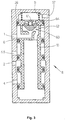
- the trailer brake valve (8) is in Fig. 2 in both Switching states, in Fig. 2a in the basic valve position and shown in Fig. 2b in the valve tear-off position. in the in each case the lower area of the representations of FIG. 2a and Fig. 2b are the switching states of the valve as Pneumatic circuit diagrams of a piston operated 3/2-way valve shown; the upper area shows these switching states in the implementation of the trailer brake valve (8) as a slide valve.
- the pneumatic circuit diagram shows that the basic valve position of the pistons (7), the is designed as an actuating piston for the valve, in its unactuated state, so that in the trailer brake valve (8) the compounds discussed above G2) and G1) [in the event that the supply pressure at port (1) is present, the check valve explained below (6) operated in the forward direction] are.
- the trailer brake valve (8) as a slide valve corresponding to each 2a or 2b is the upper region with an actuating piston provided with an O-ring seal (16) (7) with the valve slide (10) firmly and pressure-tight connected.
- the actuating piston (7) has a first (17) and a second (18) active surface.
- the first effective area (17) is through the cross-sectional area of the actuating piston (7) is formed and the second active surface (18) due to the structural union of actuating pistons (7) and valve slide (10) configured as an annular surface, where the inner ring diameter by the outer diameter the valve slide seals (14) is.
- the first active surface (17) is larger than the second ring active surface (18).
- the check valve (6) is in the direction of action shown installed in the actuating piston (7), both Active surfaces (18) and (17) through this check valve are interconnected such that the direction of passage the check valve (6) from the second one (18) to the first (17) active surface. Because the second Effective surface (18) from the supply connection (1) Pressure and the first effective area (17) of the Pressure applied to the container connection (3) the check valve (6) is always in the forward direction switched when the at the supply connection (1) The pressure applied is greater than that at the tank connection (3) applied pressure.
- the actuating piston valve slide arrangement is located (7, 10) by the Effect of the return spring (11) on the first stop (26) of the valve housing.
- the connections G1) and G2) explained above.
- G1 and G2 each make direct connections represents, d. H. are in the pneumatic paths no mechanical links inserted [the Compound G2 corresponds in DE 28 10 850 A1 that the pressure at the local control connection (7) initially on the relay piston there (6) as mechanical Acts pontic].
- the check valve (6) is in the reverse direction, which causes the connection A1) explained above.
- the valve spool (10) is a pressure channel (13) in the form of a Hole provided.
- the connection A2 explained above) is through the pneumatic connection from the container connection (3) via the blind hole pressure channel (12) and the Pressure channel (13) for brake pressure connection (2).
- the check valve (6) can also be designed by using the O-ring (16) as a grooved ring in a suitable manner Installation direction is formed, or by another Place a check valve is provided which connects the two pressure rooms, the one force exert on the active surface.
- valve slide (10) suitable slide valve seal (14) as the first slide seal and to seal against that Brake pressure connection (2) [this seal is for the case the basic valve position is important] on the valve slide (10) a slide valve seal (15) as a second slide seal intended.
- the actuating piston can be used to simplify production (7) also integrally connected to the valve slide (10) be so that the actuating piston valve spool unit (7, 10) e.g. B. completely as a turned part or Injection molded plastic part can be produced.
- the starting point for loosening is the condition of the trailer brake valve (8) in its demolition position Fig. 2b, in which the brake pressure connection (2) directly with the container connection (3) is connected and the brake cylinder by applying the pressure in the reservoir pressure container (9) prevailing pressure braked are. As long as this emergency braking in the reservoir pressure container (9) there is still sufficient pressure the trailer cannot be moved.
- the release valve (33) 1 the release lever (25) actuated; corresponding Fig. 2a is the air from the supply pressure container (9) via the container connection (3) on the release connection (5) and is then, as shown in Fig. 1, over the effective for the actuated state of the release valve (33) Pressure channel (24) fed into the supply connection (1).
- the pressure prevailing in the reservoir pressure container acts now on both active surfaces (17) and (18) according to Fig. 2a on.
- the return spring (11) is dimensioned in such a way that it is the force by the area share by which the second active surface (18) compared to the first Active area (17) is reduced, canceled and overcompensated in such a way, that the actuating piston valve spool arrangement (7, 10) from the return spring (11) to the first stop (26) is pushed.
- the pressure chambers connected to the brake pressure connection (2) d. H. the brake cylinder is vented so that the brake is solved.
- Trailer brake valve (8) may also open a trailer without electronic brake control can be used; these are conventionally braked Followers, whose good timing allows it to an airflow gain in the trailer brake valve dispense.
- FIG. 4 is the inventive one Trailer brake valve in one embodiment shown as a slide valve, in which the Slider actuation only from the supply connection (1) depends on the applied pressure, i. H. in which the pressure at the container connection (3) is none Exerts force on the valve spool (10).
- This is the trailer brake valve (8) as a pressure-relieved valve built, in which on the valve spool (10) of none other connection, except the supply connection (1), which has an effective area explained below acts on this force, generates a pressure force becomes.
- FIGS. 3 and 4 Pneumatic circuit diagrams as in the lower parts 2a and 2b are omitted because the pneumatic circuit diagrams belonging to FIGS. 3 and 4 are basically the same; it exists only the difference that, as explained, the valve spool (10) according to FIGS. 3 and 4 not on the pressure difference between the supply connection (1) and the container connection (3) actuated, but exclusively due to the pressure at the supply connection (1) is switched.
- valve spool (10) is as mentioned, designed as a valve spool piston, d. H. it combines the functions of the above Valve spool (10) and the actuating piston (7).
- the valve spool (10) is with the return spring (11) loaded and has two positions; one in FIG. 3 shown basic position, in which the valve spool (10) abuts the first stop (26), and one in
- Fig. 4 shows the demolition position, in which the valve slide (10) comes to rest on the second stop (27).
- the check valve (6) explained above is in Fig. 3, Fig. 4 realized as a grooved ring.
- the compounds (G1) explained above [pneumatic connection supply connection (1) with Container connection (3)] and (G2) [pneumatic connection Brake pressure connection (2) with brake specification connection (4)] realized. 4 are in the position shown of the valve spool (10) the compounds (A1) explained above [pneumatic termination supply connection (1)] and (A2) [pneumatic connection brake pressure connection (2) realized with container connection (3)].
- a pilot valve (60) is integrated in the valve slide (10), which consists of a valve switching element (62), one spring acting on the valve switching element (62) (61), a first valve seat (63) and a second Valve seat (64) exists.
- the pilot valve points according to its two valve seats (60) two positions, one starting position and a switch position on.
- the starting position of the pilot valve (60) is shown in Fig. 4: In the There is no pressure at the supply connection when the demolition position (1), and due to the action of the spring (61) Valve switching element (62) on the first valve seat (63), whereby the pressure chamber (67) opposite the supply connection (1) is sealed. Is on a parked Trailer [tear-off position according to Fig. 4] of the supply pressure hose (30) connected, the pressure rises at the supply connection (1), and according to each applied pressure and the effective diameter (65) on the first valve seat (63) becomes a compressive force exerted on the valve switching element (62).
- This effective Diameter (65) determined with the properties the spring (61) [spring length and spring constant] one Pressure threshold, when exceeded the valve switching element (62) from the first valve seat (63).
- the valve switching element (62) is of such a conical shape designed that after lifting off the first valve seat (63) the pressure at the supply connection (1) is now on a larger area acts, causing the pilot valve (60) switches by the pressure force the force of the Spring (61) overcomes and, corresponding to that in Fig. 3rd shown switching position of the pilot valve (60) Valve switching element (62) against the second valve seat (64) presses and closes it.
- the switching hysteresis causes the trailer brake valve not with z. B. a brief shortfall the explained pressure threshold again in the demolition position of FIG. 4 passes.
- the pressure at the supply connection (1) namely be so lowered that the valve switching element (62) by the force of the spring (61) again the first valve seat (63) is pressed. Only the valve spool (10) is driven by the force of the return spring (11) back to the one corresponding to the demolition position pushed back the second stop (27).
- the pressure threshold z. B. expediently placed at 3.5 bar.
- the explained Switching hysteresis can e.g. B. be designed so that the Tear-off position of the trailer brake valve when falling below a pressure of 2.5 bar is resumed.
- the first valve seat (63) acts as a ventilation seat and the second valve seat (64) as a vent seat; in the Bleeding the trailer brake valve (8), d. H. at the Transition of the valve spool (10) when the second one is open Valve seat (64) [Fig. 4] from the first stop (26) to the second stop (27), there is the advantage that the Ventilation takes place directly to the atmosphere and no breathing Spaces exist, as is the case with conventional ones Trailer brake valves is the case. Have breathing spaces the disadvantage that moisture can penetrate the device can, which may lead to icing. Across from conventional trailer brake valves also exist the advantage that the valve switchover takes effect immediately and do not have to travel through a characteristic curve first got to.
- the valve switching element (62) is as Usual seat valve switching element formed in the demolition position [Fig. 7] at the first valve seat (63) and in the basic position [Fig. 6] on the second valve seat (64) is present.
- the function is the same too 3 and 4 with the an exception that after connecting the supply pressure hose (30) the ventilation of the reservoir pressure container (9) via the container connection (3), which via the check valve (6), designed as a grooved ring, only takes place when the 3/2-way valve (70) from its starting position [Fig. 7] in its switch position [Fig. 6] has passed since the pressure of the Supply connection (1) then on the ring nut check valve (6) is also present.
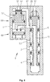
- FIGS. 6, 7 An embodiment modified to FIGS. 6, 7 is available, if the check valve (6) is not a grooved ring in the valve slide (10) realized, but as a separate, in Check valve (6 ') arranged in the housing is. The groove ring (6) is then replaced by a corresponding one O-ring replaced.
- Fig. 6, 7 restriction explained that the ventilation of the reservoir pressure container (9) only after the transition of the 3/2-way valve (70) in its switching position he follows.
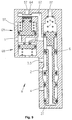
- FIG. 8 and 9 show the Embodiment according to Fig. 6, Fig. 7, in which instead a 3/2-way valve (70) two 2/2-way valves, one first 2/2-way valve (68) as a ventilation valve and a second 2/2-way valve (69) provided as a vent valve are.
- a 3/2-way valve (70) two 2/2-way valves
- a second 2/2-way valve (69) provided as a vent valve are.
- the corresponding one Valve switching element is lifted off the first valve seat (63), so that there is ventilation through the supply connection (1) is done; against it is the second 2/2-way valve (69) closed, the second valve seat (64) closed, so that according to the above Basic position function of the valve slide (10) via Ducking force is pushed to the first stop (26).
Abstract
Description
- Fig. 1
- Das den Funktionsumfang des Anhängerbremsventils erläuternde Blockschaltbild einer Anhänger-EBS-Bremsanlage;
- Fig. 2
- das Anhängerbremsventil in der Ausführung als Schieberventil.
- Fig. 3
- ein als Schieberventil mit einem integrierten Vorsteuerventil ausgebildetes Anhängerbremsventil, bei dem die Ventilbetätigung unabhängig von dem Behälterdruck erfolgt, in der Grundstellung;
- Fig. 4
- das Anhängerbremsventil nach Fig. 3 in der Abrißstellung;
- Fig. 5
- eine Detaildarstellung des Vorsteuerventils in der Grund- (Fig. 5a) und Abrißstellung (Fig. 5b) ;
- Fig. 6
- ein Anhängerbremsventil nach dem Prinzip von Fig. 3, bei dem das Vorsteuerventil als separates 3/2-Wegeventil ausgebildet ist, in der Grundstellung;
- Fig. 7
- das Anhängerbremsventil nach Fig. 6 in der Abrißstellung;
- Fig. 8
- ein Anhängerbremsventil nach dem Prinzip von Fig. 6, bei dem das Vorsteuerventil als eine Kombination von zwei 2/2-Wegeventilen ausgebildet ist, in der Grundstellung;
- Fig.
- 9 das Anhängerbremsventil nach Fig. 8 in der Abrißstellung.
- G1) -
- Der Versorgungsanschluß (1) ist pneumatisch mit dem Behälteranschluß (3) verbunden;
- G2) -
- der Bremsdruckanschluß (2) ist pneumatisch mit dem Bremsvorgabeanschluß (4) verbunden.
- A1) -
- Der Versorgungsanschluß (1) ist pneumatisch abgeschlosssen;
- A2) -
- der Bremsdruckanschluß (2) ist pneumatisch mit dem Behälteranschluß (3) verbunden.
Claims (24)
- Ventileinrichtung für einen an ein Zugfahrzeug angekuppelten Anhänger mit folgenden Merkmalen:gekennzeichnet durch das folgende Merkmal:a) Es ist ein Versorgungsanschluß zur Verbindung mit einem den Vorratsdruck zwischen dem Zugfahrzeug und dem Anhänger übertragenden Druckschlauch vorgesehen;b) es ist ein Bremsvorgabeanschluß zur Verbindung mit einem den Bremsdruck vom Zugfahrzeug zum Anhänger übertragenden Druckschlauch vorgesehen;c) es ist ein Behälteranschluß zur Verbindung mit einem Vorrats-Druckbehälter des Anhängers vorgesehen;d) es ist ein Bremsdruckanschluß zur Ausgabe des Bremsdruckes vorgesehen;e) bei druckbeaufschlagtem Versorgungsanschluß ist der am Bremsdruckanschluß anliegende Druck vom am Bremsvorgabeanschluß anliegenden Druck abhängig;f) bei drucklosem Versorgungsanschluß ist der Bremsdruckanschluß pneumatisch mit dem Behälteranschluß verbunden;g) bei druckbeaufschlagtem Versorgungsanschluß ist der Bremsdruckanschluß pneumatisch direkt mit dem Bremsvorgabeanschluß verbunden.
- Ventileinrichtung nach Anspruch 1, dadurch gekennzeichnet, daß die Ventileinrichtung als Schieberventil ausgestaltet ist.
- Schieberventil nach Anspruch 2, gekennzeichnet durch die folgenden Merkmale:a) Es ist ein Ventilschieber mit einer ersten und einer zweiten Schieber-Dichtung vorgesehen;b) zur Betätigung des Ventilschiebers ist ein Kolben mit einer ersten und mit einer zweiten Wirkfläche vorgesehen.
- Schieberventil nach Anspruch 3, dadurch gekennzeichnet, daß die erste Wirkfläche größer als die zweite Wirkfläche ausgebildet ist.
- Schieberventil nach Anspruch 4, dadurch gekennzeichnet, daß eine die Wirkflächenunterschiede überkompensierende Rückstellfeder vorgesehen ist.
- Schieberventil nach einem der Ansprüche 3 bis 5, gekennzeichnet durch die folgenden Merkmale:a) Der Kolben ist als Betätigungskolben ausgebildet;b) der Betätigungskolben und der Ventilschieber sind baulich vereinigt.
- Schieberventil nach mindestens einem der vorstehenden Ansprüche, gekennzeichnet durch die folgenden Merkmale:a) Die erste Wirkfläche ist durch die Querschnittsfläche des Betätigungskolbens gebildet;b) die zweite Wirkfläche ist durch eine sich aus der baulichen Vereinigung von Betätigungskolben und Ventilschieber ergebenden Ringfläche gebildet;
- Schieberventil nach Anspruch 7, dadurch gekennzeichnet, daß die Druckräume für beide Wirkflächen durch ein Rückschlagventil verbunden sind.
- Schieberventil nach Anspruch 8, dadurch gekennzeichnet, daß für das Rückschlagventil eine von der zweiten zur ersten Wirkfläche verlaufende Durchlaßrichtung vorgesehen ist.
- Schieberventil nach einem der vorstehenden Ansprüche, dadurch gekennzeichnet, daß die Druckleitung zum Bremsdruckanschluß zentral durch die Einheit Betätigungskolben/Ventilschieber geführt ist.
- Schieberventil nach Anspruch 10, gekennzeichnet durch die folgenden Merkmale:a) Die erste Wirkfläche ist pneumatisch mit dem Behälteranschluß verbunden;b) die zweite Wirkfläche ist pneumatisch mit dem Versorgungsanschluß verbunden.
- Schieberventil nach einem der vorstehenden Ansprüche, gekennzeichnet durch die folgenden Merkmale:a) Es ist ein Löseanschluß vorgesehen;b) der Löseanschluß ist pneumatisch mit dem Druckraum der ersten Wirkfläche verbunden.
- Schieberventil nach Anspruch 2, gekennzeichnet durch die folgenden Merkmale:a) Das Schieberventil weist einen mit einer Rückstellfeder belasteten Ventilschieber mit zwei Stellungen, einer Grundstellung und einer Abrißstellung, auf;b) die Grundstellung ist bei druckbeaufschlagtem Versorgungsanschluß durch eine auf den Ventilschieber über eine Wirkfläche einwirkende Druckkraft eingenommen;c) die Abrißstellung ist bei drucklosem Versorgungsanschluß durch die Wirkung der Rückstellfeder eingenommen.
- Schieberventil nach Anspruch 13, gekennzeichnet durch die folgenden Merkmale:a) Es ist ein mit dem Druck des Versorgungsanschlusses beaufschlagtes Vorsteuerventil mit zwei Stellungen, einer Ausgangsstellung und einer Schaltstellung, vorgesehen;b) die auf den Ventilschieber einwirkende Druckkraft ist von der Stellung des Vorsteuerventils abhängig.
- Schieberventil nach Anspruch 14, gekennzeichnet durch die folgenden Merkmale:a) Bei Unterschreiten einer festlegbaren Druckschwelle durch den am Versorgungsanschluß anliegenden Druck ist am Vorsteuerventil durch die Wirkung einer Feder die Ausgangsstellung eingenommen;b) bei Erreichen oder Überschreiten der festlegbaren Druckschwelle durch den am Versorgungsanschluß anliegenden Druck ist am Vorsteuerventil die Schaltstellung eingenommen.
- Schieberventil nach Anspruch 15, dadurch gekennzeichnet, daß in der Schaltstellung des Vorsteuerventils die auf den Ventilschieber einwirkende Druckkraft vergrößert ist.
- Schieberventil nach Anspruch 16, dadurch gekennzeichnet, daß die Vergrößerung der auf den Ventilschieber einwirkenden Druckkraft durch eine Drukkerhöhung realisiert ist.
- Schieberventil nach Anspruch 16, dadurch gekennzeichnet, daß das Vorsteuerventil im Ventilschieber integriert ist.
- Schieberventil nach Anspruch 18, gekennzeichnet durch die folgenden Merkmale:a) In der Ausgangsstellung des Vorsteuerventils ist durch die Wirkung der Feder eine dichtende Verbindung eines Ventilschaltgliedes mit einem ersten Ventilsitz hergestellt;b) in der Schaltstellung des Vorsteuerventils ist eine dichtende Verbindung des Ventilschaltgliedes mit einem zweiten Ventilsitz hergestellt.
- Schieberventil nach Anspruch 19, dadurch gekennzeichnet, daß die Höhe der festlegbaren Druckschwelle zur Einnahme der Schaltstellung des Vorsteuerventils durch die Eigenschaften der auf das Ventilschaltglied einwirkenden Feder und durch den wirksamen Durchmesser des ersten Ventilsitzes bestimmt sind.
- Schieberventil nach Anspruch 20, dadurch gekennzeichnet, daß daß zur Bildung einer Schalthysterese für die festlegbare Druckschwelle der wirksame Durchmesser des zweiten Ventilsitzes größer als der wirksame Durchmesser des ersten Ventilsitzes gewählt ist.
- Schieberventil nach Anspruch 17, dadurch gekennzeichnet, daß das Vorsteuerventil in einem separat zum Gehäuseteil des Ventilschiebers angebrachten Gehäuseteil angeordnet ist.
- Schieberventil nach Anspruch 22, dadurch gekennzeichnet, daß das Vorsteuerventil als 3/2-Wege-Ventil realisiert ist.
- Schieberventil nach Anspruch 23, dadurch gekennzeichnet, daß das Vorsteuerventil als eine Kombination von zwei 2/2-Wege-Ventilen realisiert ist.
Applications Claiming Priority (4)
| Application Number | Priority Date | Filing Date | Title |
|---|---|---|---|
| DE10045415 | 2000-09-14 | ||
| DE10045415 | 2000-09-14 | ||
| DE10139748A DE10139748A1 (de) | 2000-09-14 | 2001-08-13 | Anhängerbremsventil für einen Anhänger mit elektronischer Bremsregelung |
| DE10139748 | 2001-08-13 |
Publications (3)
| Publication Number | Publication Date |
|---|---|
| EP1188635A2 true EP1188635A2 (de) | 2002-03-20 |
| EP1188635A3 EP1188635A3 (de) | 2002-12-04 |
| EP1188635B1 EP1188635B1 (de) | 2007-05-02 |
Family
ID=26007048
Family Applications (1)
| Application Number | Title | Priority Date | Filing Date |
|---|---|---|---|
| EP20010120605 Expired - Lifetime EP1188635B1 (de) | 2000-09-14 | 2001-08-29 | Anhängerbremsventil für einen Anhänger mit elektronischer Bremsregelung |
Country Status (3)
| Country | Link |
|---|---|
| EP (1) | EP1188635B1 (de) |
| DE (1) | DE50112427D1 (de) |
| ES (1) | ES2283361T3 (de) |
Cited By (1)
| Publication number | Priority date | Publication date | Assignee | Title |
|---|---|---|---|---|
| EP2757010A1 (de) * | 2013-01-18 | 2014-07-23 | Haldex Brake Products GmbH | Ventileinrichtung für eine Druckluftanlage eines Anhängers eines Nutzfahrzeugs |
Families Citing this family (1)
| Publication number | Priority date | Publication date | Assignee | Title |
|---|---|---|---|---|
| DE102012101871B4 (de) | 2012-03-06 | 2013-12-12 | Haldex Brake Products Gmbh | Parkbremsventileinrichtung und pneumatische Anhänger-Druckluftbremsanlage |
Citations (4)
| Publication number | Priority date | Publication date | Assignee | Title |
|---|---|---|---|---|
| DE2810850A1 (de) | 1978-03-13 | 1979-10-18 | Wabco Fahrzeugbremsen Gmbh | Anhaenger-bremsventil |
| DE3031105A1 (de) | 1980-08-16 | 1982-04-22 | Wabco Fahrzeugbremsen Gmbh, 3000 Hannover | Lastabhaengig geregelte zweileitungs-anhaengerbremsanlage |
| DE3207793C2 (de) | 1982-03-04 | 1992-09-17 | Robert Bosch Gmbh, 7000 Stuttgart, De | |
| EP0586203B1 (de) | 1992-09-03 | 1997-01-02 | Grau Limited | Bremsanlagen |
Family Cites Families (4)
| Publication number | Priority date | Publication date | Assignee | Title |
|---|---|---|---|---|
| US3837361A (en) * | 1971-10-26 | 1974-09-24 | Eaton Corp | Emergency control valve |
| US4002374A (en) * | 1975-05-07 | 1977-01-11 | Sloan Valve Company | Trailer air distribution valve |
| US4080004A (en) * | 1976-04-15 | 1978-03-21 | Wagner Electric Corporation | Service and emergency trailer valve |
| DE19818982C2 (de) * | 1998-04-28 | 2001-05-17 | Knorr Bremse Systeme | Park- und Rangierventil für Anhängerfahrzeuge mit einer Federspeicher-Feststellbremse |
-
2001
- 2001-08-29 EP EP20010120605 patent/EP1188635B1/de not_active Expired - Lifetime
- 2001-08-29 ES ES01120605T patent/ES2283361T3/es not_active Expired - Lifetime
- 2001-08-29 DE DE50112427T patent/DE50112427D1/de not_active Expired - Lifetime
Patent Citations (4)
| Publication number | Priority date | Publication date | Assignee | Title |
|---|---|---|---|---|
| DE2810850A1 (de) | 1978-03-13 | 1979-10-18 | Wabco Fahrzeugbremsen Gmbh | Anhaenger-bremsventil |
| DE3031105A1 (de) | 1980-08-16 | 1982-04-22 | Wabco Fahrzeugbremsen Gmbh, 3000 Hannover | Lastabhaengig geregelte zweileitungs-anhaengerbremsanlage |
| DE3207793C2 (de) | 1982-03-04 | 1992-09-17 | Robert Bosch Gmbh, 7000 Stuttgart, De | |
| EP0586203B1 (de) | 1992-09-03 | 1997-01-02 | Grau Limited | Bremsanlagen |
Cited By (1)
| Publication number | Priority date | Publication date | Assignee | Title |
|---|---|---|---|---|
| EP2757010A1 (de) * | 2013-01-18 | 2014-07-23 | Haldex Brake Products GmbH | Ventileinrichtung für eine Druckluftanlage eines Anhängers eines Nutzfahrzeugs |
Also Published As
| Publication number | Publication date |
|---|---|
| DE50112427D1 (de) | 2007-06-14 |
| ES2283361T3 (es) | 2007-11-01 |
| EP1188635B1 (de) | 2007-05-02 |
| EP1188635A3 (de) | 2002-12-04 |
Similar Documents
| Publication | Publication Date | Title |
|---|---|---|
| EP1188634B2 (de) | Anhängerbremsventil für Anhängefahrzeuge mit elektronischer Bremsregelung und erweiterter Sicherheit des geparkten Anhängers | |
| DE102007061908B4 (de) | Parkbremse | |
| EP3678909B1 (de) | Elektropneumatische parkbremssteuereinrichtung und bremsanlage eines fahrzeugs | |
| EP2059429B1 (de) | Ventileinheit für eine elektropneumatische bremssteuerungseinrichtung | |
| EP3129264B1 (de) | Elektropneumatische parkbremssteuereinrichtung | |
| EP2163447B1 (de) | Druckmittelbetätigte Bremsanlage eines Fahrzeugs mit gegenläufige Drücke für Anhängerbremsen erzeugender Feststellbremseinrichtung | |
| EP3600996B1 (de) | Integriertes anhängersteuermodul (tcv) mit externer elektropneumatischer handbremseinheit (eph) | |
| DE102017006356A1 (de) | Elektro-Pneumatische Handbremse (EPH) mit integriertem TCV (Europäische Ansteuerung) | |
| EP2133250B1 (de) | Parkbremsventilanordnung für ein Bremssystem eines Nutzfahrzeuges | |
| DE102016010464A1 (de) | Elektronisch steuerbares pneumatisches Bremssystem in einem Nutzfahrzeug sowie Verfahren zum elektronischen Steuern eines pneumatischen Bremssystems in einem Nutzfahrzeug | |
| DE102007052521A1 (de) | Druckmittelbetätigte Bremseinrichtung eines Zugfahrzeugs mit einem gegenläufige Drücke für Anhängerbremsen erzeugenden Feststellbremsmodul | |
| DE19918070B4 (de) | Druckregelvorrichtung für elektro-pneumatische Bremsanlagen von Fahrzeugen, insbesondere Nutzfahrzeugen | |
| EP3190015A1 (de) | Bremseinrichtung eines zugfahrzeugs und gruppe von bremseinrichtungen | |
| EP3626564B1 (de) | Steuerventil, elektronisch steuerbares bremssystem sowie verfahren zum steuern des elektronisch steuerbaren bremssystems | |
| EP0373315B1 (de) | Anordnung zur Steuerung eines elektrisch gesteuerten Bremskreises einer in einem Fahrzeug angeordneten Mehrkreis-Bremsanlage mit druckmittelbetätigten Bremsen | |
| DE4214547C2 (de) | Fahrzeugbremssystem | |
| EP3626563A1 (de) | Steuerventil, elektronisch steuerbares bremssystem sowie verfahren zum steuern des elektronisch steuerbaren bremssystems | |
| DE102018110088A1 (de) | Steuerventil, elektronisch steuerbares Bremssystem sowie Verfahren zum Steuern des elektronisch steuerbaren Bremssystems | |
| EP0378810B1 (de) | Druckluftbremseinrichtung für Kraftfahrzeuge | |
| DE20122549U1 (de) | Anhängerbremsventil für Anhängefahrzeuge mit elektronischer Bremsregelung und erweiterter Sicherheit des geparkten Anhängers | |
| DE10139748A1 (de) | Anhängerbremsventil für einen Anhänger mit elektronischer Bremsregelung | |
| DE10139757A1 (de) | Anhängerbremsventil für Anhängefahrzeuge mit elektronischer Bremsregelung und erweiterter Sicherheit des geparkten Anhängers | |
| DE19933483C1 (de) | Druckmittelbetätigte Fahrzeugbremsanlage | |
| EP1069016B2 (de) | Druckmittelbetätigte Fahrzeugbremsanlage | |
| DE10042215C5 (de) | Druckmittelbetätigte Fahrzeugbremsanlage mit redundanter Ansteuerung wenigstens eines Bremszylinders |
Legal Events
| Date | Code | Title | Description |
|---|---|---|---|
| PUAI | Public reference made under article 153(3) epc to a published international application that has entered the european phase |
Free format text: ORIGINAL CODE: 0009012 |
|
| AK | Designated contracting states |
Kind code of ref document: A2 Designated state(s): AT BE CH CY DE DK ES FI FR GB GR IE IT LI LU MC NL PT SE TR |
|
| AX | Request for extension of the european patent |
Free format text: AL;LT;LV;MK;RO;SI |
|
| PUAL | Search report despatched |
Free format text: ORIGINAL CODE: 0009013 |
|
| AK | Designated contracting states |
Kind code of ref document: A3 Designated state(s): AT BE CH CY DE DK ES FI FR GB GR IE IT LI LU MC NL PT SE TR |
|
| AX | Request for extension of the european patent |
Free format text: AL;LT;LV;MK;RO;SI |
|
| RIC1 | Information provided on ipc code assigned before grant |
Free format text: 7B 60T 17/18 A, 7B 60T 15/20 B, 7B 60T 13/68 B, 7B 60T 13/66 B, 7B 60T 13/26 B, 7B 60T 8/32 B, 7B 60T 8/18 B, 7B 60T 15/24 B |
|
| 17P | Request for examination filed |
Effective date: 20030604 |
|
| AKX | Designation fees paid |
Designated state(s): DE ES FR GB IT SE |
|
| GRAP | Despatch of communication of intention to grant a patent |
Free format text: ORIGINAL CODE: EPIDOSNIGR1 |
|
| RAP1 | Party data changed (applicant data changed or rights of an application transferred) |
Owner name: WABCO GMBH |
|
| GRAS | Grant fee paid |
Free format text: ORIGINAL CODE: EPIDOSNIGR3 |
|
| GRAA | (expected) grant |
Free format text: ORIGINAL CODE: 0009210 |
|
| AK | Designated contracting states |
Kind code of ref document: B1 Designated state(s): DE ES FR GB IT SE |
|
| REG | Reference to a national code |
Ref country code: GB Ref legal event code: FG4D Free format text: NOT ENGLISH |
|
| RIN1 | Information on inventor provided before grant (corrected) |
Inventor name: WOLFF, HANS-KLAUS Inventor name: WITTE, NORBERT Inventor name: STENDER, AXEL Inventor name: SIEKER, ARMIN Inventor name: REINEFELD, WILFRIED Inventor name: LINDEMANN, KLAUS Inventor name: KOCH, JUERGEN Inventor name: FRANK, DIETER |
|
| REF | Corresponds to: |
Ref document number: 50112427 Country of ref document: DE Date of ref document: 20070614 Kind code of ref document: P |
|
| REG | Reference to a national code |
Ref country code: SE Ref legal event code: TRGR |
|
| GBT | Gb: translation of ep patent filed (gb section 77(6)(a)/1977) |
Effective date: 20070717 |
|
| ET | Fr: translation filed | ||
| REG | Reference to a national code |
Ref country code: ES Ref legal event code: FG2A Ref document number: 2283361 Country of ref document: ES Kind code of ref document: T3 |
|
| PLBE | No opposition filed within time limit |
Free format text: ORIGINAL CODE: 0009261 |
|
| STAA | Information on the status of an ep patent application or granted ep patent |
Free format text: STATUS: NO OPPOSITION FILED WITHIN TIME LIMIT |
|
| 26N | No opposition filed |
Effective date: 20080205 |
|
| REG | Reference to a national code |
Ref country code: FR Ref legal event code: PLFP Year of fee payment: 16 |
|
| REG | Reference to a national code |
Ref country code: FR Ref legal event code: PLFP Year of fee payment: 17 |
|
| REG | Reference to a national code |
Ref country code: FR Ref legal event code: PLFP Year of fee payment: 18 |
|
| PGFP | Annual fee paid to national office [announced via postgrant information from national office to epo] |
Ref country code: DE Payment date: 20200831 Year of fee payment: 20 Ref country code: FR Payment date: 20200820 Year of fee payment: 20 Ref country code: GB Payment date: 20200825 Year of fee payment: 20 Ref country code: ES Payment date: 20200917 Year of fee payment: 20 |
|
| PGFP | Annual fee paid to national office [announced via postgrant information from national office to epo] |
Ref country code: SE Payment date: 20200825 Year of fee payment: 20 Ref country code: IT Payment date: 20200831 Year of fee payment: 20 |
|
| REG | Reference to a national code |
Ref country code: DE Ref legal event code: R081 Ref document number: 50112427 Country of ref document: DE Owner name: ZF CV SYSTEMS HANNOVER GMBH, DE Free format text: FORMER OWNER: WABCO GMBH, 30453 HANNOVER, DE |
|
| REG | Reference to a national code |
Ref country code: DE Ref legal event code: R071 Ref document number: 50112427 Country of ref document: DE |
|
| REG | Reference to a national code |
Ref country code: GB Ref legal event code: PE20 Expiry date: 20210828 |
|
| REG | Reference to a national code |
Ref country code: SE Ref legal event code: EUG |
|
| PG25 | Lapsed in a contracting state [announced via postgrant information from national office to epo] |
Ref country code: GB Free format text: LAPSE BECAUSE OF EXPIRATION OF PROTECTION Effective date: 20210828 |
|
| REG | Reference to a national code |
Ref country code: ES Ref legal event code: FD2A Effective date: 20211207 |
|
| PG25 | Lapsed in a contracting state [announced via postgrant information from national office to epo] |
Ref country code: ES Free format text: LAPSE BECAUSE OF EXPIRATION OF PROTECTION Effective date: 20210830 |