EP3677726A1 - Radlader - Google Patents
Radlader Download PDFInfo
- Publication number
- EP3677726A1 EP3677726A1 EP19216002.6A EP19216002A EP3677726A1 EP 3677726 A1 EP3677726 A1 EP 3677726A1 EP 19216002 A EP19216002 A EP 19216002A EP 3677726 A1 EP3677726 A1 EP 3677726A1
- Authority
- EP
- European Patent Office
- Prior art keywords
- arm
- cylinder
- wheel loader
- lifting frame
- articulated
- Prior art date
- Legal status (The legal status is an assumption and is not a legal conclusion. Google has not performed a legal analysis and makes no representation as to the accuracy of the status listed.)
- Granted
Links
Images


Classifications
-
- E—FIXED CONSTRUCTIONS
- E02—HYDRAULIC ENGINEERING; FOUNDATIONS; SOIL SHIFTING
- E02F—DREDGING; SOIL-SHIFTING
- E02F3/00—Dredgers; Soil-shifting machines
- E02F3/04—Dredgers; Soil-shifting machines mechanically-driven
- E02F3/28—Dredgers; Soil-shifting machines mechanically-driven with digging tools mounted on a dipper- or bucket-arm, i.e. there is either one arm or a pair of arms, e.g. dippers, buckets
- E02F3/34—Dredgers; Soil-shifting machines mechanically-driven with digging tools mounted on a dipper- or bucket-arm, i.e. there is either one arm or a pair of arms, e.g. dippers, buckets with bucket-arms, i.e. a pair of arms, e.g. manufacturing processes, form, geometry, material of bucket-arms directly pivoted on the frames of tractors or self-propelled machines
- E02F3/3405—Dredgers; Soil-shifting machines mechanically-driven with digging tools mounted on a dipper- or bucket-arm, i.e. there is either one arm or a pair of arms, e.g. dippers, buckets with bucket-arms, i.e. a pair of arms, e.g. manufacturing processes, form, geometry, material of bucket-arms directly pivoted on the frames of tractors or self-propelled machines and comprising an additional linkage mechanism
-
- B—PERFORMING OPERATIONS; TRANSPORTING
- B66—HOISTING; LIFTING; HAULING
- B66F—HOISTING, LIFTING, HAULING OR PUSHING, NOT OTHERWISE PROVIDED FOR, e.g. DEVICES WHICH APPLY A LIFTING OR PUSHING FORCE DIRECTLY TO THE SURFACE OF A LOAD
- B66F9/00—Devices for lifting or lowering bulky or heavy goods for loading or unloading purposes
- B66F9/06—Devices for lifting or lowering bulky or heavy goods for loading or unloading purposes movable, with their loads, on wheels or the like, e.g. fork-lift trucks
- B66F9/065—Devices for lifting or lowering bulky or heavy goods for loading or unloading purposes movable, with their loads, on wheels or the like, e.g. fork-lift trucks non-masted
-
- B—PERFORMING OPERATIONS; TRANSPORTING
- B66—HOISTING; LIFTING; HAULING
- B66F—HOISTING, LIFTING, HAULING OR PUSHING, NOT OTHERWISE PROVIDED FOR, e.g. DEVICES WHICH APPLY A LIFTING OR PUSHING FORCE DIRECTLY TO THE SURFACE OF A LOAD
- B66F9/00—Devices for lifting or lowering bulky or heavy goods for loading or unloading purposes
- B66F9/06—Devices for lifting or lowering bulky or heavy goods for loading or unloading purposes movable, with their loads, on wheels or the like, e.g. fork-lift trucks
- B66F9/075—Constructional features or details
- B66F9/20—Means for actuating or controlling masts, platforms, or forks
- B66F9/22—Hydraulic devices or systems
-
- E—FIXED CONSTRUCTIONS
- E02—HYDRAULIC ENGINEERING; FOUNDATIONS; SOIL SHIFTING
- E02F—DREDGING; SOIL-SHIFTING
- E02F3/00—Dredgers; Soil-shifting machines
- E02F3/04—Dredgers; Soil-shifting machines mechanically-driven
- E02F3/28—Dredgers; Soil-shifting machines mechanically-driven with digging tools mounted on a dipper- or bucket-arm, i.e. there is either one arm or a pair of arms, e.g. dippers, buckets
- E02F3/34—Dredgers; Soil-shifting machines mechanically-driven with digging tools mounted on a dipper- or bucket-arm, i.e. there is either one arm or a pair of arms, e.g. dippers, buckets with bucket-arms, i.e. a pair of arms, e.g. manufacturing processes, form, geometry, material of bucket-arms directly pivoted on the frames of tractors or self-propelled machines
- E02F3/358—Bucket-arms pivoted on a turntable being part of a tractor frame or buckets arranged on a turntable supported by the arms
Definitions
- the invention relates to a wheel loader with a lifting frame extending in one working direction, an attachment arranged at the free end of the lifting frame and a lifting cylinder articulated at one end to the lifting frame.
- Such wheel loaders are generally known and basically have two functions with respect to the attachment, namely lifting / lowering and tipping, which are carried out by appropriately provided working cylinders, which are generally designed as hydraulic cylinders.
- the aforementioned movements are carried out regularly by an operating lever which carries out the lifting / lowering in the longitudinal direction of the vehicle and the tilting in and out transversely thereto.
- the wheel loader is designed as a swivel loader, there is also the possibility of pivoting the attachment by 90 ° to the left or right.
- the lifting frame is attached to a swivel swivel chair.
- the swiveling is carried out either by a foot pedal transversely to the direction of travel or an operating lever that can be rotated about the vertical axis.
- Typical attachments used in wheel loaders are, for example, forks or shovels for transporting piece goods and bulk goods.
- the object of the invention is therefore to provide a wheel loader that can take up and unload general cargo and bulk goods without the wheel loader being located directly at the place where the goods to be picked up or unloaded are to be picked up or unloaded.
- the basic idea of the invention is to design a wheel loader with offset kinematics, in particular in the form of a parallelogram, which enables the lifting frame and thus the attachment to move essentially horizontally in the working direction without the vehicle having to move in the working direction.
- the working direction corresponds to the longitudinal axis of the vehicle when the bucket assembly is aligned or the level of the longitudinal axis of the lifting frame when the swivel chair is pivoted. This makes it possible for the vehicle to be arranged at a distance from the unloading or receiving location of the piece or bulk goods and for the piece or bulk goods to be picked up or unloaded, even if an obstacle prevents the wheel loader from moving directly to the place.
- a wheel loader is therefore proposed with a lifting frame extending in one working direction, an attachment arranged at the free end of the lifting frame and a lifting cylinder which is articulated, in particular, approximately in the center and is connected at one end to the lifting frame in an articulated manner.
- a head plate is provided with a first arm articulated to the head plate, the free end of which is connected to a working cylinder articulated to the head plate (hereinafter referred to as an offset cylinder), the end of the lifting frame opposite the implement being articulated to the free end of the is connected to the first arm, and the lifting cylinder is articulated at its other end to an actuator which is articulated on the one hand to the free end of the first arm and on the other hand to the free end of a second arm articulated to the head plate.
- an offset cylinder articulated to an actuator which is articulated on the one hand to the free end of the first arm and on the other hand to the free end of a second arm articulated to the head plate.
- the lifting frame, the first arm and the offset cylinder preferably form a common joint with a common axis of rotation. This configuration enables a particularly stable and space-saving construction of the wheel loader designed according to the invention.
- the actuator is preferably triangular, the first arm, the second arm and the lifting cylinder each being articulated to the actuator in the region of a corner.
- the axis of the joint connecting the head plate to the first arm and the axis of the joint connecting the head plate to the second arm are further preferably arranged in a plane parallel to the horizontal or parallel to the plane of the head plate.
- first arm and the second arm are arranged parallel to one another, so that, together with the actuator and the head plate, there is an offset kinematics designed as a parallelogram.
- the head plate is rotatably mounted.
- the wheel loader cannot move laterally on a shelf, since the wheels cannot be steered to the side by 90 °.
- the rotatable offset kinematics make it possible to remove a pallet from a shelf set up parallel to the direction of travel.
- the lifting cylinder and / or the offset cylinder is designed as a hydraulic cylinder.
- the piston chamber of the lifting cylinder is communicatively connected to the piston chamber of the offset cylinder and the rod chamber of the lifting cylinder is connected to the rod chamber of the offset cylinder. Since the Offset cylinder pulls the lifting frame in the working direction (and does not press), the oil displaced by the lifting cylinder (during the lifting process) can be used to initiate the pulling motion of the offset kinematics.
- This preferred embodiment makes it possible to simultaneously control the lifting cylinder and the offset cylinder and to design simple operation for the driver of the wheel loader.
- the offset cylinder when shortened, is set up to cause an offset of the lifting frame in the working direction.
- a fork or a shovel is preferably considered as an attachment.
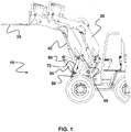
- Fig. 1 shows a schematic side view of a particularly preferred wheel loader of the invention.
- FIG. 1 a wheel loader 10 with a lifting frame 20 extending in a working direction, at the free end of which an attachment 30 in the form of a fork is arranged.
- the lifting frame 20 is articulated to a lifting cylinder 40 so that the lifting frame 20 and thus the attachment 30 can be raised and lowered.
- the wheel loader 10 has a rotatably mounted head plate 50 with a first arm 60 hinged to the head plate 50, the free end of which is connected to an offset cylinder 70 hinged to the head plate 50.
- the end of the lifting frame 20 opposite the attachment 30 is connected in an articulated manner to the free end of the first arm 60, and the lifting cylinder 40 is connected in an articulated manner to an actuator 80 at its other end.
- the actuator is in turn articulated on the one hand to the free end of the first arm 60 and on the other hand to the free end of a second arm 90 articulated to the head plate 50, so that a change in length of the offset cylinder 70 causes an offset of the lifting frame 20 in the plane of the working direction of the Attachment 30 causes.
- the offset cylinder 70 when shortened, causes the lifting frame 20 to be displaced forward in the working direction.
- Fig. 2 shows a front view of a particularly preferred wheel loader with a laterally pivoted lifting frame in a raised first position (A) and in a lowered second position (B).
- A raised first position
- B lowered second position
- Fig. 2 It can be seen that if you control all hydraulic cylinders electronically, a pallet can be transported vertically upwards, as is otherwise only possible with a forklift, because the forward movement of the attachment (due to the circular arc that the lifting frame 20 describes when lifting) is over the folding mechanism of the offset kinematics is compensated.
- FIG. 3 shows a detailed view of the components forming the displacement kinematics in a first position (A) and in a second position (B) displacing the lifting frame 20 in the working direction.
- the double displacement cylinder 70 moves the mechanism more or less horizontally, the parallelogram being designed so that vertical movement is minimal.
Landscapes
- Engineering & Computer Science (AREA)
- Structural Engineering (AREA)
- Mechanical Engineering (AREA)
- Civil Engineering (AREA)
- Transportation (AREA)
- Life Sciences & Earth Sciences (AREA)
- General Engineering & Computer Science (AREA)
- Mining & Mineral Resources (AREA)
- Geology (AREA)
- Chemical & Material Sciences (AREA)
- Combustion & Propulsion (AREA)
- Shovels (AREA)
- Casting Devices For Molds (AREA)
Abstract
Description
- Die Erfindung betrifft einen Radlader mit einem sich in einer Arbeitsrichtung erstreckenden Hubrahmen, einem am freien Ende des Hubrahmens angeordneten Anbaugerät und einem mit seinem einen Ende gelenkig mit dem Hubrahmen verbundenen Hubzylinder.
- Derartige Radlader sind gemeinhin bekannt und weisen in Bezug auf das Anbaugerät grundsätzlich zwei Funktionen auf, nämlich Heben/Senken und Kippen, die durch entsprechend vorgesehene, in der Regel als Hydraulikzylinder ausgebildete Arbeitszylinder ausgeführt werden. Die vorgenannten Bewegungen werden regelmäßig durch einen Bedienhebel ausgeführt, der in Längsrichtung des Fahrzeugs das Heben/Senken und quer dazu das Ein- und Auskippen durchführt.
- Ist der Radlader als Schwenklader ausgebildet besteht außerdem die Möglichkeit, das Anbaugerät um je 90° nach links oder rechts zu verschwenken. Dazu ist der Hubrahmen an einem schwenkbaren Drehstuhl angebracht. Das Schwenken wird dabei entweder durch ein Fußpedal quer zur Fahrtrichtung oder einen, um die Hochachse verdrehbaren Bedienhebel ausgeführt.
- Typische bei Radladern verwendete Anbaugeräte sind beispielsweise Gabeln oder Schaufeln zum Transportieren von Stückgut und Schüttgut.
- Wenngleich derartige Radlader grundsätzlich vorteilhaft ausgebildet sind, besteht das Problem, dass die bekannten Radlader sehr dicht an denjenigen Ort herangefahren werden müssen, an dem das Stückgut oder Schüttgut abgeladen oder aufgenommen werden soll. Dieses Problem besteht insbesondere im Baustellenbereich mit durch Hindernisse unzugänglichen Bereichen.
- Aufgabe der Erfindung ist es daher, einen Radlader zu schaffen, der Stückgut und Schüttgut aufnehmen und abladen kann, ohne dass sich der Radlader unmittelbar an dem Ort befindet, an dem das aufzunehmende oder abzuladende Gut aufgenommen oder abgeladen werden soll.
- Diese Aufgabe wird erfindungsgemäß durch den Radlader mit den Merkmalen von Anspruch 1 gelöst. Die Unteransprüche geben vorteilhafte Ausgestaltungen der Erfindung wieder.
- Grundgedanke der Erfindung ist es, einen Radlader mit einer insbesondere als Parallelogramm ausgebildeten Versatzkinematik auszugestalten, die eine im Wesentlichen horizontale Bewegung des Hubrahmens und damit des Anbaugeräts in Arbeitsrichtung ermöglicht, ohne dass sich das Fahrzeug in Arbeitsrichtung bewegen muss. Die Arbeitsrichtung entspricht der Fahrzeuglängsachse bei gerade ausgerichtetem Schaufelaggregat bzw. der Ebene der Längsachse des Hubrahmens bei verschwenktem Drehstuhl. Dadurch ist es ermöglicht, dass das Fahrzeug vom Ablade- oder Aufnahmeort des Stück- oder Schüttguts beabstandet angeordnet und das Stück- oder Schüttgut aufgenommen oder abgeladen werden kann, selbst wenn ein Hindernis das unmittelbare Heranfahren des Radladers an den Ort verhindert.
- Es wird also ein Radlader vorgeschlagen mit einem sich in einer Arbeitsrichtung erstreckenden Hubrahmen, einem am freien Ende des Hubrahmens angeordneten Anbaugerät und einem insbesondere in etwa mittig angelenkten, mit seinem einen Ende gelenkig mit dem Hubrahmen verbundenen Hubzylinder. Erfindungsgemäß ist eine Kopfplatte vorgesehen mit einem an der Kopfplatte gelenkig befestigten ersten Arm, dessen freies Ende mit einem an der Kopfplatte gelenkig befestigten Arbeitszylinder (im Folgenden: Versatzzylinder genannt) verbunden ist, wobei das dem Anbaugerät gegenüberliegende Ende des Hubrahmens gelenkig mit dem freien Ende des ersten Arms verbunden ist, und der Hubzylinder mit seinem anderen Ende mit einem Stellglied gelenkig verbunden ist, das einerseits gelenkig mit dem freien Ende des ersten Arms und andererseits mit dem freien Ende eines gelenkig mit der Kopfplatte verbundenen zweiten Arms gelenkig verbunden ist. Durch diese Ausgestaltung bewirkt eine Längenänderung des Versatzzylinders einen Versatz des Hubrahmens in der Ebene der Arbeitsrichtung.
- Erfindungsgemäß ist also es möglich, ein Anbaugerät weiter in Arbeitsrichtung zu bewegen, wenn sich das Fahrzeug aufgrund eines Hindernisses nicht mehr weiterbewegen lässt. So eine Bewegung lässt sich zwar grundsätzlich auch mit einem Teleskop bewerkstelligen - die Bewegungsrichtung ist aber stark von dem Winkel, in dem sich das Teleskop bezüglich des Erdbodens befindet, abhängig. Im Falle eines Hochregals, würde sich das Teleskop in einem 45° bis 80° Winkel nach oben gerichtet befinden und somit würde die Teleskopbewegung nicht waagerecht erfolgen, sondern schräg nach oben. Dieser Nachteil tritt bei der erfindungsgemäßen Ausgestaltung nicht auf.
- Bevorzugt bilden der Hubrahmen, der erste Arm und der Versatzzylinder ein gemeinsames Gelenk mit einer gemeinsamen Drehachse aus. Diese Ausgestaltung ermöglicht eine besonders stabile und platzsparende Konstruktion des erfindungsgemäß ausgestalteten Radladers.
- Das Stellglied ist bevorzugt dreieckig ausgebildet, wobei der erste Arm, der zweite Arm und der Hubzylinder jeweils im Bereich einer Ecke des Stellglieds mit diesem gelenkig verbunden sind.
- Die Achse des die Kopfplatte mit dem ersten Arm verbindenden Gelenks und die Achse des die Kopfplatte mit dem zweiten Arm verbindenden Gelenks sind weiter bevorzugt in einer Ebene parallel zur Horizontalen bzw. parallel zur Ebene der Kopfplatte angeordnet.
- Nach einer weiteren bevorzugten Ausgestaltung sind der erste Arm und der zweite Arm parallel zueinander angeordnet, sodass sich gemeinsam mit dem Stellglied und der Kopfplatte eine als Parallelogramm ausgebildete Versatzkinematik ergibt.
- Gemäß einer besonders bevorzugten Ausgestaltung ist die Kopfplatte drehbar gelagert. Im Falle eines 90° verschwenkten Schaufelaggregates kann der Radlader sich seitlich nicht auf ein Regal zu bewegen, da die Räder nicht um 90° zur Seite lenkbar sind. Mit der drehbar gelagerten Versatzkinematik ergibt sich in so einer Situation die Möglichkeit, eine Palette aus einem parallel zur Fahrtrichtung aufgestellten Regal zu entnehmen.
- Insbesondere ist der Hubzylinder und/oder der Versatzzylinder als Hydraulikzylinder ausgebildet. Speziell ist bei einer Ausbildung des Hubzylinders und des Versatzzylinders als Hydraulikzylinder vorgesehen, dass der Kolbenraum des Hubzylinders kommunizierend mit dem Kolbenraum des Versatzzylinders und der Stangenraum des Hubzylinders kommunizierend mit dem Stangenraum des Versatzzylinders verbunden ist. Da der Versatzzylinder den Hubrahmen in Arbeitsrichtung zieht (und nicht drückt) kann man das vom Hubzylinder (beim Hebevorgang) verdrängte Öl nutzen, um die Zugbewegung der Versatzkinematik einzuleiten. Dieses erfolgt in der Weise, dass das Hydrauliköl aus der großen Kammer des Hubzylinders in die große Kammer des Versatzzylinders und das Hydrauliköl aus der kleinen Kammer des Hubzylinders in die kleine Kammer des Versatzzylinders verdrängt wird. Durch diese bevorzugte Ausgestaltung ist es möglich, die Ansteuerung des Hub- und des Versatzzylinders gleichzeitig zu realisieren und eine einfache Bedienung für den Fahrer des Radladers zu konstruieren.
- Schließlich ist es vorteilhaft, wenn der Versatzzylinder bei dessen Verkürzung einen Versatz des Hubrahmens in Arbeitsrichtung bewirkend eingerichtet ist.
- Als Anbaugerät kommt bevorzugt eine Gabel oder eine Schaufel in Betracht.
- Die Erfindung wird im Folgenden anhand eines in den beigefügten Zeichnungen dargestellten, besonders bevorzugt ausgestalteten Ausführungsbeispiels näher erläutert. Es zeigen:
- Fig. 1
- eine schematische Seitenansicht eines besonders bevorzugt ausgestalteten Radladers der Erfindung;
- Fig. 2
- eine Frontalansicht eines besonders bevorzugt ausgestalteten Radladers mit einem seitlich verschwenkten Hubrahmen in einer angehobenen ersten Position (A) und in einer abgesenkten zweiten Position (B); und
- Fig. 3
- Detailansicht der die Versatzkinematik bildenden Komponenten in einer ersten Position (A) und in einer den Hubrahmen in die Arbeitsrichtung versetzten zweiten Position (B).
-
Fig. 1 zeigt eine schematische Seitenansicht eines besonders bevorzugt ausgestalteten Radladers der Erfindung. - Insbesondere zeigt
Fig. 1 einen Radlader 10 mit einem sich in einer Arbeitsrichtung erstreckenden Hubrahmen 20, an dessen freiem Ende ein Anbaugerät 30 in Form einer Gabel angeordnet ist. Der Hubrahmen 20 ist gelenkig mit einem Hubzylinder 40 verbunden, sodass der Hubrahmen 20 und damit das Anbaugerät 30 angehoben und abgesenkt werden kann. Der Radlader 10 verfügt über eine drehbar gelagerte Kopfplatte 50 mit einem an der Kopfplatte 50 gelenkig befestigten ersten Arm 60, dessen freies Ende mit einem an der Kopfplatte 50 gelenkig befestigten Versatzzylinder 70 verbunden ist. Dabei ist das dem Anbaugerät 30 gegenüberliegende Ende des Hubrahmens 20 gelenkig mit dem freien Ende des ersten Arms 60 verbunden, und der Hubzylinder 40 mit seinem anderen Ende mit einem Stellglied 80 gelenkig verbunden. Das Stellglied wiederum ist einerseits gelenkig mit dem freien Ende des ersten Arms 60 und andererseits mit dem freien Ende eines gelenkig mit der Kopfplatte 50 verbundenen zweiten Arms 90 gelenkig verbunden, sodass eine Längenänderung des Versatzzylinders 70 einen Versatz des Hubrahmens 20 in der Ebene der Arbeitsrichtung des Anbaugeräts 30 bewirkt. Insbesondere ist zu erkennen, dass der Versatzzylinder 70 bei dessen Verkürzung einen Versatz des Hubrahmens 20 nach vorne in Arbeitsrichtung bewirkt. -
Fig. 2 zeigt eine Frontalansicht eines besonders bevorzugt ausgestalteten Radladers mit einem seitlich verschwenkten Hubrahmen in einer angehobenen ersten Position (A) und in einer abgesenkten zweiten Position (B) gezeigt ist. Insbesondere ist ausFig. 2 ersichtlich, dass man, wenn man alle Hydraulikzylinder elektronisch ansteuert, eine Palette senkrecht nach oben befördern kann, wie es sonst nur mit einem Gabelstapler möglich ist, da die Vorwärtsbewegung des Anbaugerätes (bedingt durch den Kreisbogen, den der Hubrahmen 20 beim Heben beschreibt) über den Klappmechanismus der Versatzkinematik kompensiert wird. - Dieses wird auch aus
Fig. 3 deutlich, die eine Detailansicht der die Versatzkinematik bildenden Komponenten in einer ersten Position (A) und in einer den Hubrahmen 20 in die Arbeitsrichtung versetzenden zweiten Position (B) zeigt. Der doppelt ausgeführte Versatzzylinder 70 bewegt den Mechanismus mehr oder weniger waagerecht, wobei das Parallelogramm so konstruiert ist, dass die vertikale Bewegung minimal ist. - Da die Versatzzylinder 70 den Hubrahmen 20 in Arbeitsrichtung ziehen (und nicht drücken), ist es konstruktiv ermöglicht, das vom Hubzylinder 40 beim Hebevorgang verdrängte Hydrauliköl für die Zugbewegung des Versatzzylinder 70 zu nutzen. Dabei wird das Hydrauliköl aus dem Kolbenraum des Hubzylinders 40 in den Kolbenraum des Versatzzylinders 70 verdrängt und das Hydrauliköl aus dem Stangenraum des Hubzylinders 20 in den Stangenraum des Versatzzylinders 70. Durch diese Ausgestaltung ist ein gleichmäßiger Hebevorgang kombiniert mit einer Vorwärtsbewegung des Hubrahmens 20 bzw. ein gleichmäßiges Absenken kombiniert mit einer Rückwärtsbewegung des Hubrahmens 20 realisiert.
- Schließlich ist in
Fig. 3 zu erkennen, dass sich der erste Arm 60 in der Ausgangsstellung, also in der zurückgezogenen Position des Hubrahmens 20, an einem Anschlag anlehnt, der die Bewegung des Hubrahmens 20 entgegen der Arbeitsrichtung begrenzt.
Claims (10)
- Radlader (10) mit einem sich in einer Arbeitsrichtung erstreckenden Hubrahmen (20), einem am freien Ende des Hubrahmens (20) angeordneten Anbaugerät (30) und einem mit seinem einen Ende gelenkig mit dem Hubrahmen (20) verbundenen Hubzylinder (40),
gekennzeichnet durch
eine Kopfplatte (50) mit einem an der Kopfplatte (50) gelenkig befestigten ersten Arm (60), dessen freies Ende mit einem an der Kopfplatte (50) gelenkig befestigten Versatzzylinder (70) verbunden ist,
wobei- das dem Anbaugerät (30) gegenüberliegende Ende des Hubrahmens (20) gelenkig mit dem freien Ende des ersten Arms (60) verbunden ist, und- der Hubzylinder (40) mit seinem anderen Ende mit einem Stellglied (80) gelenkig verbunden ist, das einerseits gelenkig mit dem freien Ende des ersten Arms (60) und andererseits mit dem freien Ende eines gelenkig mit der Kopfplatte (50) verbundenen zweiten Arms (90) gelenkig verbunden ist,sodass eine Längenänderung des Versatzzylinders (70) einen Versatz des Hubrahmens (20) in der Ebene der Arbeitsrichtung bewirkt. - Radlader (10) nach Anspruch 1, dadurch gekennzeichnet, dass der Hubrahmen (20), der erste Arm (60) und der Versatzzylinder (70) ein gemeinsames Gelenk mit einer gemeinsamen Drehachse ausbilden.
- Radlader (10) nach einem der vorhergehenden Ansprüche, dadurch gekennzeichnet, dass das Stellglied (80) dreieckig ausgebildet ist, wobei der erste Arm (60), der zweite Arm (90) und der Hubzylinder (40) jeweils im Bereich einer Ecke des Stellglieds (80) mit diesem gelenkig verbunden sind.
- Radlader (10) nach einem der vorhergehenden Ansprüche, dadurch gekennzeichnet, dass die Achse des die Kopfplatte (50) mit dem ersten Arm (60) verbindenden Gelenks und die Achse des die Kopfplatte (50) mit dem zweiten Arm (90) verbindenden Gelenks in einer Ebene parallel zur Kopfplatte (50) angeordnet sind.
- Radlader (10) nach einem der vorhergehenden Ansprüche, dadurch gekennzeichnet, dass der erste Arm (60) und der zweite Arm (90) parallel zueinander angeordnet sind.
- Radlader (10) nach einem der vorhergehenden Ansprüche, dadurch gekennzeichnet, dass die Kopfplatte (50) drehbar gelagert ist.
- Radlader (10) nach einem der vorhergehenden Ansprüche, dadurch gekennzeichnet, dass der Hubzylinder (40) und/oder der Versatzzylinder (70) Hydraulikzylinder sind.
- Radlader (10) nach Anspruch 7, dadurch gekennzeichnet, dass der Kolbenraum des Hubzylinders (40) kommunizierend mit dem Kolbenraum des Versatzzylinders (70) und der Stangenraum des Hubzylinders (40) kommunizierend mit dem Stangenraum des Versatzzylinders (70) verbunden ist.
- Radlader (10) nach einem der vorhergehenden Ansprüche, dadurch gekennzeichnet, dass der Versatzzylinder (70) bei dessen Verkürzung einen Versatz des Hubrahmens (20) in Arbeitsrichtung bewirkend eingerichtet ist.
- Radlader (10) nach einem der vorhergehenden Ansprüche, dadurch gekennzeichnet, dass das Anbaugerät (30) eine Gabel oder eine Schaufel ist.
Applications Claiming Priority (1)
| Application Number | Priority Date | Filing Date | Title |
|---|---|---|---|
| DE102019100075.0A DE102019100075B3 (de) | 2019-01-03 | 2019-01-03 | Radlader |
Publications (3)
| Publication Number | Publication Date |
|---|---|
| EP3677726A1 true EP3677726A1 (de) | 2020-07-08 |
| EP3677726B1 EP3677726B1 (de) | 2025-05-21 |
| EP3677726C0 EP3677726C0 (de) | 2025-05-21 |
Family
ID=68916387
Family Applications (1)
| Application Number | Title | Priority Date | Filing Date |
|---|---|---|---|
| EP19216002.6A Active EP3677726B1 (de) | 2019-01-03 | 2019-12-13 | Radlader |
Country Status (4)
| Country | Link |
|---|---|
| EP (1) | EP3677726B1 (de) |
| DE (1) | DE102019100075B3 (de) |
| ES (1) | ES3027664T3 (de) |
| PL (1) | PL3677726T3 (de) |
Citations (4)
| Publication number | Priority date | Publication date | Assignee | Title |
|---|---|---|---|---|
| GB833870A (en) * | 1957-10-11 | 1960-05-04 | Gen Motors Corp | Improvements in land vehicles having digger buckets |
| FR1256406A (fr) * | 1960-05-06 | 1961-03-17 | Yale & Towne Mfg Co | Perfectionnements aux chariots industriels et plus particulièrement aux chariots élévateurs |
| DE1130364B (de) * | 1959-03-05 | 1962-05-24 | Alf Harald Liljeqvist | Schaufellader |
| EP0373148A1 (de) * | 1988-12-05 | 1990-06-13 | Böhler Ladetechnik Vertriebs- und Entwicklungsgesellschaft m.b.H. | Hydraulikbagger |
Family Cites Families (3)
| Publication number | Priority date | Publication date | Assignee | Title |
|---|---|---|---|---|
| FR2733525B1 (fr) * | 1995-04-25 | 1997-07-04 | Mecalac | Engin de travaux publics dont l'outil de travail est monte a l'extremite d'un bras articule |
| DE10321070B3 (de) * | 2003-05-10 | 2004-11-04 | O & K Orenstein & Koppel Gmbh | Geteilter Auslegearm für Bagger |
| JP4248545B2 (ja) * | 2003-07-30 | 2009-04-02 | 株式会社小松製作所 | 作業機械 |
-
2019
- 2019-01-03 DE DE102019100075.0A patent/DE102019100075B3/de active Active
- 2019-12-13 PL PL19216002.6T patent/PL3677726T3/pl unknown
- 2019-12-13 EP EP19216002.6A patent/EP3677726B1/de active Active
- 2019-12-13 ES ES19216002T patent/ES3027664T3/es active Active
Patent Citations (4)
| Publication number | Priority date | Publication date | Assignee | Title |
|---|---|---|---|---|
| GB833870A (en) * | 1957-10-11 | 1960-05-04 | Gen Motors Corp | Improvements in land vehicles having digger buckets |
| DE1130364B (de) * | 1959-03-05 | 1962-05-24 | Alf Harald Liljeqvist | Schaufellader |
| FR1256406A (fr) * | 1960-05-06 | 1961-03-17 | Yale & Towne Mfg Co | Perfectionnements aux chariots industriels et plus particulièrement aux chariots élévateurs |
| EP0373148A1 (de) * | 1988-12-05 | 1990-06-13 | Böhler Ladetechnik Vertriebs- und Entwicklungsgesellschaft m.b.H. | Hydraulikbagger |
Also Published As
| Publication number | Publication date |
|---|---|
| ES3027664T3 (en) | 2025-06-16 |
| DE102019100075B3 (de) | 2020-03-19 |
| EP3677726B1 (de) | 2025-05-21 |
| EP3677726C0 (de) | 2025-05-21 |
| PL3677726T3 (pl) | 2025-07-28 |
Similar Documents
| Publication | Publication Date | Title |
|---|---|---|
| DE2510477C3 (de) | Hydraulischer Schaufelbagger | |
| EP0909854B1 (de) | Laderfahrzeug | |
| DE6912500U (de) | Bodenbearbeitungsgeraet | |
| DE68918456T2 (de) | Mit gelenken versehenes system für einen lader. | |
| EP1131499B1 (de) | Fahrbarer schaufellader | |
| DE1921477B2 (de) | Einrichtung zum verbinden eines ladegestells mit einer sattelzugmaschine | |
| DE202004011990U1 (de) | Umschlaggerät | |
| DE19800164A1 (de) | Mobile Lademaschine mit Frontladeausrüstung | |
| DE1160740B (de) | Aufsattelbarer Muldenkipper | |
| DE102019100075B3 (de) | Radlader | |
| DE1291683B (de) | Hublader mit verschiebbarem und vollstaendig drehbarem Hubmast | |
| DE2717207C2 (de) | Überfahr-Tieflader mit zweiteiliger Auffahrrampe | |
| DE2240552A1 (de) | Vorrichtung zum handhaben von lasten | |
| EP0744500A2 (de) | Lader mit einem Führungsgestänge zum parallelen Führen des Werkzeugs | |
| DE2648611C2 (de) | ||
| DE2948480C2 (de) | Auslegergestänge für einen Schaufellader | |
| EP0333066B1 (de) | Arbeitsfahrzeug, insbesondere Schaufellader | |
| DE2551120A1 (de) | Vorrichtung zum betaetigen der schaufel eines fahrbaren schaufelladers | |
| DE2606019A1 (de) | Rahmen fuer ein raupenfahrzeug | |
| DE10115678C1 (de) | Fahrbarer Schaufellader | |
| DE2027259B2 (de) | Be- und Entladeeinrichtung für Behälter od.dgl. an Fahrzeugen | |
| EP4491806B1 (de) | Frontlader, arbeitsfahrzeug und arbeitsfahrzeugsystem | |
| EP1462306B1 (de) | Arbeitsfahrzeug mit Lade- und Transportmöglichkeit | |
| EP0199116B1 (de) | Schubstapler | |
| DE10310669A1 (de) | Flurförderzeug mit Lastgabel |
Legal Events
| Date | Code | Title | Description |
|---|---|---|---|
| PUAI | Public reference made under article 153(3) epc to a published international application that has entered the european phase |
Free format text: ORIGINAL CODE: 0009012 |
|
| STAA | Information on the status of an ep patent application or granted ep patent |
Free format text: STATUS: THE APPLICATION HAS BEEN PUBLISHED |
|
| AK | Designated contracting states |
Kind code of ref document: A1 Designated state(s): AL AT BE BG CH CY CZ DE DK EE ES FI FR GB GR HR HU IE IS IT LI LT LU LV MC MK MT NL NO PL PT RO RS SE SI SK SM TR |
|
| AX | Request for extension of the european patent |
Extension state: BA ME |
|
| STAA | Information on the status of an ep patent application or granted ep patent |
Free format text: STATUS: REQUEST FOR EXAMINATION WAS MADE |
|
| 17P | Request for examination filed |
Effective date: 20210105 |
|
| RBV | Designated contracting states (corrected) |
Designated state(s): AL AT BE BG CH CY CZ DE DK EE ES FI FR GB GR HR HU IE IS IT LI LT LU LV MC MK MT NL NO PL PT RO RS SE SI SK SM TR |
|
| STAA | Information on the status of an ep patent application or granted ep patent |
Free format text: STATUS: EXAMINATION IS IN PROGRESS |
|
| RAP1 | Party data changed (applicant data changed or rights of an application transferred) |
Owner name: GROUPE MECALAC |
|
| 17Q | First examination report despatched |
Effective date: 20230228 |
|
| GRAP | Despatch of communication of intention to grant a patent |
Free format text: ORIGINAL CODE: EPIDOSNIGR1 |
|
| STAA | Information on the status of an ep patent application or granted ep patent |
Free format text: STATUS: GRANT OF PATENT IS INTENDED |
|
| INTG | Intention to grant announced |
Effective date: 20250220 |
|
| GRAS | Grant fee paid |
Free format text: ORIGINAL CODE: EPIDOSNIGR3 |
|
| GRAA | (expected) grant |
Free format text: ORIGINAL CODE: 0009210 |
|
| STAA | Information on the status of an ep patent application or granted ep patent |
Free format text: STATUS: THE PATENT HAS BEEN GRANTED |
|
| RAP3 | Party data changed (applicant data changed or rights of an application transferred) |
Owner name: GROUPE MECALAC |
|
| AK | Designated contracting states |
Kind code of ref document: B1 Designated state(s): AL AT BE BG CH CY CZ DE DK EE ES FI FR GB GR HR HU IE IS IT LI LT LU LV MC MK MT NL NO PL PT RO RS SE SI SK SM TR |
|
| REG | Reference to a national code |
Ref country code: GB Ref legal event code: FG4D Free format text: NOT ENGLISH |
|
| REG | Reference to a national code |
Ref country code: CH Ref legal event code: EP |
|
| REG | Reference to a national code |
Ref country code: DE Ref legal event code: R096 Ref document number: 502019013366 Country of ref document: DE |
|
| REG | Reference to a national code |
Ref country code: ES Ref legal event code: FG2A Ref document number: 3027664 Country of ref document: ES Kind code of ref document: T3 Effective date: 20250616 |
|
| REG | Reference to a national code |
Ref country code: IE Ref legal event code: FG4D Free format text: LANGUAGE OF EP DOCUMENT: GERMAN |
|
| U01 | Request for unitary effect filed |
Effective date: 20250603 |
|
| U07 | Unitary effect registered |
Designated state(s): AT BE BG DE DK EE FI FR IT LT LU LV MT NL PT RO SE SI Effective date: 20250611 |
|
| PG25 | Lapsed in a contracting state [announced via postgrant information from national office to epo] |
Ref country code: GR Free format text: LAPSE BECAUSE OF FAILURE TO SUBMIT A TRANSLATION OF THE DESCRIPTION OR TO PAY THE FEE WITHIN THE PRESCRIBED TIME-LIMIT Effective date: 20250822 Ref country code: NO Free format text: LAPSE BECAUSE OF FAILURE TO SUBMIT A TRANSLATION OF THE DESCRIPTION OR TO PAY THE FEE WITHIN THE PRESCRIBED TIME-LIMIT Effective date: 20250821 |
|
| PG25 | Lapsed in a contracting state [announced via postgrant information from national office to epo] |
Ref country code: HR Free format text: LAPSE BECAUSE OF FAILURE TO SUBMIT A TRANSLATION OF THE DESCRIPTION OR TO PAY THE FEE WITHIN THE PRESCRIBED TIME-LIMIT Effective date: 20250521 |
|
| PG25 | Lapsed in a contracting state [announced via postgrant information from national office to epo] |
Ref country code: RS Free format text: LAPSE BECAUSE OF FAILURE TO SUBMIT A TRANSLATION OF THE DESCRIPTION OR TO PAY THE FEE WITHIN THE PRESCRIBED TIME-LIMIT Effective date: 20250821 |
|
| PG25 | Lapsed in a contracting state [announced via postgrant information from national office to epo] |
Ref country code: IS Free format text: LAPSE BECAUSE OF FAILURE TO SUBMIT A TRANSLATION OF THE DESCRIPTION OR TO PAY THE FEE WITHIN THE PRESCRIBED TIME-LIMIT Effective date: 20250921 |
|
| PG25 | Lapsed in a contracting state [announced via postgrant information from national office to epo] |
Ref country code: SM Free format text: LAPSE BECAUSE OF FAILURE TO SUBMIT A TRANSLATION OF THE DESCRIPTION OR TO PAY THE FEE WITHIN THE PRESCRIBED TIME-LIMIT Effective date: 20250521 |
|
| PG25 | Lapsed in a contracting state [announced via postgrant information from national office to epo] |
Ref country code: CZ Free format text: LAPSE BECAUSE OF FAILURE TO SUBMIT A TRANSLATION OF THE DESCRIPTION OR TO PAY THE FEE WITHIN THE PRESCRIBED TIME-LIMIT Effective date: 20250521 |
|
| PG25 | Lapsed in a contracting state [announced via postgrant information from national office to epo] |
Ref country code: SK Free format text: LAPSE BECAUSE OF FAILURE TO SUBMIT A TRANSLATION OF THE DESCRIPTION OR TO PAY THE FEE WITHIN THE PRESCRIBED TIME-LIMIT Effective date: 20250521 |
|
| U20 | Renewal fee for the european patent with unitary effect paid |
Year of fee payment: 7 Effective date: 20251229 |
|
| PLBE | No opposition filed within time limit |
Free format text: ORIGINAL CODE: 0009261 |
|
| STAA | Information on the status of an ep patent application or granted ep patent |
Free format text: STATUS: NO OPPOSITION FILED WITHIN TIME LIMIT |
|
| REG | Reference to a national code |
Ref country code: CH Ref legal event code: L10 Free format text: ST27 STATUS EVENT CODE: U-0-0-L10-L00 (AS PROVIDED BY THE NATIONAL OFFICE) Effective date: 20260402 |
|
| PGFP | Annual fee paid to national office [announced via postgrant information from national office to epo] |
Ref country code: IE Payment date: 20260330 Year of fee payment: 7 |
|
| 26N | No opposition filed |
Effective date: 20260224 |