EP3676469B1 - Schwingstangentürschuz - Google Patents
Schwingstangentürschuz Download PDFInfo
- Publication number
- EP3676469B1 EP3676469B1 EP18850126.6A EP18850126A EP3676469B1 EP 3676469 B1 EP3676469 B1 EP 3676469B1 EP 18850126 A EP18850126 A EP 18850126A EP 3676469 B1 EP3676469 B1 EP 3676469B1
- Authority
- EP
- European Patent Office
- Prior art keywords
- door
- latch
- jamb
- bar
- bumper
- Prior art date
- Legal status (The legal status is an assumption and is not a legal conclusion. Google has not performed a legal analysis and makes no representation as to the accuracy of the status listed.)
- Active
Links
Images


Classifications
-
- E—FIXED CONSTRUCTIONS
- E05—LOCKS; KEYS; WINDOW OR DOOR FITTINGS; SAFES
- E05C—BOLTS OR FASTENING DEVICES FOR WINGS, SPECIALLY FOR DOORS OR WINDOWS
- E05C17/00—Devices for holding wings open; Devices for limiting opening of wings or for holding wings open by a movable member extending between frame and wing; Braking devices, stops or buffers, combined therewith
- E05C17/02—Devices for holding wings open; Devices for limiting opening of wings or for holding wings open by a movable member extending between frame and wing; Braking devices, stops or buffers, combined therewith by mechanical means
- E05C17/04—Devices for holding wings open; Devices for limiting opening of wings or for holding wings open by a movable member extending between frame and wing; Braking devices, stops or buffers, combined therewith by mechanical means with a movable bar or equivalent member extending between frame and wing
- E05C17/12—Devices for holding wings open; Devices for limiting opening of wings or for holding wings open by a movable member extending between frame and wing; Braking devices, stops or buffers, combined therewith by mechanical means with a movable bar or equivalent member extending between frame and wing consisting of a single rod
- E05C17/16—Devices for holding wings open; Devices for limiting opening of wings or for holding wings open by a movable member extending between frame and wing; Braking devices, stops or buffers, combined therewith by mechanical means with a movable bar or equivalent member extending between frame and wing consisting of a single rod pivoted only at one end and having an elongated slot
- E05C17/166—Security devices
-
- E—FIXED CONSTRUCTIONS
- E05—LOCKS; KEYS; WINDOW OR DOOR FITTINGS; SAFES
- E05C—BOLTS OR FASTENING DEVICES FOR WINGS, SPECIALLY FOR DOORS OR WINDOWS
- E05C17/00—Devices for holding wings open; Devices for limiting opening of wings or for holding wings open by a movable member extending between frame and wing; Braking devices, stops or buffers, combined therewith
- E05C17/02—Devices for holding wings open; Devices for limiting opening of wings or for holding wings open by a movable member extending between frame and wing; Braking devices, stops or buffers, combined therewith by mechanical means
- E05C17/04—Devices for holding wings open; Devices for limiting opening of wings or for holding wings open by a movable member extending between frame and wing; Braking devices, stops or buffers, combined therewith by mechanical means with a movable bar or equivalent member extending between frame and wing
- E05C17/12—Devices for holding wings open; Devices for limiting opening of wings or for holding wings open by a movable member extending between frame and wing; Braking devices, stops or buffers, combined therewith by mechanical means with a movable bar or equivalent member extending between frame and wing consisting of a single rod
- E05C17/14—Hook and eye, or equivalent
-
- E—FIXED CONSTRUCTIONS
- E05—LOCKS; KEYS; WINDOW OR DOOR FITTINGS; SAFES
- E05B—LOCKS; ACCESSORIES THEREFOR; HANDCUFFS
- E05B17/00—Accessories in connection with locks
- E05B17/0045—Silencing devices; Noise reduction
-
- E—FIXED CONSTRUCTIONS
- E05—LOCKS; KEYS; WINDOW OR DOOR FITTINGS; SAFES
- E05C—BOLTS OR FASTENING DEVICES FOR WINGS, SPECIALLY FOR DOORS OR WINDOWS
- E05C17/00—Devices for holding wings open; Devices for limiting opening of wings or for holding wings open by a movable member extending between frame and wing; Braking devices, stops or buffers, combined therewith
- E05C17/02—Devices for holding wings open; Devices for limiting opening of wings or for holding wings open by a movable member extending between frame and wing; Braking devices, stops or buffers, combined therewith by mechanical means
- E05C17/025—Means acting between hinged edge and frame
-
- E—FIXED CONSTRUCTIONS
- E05—LOCKS; KEYS; WINDOW OR DOOR FITTINGS; SAFES
- E05C—BOLTS OR FASTENING DEVICES FOR WINGS, SPECIALLY FOR DOORS OR WINDOWS
- E05C17/00—Devices for holding wings open; Devices for limiting opening of wings or for holding wings open by a movable member extending between frame and wing; Braking devices, stops or buffers, combined therewith
- E05C17/02—Devices for holding wings open; Devices for limiting opening of wings or for holding wings open by a movable member extending between frame and wing; Braking devices, stops or buffers, combined therewith by mechanical means
- E05C17/04—Devices for holding wings open; Devices for limiting opening of wings or for holding wings open by a movable member extending between frame and wing; Braking devices, stops or buffers, combined therewith by mechanical means with a movable bar or equivalent member extending between frame and wing
- E05C17/12—Devices for holding wings open; Devices for limiting opening of wings or for holding wings open by a movable member extending between frame and wing; Braking devices, stops or buffers, combined therewith by mechanical means with a movable bar or equivalent member extending between frame and wing consisting of a single rod
- E05C17/20—Devices for holding wings open; Devices for limiting opening of wings or for holding wings open by a movable member extending between frame and wing; Braking devices, stops or buffers, combined therewith by mechanical means with a movable bar or equivalent member extending between frame and wing consisting of a single rod sliding through a guide
-
- E—FIXED CONSTRUCTIONS
- E05—LOCKS; KEYS; WINDOW OR DOOR FITTINGS; SAFES
- E05C—BOLTS OR FASTENING DEVICES FOR WINGS, SPECIALLY FOR DOORS OR WINDOWS
- E05C17/00—Devices for holding wings open; Devices for limiting opening of wings or for holding wings open by a movable member extending between frame and wing; Braking devices, stops or buffers, combined therewith
- E05C17/02—Devices for holding wings open; Devices for limiting opening of wings or for holding wings open by a movable member extending between frame and wing; Braking devices, stops or buffers, combined therewith by mechanical means
- E05C17/04—Devices for holding wings open; Devices for limiting opening of wings or for holding wings open by a movable member extending between frame and wing; Braking devices, stops or buffers, combined therewith by mechanical means with a movable bar or equivalent member extending between frame and wing
- E05C17/12—Devices for holding wings open; Devices for limiting opening of wings or for holding wings open by a movable member extending between frame and wing; Braking devices, stops or buffers, combined therewith by mechanical means with a movable bar or equivalent member extending between frame and wing consisting of a single rod
- E05C17/24—Devices for holding wings open; Devices for limiting opening of wings or for holding wings open by a movable member extending between frame and wing; Braking devices, stops or buffers, combined therewith by mechanical means with a movable bar or equivalent member extending between frame and wing consisting of a single rod pivoted at one end, and with the other end running along a guide member
-
- E—FIXED CONSTRUCTIONS
- E05—LOCKS; KEYS; WINDOW OR DOOR FITTINGS; SAFES
- E05D—HINGES OR SUSPENSION DEVICES FOR DOORS, WINDOWS OR WINGS
- E05D3/00—Hinges with pins
- E05D3/06—Hinges with pins with two or more pins
- E05D3/08—Hinges with pins with two or more pins for swing-doors, i.e. openable by pushing from either side
Definitions
- the present invention relates generally to door latches for swing bar door guards, and more particularly to noise dampening swing bar door guards.
- Door hook and latch combinations are common items for securing doors.
- a security latch is shown in US 2010/0156121 which describes a security latching arm comprising a sleeve to protect an impacted surface when the security latching arm is impacted by a door.
- Another example of a door latch adapted to prevent scratches is shown in JP-H06-47554U which presents a door latch with the ability to limit the door opening angle.
- the present invention is directed to- a door latch for use with a door hook that includes a latch bar including a body having a pair of parallel bar members, a protrusion extending from a top surface of each of the parallel bar members, an opening extending through each parallel bar member and respective protrusion, an ear extending from ends of each parallel bar member, and an opening extending through each ear for connecting the latch bar to a latch base, and a pair of bumpers configured to extend through a respective one of the openings, each bumper including a jamb bumper portion configured to contact a door jamb and a door bumper portion configured to contact a door.
- a swing bar door guard including a door latch as described above and additionally having a latch base configured to be connected to a door jamb, a latch bar configured to be connected to the latch base, and first and second bumpers configured to extend through openings in the latch bar.
- the first and second bumpers each include a jamb bumper portion for contacting the door jamb when in a blocking position and a door bumper portion for contacting the door in the blocking position.
- a swing bar door guard in an embodiment, includes a door latch as described above and additionally including a latch base configured to be connected to a door jamb, a latch bar configured to be connected to the latch base, and at least one bumper removably attached to the latch bar, the at least one bumper having a jamb bumper portion and a door bumper portion, and a door hook configured to be connected to a door, wherein the latch bar is movable between an unlatched position to allow opening and closing of the door, a latched position to prevent full opening of the door, and a blocking position to prevent closing of the door, and wherein in the blocking position, the jamb bumper portion contacts the door jamb and the door bumper portion contacts the door.
- a swing bar door guard in still another embodiment, includes a door latch including a latch base configured to be connected to a door jamb, a latch bar configured to be connected to the latch base, and at least one bumper coupled to the latch bar, wherein the latch bar is movable between an unlatched position to allow opening and closing of the door, a latched position to prevent opening of the door, and a blocking position to prevent closing of the door, and wherein in the blocking position, the at least one bumper contacts the door.
- a swing bar door guard is shown generally at reference numeral 10.
- the swing bar door guard 10 is shown in a latched position and includes a door latch 12 configured to engage a door hook 14 to secure a door 16 in a latched position.
- the door latch 12 includes a latch base 18 configured to be connected to a door jamb 22 and a latch bar 20 pivotally connected to the latch base 18.
- the latch base 18 includes a body 24 having a bottom surface that abuts the door jamb 22 and one or more openings 26, such as three openings as shown, for receiving fasteners to secure the body 24 to the door jamb 22.
- the openings 26 can be countersunk to receive a head of the fasteners.
- the latch base 18 also includes a pair of ears 28 and 30 extending from a top surface of the body 24 parallel to one another and spaced from one another along a length of the body 24.
- Each ear 28, 30 includes a respective opening 32, 34 for receiving a respective fastener 36, 38 for securing the latch bar 20 to the latch base 18.
- the latch bar 20 has a pair of parallel bar members 50 and 52 connected by a curved member 54 such that the latch bar 20 has a shape that is substantially an elongate U..
- the latch bar also includes a protrusion 56, 58 extending from a top surface of each of the bar members 50 and 52 and an opening 60, 62 extending through each bar member 50, 52 and its respective protrusion 56, 58.
- the bar members 50 and 52, the curved member 54, and the protrusions 56 and 58 are one piece.
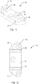
- each opening 60, 62 has a first portion 64 with a first length L1 and a second portion 66 with a second length L2 greater than the first length.
- the second portion 66 has a curved shape at a bottom thereof having a first radius for receiving a circular portion of a bumper.
- the first radius is equal to half the second length.
- the protrusions are angled relative to the top surfaces of the bar members 50 and 52 to allow a face of the door 16 to contact bumpers on the latch bar 20 rather than an edge of the door when the swing bar door guard is in a blocking position.
- the protrusions 56 and 58 are angled outward from the bar members 50 and 52 in a direction from an end of the bar members 50 and 52 opposite the curved member 54 toward the curved member 54.
- Each ear 70, 72 is configured to abut the respective ear 28, 30 of the latch base 18 and has a respective openings 74, 76 configured to be aligned with the respective opening 32, 34 in the ears 28 and 30 of the latch base 18.
- the openings 74 and 76 are threaded to engage threads of the fasteners 36 and 38.
- the door latch 12 additionally includes a pair of bumpers 80 and 82 configured to be received in and extend past each end of the openings 60 and 62 to reduce or eliminate noise when the swing bar door guard is in the blocking position.
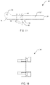
- Each bumper 80 includes a base 84, also referred to as a jamb bumper, having a third length greater than the first and second lengths, a post 86 extending from the base 84 having a fourth length less than or equal to the first length, and a substantially circular portion 88, also referred to as a door bumper, extending from the post 86 and having a second radius less than or equal to the first radius.
- the circular portion 88 has an opening 90 extending therethrough that allows the circular portion to deflect downward during installation and in use.
- the openings 74 and 76 in the latch bar 20 are aligned with the respective openings 32 and 34 in the latch base 18 either before or after the latch base 18 has been attached to the door jamb 22.
- the fastener 36 is then inserted through the opening 32 and threaded through the opening 74 to connect the ear 28 to the ear 70, and the fastener 38 is inserted through the opening 34 and threaded through the opening 76 to connect the ear 30 to the ear 72.
- the bumpers 80 and 82 are attached to the latch bar 20.
- the door bumper 88 is inserted into the first portion 64 of the opening 60 from the backside of the bar member 50.
- the door bumper 88 is compressed to fit through the first portion 64 and is advanced into the second portion 66 where the door bumper 88 expands to sit within the second portion 66 and extend out of the opening 60.
- the post 86 is disposed in the first portion 64 and the jamb bumper 84 abuts the bottom surface of the bar member 50.
- the jamb bumper 84 has the third length greater than the first length to prevent the bumper 80 from being pulled out in one direction, and the door bumper 88 is sized to be larger than the first length to resist unintentional removal in the other direction. If a user desires to replace the bumper 80, the user grasps the jamb bumper 84 and pulls to cause the door bumper 88 to compress to allow removal.
- the door bumper 88 is inserted into the first portion 64 of the opening 62 from the backside of the bar member 52.
- the door bumper 88 is compressed to fit through the first portion 64 and is advanced into the second portion 66 where the door bumper 88 expands to sit within the second portion 66 and extend out of the opening 62.
- the post 86 is disposed in the first portion 64 and the jamb bumper 84 abuts the bottom surface of the bar member 52.
- the door hook 14 includes a body 100 having a bottom surface that abuts the door 16 and one or more openings 102, such as four openings as shown, for receiving fasteners to secure the body 100 to the door 16.
- the openings 102 can be countersunk to receive a head of the fasteners.
- the door hook also includes an arm 104 extending from the body 100 with a knob 106 at an end of the arm 104.
- the door hook 14 is attached to the door 16 and the latch base 18 is attached to the door jamb 22 in any order.
- the bottom surface of the body 24 of the latch base 18 is placed against the door jamb 22 and the fasteners inserted through the openings 26 to secure the latch base 18 to the door jamb 22, and the bottom surface of the body 100 of the door hook 14 is placed against the door 16 and the fasteners inserted through the openings 102 to secure the door hook 14 to the door 16.
- the door hook 14 and the door latch 12 are aligned relative to another such that when the door 16 is in a closed position, the latch bar 20 can be moved over the arm 104 to prevent the door 16 from fully opening.
- the swing bar door guard and in particular the latch bar 20, is movable between the latched position shown in Fig. 1 , an unlatched position shown in Figs. 26-32 where the latch bar 20 is moved away from the arm 104 to allow to door 16 to be opened and closed, and to the blocking position shown in Figs. 9 and 10 .
- the latch bar 20 is moved away from the door 16 to the unlatched position to allow the door 16 to open.
- the latch bar 20 is then moved towards the door 16 when the door is in the opened position and movement is continued until the jamb bumpers 84 on the bumpers 80 and 82 contact the door jamb 22.
- the swing bar door guard 10 thereby prevents the door from being damaged by eliminating contact with a metal portion of a door guard and reduces or eliminates noise associated with a door slamming against the metal portion of the door guard and the door guard slamming against a door jamb.
- the outside face of the door 16 contacts the door bumpers 88 in the blocking position rather than the edge of the door to more evenly distribute the impact force.
- the bumpers 80 and 82 thereby provide a direct load path from the door 16, through the bumpers 80 and 82, and into the door jamb 22 to reduce wear and tear on the swing bar door guard 10.
- both the jamb bumpers 84 and the door bumpers 88 both the door 16 and door jamb 22 are protected and noise is reduced or prevented from contact with both the door 16 and door jamb 22.
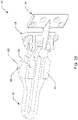
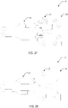
- FIG. 33 and 34 an exemplary embodiment of a door latch is shown at 112.
- the door latch 112 is substantially the same as the abovereferenced latch bar 112, and consequently the same reference numerals but indexed by 100 are used to denote structures corresponding to similar structures in the door latches.
- the foregoing description of the door latch 12 is equally applicable to the door latch 112 except as noted below.
- the door latch 112 includes a latch base 118 and a latch bar 120 configured to be coupled to the latch base 118.
- the latch base 118 includes a body 124 with one or more openings 126 for receiving fasteners, and a pair of ears 128 and 130 extending from a top surface of the body 124 and having a respective opening 132 for receiving a respective fastener for securing the latch bar 120 to the latch base 118.
- the latch bar 120 includes a base 140, an adjustable retainer 142 movable relative to the base to adjust a length of the latch bar 120, a bumper 180 attached to the adjustable retainer 142 and having an opening 190 extending therethrough, and a bumper 182 attached to the base 140.
- the latch bar 120 includes ears 170 and 172 for aligning with the ears on the latch base 118.
- the adjustable retainer 142 may be held in position relative to the base 140 by a fastener 146, such as a set screw, and includes a through passage through which the base moves. An end 141 of the base is shown extending through the passage.
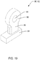
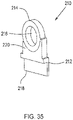
- the bumper assembly 210 may be attached to a latch bar, such as a latch bar having a pair of parallel bar members.
- the bumper assembly 210 includes a body 212 and a bumper 214 attached to the body 212.
- the bumper 214 includes an opening 216 extending therethrough to assist in deflection of the bumper.
- the body 212 has an L-shaped portion 218 for attachment to one of the bar members and a protrusion portion 220 to which the bumper attaches.
Landscapes
- Engineering & Computer Science (AREA)
- Mechanical Engineering (AREA)
- Wing Frames And Configurations (AREA)
- Lock And Its Accessories (AREA)
- Closing And Opening Devices For Wings, And Checks For Wings (AREA)
- Gates (AREA)
- Special Wing (AREA)
- Platform Screen Doors And Railroad Systems (AREA)
Claims (12)
- Eine Türschließe (12) für eine schwenkbare Türsicherung (10), wobei die Türschließe umfasst:
einen Verriegelungsbügel (20) mit einem Körper, der ein Paar paralleler Stabelemente (50, 52),einen Vorsprung (56, 58), der sich von einer oberen Fläche eines jeden der parallelen Stabelemente erstreckt,eine Öffnung (60, 62), die sich durch jedes parallele Stabelement und den jeweiligen Vorsprung (56, 58) erstreckt,eine Lasche (70, 72), die sich von Enden des jeweiligen parallelen Stabelements (50, 52) erstreckt, undeine Öffnung (74, 76), die sich durch jede Lasche (70, 72) hindurcherstreckt, um den Verriegelungsbügel (20) mit einer Schließenbasis (18) zu verbinden, und
ein Paar Stoßelemente (80, 82), dazu ausgestaltet, sich durch jeweils eine der Öffnungen (60, 62) zu erstrecken, wobei jedes Stoßelement (80, 82) einen Anschlagstoßabschnitt (84) aufweist, welcher dazu ausgestaltet ist, mit einem Türstock und einem Türstoßabschnitt (88), der dazu ausgestaltet ist, eine Türe zu kontaktieren, in Kontakt zu treten. - Die Türschließe gemäß Anspruch 1, mit einer Schließenbasis (18), dieeinen Körper (24), welcher eine untere Fläche aufweist, die dazu ausgestaltet ist, an einen Türstock anzugrenzen,eine oder mehrere Öffnungen (26), die sich durch den Körper hindurcherstrecken, um Befestigungsmittel aufzunehmen, um den Körper an dem Türstock festzulegen,ein Paar Laschen (28, 30), die sich von einer oberen Fläche des Körpers parallel zu einander und beabstandet von einander entlang einer Länge des Körpers erstrecken, undeine Öffnung (32, 34), die sich durch jede Lasche (28, 30) hindurcherstreckt, um mit jeweils einer der Öffnungen (74, 76) in den Laschen (70, 72) der parallelen Stabelemente (50, 52) ausgerichtet zu sein,aufweist.
- Die Türschließe gemäß den Ansprüchen 1 oder 2, wobei sich jeder Vorsprung (56, 58) von der oberen Fläche des jeweils parallelen Stabelements (50, 52) unter einem Winkel, relativ zu der bezogenen oberen Fläche, erstreckt.
- Die Türschließe, gemäß einem der Ansprüche 1 bis 3, wobei jeder Türstoßabschnitt (88) einen kreisförmigen Abschnitt umfasst, der eine Öffnung (90) aufweist, welche sich dadurch erstreckt.
- Eine schwenkbare Türsicherung, umfassend:die Türschließe, gemäß Anspruch 1, wobei die Türschließe zusätzlich eine Schließenbasis (18) umfasst, die dazu ausgestaltet ist, mit dem Türstock und dem Verriegelungsbügel (20) verbunden zu werden, undeinen Türhaken (14), der dazu ausgestaltet ist, mit der Tür verbunden zu werden, wobei der Verriegelungsbügel beweglich zwischen einer entriegelten Position, um ein Öffnen und Schließen der Tür zu ermöglichen, einer eingeklinkten Position, um vollständiges Öffnen der Türe zu verhindern, und einer gesperrten Position, um ein Schließen der Tür zu verhindern, ist, und wobei in der gesperrten Position, der Anschlagstoßabschnitt (84) den Türstock kontaktiert und der Türstoßabschnitt (88) die Türe kontaktiert.
- Die schwenkbare Türsicherung, gemäß Anspruch 5, wobei die Anschlagstoßabschnitte (84) dazu ausgestaltet sind, sich über ein Ende der jeweils ersten und zweiten Öffnung zu erstrecken, um den Türstock zu kontaktieren, und
die Türstoßabschnitte (88) dazu ausgestaltet sind, sich über ein weiteres Ende der jeweils ersten und zweiten Öffnung hinaus zu erstrecken, um die Tür zu kontaktieren. - Die schwenkbare Türsicherung, gemäß Anspruch 6, wobei die Türstoßabschnitte (88) jeweils einen, eine durchdringende Öffnung (90) aufweisenden, kreisförmigen Abschnitt umfassen.
- Die schwenkbare Türsicherung, gemäß Anspruch 6 oder 7, wobei die ersten und zweiten Stoßelemente (80, 82) jeweilsden Anschlagstoßabschnitt (84),den Türstoßabschnitt (88) undeinen Steg (86), der den Anschlagstoßabschnitt (84) mit dem Türstoßabschnitt (88) verbindet,umfassen.
- Die schwenkbare Türsicherung, gemäß einem der Ansprüche 6 bis 8, wobei jeder Anschlagstoßabschnitt (84) eine Länge aufweist, die größer als eine Länge der jeweils ersten und zweiten Öffnung bei dem ersten und zweiten parallelen Stabelement (50, 52) ist, um die Anschlagstoßabschnitte (84) davon abzuhalten, in die Öffnungen einzudringen.
- Die schwenkbare Türsicherung, gemäß einem der Ansprüche 5 bis 9, wobei sich die ersten und zweiten Vorsprünge (56, 58) von der oberen Fläche der jeweils ersten und zweiten parallelen Stabelemente (50, 52) unter einem Winkel, relativ zu den oberen Flächen, erstrecken.
- Die schwenkbare Türsicherung, gemäß einem der Ansprüche 5 bis 10, wobei die Schließenbasis (18)einen Körper (24), welcher eine untere Fläche aufweist, die dazu ausgestaltet ist, an einen Türstock anzustoßen,eine oder mehrere Öffnungen (26), die sich durch den Körper (24) erstrecken, um Befestigungsmittel aufzunehmen, um den Körper (24) an den Türstock festzulegen,ein Paar Laschen (28, 30), die sich von der oberen Fläche des Körpers (24) parallel zu einander und beabstandet von einander entlang einer Länge des Körpers (24) erstrecken, undeine Öffnung (32, 34), die sich durch jede Lasche (28, 30) hindurcherstreckt, umfasst.
- Die schwenkbare Türsicherung, gemäß einem der Ansprüche 5 bis 11, wobei der Türhaken (14)einen Körper, der eine untere Fläche aufweist, die dazu ausgestaltet ist, an der Tür anzustoßen,eine oder mehrere Öffnungen, die sich durch den Körper hindurcherstrecken, um Befestigungsmittel aufzunehmen, um den Körper an der Türe festzulegen,einen Arm, der sich von dem Körper erstreckt,und einen Knauf an einem Ende des Armsumfasst.
Applications Claiming Priority (2)
| Application Number | Priority Date | Filing Date | Title |
|---|---|---|---|
| US201762553225P | 2017-09-01 | 2017-09-01 | |
| PCT/US2018/048542 WO2019046424A1 (en) | 2017-09-01 | 2018-08-29 | OSCILLATING BAR DOOR PROTECTION |
Publications (3)
| Publication Number | Publication Date |
|---|---|
| EP3676469A1 EP3676469A1 (de) | 2020-07-08 |
| EP3676469A4 EP3676469A4 (de) | 2021-06-09 |
| EP3676469B1 true EP3676469B1 (de) | 2023-01-25 |
Family
ID=65517802
Family Applications (1)
| Application Number | Title | Priority Date | Filing Date |
|---|---|---|---|
| EP18850126.6A Active EP3676469B1 (de) | 2017-09-01 | 2018-08-29 | Schwingstangentürschuz |
Country Status (12)
| Country | Link |
|---|---|
| US (1) | US11319736B2 (de) |
| EP (1) | EP3676469B1 (de) |
| JP (1) | JP2021503572A (de) |
| KR (1) | KR20200038544A (de) |
| CN (1) | CN111108257B (de) |
| AU (1) | AU2018323554A1 (de) |
| BR (1) | BR112020004029A2 (de) |
| CA (1) | CA3074209A1 (de) |
| CL (1) | CL2020000481A1 (de) |
| MX (1) | MX2020002293A (de) |
| RU (1) | RU2020112526A (de) |
| WO (1) | WO2019046424A1 (de) |
Families Citing this family (3)
| Publication number | Priority date | Publication date | Assignee | Title |
|---|---|---|---|---|
| US11371273B2 (en) * | 2018-08-21 | 2022-06-28 | Sam Casternovia | Guard for a latch to prevent opening |
| KR102448260B1 (ko) * | 2022-07-13 | 2022-09-27 | 윤중재 | 여닫이문의 충격소음 방지장치 |
| US20240392619A1 (en) * | 2023-05-25 | 2024-11-28 | Elvis Torrealba | Shock Absorber Device for Protecting a Door and Door Frame |
Family Cites Families (20)
| Publication number | Priority date | Publication date | Assignee | Title |
|---|---|---|---|---|
| US4062578A (en) * | 1976-12-27 | 1977-12-13 | Trepege Products Inc. | Door safety latch |
| AU576047B2 (en) * | 1985-01-14 | 1988-08-11 | Shiseido Company Ltd. | Fibrinophilic urokinase complex and process for its preparation |
| JP2559590Y2 (ja) * | 1991-02-14 | 1998-01-19 | 株式会社竹中工務店 | ドアガード |
| JPH0647554U (ja) * | 1992-12-09 | 1994-06-28 | リョービ株式会社 | ドアガード |
| JP2568045Y2 (ja) * | 1993-05-21 | 1998-04-08 | 株式会社竹中工務店 | ドアガード用緩衝部材 |
| JP2521438Y2 (ja) * | 1993-08-23 | 1996-12-25 | 三和ダイカスト株式会社 | 戸用心金具 |
| JP2604481Y2 (ja) | 1993-09-03 | 2000-05-15 | 株式会社ホテル小田急 | ドアガード |
| JP3013988U (ja) * | 1995-01-25 | 1995-07-25 | 三和ダイカスト株式会社 | 弾性ゴムの挿入埋込装置 |
| CN1207479C (zh) * | 1999-07-22 | 2005-06-22 | 思嘎茨讷工业株式会社 | 门定位器 |
| JP2001090419A (ja) * | 1999-09-27 | 2001-04-03 | Okuda Seisakusho:Kk | ドアの用心錠とそのストッパー |
| US7360804B1 (en) | 2006-12-14 | 2008-04-22 | Senduay Corp | Articles, systems, and methods for suppressing noise and/or vibrations in hotel/motel doors |
| WO2008115436A1 (en) * | 2007-03-15 | 2008-09-25 | Yates Kristian W | Door latch |
| US9316033B2 (en) * | 2007-03-15 | 2016-04-19 | Kristian W. Yates | Door safety latch |
| JP4994308B2 (ja) * | 2008-06-04 | 2012-08-08 | ダイハツ工業株式会社 | 荷箱用ゲートハンドルの緩衝部材組み付け構造及び該緩衝部材の組み付け方法 |
| US7905525B2 (en) * | 2008-12-19 | 2011-03-15 | James Badia | Security latch device with a latching arm cover |
| USD643278S1 (en) * | 2010-08-24 | 2011-08-16 | Senduzy Corp. | Hotel door sound suppressor (HDSS) |
| RU2514487C1 (ru) | 2013-04-22 | 2014-04-27 | Валерий Николаевич Толочек | Ограничитель просвета открывания створки |
| TWM475499U (en) * | 2013-10-03 | 2014-04-01 | Shih Ming Hwang | Structure of door bolt |
| US20160362911A1 (en) * | 2015-06-12 | 2016-12-15 | Hotel Solutions Inc. | Swing Bolt Lock Sleeve |
| US10975602B2 (en) * | 2015-11-11 | 2021-04-13 | Alan B Kingsbury | Security latch for a swing bar door guard |
-
2018
- 2018-08-29 AU AU2018323554A patent/AU2018323554A1/en not_active Abandoned
- 2018-08-29 CA CA3074209A patent/CA3074209A1/en active Pending
- 2018-08-29 JP JP2020534795A patent/JP2021503572A/ja active Pending
- 2018-08-29 US US16/116,387 patent/US11319736B2/en active Active
- 2018-08-29 BR BR112020004029-0A patent/BR112020004029A2/pt not_active Application Discontinuation
- 2018-08-29 EP EP18850126.6A patent/EP3676469B1/de active Active
- 2018-08-29 MX MX2020002293A patent/MX2020002293A/es unknown
- 2018-08-29 CN CN201880056976.7A patent/CN111108257B/zh active Active
- 2018-08-29 KR KR1020207009136A patent/KR20200038544A/ko not_active Ceased
- 2018-08-29 WO PCT/US2018/048542 patent/WO2019046424A1/en not_active Ceased
- 2018-08-29 RU RU2020112526A patent/RU2020112526A/ru not_active Application Discontinuation
-
2020
- 2020-02-27 CL CL2020000481A patent/CL2020000481A1/es unknown
Also Published As
| Publication number | Publication date |
|---|---|
| CL2020000481A1 (es) | 2020-11-27 |
| RU2020112526A (ru) | 2021-10-01 |
| US20190071903A1 (en) | 2019-03-07 |
| JP2021503572A (ja) | 2021-02-12 |
| RU2020112526A3 (de) | 2021-12-03 |
| WO2019046424A1 (en) | 2019-03-07 |
| AU2018323554A1 (en) | 2020-04-30 |
| US11319736B2 (en) | 2022-05-03 |
| CN111108257A (zh) | 2020-05-05 |
| CN111108257B (zh) | 2022-05-06 |
| CA3074209A1 (en) | 2019-03-07 |
| BR112020004029A2 (pt) | 2020-09-08 |
| EP3676469A1 (de) | 2020-07-08 |
| KR20200038544A (ko) | 2020-04-13 |
| EP3676469A4 (de) | 2021-06-09 |
| MX2020002293A (es) | 2020-10-22 |
Similar Documents
| Publication | Publication Date | Title |
|---|---|---|
| US8595899B2 (en) | Door jamb injury protector | |
| US3172168A (en) | Retractable door stop | |
| EP3676469B1 (de) | Schwingstangentürschuz | |
| US3977714A (en) | Stop assembly | |
| US20090260182A1 (en) | Anti-movement device for closure member | |
| US10501974B2 (en) | Fitting arrangement for connecting a slidable and tiltable leaf | |
| US5732986A (en) | Door lock | |
| US7472514B2 (en) | Window, door or the like comprising a swinging arms assembly with stop means | |
| US4189175A (en) | Door strike | |
| US11391068B2 (en) | Door security assembly | |
| US3892434A (en) | Toggle-action fastener | |
| US20080264119A1 (en) | Lock | |
| WO2004013438A1 (en) | Restricting device | |
| KR102245818B1 (ko) | 여닫이문용 패널형 손끼임 방지구 | |
| US20050052035A1 (en) | Door security latch | |
| CN223269798U (zh) | 阻门器 | |
| JP3098207B2 (ja) | 引き戸用ストッパ装置 | |
| GB2576170A (en) | Letter plate | |
| KR200377856Y1 (ko) | 충돌 방지 기능을 갖는 래치 장치 | |
| KR200162331Y1 (ko) | 버스의 개폐 윈도우 잠금장치 | |
| WO1999060238A1 (en) | A partially concealed secondary locking device for use in sliding doors and/or windows | |
| JP3229807B2 (ja) | 扉の自然開放防止装置 | |
| GB2441143A (en) | Keep assembly allowing emergency bolt release | |
| CA2290456A1 (en) | Door lock | |
| GB2429033A (en) | Releasable keeper |
Legal Events
| Date | Code | Title | Description |
|---|---|---|---|
| STAA | Information on the status of an ep patent application or granted ep patent |
Free format text: STATUS: THE INTERNATIONAL PUBLICATION HAS BEEN MADE |
|
| PUAI | Public reference made under article 153(3) epc to a published international application that has entered the european phase |
Free format text: ORIGINAL CODE: 0009012 |
|
| STAA | Information on the status of an ep patent application or granted ep patent |
Free format text: STATUS: REQUEST FOR EXAMINATION WAS MADE |
|
| 17P | Request for examination filed |
Effective date: 20200330 |
|
| AK | Designated contracting states |
Kind code of ref document: A1 Designated state(s): AL AT BE BG CH CY CZ DE DK EE ES FI FR GB GR HR HU IE IS IT LI LT LU LV MC MK MT NL NO PL PT RO RS SE SI SK SM TR |
|
| AX | Request for extension of the european patent |
Extension state: BA ME |
|
| RAP1 | Party data changed (applicant data changed or rights of an application transferred) |
Owner name: QUIET LOCK CORPORATION |
|
| RIN1 | Information on inventor provided before grant (corrected) |
Inventor name: THOMAS, SCOTT |
|
| DAV | Request for validation of the european patent (deleted) | ||
| DAX | Request for extension of the european patent (deleted) | ||
| REG | Reference to a national code |
Ref country code: DE Ref legal event code: R079 Ref document number: 602018045826 Country of ref document: DE Free format text: PREVIOUS MAIN CLASS: E05C0017140000 Ipc: E05C0017160000 |
|
| A4 | Supplementary search report drawn up and despatched |
Effective date: 20210510 |
|
| RIC1 | Information provided on ipc code assigned before grant |
Ipc: E05C 17/16 20060101AFI20210503BHEP Ipc: E05D 3/08 20060101ALI20210503BHEP |
|
| GRAP | Despatch of communication of intention to grant a patent |
Free format text: ORIGINAL CODE: EPIDOSNIGR1 |
|
| STAA | Information on the status of an ep patent application or granted ep patent |
Free format text: STATUS: GRANT OF PATENT IS INTENDED |
|
| INTG | Intention to grant announced |
Effective date: 20220819 |
|
| GRAS | Grant fee paid |
Free format text: ORIGINAL CODE: EPIDOSNIGR3 |
|
| GRAA | (expected) grant |
Free format text: ORIGINAL CODE: 0009210 |
|
| STAA | Information on the status of an ep patent application or granted ep patent |
Free format text: STATUS: THE PATENT HAS BEEN GRANTED |
|
| AK | Designated contracting states |
Kind code of ref document: B1 Designated state(s): AL AT BE BG CH CY CZ DE DK EE ES FI FR GB GR HR HU IE IS IT LI LT LU LV MC MK MT NL NO PL PT RO RS SE SI SK SM TR |
|
| REG | Reference to a national code |
Ref country code: GB Ref legal event code: FG4D |
|
| RIN1 | Information on inventor provided before grant (corrected) |
Inventor name: THOMAS, SCOTT |
|
| REG | Reference to a national code |
Ref country code: CH Ref legal event code: EP |
|
| REG | Reference to a national code |
Ref country code: AT Ref legal event code: REF Ref document number: 1546018 Country of ref document: AT Kind code of ref document: T Effective date: 20230215 Ref country code: IE Ref legal event code: FG4D |
|
| REG | Reference to a national code |
Ref country code: DE Ref legal event code: R096 Ref document number: 602018045826 Country of ref document: DE |
|
| REG | Reference to a national code |
Ref country code: LT Ref legal event code: MG9D |
|
| REG | Reference to a national code |
Ref country code: NL Ref legal event code: MP Effective date: 20230125 |
|
| REG | Reference to a national code |
Ref country code: AT Ref legal event code: MK05 Ref document number: 1546018 Country of ref document: AT Kind code of ref document: T Effective date: 20230125 |
|
| PG25 | Lapsed in a contracting state [announced via postgrant information from national office to epo] |
Ref country code: NL Free format text: LAPSE BECAUSE OF FAILURE TO SUBMIT A TRANSLATION OF THE DESCRIPTION OR TO PAY THE FEE WITHIN THE PRESCRIBED TIME-LIMIT Effective date: 20230125 |
|
| P01 | Opt-out of the competence of the unified patent court (upc) registered |
Effective date: 20230608 |
|
| PG25 | Lapsed in a contracting state [announced via postgrant information from national office to epo] |
Ref country code: RS Free format text: LAPSE BECAUSE OF FAILURE TO SUBMIT A TRANSLATION OF THE DESCRIPTION OR TO PAY THE FEE WITHIN THE PRESCRIBED TIME-LIMIT Effective date: 20230125 Ref country code: PT Free format text: LAPSE BECAUSE OF FAILURE TO SUBMIT A TRANSLATION OF THE DESCRIPTION OR TO PAY THE FEE WITHIN THE PRESCRIBED TIME-LIMIT Effective date: 20230525 Ref country code: NO Free format text: LAPSE BECAUSE OF FAILURE TO SUBMIT A TRANSLATION OF THE DESCRIPTION OR TO PAY THE FEE WITHIN THE PRESCRIBED TIME-LIMIT Effective date: 20230425 Ref country code: LV Free format text: LAPSE BECAUSE OF FAILURE TO SUBMIT A TRANSLATION OF THE DESCRIPTION OR TO PAY THE FEE WITHIN THE PRESCRIBED TIME-LIMIT Effective date: 20230125 Ref country code: LT Free format text: LAPSE BECAUSE OF FAILURE TO SUBMIT A TRANSLATION OF THE DESCRIPTION OR TO PAY THE FEE WITHIN THE PRESCRIBED TIME-LIMIT Effective date: 20230125 Ref country code: HR Free format text: LAPSE BECAUSE OF FAILURE TO SUBMIT A TRANSLATION OF THE DESCRIPTION OR TO PAY THE FEE WITHIN THE PRESCRIBED TIME-LIMIT Effective date: 20230125 Ref country code: ES Free format text: LAPSE BECAUSE OF FAILURE TO SUBMIT A TRANSLATION OF THE DESCRIPTION OR TO PAY THE FEE WITHIN THE PRESCRIBED TIME-LIMIT Effective date: 20230125 Ref country code: AT Free format text: LAPSE BECAUSE OF FAILURE TO SUBMIT A TRANSLATION OF THE DESCRIPTION OR TO PAY THE FEE WITHIN THE PRESCRIBED TIME-LIMIT Effective date: 20230125 |
|
| PG25 | Lapsed in a contracting state [announced via postgrant information from national office to epo] |
Ref country code: SE Free format text: LAPSE BECAUSE OF FAILURE TO SUBMIT A TRANSLATION OF THE DESCRIPTION OR TO PAY THE FEE WITHIN THE PRESCRIBED TIME-LIMIT Effective date: 20230125 Ref country code: PL Free format text: LAPSE BECAUSE OF FAILURE TO SUBMIT A TRANSLATION OF THE DESCRIPTION OR TO PAY THE FEE WITHIN THE PRESCRIBED TIME-LIMIT Effective date: 20230125 Ref country code: IS Free format text: LAPSE BECAUSE OF FAILURE TO SUBMIT A TRANSLATION OF THE DESCRIPTION OR TO PAY THE FEE WITHIN THE PRESCRIBED TIME-LIMIT Effective date: 20230525 Ref country code: GR Free format text: LAPSE BECAUSE OF FAILURE TO SUBMIT A TRANSLATION OF THE DESCRIPTION OR TO PAY THE FEE WITHIN THE PRESCRIBED TIME-LIMIT Effective date: 20230426 Ref country code: FI Free format text: LAPSE BECAUSE OF FAILURE TO SUBMIT A TRANSLATION OF THE DESCRIPTION OR TO PAY THE FEE WITHIN THE PRESCRIBED TIME-LIMIT Effective date: 20230125 |
|
| REG | Reference to a national code |
Ref country code: DE Ref legal event code: R097 Ref document number: 602018045826 Country of ref document: DE |
|
| PG25 | Lapsed in a contracting state [announced via postgrant information from national office to epo] |
Ref country code: SM Free format text: LAPSE BECAUSE OF FAILURE TO SUBMIT A TRANSLATION OF THE DESCRIPTION OR TO PAY THE FEE WITHIN THE PRESCRIBED TIME-LIMIT Effective date: 20230125 Ref country code: RO Free format text: LAPSE BECAUSE OF FAILURE TO SUBMIT A TRANSLATION OF THE DESCRIPTION OR TO PAY THE FEE WITHIN THE PRESCRIBED TIME-LIMIT Effective date: 20230125 Ref country code: EE Free format text: LAPSE BECAUSE OF FAILURE TO SUBMIT A TRANSLATION OF THE DESCRIPTION OR TO PAY THE FEE WITHIN THE PRESCRIBED TIME-LIMIT Effective date: 20230125 Ref country code: DK Free format text: LAPSE BECAUSE OF FAILURE TO SUBMIT A TRANSLATION OF THE DESCRIPTION OR TO PAY THE FEE WITHIN THE PRESCRIBED TIME-LIMIT Effective date: 20230125 Ref country code: CZ Free format text: LAPSE BECAUSE OF FAILURE TO SUBMIT A TRANSLATION OF THE DESCRIPTION OR TO PAY THE FEE WITHIN THE PRESCRIBED TIME-LIMIT Effective date: 20230125 |
|
| PG25 | Lapsed in a contracting state [announced via postgrant information from national office to epo] |
Ref country code: SK Free format text: LAPSE BECAUSE OF FAILURE TO SUBMIT A TRANSLATION OF THE DESCRIPTION OR TO PAY THE FEE WITHIN THE PRESCRIBED TIME-LIMIT Effective date: 20230125 |
|
| PLBE | No opposition filed within time limit |
Free format text: ORIGINAL CODE: 0009261 |
|
| STAA | Information on the status of an ep patent application or granted ep patent |
Free format text: STATUS: NO OPPOSITION FILED WITHIN TIME LIMIT |
|
| 26N | No opposition filed |
Effective date: 20231026 |
|
| PG25 | Lapsed in a contracting state [announced via postgrant information from national office to epo] |
Ref country code: SI Free format text: LAPSE BECAUSE OF FAILURE TO SUBMIT A TRANSLATION OF THE DESCRIPTION OR TO PAY THE FEE WITHIN THE PRESCRIBED TIME-LIMIT Effective date: 20230125 |
|
| PG25 | Lapsed in a contracting state [announced via postgrant information from national office to epo] |
Ref country code: MC Free format text: LAPSE BECAUSE OF FAILURE TO SUBMIT A TRANSLATION OF THE DESCRIPTION OR TO PAY THE FEE WITHIN THE PRESCRIBED TIME-LIMIT Effective date: 20230125 |
|
| REG | Reference to a national code |
Ref country code: CH Ref legal event code: PL |
|
| PG25 | Lapsed in a contracting state [announced via postgrant information from national office to epo] |
Ref country code: MC Free format text: LAPSE BECAUSE OF FAILURE TO SUBMIT A TRANSLATION OF THE DESCRIPTION OR TO PAY THE FEE WITHIN THE PRESCRIBED TIME-LIMIT Effective date: 20230125 |
|
| PG25 | Lapsed in a contracting state [announced via postgrant information from national office to epo] |
Ref country code: LU Free format text: LAPSE BECAUSE OF NON-PAYMENT OF DUE FEES Effective date: 20230829 |
|
| PG25 | Lapsed in a contracting state [announced via postgrant information from national office to epo] |
Ref country code: LU Free format text: LAPSE BECAUSE OF NON-PAYMENT OF DUE FEES Effective date: 20230829 Ref country code: CH Free format text: LAPSE BECAUSE OF NON-PAYMENT OF DUE FEES Effective date: 20230831 |
|
| REG | Reference to a national code |
Ref country code: BE Ref legal event code: MM Effective date: 20230831 |
|
| REG | Reference to a national code |
Ref country code: IE Ref legal event code: MM4A |
|
| PG25 | Lapsed in a contracting state [announced via postgrant information from national office to epo] |
Ref country code: IT Free format text: LAPSE BECAUSE OF FAILURE TO SUBMIT A TRANSLATION OF THE DESCRIPTION OR TO PAY THE FEE WITHIN THE PRESCRIBED TIME-LIMIT Effective date: 20230125 |
|
| PG25 | Lapsed in a contracting state [announced via postgrant information from national office to epo] |
Ref country code: IE Free format text: LAPSE BECAUSE OF NON-PAYMENT OF DUE FEES Effective date: 20230829 |
|
| PG25 | Lapsed in a contracting state [announced via postgrant information from national office to epo] |
Ref country code: IE Free format text: LAPSE BECAUSE OF NON-PAYMENT OF DUE FEES Effective date: 20230829 |
|
| PG25 | Lapsed in a contracting state [announced via postgrant information from national office to epo] |
Ref country code: BE Free format text: LAPSE BECAUSE OF NON-PAYMENT OF DUE FEES Effective date: 20230831 |
|
| PG25 | Lapsed in a contracting state [announced via postgrant information from national office to epo] |
Ref country code: BG Free format text: LAPSE BECAUSE OF FAILURE TO SUBMIT A TRANSLATION OF THE DESCRIPTION OR TO PAY THE FEE WITHIN THE PRESCRIBED TIME-LIMIT Effective date: 20230125 |
|
| PG25 | Lapsed in a contracting state [announced via postgrant information from national office to epo] |
Ref country code: BG Free format text: LAPSE BECAUSE OF FAILURE TO SUBMIT A TRANSLATION OF THE DESCRIPTION OR TO PAY THE FEE WITHIN THE PRESCRIBED TIME-LIMIT Effective date: 20230125 |
|
| PG25 | Lapsed in a contracting state [announced via postgrant information from national office to epo] |
Ref country code: CY Free format text: LAPSE BECAUSE OF FAILURE TO SUBMIT A TRANSLATION OF THE DESCRIPTION OR TO PAY THE FEE WITHIN THE PRESCRIBED TIME-LIMIT; INVALID AB INITIO Effective date: 20180829 |
|
| PG25 | Lapsed in a contracting state [announced via postgrant information from national office to epo] |
Ref country code: HU Free format text: LAPSE BECAUSE OF FAILURE TO SUBMIT A TRANSLATION OF THE DESCRIPTION OR TO PAY THE FEE WITHIN THE PRESCRIBED TIME-LIMIT; INVALID AB INITIO Effective date: 20180829 |
|
| PGFP | Annual fee paid to national office [announced via postgrant information from national office to epo] |
Ref country code: DE Payment date: 20250819 Year of fee payment: 8 |
|
| PGFP | Annual fee paid to national office [announced via postgrant information from national office to epo] |
Ref country code: GB Payment date: 20250819 Year of fee payment: 8 |
|
| PGFP | Annual fee paid to national office [announced via postgrant information from national office to epo] |
Ref country code: FR Payment date: 20250818 Year of fee payment: 8 |
|
| PG25 | Lapsed in a contracting state [announced via postgrant information from national office to epo] |
Ref country code: TR Free format text: LAPSE BECAUSE OF FAILURE TO SUBMIT A TRANSLATION OF THE DESCRIPTION OR TO PAY THE FEE WITHIN THE PRESCRIBED TIME-LIMIT Effective date: 20230125 |