EP3676034B1 - Feuerfeste auskleidungsstruktur - Google Patents
Feuerfeste auskleidungsstruktur Download PDFInfo
- Publication number
- EP3676034B1 EP3676034B1 EP18849678.0A EP18849678A EP3676034B1 EP 3676034 B1 EP3676034 B1 EP 3676034B1 EP 18849678 A EP18849678 A EP 18849678A EP 3676034 B1 EP3676034 B1 EP 3676034B1
- Authority
- EP
- European Patent Office
- Prior art keywords
- layer
- elongated expansion
- refractory
- tundish
- sidewall
- Prior art date
- Legal status (The legal status is an assumption and is not a legal conclusion. Google has not performed a legal analysis and makes no representation as to the accuracy of the status listed.)
- Active
Links
- 239000011819 refractory material Substances 0.000 claims description 77
- CPLXHLVBOLITMK-UHFFFAOYSA-N magnesium oxide Inorganic materials [Mg]=O CPLXHLVBOLITMK-UHFFFAOYSA-N 0.000 claims description 25
- TWNQGVIAIRXVLR-UHFFFAOYSA-N oxo(oxoalumanyloxy)alumane Chemical compound O=[Al]O[Al]=O TWNQGVIAIRXVLR-UHFFFAOYSA-N 0.000 claims description 19
- 239000000395 magnesium oxide Substances 0.000 claims description 17
- 238000009749 continuous casting Methods 0.000 claims description 14
- AXZKOIWUVFPNLO-UHFFFAOYSA-N magnesium;oxygen(2-) Chemical compound [O-2].[Mg+2] AXZKOIWUVFPNLO-UHFFFAOYSA-N 0.000 claims description 11
- RVTZCBVAJQQJTK-UHFFFAOYSA-N oxygen(2-);zirconium(4+) Chemical compound [O-2].[O-2].[Zr+4] RVTZCBVAJQQJTK-UHFFFAOYSA-N 0.000 claims description 8
- 229910001928 zirconium oxide Inorganic materials 0.000 claims description 8
- VYZAMTAEIAYCRO-UHFFFAOYSA-N Chromium Chemical compound [Cr] VYZAMTAEIAYCRO-UHFFFAOYSA-N 0.000 claims description 5
- 125000006850 spacer group Chemical group 0.000 description 23
- 229910000831 Steel Inorganic materials 0.000 description 20
- 239000010959 steel Substances 0.000 description 20
- PNEYBMLMFCGWSK-UHFFFAOYSA-N aluminium oxide Inorganic materials [O-2].[O-2].[O-2].[Al+3].[Al+3] PNEYBMLMFCGWSK-UHFFFAOYSA-N 0.000 description 17
- MCMNRKCIXSYSNV-UHFFFAOYSA-N Zirconium dioxide Chemical compound O=[Zr]=O MCMNRKCIXSYSNV-UHFFFAOYSA-N 0.000 description 16
- 229910052751 metal Inorganic materials 0.000 description 13
- 239000002184 metal Substances 0.000 description 13
- 239000000463 material Substances 0.000 description 11
- 239000002893 slag Substances 0.000 description 11
- QDOXWKRWXJOMAK-UHFFFAOYSA-N dichromium trioxide Chemical compound O=[Cr]O[Cr]=O QDOXWKRWXJOMAK-UHFFFAOYSA-N 0.000 description 10
- 239000011120 plywood Substances 0.000 description 9
- VYPSYNLAJGMNEJ-UHFFFAOYSA-N Silicium dioxide Chemical compound O=[Si]=O VYPSYNLAJGMNEJ-UHFFFAOYSA-N 0.000 description 8
- 238000000034 method Methods 0.000 description 8
- 210000003625 skull Anatomy 0.000 description 8
- 238000005266 casting Methods 0.000 description 7
- 238000010438 heat treatment Methods 0.000 description 7
- 230000032798 delamination Effects 0.000 description 5
- UQSXHKLRYXJYBZ-UHFFFAOYSA-N iron oxide Inorganic materials [Fe]=O UQSXHKLRYXJYBZ-UHFFFAOYSA-N 0.000 description 5
- 238000004901 spalling Methods 0.000 description 5
- 238000005507 spraying Methods 0.000 description 5
- ODINCKMPIJJUCX-UHFFFAOYSA-N Calcium oxide Chemical compound [Ca]=O ODINCKMPIJJUCX-UHFFFAOYSA-N 0.000 description 4
- 239000000292 calcium oxide Substances 0.000 description 4
- 235000012255 calcium oxide Nutrition 0.000 description 4
- 238000005336 cracking Methods 0.000 description 4
- 235000013980 iron oxide Nutrition 0.000 description 4
- 229910052609 olivine Inorganic materials 0.000 description 4
- 239000010450 olivine Substances 0.000 description 4
- 239000000377 silicon dioxide Substances 0.000 description 4
- 239000000470 constituent Substances 0.000 description 3
- VBMVTYDPPZVILR-UHFFFAOYSA-N iron(2+);oxygen(2-) Chemical class [O-2].[Fe+2] VBMVTYDPPZVILR-UHFFFAOYSA-N 0.000 description 3
- 239000011823 monolithic refractory Substances 0.000 description 3
- 238000000926 separation method Methods 0.000 description 3
- 238000009628 steelmaking Methods 0.000 description 3
- 230000015572 biosynthetic process Effects 0.000 description 2
- 238000010586 diagram Methods 0.000 description 2
- KZHJGOXRZJKJNY-UHFFFAOYSA-N dioxosilane;oxo(oxoalumanyloxy)alumane Chemical group O=[Si]=O.O=[Si]=O.O=[Al]O[Al]=O.O=[Al]O[Al]=O.O=[Al]O[Al]=O KZHJGOXRZJKJNY-UHFFFAOYSA-N 0.000 description 2
- 239000010459 dolomite Substances 0.000 description 2
- 229910000514 dolomite Inorganic materials 0.000 description 2
- -1 for example Substances 0.000 description 2
- 230000005484 gravity Effects 0.000 description 2
- 230000001788 irregular Effects 0.000 description 2
- 238000010310 metallurgical process Methods 0.000 description 2
- 239000000126 substance Substances 0.000 description 2
- GFQYVLUOOAAOGM-UHFFFAOYSA-N zirconium(iv) silicate Chemical group [Zr+4].[O-][Si]([O-])([O-])[O-] GFQYVLUOOAAOGM-UHFFFAOYSA-N 0.000 description 2
- CWYNVVGOOAEACU-UHFFFAOYSA-N Fe2+ Chemical compound [Fe+2] CWYNVVGOOAEACU-UHFFFAOYSA-N 0.000 description 1
- QCWXUUIWCKQGHC-UHFFFAOYSA-N Zirconium Chemical compound [Zr] QCWXUUIWCKQGHC-UHFFFAOYSA-N 0.000 description 1
- 239000011449 brick Substances 0.000 description 1
- 239000011111 cardboard Substances 0.000 description 1
- 230000003247 decreasing effect Effects 0.000 description 1
- 238000001035 drying Methods 0.000 description 1
- 238000009413 insulation Methods 0.000 description 1
- 239000000203 mixture Substances 0.000 description 1
- 229910052863 mullite Inorganic materials 0.000 description 1
- 238000013021 overheating Methods 0.000 description 1
- 239000002245 particle Substances 0.000 description 1
- 230000000704 physical effect Effects 0.000 description 1
- 239000004033 plastic Substances 0.000 description 1
- 239000007787 solid Substances 0.000 description 1
- 238000010977 unit operation Methods 0.000 description 1
- XLYOFNOQVPJJNP-UHFFFAOYSA-N water Substances O XLYOFNOQVPJJNP-UHFFFAOYSA-N 0.000 description 1
- 239000002023 wood Substances 0.000 description 1
- 229910052726 zirconium Inorganic materials 0.000 description 1
Images


Classifications
-
- B—PERFORMING OPERATIONS; TRANSPORTING
- B22—CASTING; POWDER METALLURGY
- B22D—CASTING OF METALS; CASTING OF OTHER SUBSTANCES BY THE SAME PROCESSES OR DEVICES
- B22D41/00—Casting melt-holding vessels, e.g. ladles, tundishes, cups or the like
- B22D41/02—Linings
-
- B—PERFORMING OPERATIONS; TRANSPORTING
- B22—CASTING; POWDER METALLURGY
- B22D—CASTING OF METALS; CASTING OF OTHER SUBSTANCES BY THE SAME PROCESSES OR DEVICES
- B22D41/00—Casting melt-holding vessels, e.g. ladles, tundishes, cups or the like
- B22D41/003—Casting melt-holding vessels, e.g. ladles, tundishes, cups or the like with impact pads
-
- F—MECHANICAL ENGINEERING; LIGHTING; HEATING; WEAPONS; BLASTING
- F27—FURNACES; KILNS; OVENS; RETORTS
- F27D—DETAILS OR ACCESSORIES OF FURNACES, KILNS, OVENS, OR RETORTS, IN SO FAR AS THEY ARE OF KINDS OCCURRING IN MORE THAN ONE KIND OF FURNACE
- F27D1/00—Casings; Linings; Walls; Roofs
- F27D1/0003—Linings or walls
- F27D1/0023—Linings or walls comprising expansion joints or means to restrain expansion due to thermic flows
-
- F—MECHANICAL ENGINEERING; LIGHTING; HEATING; WEAPONS; BLASTING
- F27—FURNACES; KILNS; OVENS; RETORTS
- F27D—DETAILS OR ACCESSORIES OF FURNACES, KILNS, OVENS, OR RETORTS, IN SO FAR AS THEY ARE OF KINDS OCCURRING IN MORE THAN ONE KIND OF FURNACE
- F27D1/00—Casings; Linings; Walls; Roofs
- F27D1/10—Monolithic linings; Supports therefor
-
- B—PERFORMING OPERATIONS; TRANSPORTING
- B22—CASTING; POWDER METALLURGY
- B22D—CASTING OF METALS; CASTING OF OTHER SUBSTANCES BY THE SAME PROCESSES OR DEVICES
- B22D11/00—Continuous casting of metals, i.e. casting in indefinite lengths
- B22D11/10—Supplying or treating molten metal
-
- B—PERFORMING OPERATIONS; TRANSPORTING
- B22—CASTING; POWDER METALLURGY
- B22D—CASTING OF METALS; CASTING OF OTHER SUBSTANCES BY THE SAME PROCESSES OR DEVICES
- B22D41/00—Casting melt-holding vessels, e.g. ladles, tundishes, cups or the like
- B22D41/08—Casting melt-holding vessels, e.g. ladles, tundishes, cups or the like for bottom pouring
-
- C—CHEMISTRY; METALLURGY
- C04—CEMENTS; CONCRETE; ARTIFICIAL STONE; CERAMICS; REFRACTORIES
- C04B—LIME, MAGNESIA; SLAG; CEMENTS; COMPOSITIONS THEREOF, e.g. MORTARS, CONCRETE OR LIKE BUILDING MATERIALS; ARTIFICIAL STONE; CERAMICS; REFRACTORIES; TREATMENT OF NATURAL STONE
- C04B2235/00—Aspects relating to ceramic starting mixtures or sintered ceramic products
- C04B2235/70—Aspects relating to sintered or melt-casted ceramic products
- C04B2235/96—Properties of ceramic products, e.g. mechanical properties such as strength, toughness, wear resistance
- C04B2235/9669—Resistance against chemicals, e.g. against molten glass or molten salts
- C04B2235/9676—Resistance against chemicals, e.g. against molten glass or molten salts against molten metals such as steel or aluminium
-
- C—CHEMISTRY; METALLURGY
- C04—CEMENTS; CONCRETE; ARTIFICIAL STONE; CERAMICS; REFRACTORIES
- C04B—LIME, MAGNESIA; SLAG; CEMENTS; COMPOSITIONS THEREOF, e.g. MORTARS, CONCRETE OR LIKE BUILDING MATERIALS; ARTIFICIAL STONE; CERAMICS; REFRACTORIES; TREATMENT OF NATURAL STONE
- C04B35/00—Shaped ceramic products characterised by their composition; Ceramics compositions; Processing powders of inorganic compounds preparatory to the manufacturing of ceramic products
- C04B35/66—Monolithic refractories or refractory mortars, including those whether or not containing clay
Definitions
- molten metal is transported between unit operations in metallurgical vessels.
- molten steel is tapped from a steelmaking furnace into a ladle.
- the ladle functions as a transporting vessel within which the molten steel moves from the steelmaking furnace to a casting platform.
- the molten steel transfers from the ladle to a tundish.
- the tundish functions as a metering device that distributes the molten steel through one or more nozzles into molds in a continuous flow.
- Metallurgical vessels such as, for example, ladles and tundishes, must physically contain molten metal at relatively high temperatures, for example, in steelmaking processes, at temperatures greater than 1400°C (2552°F). Additionally, the molten metal-contacting surfaces of metallurgical vessels should be as chemically inert as possible with respect to the molten metal contained within the vessels. Accordingly, metallurgical vessels are lined with refractory materials to provide physically-stable and chemically-stable molten metal-contacting surfaces and insulation between the molten metal and the vessel shells, which are typically made of solid steel and therefore susceptible to overheating and loss of mechanical integrity if contacted by molten metal.
- the invention described in this specification is directed to refractory lining structures for metallurgical vessels.
- the invention described in this specification is also directed to metallurgical vessels comprising the refractory lining structures, methods for making the refractory lining structures and for making metallurgical vessels comprising the refractory lining structures, and methods of using metallurgical vessels comprising the refractory lining structures in metallurgical processes.
- the refractory lining structures provide improved mechanical stability and structural integrity, characterized by, for example, decreased cracking, delamination, and spalling of working linings from underlying back-up linings in metallurgical vessels during preheating and use, while still facilitating metal skull removal after the completion of metallurgical operations.
- a refractory lining structure for a metallurgical vessel comprises a first layer and a second layer underlying at least a portion of the first layer.
- the first layer and the second layer both have a first surface facing away from a sidewall of a metallurgical vessel and a second surface located opposite the first surface and facing toward the sidewall of the metallurgical vessel.
- the second surface of the first layer contacts the first surface of the second layer.
- the first layer comprises a first refractory material
- the second layer comprises a second refractory material.
- At least one elongated expansion joint is formed in the first surface of the first layer and extends through the first surface of the first layer in a substantially vertical direction.
- the invention described in this specification is directed to a refractory lining structure for metallurgical vessels.
- the refractory lining structure can comprise a first layer and a second layer underlying at least a portion of the first layer.
- the refractory lining structure can further comprise a third layer underlying at least a portion of the second layer.
- the first layer corresponds to a "working lining" that contacts molten metal contained in a metallurgical vessel comprising the refractory lining structure.
- the second layer can correspond to a "back-up lining” and/or a "safety lining.” If the refractory lining structure comprises a third layer (or more underlying layers), then the second layer corresponds to an intermediate refractory back-up lining and the third layer can correspond to a refractory safety lining.
- a tundish for use in steel continuous casting processes can comprise a refractory lining structure comprising: (1) a first layer corresponding to a refractory "working lining" that contacts molten metal contained in the tundish during use; (2) a second layer corresponding to an intermediate refractory "back-up lining” that can function as a separation layer to facilitate metal skull removal after the completion of a continuous casting campaign; and (3) a third layer corresponding to a permanent or semi-permanent refractory "safety lining” that contacts the shell of the tundish (sidewalls and/or floor).
- tundish After the completion of a continuous casting campaign, residual steel that did not drain from a tundish can be cooled and solidified to form a skull, which adheres to the working lining.
- the skull can be removed by inverting the tundish in an operation referred to as "deskulling."
- the mass of the skull under the force of gravity causes a separation of the working lining from the underlying safety lining, which remains secured within the inverted tundish and does not fall out with the skull.
- the tundish can then be reprocessed for another continuous casting campaign by applying a new back-up lining over the safety lining, and a new working lining over the back-up lining.
- working linings comprising aluminum oxide materials provide a good combination of deskulling capability, physical stability, and chemical stability in contact with molten steel.
- working linings comprising aluminum oxide materials exhibit a relatively high incidence of cracking, delamination, and spalling from underlying back-up linings and/or safety linings.
- an overlying refractory working lining can absorb heat energy up to or greater than four times (4x) quicker than an underlying refractory back-up lining and/or safety lining, which is insulated from the heat source by the overlying refractory working lining.
- overlying working linings and underlying back-up and/or safety linings can comprise different constituent materials, such as, for example, alumina-based refractory materials and magnesia-based refractory materials, which have different thermal conductivities and coefficients of thermal expansion.
- an overlying refractory working lining expands more than an underlying refractory back-up lining and/or safety lining, which induces internal stresses in the refractory working lining, thereby forming weak spots.
- the working lining can crack.
- the working lining can delaminate and spall off the sidewall of the tundish, which can also damage and even detach portions of the underlying back-up lining or safety lining. This can be particularly problematic when the working lining covers the entire molten metal-contacting surface of a metallurgical vessel sidewall, and the working lining is therefore mechanically constrained in place on the vessel sidewall, and does not have space to mechanically accommodate thermal expansion.
- the refractory lining structure described in this specification can decrease the incidence of (and eliminate, in some cases) crack formation, delamination, and spalling of the working lining from underlying back-up linings and/or safety linings in metallurgical vessels during preheating and use, while still facilitating deskulling after the completion of metallurgical operations.
- the refractory lining structure is characterized by at least one elongated expansion joint formed in and extending through the molten metal-contacting surface of the working lining, wherein the elongated expansion joint is oriented in a substantially vertical direction.
- the elongated expansion joint accommodates the thermal expansion of the working lining in a metallurgical vessel such as, for example, a tundish during preheating for a continuous casting operation.
- a refractory lining structure for a metallurgical vessel comprise a first layer and a second layer underlying at least a portion of the first layer.
- the first layer comprises a first refractory material
- the second layer comprises a second refractory material.
- the first refractory material and the second refractory material can independently comprise, for example, refractory materials selected from the group consisting of aluminum oxide refractory materials, magnesium oxide refractory materials, chrome refractory materials, and zirconium oxide refractory materials, and combinations of any thereof.
- the first refractory material can comprise an aluminum oxide refractory material
- the second refractory material can comprise a magnesium oxide refractory material.
- the first refractory material and the second refractory material can both comprise an aluminum oxide refractory material, wherein the first aluminum oxide refractory material and the second aluminum oxide refractory material can be the same or different in chemical composition and/or physical properties (e.g., density, porosity, thickness, and the like).
- aluminum oxide refractory material means a refractory material comprising at least 50% alumina (Al 2 O 3 ) by mass
- a magnesium oxide refractory material means a refractory material comprising at least 50% magnesia (MgO) by mass
- An aluminum oxide refractory material can comprise at least 50%, at least 60%, at least 70%, at least 80%, or at least 90% alumina (Al 2 O 3 ) by mass.
- Aluminum oxide refractory materials can comprise additional refractory components such as, for example, silica, iron oxides, calcia, zirconia, chromia, or magnesia, or a combination of any thereof.
- a magnesium oxide refractory material can comprise at least 50%, at least 60%, at least 70%, at least 80%, or at least 90% magnesia (MgO) by mass.
- Magnesium oxide refractory materials can comprise additional refractory components such as, for example, silica, iron oxides, calcia, zirconia, chromia, or alumina, or a combination of any thereof.
- Aluminum oxide refractory materials and magnesium oxide refractory materials do not necessarily contain the alumina and magnesia as such, and can contain these components in a form chemically combined with other components.
- an aluminum oxide refractory material can comprise alumina in mullite form (e.g., calcined mullite), and a magnesium oxide refractory material can comprise magnesia in a magnesite-olivine form with other refractory components such as silica, alumina, iron oxide, and calcia.
- a magnesium oxide refractory material can comprise olivine/dunite, or can comprise dolomite.
- the first refractory material can comprise an aluminum oxide refractory material, and the second refractory material can comprise olivine/dunite.
- the first refractory material can comprise an aluminum oxide refractory material, and the second refractory material can comprise dolomite.
- chrome refractory material means a refractory material comprising at least 50% chromia (Cr 2 O 3 ) by mass
- a zirconium oxide refractory material means a refractory material comprising at least 50% zirconia (ZrO 2 ) by mass
- a chrome oxide refractory material can comprise at least 50%, at least 60%, at least 70%, at least 80%, or at least 90% chromia (Cr 2 O 3 ) by mass
- a zirconium oxide refractory material can comprise at least 50%, at least 60%, at least 70%, at least 80%, or at least 90% zirconia (ZrO 2 ) by mass.
- Chrome and zirconium oxide refractory materials can comprise additional refractory components such as, for example, silica, iron oxides, calcia, chromia, zirconia, alumina, or magnesia, or a combination of any thereof.
- Chrome oxide refractory materials and zirconium oxide refractory materials do not necessarily contain the chromia and zirconia as such, and can contain these components in a form chemically combined with other components.
- a zirconium oxide refractory material can comprise zirconium in zircon form (i.e., zirconium orthosilicate)
- the first layer corresponds to a working lining
- the second layer corresponds to a safety lining in contact with a metal shell of a metallurgical vessel.
- the second layer can alternatively correspond to an intermediate lining between the working lining and a separate safety lining.
- the first layer and the second layer both have a first surface facing away from a sidewall of a metallurgical vessel and a second surface located opposite the first surface and facing toward the sidewall of the metallurgical vessel.
- the first surface of the first layer is a molten metal-contacting surface in use.
- the second surface of the first layer contacts the first surface of the second layer.
- the second surface of the second layer contacts any underlying refractory layers (e.g., a separate safety lining) or an interior surface of a metal shell of a metallurgical vessel.
- the first layer and the second layer independently of each other, can have a thickness ranging from 1 millimeter (0.04 inch) to 65 millimeters (2.6 inches), or any sub-range subsumed therein, such as, for example, from 10-50 millimeters (0.4-2 inches), 15-50 millimeters (0.6-2 inches), 20-50 millimeters (0.8-2 inches), or 25-50 millimeters (1-2 inches).
- At least one elongated expansion joint not part of the present invention can be formed in the first surface of the first layer and extends through the first surface of the first layer in a substantially vertical direction.
- elongated expansion joint means a recessed volume in the surface of a working lining in a metallurgical vessel having an aspect ratio greater than or equal to 0.05, wherein the aspect ratio is the maximum length of the recessed volume measured substantially vertically on the first surface of the first layer divided by the maximum horizontal width of the recessed volume measured on the first surface of the first layer. If an elongated expansion joint has an irregular shape that varies in length along its horizontal width, for example, the maximum measured length dimension is used to calculate the aspect ratio.
- the elongated expansion joint of the refractory lining structure can have an aspect ratio greater than or equal to 0.05, 0.1, 0.5, 1, 5, 10, 25, 50, 100, 150, 200, 250, 300, or 350.
- the elongated expansion joint of the refractory lining structure can have an aspect ratio less than or equal to 2000, 1850, 1750, 1500, 1000, 500, 450, 400, 350, 300, 250, 200, 150, 100, 50, 25 or 10.
- the elongated expansion joint of the refractory lining structure can have an aspect ratio in the range of 0.05-2000, or any sub-range subsumed therein, such as, for example, 100-200, 75-300, 50-450, 30-750, 0.1-1000, 1-500, or 10-150.
- substantially vertical direction means extending upwardly away from the floor of a metallurgical vessel toward the rim of the metallurgical vessel.
- Metallurgical vessels such as tundishes, for example, can have sidewalls that are not perpendicular to the floor of the vessel, but instead extend upwardly from the vessel floor at a non-zero angle relative to a vertical axis (defined as an axis perpendicular to the horizontal plane). Accordingly, an elongated expansion joint extends in a substantially vertical direction if the elongated expansion joint extends upwardly away from the floor of a metallurgical vessel toward the rim of the metallurgical vessel.
- a tundish 10 comprises a shell 12 and a refractory lining structure 18.
- the tundish 10 comprises a floor portion 14 and sidewall portions 16.
- the refractory lining structure 18 comprises a first layer 20, a second layer 30 underlying at least a portion of the first layer 20, and a third layer 40 underlying at least a portion of the second layer 30.
- the first layer 20 comprises a refractory material (e.g., an aluminum oxide refractory material)
- the second layer 30 comprises a refractory material (e.g., an aluminum oxide refractory material or a magnesium oxide refractory material)
- the third layer 40 comprises a refractory material suitable for use as a safety lining in a metallurgical vessel such as the tundish 10.
- refractory materials suitable for use as a safety lining in a metallurgical vessel include, but are not limited to, fireclay, aluminum oxide refractory materials, magnesium oxide refractory materials, chrome refractory materials, or zirconium oxide refractory materials, or a combination of any thereof.
- the third layer 40 which functions as a safety lining in the tundish 10, can be applied in the tundish shell 12 as an assembly of refractory bricks or panels, optionally mortared, or as a monolithic refractory layer.
- the refractory material can be applied, for example, by spraying, troweling, gunning, casting, or vibrating (e.g., dry-vibrating) the third layer 40 in place using techniques known in the art.
- the first layer 20 and the second layer 30 can comprise monolithic refractory layers that can be applied over the third layer 40 by spraying, troweling, gunning, casting, or vibrating (e.g., dry-vibrating) the second layer 30 and the first layer 20 in place using techniques known in the art.
- the refractory lining structure 18 further comprises elongated expansion joints 50 formed in the first surface 22 of the first layer 20, and extending through the first surface 22 of the first layer 20 in a substantially vertical direction away from the floor surface 11 of the tundish 10 toward the rim 13 of the tundish 10.
- the floor surface 11 corresponds to the molten metal-contacting surface of a working lining 20' located on the floor 14 of the tundish 10.
- the elongated expansion joints 50 shown in Figures 1A-1D extend the entire height of the first layer 20 on the sidewall 16 of the tundish 10.
- each sidewall of a metallurgical vessel can comprise at least one elongated expansion joint (see, for example, Figures 13, 14 , 15A , and 15B , described below).
- Elongated expansion joints also can be located at the intersections of separate sidewalls in a metallurgical vessel (see, for example, Figure 13 ).
- the tundish 10 contains molten steel 60.
- the molten steel 60 is introduced into the tundish 10 from a ladle (not shown) through a ladle shroud 62 (arrows 64 indicate the flow of the molten steel 60).
- the molten steel 60 flows out from the tundish into continuous casting molds (not shown) through openings 68 in ladle blocks 66.
- the molten steel 60 in the tundish 10 covers the elongated expansion joints 50 formed in the first surface 22 of the first layer 20 up to just below a slag line 65 (slag omitted for clarity).
- FIGs 2A and 2B show a portion of the tundish 10 illustrated in Figures 1A-1D .
- the first layer 20 of the refractory lining structure 18 comprises a first surface 22 facing away from the sidewall 16 of the tundish 10, and a second surface 24 located opposite the first surface and facing toward the sidewall 16 of the tundish 10.
- the second layer 30 comprises a first surface 32 facing away from the sidewall 16 of the tundish 10, and a second surface 34 located opposite the first surface and facing toward the sidewall 16 of the tundish 10.
- the third layer 40 comprises a first surface 42 facing away from the sidewall 16 of the tundish 10, and a second surface 44 located opposite the first surface and facing toward the sidewall 16 of the tundish 10.
- the first surface 22 of the first layer 20 is a molten metal-contacting layer in the tundish 10.
- the second surface 24 of the first layer 20 contacts the first surface 32 of the second layer 30.
- the second surface 34 of the second layer 30 contacts the first surface 42 of the third layer 40.
- the second surface 44 of the third layer 40 contacts the inwardly-facing surface of the tundish shell 12 along the tundish sidewall 16.
- the elongated expansion joints 50 are formed in the first surface 22 of the first layer 20 of the refractory lining structure 18 on the sidewall 16 of the tundish 10.
- the elongated expansion joints 50 extend through the entire thickness of the first layer 20 to a depth dimension (d j ).
- the depth dimension (d j ) of the elongated expansion joints 50 is 100% of (i.e., coextensive with) the thickness of the first layer 20, and extends from the first surface 22 of the first layer 20 to the second surface 24 of the first layer 20.
- the first surface 32 of the second layer 30 is therefore partially exposed through the elongated expansion joints 50, as shown in Figure 2A .
- the depth dimension (d j ) of the elongated expansion joints 50 can be less than 100% of the thickness of the first layer 20 (see, for example, Figures 4A and 4B , described below), and can range from 1-100%, 20-100%, 25-100%, 50-100% or 75-100% of the thickness of the first layer 20.
- the depth dimension (d j ) of the elongated expansion joints 50 can be, independently, at least 25%, at least 50%, or at least 75% of the thickness of the first layer 20.
- the depth dimension (d j ) of the elongated expansion joints 50 can be greater than 100% of the thickness of the first layer 20.
- the depth dimension (d j ) of the elongated expansion joints 50 can extend through the first surface 32 of the second layer 30 and, therefore, extend partially through the thickness of the second layer 30.
- the elongated expansion joints 50 extend in a substantially vertical direction away from the floor surface 11 of the tundish 10 toward the rim 13 of the tundish 10.
- the elongated expansion joints 50 extend the entire height of the first layer 20 on the tundish sidewall 16 to a vertical height dimension (h j ).
- the vertical height dimension (h j ) of the elongated expansion joints 50 is therefore 100% of (i.e., coextensive with) the vertical height dimension of the first surface 22 of the first layer 20.
- the vertical height dimension (h j ) of the elongated expansion joints 50 can be less than 100% of the vertical height dimension of the first surface 22 of the first layer 20 (see, for example, Figures 5A-6B , described below).
- the vertical height dimension (h j ) of the elongated expansion joints 50 can be, independently, at least 25%, at least 50%, or at least 75% of the vertical height dimension (h 1 ) of the first surface 22 of the first layer 20, or within a range of 25-100%, 50-100%, or 75-100% of the vertical height dimension (h 1 ) of the first surface 22 of the first layer 20.
- the vertical height dimension of an elongated expansion joint is measured along the vertical axis (defined as an axis perpendicular to the horizontal plane). Therefore, the vertical height dimension of an elongated expansion joint can be different than the length of the elongated expansion joint (which, as described above, is used to calculate the aspect ratio of the elongated expansion joint). For example, an elongated expansion joint on a sidewall of a metallurgical vessel that is outwardly angled and therefore not perpendicular to the floor of the metallurgical vessel will have a length that is greater than its vertical height dimension. Likewise, an elongated expansion joint having a non-linear contour will have a length that is greater than its vertical height dimension.
- the elongated expansion joints 50 have a horizontal width dimension (wj) substantially parallel to the first surface 22 of the first layer 20.
- the horizontal width dimension (wj) can range from 1 millimeter (0.04 inch) to 1830 millimeters (72 inches), or any sub-range subsumed therein, such as, for example, 1-100 millimeters (0.04-4 inches), 5-50 millimeters (0.20-2.00 inches), 5-25 millimeters (0.20-1.00 inches), or 5-13 millimeters (0.20-0.51 inch).
- an overlying refractory working lining expands more than an underlying refractory back-up lining and/or safety lining, which can cause formation of weak spots, cracking, delamination, and spalling. More specifically, it was observed that an overlying refractory working lining can linearly expand at least 1% during a pre-heating operation.
- the one or more elongated expansion joints formed in the first layer (working lining) of a refractory lining structure, extending in a substantially vertical direction should, at least on some implementations, have horizontal width dimensions that provide for 2.54 cm (1 inch) of linear expansion for every 254 centimeters (100 inches) of the horizontal dimension of the first layer (working lining).
- the ratio of the sum of the horizontal width dimensions of the one or more elongated expansion joints formed in the first layer (working lining) of a refractory lining structure, to the total horizontal dimension of the first layer containing the elongated expansion joints, should be at least 0.01 (measured at the intersection of the first surface of the first layer and the floor surface of the tundish or other metallurgical vessel), and may be in the ranges 0.01-0.02, 0.01 -0.05.
- the width ratio feature can hold for at least one of the multiple sidewalls, and in some implementations, holds for all the constituent sidewalls.
- the width ratio can be at least 0.010, at least 0.015, at least 0.020, at least 0.025, or at least 0.030.
- a width ratio of 0.017 provides sufficient space for 2.54 centimeters (1 inch) of horizontal expansion per 152 centimeters (60 inches) of the horizontal dimension of the first surface of the first layer
- a width ratio of 0.025 provides sufficient space for 2.54 centimeters (1 inch) of horizontal expansion per 102 centimeters (40 inches) of the horizontal dimension of the first surface of the first layer.
- the width ratio must be less than 1 (a width ratio of 1 corresponds to an elongated expansion joint having a width that extends the total horizontal dimension (w 1 ) of the first surface of the first layer.
- the width ratio can be less than 1, less than 0.90, less than 0.75, less than 0.50, less than 0.25, less than 0.15.
- the width ratio can range from 0.01 to less than 1, or any sub-range subsumed therein, such as, for example, 0.010-0.500 or 0.010-0.100.
- each elongated expansion joint 50 is spaced apart from adjacent elongated expansion joints 50 by a horizontal spacing (sj).
- the horizontal spacing (sj) between each elongated expansion joint 50 can be uniform or vary independently.
- Each elongated expansion joint 50 can be spaced apart from adjacent elongated expansion joints 50 by a minimum horizontal spacing (sj) of 2.54 centimeters (1 inch).
- the number of elongated expansion joints 50, the horizontal spacing (sj) between each elongated expansion joint 50, and the horizontal width dimension (wj) of each elongated expansion joint 50 can be configured together to provide a width ratio of at least 0.010, as described above.
- the elongated expansion joints can be formed in the first surface of the first layer (working lining) by cutting the joints into the first layer after it is applied over the second layer.
- a saw, mill, or other suitable cutting device can be used to cut the elongated expansion joints into the first surface of the first layer with a given length, depth dimension, vertical height dimension, horizontal width dimension, contour, transverse shape, and orientation in the first layer.
- the elongated expansion joints can be formed in the first surface of the first layer (working lining) using sacrificial or otherwise removable inserts or spacers.
- a sacrificial or otherwise removable insert/spacer 55 can be positioned on the first surface 32 of the second layer 30.
- the sacrificial/removable insert/spacer 55 has dimensions and a three-dimensional shape that corresponds, at least in part, to the dimensions and three-dimensional shape of the elongated expansion joints 50.
- the first layer 20 can then be applied onto the first surface 32 of the second layer 30 and around the sacrificial/removable insert/spacer 55, for example, by spraying, troweling, gunning, casting, or vibrating (e.g., dry-vibrating) the first layer 20 in place.
- the insert/spacer 55 can be made of a sacrificial material, such as, for example, wood, plastic, cardboard, plywood, particle board, oriented strand board, or other decomposable material, which decomposes during a dry-out operation when the applied layers are heated to relatively high temperatures (e.g., at least 700°F (371°C)).
- relatively high temperatures e.g., at least 700°F (371°C)
- the sacrificial insert/spacer 55 can pyrolyze or otherwise volatilize (i.e., burn-out), leaving a negative impression in the first layer 20, and thereby forming an elongated expansion joint 50.
- the insert/spacer 55 can be made of a non-sacrificial material, such as, for example, metal, which does not decompose during a dry-out operation, provided the material of the first layer (e.g., an aluminum oxide refractory material) does not strongly adhere to the non-sacrificial material so that the insert/spacer 55 can be physically removed from the first layer 20, leaving a negative impression in the first layer 20, and thereby forming an elongated expansion joint 50.
- a non-sacrificial material such as, for example, metal, which does not decompose during a dry-out operation, provided the material of the first layer (e.g., an aluminum oxide refractory material) does not strongly adhere to the non-sacrificial material so that the insert/spacer 55 can be physically removed from the first layer 20, leaving a negative impression in the first layer 20, and thereby forming an elongated expansion joint 50.
- the removable insert/spacer 55 can be removed after application of the material forming the first layer 20, and before a subsequent dry-out operation, provided the "wet" layer has sufficient cohesion and structural integrity to maintain the negative impression formed by the insert/spacer 55 during a dry-out operation; otherwise, the insert/spacer 55 can be removed after completion of a dry-out operation or after at least a portion of a dry-out operation.
- the depth dimension of the elongated expansion joints 50 can be less than 100% of the thickness of the first layer 20. As shown in Figures 4A and 4B , the elongated expansion joints 50 extend the entire height of the first surface 22 of the first layer 20 on the tundish sidewall 16, but only extend through a portion of the thickness of the first layer 20. Referring to Figure 4B , the depth dimension (d) of the elongated expansion joints 50 extends from the first surface 22 of the first layer 20 to a recessed surface 23 of the first layer 20. The first surface 32 of the second layer 30 remains covered by the portion of the thickness of the first layer 20 between the recessed surface 23 and the second surface 24 of the first layer 20.
- the depth dimension (d) of the elongated expansion joints 50 can range from 1 to less than 100% of the thickness of the first layer 20, and can range from 1-100%, 20-100%, 25-100%, 50-100% or 75-100% of the thickness of the first layer 20.
- the depth dimension (d) of the elongated expansion joints 50 can be, independently, at least 25%, at least 50%, or at least 75% of the thickness of the first layer 20.
- the vertical height dimension of the elongated expansion joints 50 can be less than 100% of the vertical height dimension of the first surface 22 of the first layer 20. As shown in Figures 5A and 5B , the elongated expansion joints 50 extend through the entire thickness of the first layer 20 (although it is understood that the elongated expansion joints 50 can extend through a portion of the thickness of the first layer 20 as illustrated above in connection with Figures 4A and 4B ), but only extend a portion of the height of the first surface 22 of the first layer 20 on the tundish sidewall 16.
- the elongated expansion joints 50 have a vertical height dimension (h j ) and the first surface 22 of the first layer 20 on the tundish sidewall 16 has a vertical height dimension (hi), wherein h j ⁇ h 1 .
- the vertical height dimension (h j ) of the elongated expansion joints 50 can be, independently, at least 25%, at least 50%, or at least 75% of the vertical height dimension of the first surface 22 of the first layer 20 (i.e., h j /h 1 ⁇ 0.25, h j /h 1 ⁇ 0.50, or h j /h 1 ⁇ 0.75), or within a range of 25-100%, 50-100%, or 75-100% of the vertical height dimension (h 1 ) of the first surface 22 of the first layer 20.
- the elongated expansion joints 50 extend in a substantially vertical direction away from the floor surface 11 of the tundish 10, toward the rim 13 of the tundish 10, but the elongated expansion joints 50 extend from a point above the floor surface 11 to a point below the rim 13.
- Figures 6A and 6B illustrate another example of a refractory lining structure 18 comprising elongated expansion joints 50 having vertical height dimensions (h j ) that are less than 100% of the vertical height dimension of the first surface 22 of the first layer 20 (h 1 ) - i.e., h j ⁇ h 1 .
- the elongated expansion joints 50 extend through the entire thickness of the first layer 20 (although it is understood that the elongated expansion joints 50 can extend through a portion of the thickness of the first layer 20 as illustrated above in connection with Figures 4A and 4B ), but only extend along the portion of the height of the first surface 22 of the first layer 20 on the tundish sidewall 16 located between the floor surface 11 and a slag line 65 (see Figure 1C , described above).
- Figures 7A and 7B illustrate an example of a refractory lining structure 18 comprising elongated expansion joints 50 comprising portions 51 that extend below the floor surface 11, which corresponds to the molten metal-contacting surface of a working lining 20' located on the floor 14 of a tundish.
- the sub-floor portion 51 of the expansion joint 50 can be formed, for example, when using a sacrificial/removable insert/spacer (see the insert/spacer 55 in Figure 3 ), and the material forming the first layer 20 and the floor working lining 20' are applied around the sacrificial/removable insert/spacer, for example, by spraying, troweling, gunning, casting, or vibrating (e.g., dry-vibrating) the first layer 20 and the floor working lining 20' in place.
- a sacrificial/removable insert/spacer see the insert/spacer 55 in Figure 3
- vibrating e.g., dry-vibrating
- the refractory lining structure can further comprise at least one elongated expansion joint formed in the first surface of the first layer and extending in a horizontal direction.
- a horizontally extending, elongated expansion joint 70 is shown in Figure 8 intersecting the substantially vertically extending, elongated expansion joints 50.
- the horizontally extending, elongated expansion joint 70 can extend the entire horizontal length of the first surface 22 of the first layer 20, or a portion of the horizontal length of the first surface 22 of the first layer 20.
- horizontally extending, elongated expansion joint 70 is shown in Figure 8 , it is understood that two or more horizontally extending, elongated expansion joints may be formed in the first surface of the first layer in a refractory lining structure in accordance with this specification. Additionally, while the horizontally extending, elongated expansion joint 70 is shown in Figure 8 oriented parallel to a horizontal axis, it is understood that a refractory lining structure in accordance with this specification can comprise a substantially horizontally extending, elongated expansion joint in which the joint is angled up to 45° relative to a horizontal axis.
- a refractory lining structure in accordance with this specification also can comprise a substantially horizontally extending, elongated expansion joint having a non-linear contour such as, for example, a polyline contour or a curved contour (e.g., having an arc shape, sine wave shape, or spline shape).
- a non-linear contour such as, for example, a polyline contour or a curved contour (e.g., having an arc shape, sine wave shape, or spline shape).
- a refractory lining structure in accordance with this specification can comprise a substantially vertically extending, elongated expansion joint having other contours and/or orientations.
- an elongated expansion joint 50 can have a substantially vertical linear contour oriented diagonally across the first surface 22 of the first layer 20 ( i.e. , a diagonal line contour).
- the elongated expansion joint 50 can form a diagonal angle ⁇ ranging from greater than zero to 45° relative to a substantially vertical axis 57 in the plane of the first surface 22 of the first layer 20.
- a refractory lining structure in accordance with this specification also can comprise a substantially vertically extending, elongated expansion joint having a non-linear contour such as, for example, a polyline contour (see Figure 10 ) or a curved contour (e.g., having an arc shape, as shown in Figure 11 ), sine wave shape, or spline shape).
- Figure 12 shows a substantially vertically extending, elongated expansion joint 50 having a contour combining a diagonal line and a curve.
- a refractory lining structure in accordance with this specification can comprise an elongated contour selected from the group consisting of a vertical line, a diagonal line, a polyline, and a curve, and a combination of any thereof.
- the invention described in this specification includes a metallurgical vessel comprising a refractory lining structure, as described above.
- a metallurgical vessel can comprise a floor and a sidewall extending from the floor in a substantially vertical direction.
- the refractory lining structure as described above, can be located on at least a portion of the sidewall of the metallurgical vessel.
- the metallurgical vessel can comprise a tundish configured for use in a continuous casting operation, wherein the tundish comprises at least four intersecting sidewalls.
- the refractory lining structure, as described above can be located on at least a portion of at least one of the four sidewalls.
- the tundish 10 described above comprises four sidewalls in a rectangular plan orientation, it is understood that the refractory lining structure can be used with different tundish designs.
- the refractory lining structure as described above, can be used in a T-shaped tundish 110 having eight sidewalls 116.
- the refractory lining structure 118 can be located on the outer shell 112 of the tundish 110 at the sidewalls 116.
- Substantially vertically extending, elongated expansion joints 150 are formed in the first surfaces 122 of the first layers, and are also formed at the intersections of the eight sidewalls 116.
- the refractory lining structure 118 can be omitted from some of the sidewalls 116, for example, the sidewalls 116 adjacent to an impact pad 176, and/or the elongated expansion joints can be omitted from some or all of the intersections of the eight sidewalls.
- Figure 14 shows a delta-type tundish 210 having six sidewalls 216.
- a refractory lining structure 218 can be located on the outer shell 212 of the tundish 210 at the sidewalls 216.
- Substantially vertically extending, elongated expansion joints 250 are formed in the first surfaces 222 of the first layers (and also optionally can be formed at the intersections of one or more of the six sidewalls 216, not shown).
- the refractory lining structure 218 can be omitted from some of the sidewalls 216, for example, the sidewalls 216 adjacent to an impact pad 276.
- a tundish 310 comprises a shell 312 and a refractory lining structure 318.
- the tundish 310 comprises a floor portion 314 and sidewall portions 316.
- the refractory lining structure 318 comprises a first layer 320, a second layer 330 underlying at least a portion of the first layer 320, and a third layer 340 underlying at least a portion of the second layer 330.
- the first layer 320, second layer 330, and third layer 340 each independently comprise a refractory material, as described above. It is also noted that the second layer 330 can be omitted and the first layer 320 positioned directly on the third layer 340, in which case the refractory lining structure 318 comprises a two-layer structure comprising only first and second layers.
- the refractory lining structure 318 further comprises elongated expansion joints 350 and 350' formed in the first surface 322 of the first layer 320, and extending through the first surface 322 of the first layer 320 in a substantially vertical direction away from the floor surface 311 of the tundish 310 toward the rim 313 of the tundish 310.
- the floor surface 311 corresponds to the molten metal-contacting surface of a working lining 320' located on the floor 314 of the tundish 310.
- the elongated expansion joints 350 and 350' extend the entire height of the first layer 320 on the sidewall 316 of the tundish 310.
- the elongated expansion joints 350 and 350' can extend less than the entire height of the first layer 320, as described above.
- the elongated expansion joints 350' located on the long sidewalls of the tundish 310 have greater horizontal widths than the elongated expansion joints 350 located on the short sidewalls of the tundish 310.
- the depth and width dimensions, and the cross-sectional shape, of any given elongated expansion joint can vary from point-to-point along the length of the elongated expansion joint.
- the thicknesses of the constituent layers of the refractory lining structure can vary from location-to-location within a given metallurgical vessel.
- the first layer (working lining) can be thinner above the slag line than below the slag line in a tundish comprising the refractory lining structure.
- the first layer can comprise a region localized around the slag line that is thicker than the portions of the first layer above and below the slag line.
- the second layer and/or the first layer (working lining) can be omitted from portions of the sidewalls of a tundish (e.g., above the slag line).
- the refractory lining structure is described above in tundishes for use in steel continuous casting processes, it is understood that the refractory lining structure can be used in other metallurgical vessels for both ferrous and nonferrous applications, such as, for example, ladles.
- the refractory lining structure is described above in connection with drawings illustrating two-strand tundishes, it is understood that the refractory lining structure can be used in single-strand tundishes or multiple-strand tundishes having two or more well blocks per tundish (e.g., six-strand tundishes).
- tundishes shown in the drawings described above omit tundish furniture and other tundish components (e.g., dams, weirs, baffles, overflow spouts, stopper rods, slide gates, and the like). It is understood, however, that tundishes comprising the refractory lining structure described above can also comprise tundish furniture, other tundish components, and have non-planar and/or discontinuous floor surfaces.
- tundishes comprising the refractory lining structure described above can also comprise tundish furniture, other tundish components, and have non-planar and/or discontinuous floor surfaces.
- the BASILITE ® 302 layer was sprayed 1-to-1.5 inches thick on the floor and sidewalls of the tundish (about 2-inches thick on the slag line), thereby forming a 1-to-2-inches-thick second layer.
- the applied BASILITE ® 302 layer was dried out by first heating the layer at 315°C (600°F) for 0.5 hours, and then heating the layer at 538°C (1000°F) for 3 hours.
- the tundish was cooled to below 43°C (110°F), and a high alumina working lining was gunned over the BASILITE ® 302 layer, thereby forming a first layer.
- sacrificial inserts/spacers made of plywood panels (152.4cm ⁇ 4.45cm ⁇ 0.953cm (60-inches ⁇ 1.75-inches ⁇ 0.375-inches)) were positioned on the BASILITE ® 302 layer on one of the four tundish sidewalls in a substantially vertical orientation every 38.1cm (15 inches) along the horizontal width of the BASILITE ® 302 layer.
- the plywood inserts/spacers were positioned with a (152.4cm ⁇ 0.953cm (60-inches ⁇ 0.375-inches)) face in contact with the BASILITE ® 302 layer, and the (152.4cm ⁇ 4.45cm (60-inches ⁇ 1.75-inches)) faces were oriented substantially perpendicular to the surface of the BASILITE ® 302 layer. Additionally, before the high alumina working lining was gunned, the BASILITE ® 302 layer was sprayed with water to moisten the surface of the BASILITE ® 302 layer.
- any residual refractory material was cleaned from the exposed surfaces of the plywood inserts/spacers (i.e., the surfaces that were not embedded in the applied layer of high alumina working lining) to ensure that the plywood inserts/spacers burned-out during the drying of the high alumina working lining.
- elongated expansion joints having a 0.25 inch (0.64 cm) horizontal width were cut into the applied layer of high alumina working lining using a saw at every 15 inches (38 cm) along the horizontal width of the layer.
- the cut elongated expansion joints were oriented substantially vertically through the surface of the applied first layer.
- the applied layer of high alumina working lining was dried out by heating the layer in the following sequence: 1 hour at 350°F (180°C) ⁇ 1 hour at 500°F (260°C) ⁇ 1 hour at 700°F (370°C) ⁇ 2 hours at 950°F (510°C).
- Thermocouples positioned between the first layer and the second layer indicated that the interface temperature gradually increased to a peak temperature of 700°F (370°C) during the dry-out sequence.
- the plywood inserts/spacers were completely burned out during the dry-out sequence, forming 0.375-inch (0.95 cm) wide elongated expansion joints that extended substantially vertically through the surface of the first layer.
- the previously cut 0.25-inch (0.64 cm) wide elongated expansion joints were re-cut to a 0.375-inch (0.95 cm) width.
- the elongated expansion joints formed by the burned-out plywood inserts/spacers were also re-cut with a 0.375-inch (0.95 cm) wide saw to ensure that the depth of all the elongated expansion joints extended through the entire thickness of the first layer.
- a 0.375-inch (0.95 cm) wide horizontal expansion joint was also cut around the perimeter of the tundish through the surface of the first layer on all four of the tundish sidewalls at approximately mid-height on the sidewalls.
- the tundish was subjected to a 2000°F (1100°C) preheating operation for approximately 14 hours, after which the first layer exhibited minimal observable cracking and no observable delamination or spalling.
- the pre-heated tundish was used in a steel continuous casting campaign, after which the tundish was cooled and the residual steel in the tundish solidified to form a skull. The entire first layer remained adhered to the tundish sidewall during the continuous casting campaign. The cooled tundish was inverted and the skull fell out under the influence of gravity.
- the third layer (safety lining) was not damaged, which indicated that the elongated expansion joints did not compromise the shielding and insulating effectiveness of the first and second layers.
- any numerical range recited in this specification includes the recited endpoints and describes all sub-ranges of the same numerical precision (i.e., having the same number of specified digits) subsumed within the recited range.
- a recited range of "1.0 to 10.0” describes all sub-ranges between (and including) the recited minimum value of 1.0 and the recited maximum value of 10.0, such as, for example, "2.4 to 7.6,” even if the range of "2.4 to 7.6" is not expressly recited in the text of the specification.
Landscapes
- Engineering & Computer Science (AREA)
- Mechanical Engineering (AREA)
- General Engineering & Computer Science (AREA)
- Casting Support Devices, Ladles, And Melt Control Thereby (AREA)
- Furnace Housings, Linings, Walls, And Ceilings (AREA)
- Ceramic Products (AREA)
Claims (13)
- Feuerfeste Auskleidungsstruktur (18) für ein metallurgisches Behältnis, die umfasst:eine monolithische erste Schicht (20), die eine erste Fläche (22) aufweist, die von mindestens einer Seitenwand (16) des metallurgischen Behältnisses fort weist, und eine zweite Fläche (24) aufweist, die der ersten Fläche (22) gegenüberliegt und der Seitenwand (16) des metallurgischen Behältnisses zugewandt ist, wobei die erste Schicht ein erstes feuerfestes Material umfasst;eine zweite Schicht (30), die unter mindestens einem Abschnitt der ersten Schicht (20) liegt, wobei die zweite Schicht (30) eine erste Fläche (32) aufweist, die von der Seitenwand (16) des metallurgischen Behältnisses fort weist, und eine zweite Fläche (34) aufweist, die der ersten Fläche (32) gegenüberliegt und der Seitenwand (16) des metallurgischen Behältnisses zugewandt ist, wobei die zweite Schicht ein zweites feuerfestes Material umfasst, wobei die zweite Fläche der ersten Schicht (24) mit der ersten Fläche der zweiten Schicht (32) in Kontakt steht; undmindestens eine längliche Dehnungsfuge (50), die in der ersten Fläche der ersten Schicht (22) ausgebildet ist und sich durch die erste Fläche der ersten Schicht in einer im Wesentlichen vertikalen Richtung erstreckt;wobei die Summe der horizontalen Breitenabmessungen der mindestens einen länglichen Dehnungsfuge (50) durch ein Breitenverhältnis von mindestens 0,01 gekennzeichnet ist, wobei das Breitenverhältnis gemäß der folgenden Gleichung definiert wird:
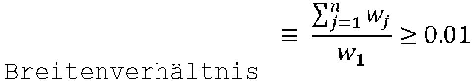 wobei "n" die Anzahl der länglichen Dehnungsfugen (50) an der mindestens einen Seitenwand (16) ist, wobei jede der länglichen Dehnungsfugen eine horizontale Breite (wj) aufweist, und wobei die gesamte horizontale Breitenabmessung (w1) der ersten Fläche (22) der ersten Schicht (20) an der mindestens einen Seitenwand (16) am Schnittpunkt der ersten Fläche (22) mit einer Bodenfläche (11) des metallurgischen Behältnisses gemessen wird.
 - Feuerfeste Auskleidungsstruktur (18) nach Anspruch 1, wobei das erste feuerfeste Material und das zweite feuerfeste Material unabhängig aus der Gruppe ausgewählt sind, die aus feuerfesten Aluminiumoxid-Materialien, feuerfesten Magnesiumoxid-Materialien, feuerfesten Chrommaterialien und feuerfesten Zirkoniumoxid-Materialien sowie Kombinationen daraus besteht.
- Feuerfeste Auskleidungsstruktur (18) nach Anspruch 1, wobei die mindestens eine längliche Dehnungsfuge (50) eine längliche Kontur umfasst, die aus der Gruppe ausgewählt ist, die aus vertikalen Linien, diagonalen Linien, Polylinien, Kurven und Kombinationen daraus besteht.
- Feuerfeste Auskleidungsstruktur (18) nach Anspruch 1, wobei die Breitenabmessung der mindestens einen länglichen Dehnungsfuge (50) im Bereich von 1 Millimeter (0,04 Inch) bis 100 Millimeter (4 Inch) liegt.
- Feuerfeste Auskleidungsstruktur (18) nach Anspruch 1, wobei die mindestens eine längliche Dehnungsfuge (50) eine Tiefenabmessung aufweist, die sich von der ersten Fläche der ersten Schicht (22) in Richtung der zweiten Fläche der ersten Schicht (24) erstreckt, und wobei die Tiefenabmessung mindestens 50 % der Dicke der ersten Schicht (20) beträgt.
- Feuerfeste Auskleidungsstruktur (18) nach Anspruch 1, wobei die Tiefenabmessung der mindestens einen länglichen Dehnungsfuge (50) 100 % der Dicke der ersten Schicht (20) beträgt, wobei sich die Tiefenabmessung der mindestens einen länglichen Dehnungsfuge von der ersten Fläche der ersten Schicht (22) bis zur zweiten Fläche der ersten Schicht (24) erstreckt, und wobei die erste Fläche der zweiten Schicht (22) durch die mindestens eine längliche Dehnungsfuge (50) teilweise freigelegt ist.
- Feuerfeste Auskleidungsstruktur (18) nach Anspruch 1, wobei die Dicke der ersten Schicht (20) und die Dicke der zweiten Schicht (30) unabhängig im Bereich von 1 Millimeter (0,04 Inch) bis 65 Millimeter (2,6 Inch) liegen.
- Feuerfeste Auskleidungsstruktur (18) nach Anspruch 1, wobei die mindestens eine längliche Dehnungsfuge (50) eine vertikale Höhenabmessung aufweist, die mindestens 75 % der vertikalen Höhenabmessung der ersten Fläche der ersten Schicht (22) beträgt.
- Feuerfeste Auskleidungsstruktur (18) nach Anspruch 1, die mehrere längliche Dehnungsfugen (50) umfasst, die in der ersten Fläche der ersten Schicht (22) ausgebildet sind, wobei sich jede der mehreren länglichen Dehnungsfugen durch die erste Fläche der ersten Schicht (22) in einer im Wesentlichen vertikalen Richtung erstreckt, und wobei die mehreren länglichen Dehnungsfugen (50) in einer horizontalen Richtung um mindestens 2,54 Zentimeter (1 Inch) voneinander beabstandet sind.
- Feuerfeste Auskleidungsstruktur (18) nach Anspruch 1, die des Weiteren eine längliche Dehnungsfuge (50) umfasst, die in der ersten Fläche der ersten Schicht (22) ausgebildet ist und sich in einer im Wesentlichen horizontalen Richtung durch die erste Fläche der ersten Schicht (22) hindurch erstreckt.
- Feuerfeste Auskleidungsstruktur (18) nach Anspruch 1, die des Weiteren eine dritte Schicht (40) umfasst, die unter mindestens einem Abschnitt der zweiten Schicht (30) liegt, wobei die dritte Schicht (40) eine erste Fläche (42) aufweist, die von der Seitenwand (16) des metallurgischen Behältnisses fort weist, und eine zweite Fläche (44) aufweist, die der ersten Fläche (42) gegenüberliegt und der Seitenwand (16) des metallurgischen Behältnisses zugewandt ist und mit ihr in Kontakt steht, wobei die dritte Schicht (40) ein drittes feuerfestes Material umfasst, wobei die zweite Fläche der zweiten Schicht mit der ersten Fläche der dritten Schicht in Kontakt steht.
- Metallurgisches Behältnis, das umfasst:einen Boden (11) und eine Seitenwand (16), die sich von dem Boden aus in einer im Wesentlichen vertikalen Richtung erstreckt; unddie feuerfeste Auskleidungsstruktur (18) nach Anspruch 1, die auf mindestens einem Abschnitt der Seitenwand (16) des metallurgischen Behältnisses angeordnet ist.
- Metallurgisches Behältnis nach Anspruch 12, wobei das metallurgische Behältnis eine Zwischenpfanne (10) umfasst, die für einen Stranggussvorgang konfiguriert ist, wobei die Zwischenpfanne mindestens vier sich überschneidende Seitenwände (16) umfasst, wobei die feuerfeste Auskleidungsstruktur auf mindestens einem Abschnitt der mindestens vier Seitenwände angeordnet ist, und wobei mindestens eine längliche Dehnungsfuge (50) in der ersten Fläche der ersten Schicht (22) an jeder der mindestens vier Seitenwände ausgebildet ist, und wobei sich die länglichen Dehnungsfugen durch die ersten Flächen der ersten Schichten (22) in einer im Wesentlichen vertikalen Richtung erstrecken.
Priority Applications (1)
| Application Number | Priority Date | Filing Date | Title |
|---|---|---|---|
| RS20221014A RS63720B1 (sr) | 2017-08-29 | 2018-08-21 | Struktura vatrostalne obloge |
Applications Claiming Priority (2)
| Application Number | Priority Date | Filing Date | Title |
|---|---|---|---|
| US201762551509P | 2017-08-29 | 2017-08-29 | |
| PCT/US2018/047253 WO2019046042A1 (en) | 2017-08-29 | 2018-08-21 | REFRACTORY COATING STRUCTURE |
Publications (3)
| Publication Number | Publication Date |
|---|---|
| EP3676034A1 EP3676034A1 (de) | 2020-07-08 |
| EP3676034A4 EP3676034A4 (de) | 2021-04-21 |
| EP3676034B1 true EP3676034B1 (de) | 2022-08-10 |
Family
ID=65527771
Family Applications (1)
| Application Number | Title | Priority Date | Filing Date |
|---|---|---|---|
| EP18849678.0A Active EP3676034B1 (de) | 2017-08-29 | 2018-08-21 | Feuerfeste auskleidungsstruktur |
Country Status (21)
| Country | Link |
|---|---|
| US (1) | US11440089B2 (de) |
| EP (1) | EP3676034B1 (de) |
| JP (1) | JP7187541B2 (de) |
| KR (1) | KR102545964B1 (de) |
| CN (2) | CN109465434B (de) |
| AR (1) | AR112883A1 (de) |
| AU (1) | AU2018324469B2 (de) |
| BR (1) | BR112020003764B1 (de) |
| CA (1) | CA3069751A1 (de) |
| DK (1) | DK3676034T3 (de) |
| EA (1) | EA202090334A1 (de) |
| ES (1) | ES2930082T3 (de) |
| HU (1) | HUE060308T2 (de) |
| MX (1) | MX2020002333A (de) |
| PH (1) | PH12020500136A1 (de) |
| PL (1) | PL3676034T3 (de) |
| PT (1) | PT3676034T (de) |
| RS (1) | RS63720B1 (de) |
| TW (1) | TWI837098B (de) |
| WO (1) | WO2019046042A1 (de) |
| ZA (1) | ZA202000435B (de) |
Families Citing this family (2)
| Publication number | Priority date | Publication date | Assignee | Title |
|---|---|---|---|---|
| TWI837098B (zh) * | 2017-08-29 | 2024-04-01 | 美商維蘇威美國公司 | 耐火襯裡結構及冶金容器 |
| CN110817138B (zh) * | 2019-09-05 | 2021-10-26 | 首钢集团有限公司 | 一种耐火圆筒容器 |
Family Cites Families (19)
| Publication number | Priority date | Publication date | Assignee | Title |
|---|---|---|---|---|
| AT288952B (de) * | 1968-12-06 | 1971-03-25 | Veitscher Magnesitwerke Ag | Feuerfeste Auskleidung mit Dehnungsausgleich und Verfahren zur Herstellung einer Isoliermasse für solche Auskleidungen |
| JPS4816684B1 (de) * | 1969-06-11 | 1973-05-24 | ||
| GB1469513A (en) * | 1973-07-30 | 1977-04-06 | Foseco Trading Ag | Tundishes |
| US4196159A (en) * | 1973-03-07 | 1980-04-01 | Eisenwerk-Gesellschaft Maximilianshutte Mbh. | Process for increasing the life of the refractory masonry of metallurgical vessels |
| JPS51122122U (de) * | 1975-03-29 | 1976-10-04 | ||
| GB1585180A (en) * | 1976-10-07 | 1981-02-25 | Foseco Trading Ag | Lining slabs for containers for molten metal |
| US4194730A (en) * | 1977-12-27 | 1980-03-25 | Foseco Trading Ag | Molten metal handling vessels |
| FR2451789A1 (fr) * | 1979-03-22 | 1980-10-17 | Daussan & Co | Revetement thermiquement isolant pour recipients metallurgiques et procede s'y rapportant |
| US4441700A (en) * | 1981-05-07 | 1984-04-10 | Labate M D | Blast furnace trough and liner combination |
| KR900009216B1 (ko) * | 1986-11-27 | 1990-12-24 | 다우상 에 콤파그네 | 야금용 용기 내부 보호 라이닝 및 그 성형방법 |
| TW265327B (de) * | 1990-05-14 | 1995-12-11 | Minteq Internat Inc | |
| GB9018205D0 (en) | 1990-08-18 | 1990-10-03 | Foseco Int | Lining of metallurgical vessels |
| US6864199B2 (en) | 2003-02-07 | 2005-03-08 | Allied Mineral Products, Inc. | Crack-resistant dry refractory |
| US8119077B2 (en) * | 2009-01-07 | 2012-02-21 | General Electric Company | Control joints in refractory lining systems and methods |
| CN202791146U (zh) | 2012-08-10 | 2013-03-13 | 山东百斯达化工有限公司 | 一种内衬耐火材料碳钢热风管道 |
| DE102013020732C9 (de) * | 2013-12-10 | 2020-08-06 | Refratechnik Holding Gmbh | Verwendung eines grobkeramischen, feuerfesten Erzeugnisses |
| KR101929640B1 (ko) | 2014-01-23 | 2018-12-14 | 제이에프이 스틸 가부시키가이샤 | 용융 금속 용기의 라이닝 구조체의 제조 방법 및 용융 금속 용기의 라이닝 구조체 |
| PL3274111T3 (pl) * | 2015-03-24 | 2020-12-14 | Vesuvius U S A Corporation | Powłoka zbiornika metalurgicznego z zaprojektowaną strukturą perforowaną |
| TWI837098B (zh) | 2017-08-29 | 2024-04-01 | 美商維蘇威美國公司 | 耐火襯裡結構及冶金容器 |
-
2018
- 2018-07-19 TW TW107124982A patent/TWI837098B/zh active
- 2018-08-21 DK DK18849678.0T patent/DK3676034T3/da active
- 2018-08-21 PT PT188496780T patent/PT3676034T/pt unknown
- 2018-08-21 AU AU2018324469A patent/AU2018324469B2/en active Active
- 2018-08-21 ES ES18849678T patent/ES2930082T3/es active Active
- 2018-08-21 RS RS20221014A patent/RS63720B1/sr unknown
- 2018-08-21 BR BR112020003764-8A patent/BR112020003764B1/pt active IP Right Grant
- 2018-08-21 EA EA202090334A patent/EA202090334A1/ru unknown
- 2018-08-21 MX MX2020002333A patent/MX2020002333A/es unknown
- 2018-08-21 US US16/631,669 patent/US11440089B2/en active Active
- 2018-08-21 JP JP2020511991A patent/JP7187541B2/ja active Active
- 2018-08-21 HU HUE18849678A patent/HUE060308T2/hu unknown
- 2018-08-21 KR KR1020207005482A patent/KR102545964B1/ko active IP Right Grant
- 2018-08-21 PL PL18849678.0T patent/PL3676034T3/pl unknown
- 2018-08-21 CA CA3069751A patent/CA3069751A1/en active Pending
- 2018-08-21 EP EP18849678.0A patent/EP3676034B1/de active Active
- 2018-08-21 WO PCT/US2018/047253 patent/WO2019046042A1/en active Search and Examination
- 2018-08-24 CN CN201810970246.XA patent/CN109465434B/zh active Active
- 2018-08-24 CN CN201821368863.4U patent/CN209754004U/zh active Active
- 2018-08-29 AR ARP180102452A patent/AR112883A1/es active IP Right Grant
-
2020
- 2020-01-20 PH PH12020500136A patent/PH12020500136A1/en unknown
- 2020-01-22 ZA ZA2020/00435A patent/ZA202000435B/en unknown
Also Published As
| Publication number | Publication date |
|---|---|
| AU2018324469B2 (en) | 2023-06-29 |
| CN109465434B (zh) | 2022-03-22 |
| US20200198003A1 (en) | 2020-06-25 |
| RS63720B1 (sr) | 2022-11-30 |
| CN109465434A (zh) | 2019-03-15 |
| BR112020003764B1 (pt) | 2023-04-18 |
| JP2020532429A (ja) | 2020-11-12 |
| HUE060308T2 (hu) | 2023-02-28 |
| TWI837098B (zh) | 2024-04-01 |
| KR102545964B1 (ko) | 2023-06-20 |
| AR112883A1 (es) | 2019-12-26 |
| EP3676034A4 (de) | 2021-04-21 |
| WO2019046042A1 (en) | 2019-03-07 |
| ES2930082T3 (es) | 2022-12-07 |
| DK3676034T3 (da) | 2022-11-14 |
| EP3676034A1 (de) | 2020-07-08 |
| CN209754004U (zh) | 2019-12-10 |
| JP7187541B2 (ja) | 2022-12-12 |
| PT3676034T (pt) | 2022-11-15 |
| KR20200046031A (ko) | 2020-05-06 |
| WO2019046042A4 (en) | 2019-05-09 |
| CA3069751A1 (en) | 2019-03-07 |
| PH12020500136A1 (en) | 2020-11-09 |
| AU2018324469A1 (en) | 2020-02-06 |
| EA202090334A1 (ru) | 2020-10-07 |
| BR112020003764A2 (pt) | 2020-09-01 |
| TW201912269A (zh) | 2019-04-01 |
| MX2020002333A (es) | 2020-07-13 |
| US11440089B2 (en) | 2022-09-13 |
| ZA202000435B (en) | 2021-08-25 |
| PL3676034T3 (pl) | 2022-12-05 |
Similar Documents
| Publication | Publication Date | Title |
|---|---|---|
| EP1603850B1 (de) | Rissbeständiger, trockener, feuerfester stoff | |
| EP3676034B1 (de) | Feuerfeste auskleidungsstruktur | |
| GB1469513A (en) | Tundishes | |
| KR102649884B1 (ko) | 내화성 조성물 및 원위치 항산화 배리어층 | |
| US4076224A (en) | Tundishes | |
| JPWO2019046042A5 (de) | ||
| US4900603A (en) | Refractory, heat insulating articles | |
| CA2611360C (en) | Insulating refractory lining | |
| EP3504498B1 (de) | Auskleidung eines metallurgischen gefässes mit geschlossener metallschicht | |
| JPS6343188B2 (de) | ||
| JP4648552B2 (ja) | 耐火物内張およびその築造方法並びにその耐火物内張を備えるrhの槽底 | |
| GB2112374A (en) | Molten metal handling vessels | |
| Sennikov et al. | Serviceability of refractory mixtures for teeming ladle linings | |
| JP2001141372A (ja) | 耐火物ブロック、その製造方法及び溶湯容器 | |
| JP2002003932A (ja) | スリットを有する耐火物浸漬構造体およびその製造方法 |
Legal Events
| Date | Code | Title | Description |
|---|---|---|---|
| STAA | Information on the status of an ep patent application or granted ep patent |
Free format text: STATUS: THE INTERNATIONAL PUBLICATION HAS BEEN MADE |
|
| PUAI | Public reference made under article 153(3) epc to a published international application that has entered the european phase |
Free format text: ORIGINAL CODE: 0009012 |
|
| STAA | Information on the status of an ep patent application or granted ep patent |
Free format text: STATUS: REQUEST FOR EXAMINATION WAS MADE |
|
| 17P | Request for examination filed |
Effective date: 20200330 |
|
| AK | Designated contracting states |
Kind code of ref document: A1 Designated state(s): AL AT BE BG CH CY CZ DE DK EE ES FI FR GB GR HR HU IE IS IT LI LT LU LV MC MK MT NL NO PL PT RO RS SE SI SK SM TR |
|
| AX | Request for extension of the european patent |
Extension state: BA ME |
|
| RIN1 | Information on inventor provided before grant (corrected) |
Inventor name: RICHARDSON, JR., ROBERT L. Inventor name: SCHANER, DANIEL T. Inventor name: MOHANTY, BEDA |
|
| DAV | Request for validation of the european patent (deleted) | ||
| DAX | Request for extension of the european patent (deleted) | ||
| A4 | Supplementary search report drawn up and despatched |
Effective date: 20210322 |
|
| RIC1 | Information provided on ipc code assigned before grant |
Ipc: B22D 41/00 20060101AFI20210316BHEP Ipc: B22D 41/02 20060101ALI20210316BHEP Ipc: F27D 1/00 20060101ALI20210316BHEP Ipc: F27D 1/10 20060101ALI20210316BHEP |
|
| GRAP | Despatch of communication of intention to grant a patent |
Free format text: ORIGINAL CODE: EPIDOSNIGR1 |
|
| STAA | Information on the status of an ep patent application or granted ep patent |
Free format text: STATUS: GRANT OF PATENT IS INTENDED |
|
| RIC1 | Information provided on ipc code assigned before grant |
Ipc: F27D 1/10 20060101ALI20220202BHEP Ipc: F27D 1/00 20060101ALI20220202BHEP Ipc: B22D 41/02 20060101ALI20220202BHEP Ipc: B22D 41/00 20060101AFI20220202BHEP |
|
| INTG | Intention to grant announced |
Effective date: 20220309 |
|
| GRAS | Grant fee paid |
Free format text: ORIGINAL CODE: EPIDOSNIGR3 |
|
| GRAA | (expected) grant |
Free format text: ORIGINAL CODE: 0009210 |
|
| STAA | Information on the status of an ep patent application or granted ep patent |
Free format text: STATUS: THE PATENT HAS BEEN GRANTED |
|
| AK | Designated contracting states |
Kind code of ref document: B1 Designated state(s): AL AT BE BG CH CY CZ DE DK EE ES FI FR GB GR HR HU IE IS IT LI LT LU LV MC MK MT NL NO PL PT RO RS SE SI SK SM TR |
|
| REG | Reference to a national code |
Ref country code: AT Ref legal event code: REF Ref document number: 1510115 Country of ref document: AT Kind code of ref document: T Effective date: 20220815 Ref country code: CH Ref legal event code: EP |
|
| REG | Reference to a national code |
Ref country code: IE Ref legal event code: FG4D |
|
| REG | Reference to a national code |
Ref country code: DE Ref legal event code: R096 Ref document number: 602018039227 Country of ref document: DE |
|
| REG | Reference to a national code |
Ref country code: RO Ref legal event code: EPE |
|
| REG | Reference to a national code |
Ref country code: DK Ref legal event code: T3 Effective date: 20221107 |
|
| REG | Reference to a national code |
Ref country code: PT Ref legal event code: SC4A Ref document number: 3676034 Country of ref document: PT Date of ref document: 20221115 Kind code of ref document: T Free format text: AVAILABILITY OF NATIONAL TRANSLATION Effective date: 20221108 Ref country code: SE Ref legal event code: TRGR |
|
| REG | Reference to a national code |
Ref country code: NL Ref legal event code: FP |
|
| REG | Reference to a national code |
Ref country code: ES Ref legal event code: FG2A Ref document number: 2930082 Country of ref document: ES Kind code of ref document: T3 Effective date: 20221207 |
|
| REG | Reference to a national code |
Ref country code: NO Ref legal event code: T2 Effective date: 20220810 |
|
| REG | Reference to a national code |
Ref country code: LT Ref legal event code: MG9D |
|
| REG | Reference to a national code |
Ref country code: GR Ref legal event code: EP Ref document number: 20220402190 Country of ref document: GR Effective date: 20221212 |
|
| REG | Reference to a national code |
Ref country code: SK Ref legal event code: T3 Ref document number: E 40796 Country of ref document: SK |
|
| PG25 | Lapsed in a contracting state [announced via postgrant information from national office to epo] |
Ref country code: LV Free format text: LAPSE BECAUSE OF FAILURE TO SUBMIT A TRANSLATION OF THE DESCRIPTION OR TO PAY THE FEE WITHIN THE PRESCRIBED TIME-LIMIT Effective date: 20220810 Ref country code: LT Free format text: LAPSE BECAUSE OF FAILURE TO SUBMIT A TRANSLATION OF THE DESCRIPTION OR TO PAY THE FEE WITHIN THE PRESCRIBED TIME-LIMIT Effective date: 20220810 |
|
| PG25 | Lapsed in a contracting state [announced via postgrant information from national office to epo] |
Ref country code: IS Free format text: LAPSE BECAUSE OF FAILURE TO SUBMIT A TRANSLATION OF THE DESCRIPTION OR TO PAY THE FEE WITHIN THE PRESCRIBED TIME-LIMIT Effective date: 20221210 Ref country code: HR Free format text: LAPSE BECAUSE OF FAILURE TO SUBMIT A TRANSLATION OF THE DESCRIPTION OR TO PAY THE FEE WITHIN THE PRESCRIBED TIME-LIMIT Effective date: 20220810 |
|
| REG | Reference to a national code |
Ref country code: HU Ref legal event code: AG4A Ref document number: E060308 Country of ref document: HU |
|
| PG25 | Lapsed in a contracting state [announced via postgrant information from national office to epo] |
Ref country code: SM Free format text: LAPSE BECAUSE OF FAILURE TO SUBMIT A TRANSLATION OF THE DESCRIPTION OR TO PAY THE FEE WITHIN THE PRESCRIBED TIME-LIMIT Effective date: 20220810 |
|
| REG | Reference to a national code |
Ref country code: DE Ref legal event code: R097 Ref document number: 602018039227 Country of ref document: DE |
|
| PG25 | Lapsed in a contracting state [announced via postgrant information from national office to epo] |
Ref country code: MC Free format text: LAPSE BECAUSE OF FAILURE TO SUBMIT A TRANSLATION OF THE DESCRIPTION OR TO PAY THE FEE WITHIN THE PRESCRIBED TIME-LIMIT Effective date: 20220810 Ref country code: EE Free format text: LAPSE BECAUSE OF FAILURE TO SUBMIT A TRANSLATION OF THE DESCRIPTION OR TO PAY THE FEE WITHIN THE PRESCRIBED TIME-LIMIT Effective date: 20220810 |
|
| PLBE | No opposition filed within time limit |
Free format text: ORIGINAL CODE: 0009261 |
|
| STAA | Information on the status of an ep patent application or granted ep patent |
Free format text: STATUS: NO OPPOSITION FILED WITHIN TIME LIMIT |
|
| PG25 | Lapsed in a contracting state [announced via postgrant information from national office to epo] |
Ref country code: AL Free format text: LAPSE BECAUSE OF FAILURE TO SUBMIT A TRANSLATION OF THE DESCRIPTION OR TO PAY THE FEE WITHIN THE PRESCRIBED TIME-LIMIT Effective date: 20220810 |
|
| P01 | Opt-out of the competence of the unified patent court (upc) registered |
Effective date: 20230526 |
|
| 26N | No opposition filed |
Effective date: 20230511 |
|
| PG25 | Lapsed in a contracting state [announced via postgrant information from national office to epo] |
Ref country code: IE Free format text: LAPSE BECAUSE OF NON-PAYMENT OF DUE FEES Effective date: 20220821 |
|
| REG | Reference to a national code |
Ref country code: AT Ref legal event code: UEP Ref document number: 1510115 Country of ref document: AT Kind code of ref document: T Effective date: 20220810 |
|
| PGFP | Annual fee paid to national office [announced via postgrant information from national office to epo] |
Ref country code: NL Payment date: 20230826 Year of fee payment: 6 |
|
| PGFP | Annual fee paid to national office [announced via postgrant information from national office to epo] |
Ref country code: TR Payment date: 20230808 Year of fee payment: 6 Ref country code: RO Payment date: 20230803 Year of fee payment: 6 Ref country code: NO Payment date: 20230829 Year of fee payment: 6 Ref country code: IT Payment date: 20230822 Year of fee payment: 6 Ref country code: GB Payment date: 20230828 Year of fee payment: 6 Ref country code: FI Payment date: 20230825 Year of fee payment: 6 Ref country code: ES Payment date: 20230901 Year of fee payment: 6 Ref country code: CZ Payment date: 20230810 Year of fee payment: 6 Ref country code: CH Payment date: 20230903 Year of fee payment: 6 Ref country code: AT Payment date: 20230802 Year of fee payment: 6 |
|
| PGFP | Annual fee paid to national office [announced via postgrant information from national office to epo] |
Ref country code: SK Payment date: 20230801 Year of fee payment: 6 Ref country code: SI Payment date: 20230802 Year of fee payment: 6 Ref country code: SE Payment date: 20230827 Year of fee payment: 6 Ref country code: RS Payment date: 20230807 Year of fee payment: 6 Ref country code: PT Payment date: 20230802 Year of fee payment: 6 Ref country code: PL Payment date: 20230807 Year of fee payment: 6 Ref country code: HU Payment date: 20230809 Year of fee payment: 6 Ref country code: GR Payment date: 20230829 Year of fee payment: 6 Ref country code: FR Payment date: 20230825 Year of fee payment: 6 Ref country code: DK Payment date: 20230829 Year of fee payment: 6 Ref country code: DE Payment date: 20230829 Year of fee payment: 6 Ref country code: BE Payment date: 20230828 Year of fee payment: 6 |
|
| PG25 | Lapsed in a contracting state [announced via postgrant information from national office to epo] |
Ref country code: CY Free format text: LAPSE BECAUSE OF FAILURE TO SUBMIT A TRANSLATION OF THE DESCRIPTION OR TO PAY THE FEE WITHIN THE PRESCRIBED TIME-LIMIT Effective date: 20220810 |
|
| PG25 | Lapsed in a contracting state [announced via postgrant information from national office to epo] |
Ref country code: MK Free format text: LAPSE BECAUSE OF FAILURE TO SUBMIT A TRANSLATION OF THE DESCRIPTION OR TO PAY THE FEE WITHIN THE PRESCRIBED TIME-LIMIT Effective date: 20220810 |
|
| PG25 | Lapsed in a contracting state [announced via postgrant information from national office to epo] |
Ref country code: BG Free format text: LAPSE BECAUSE OF FAILURE TO SUBMIT A TRANSLATION OF THE DESCRIPTION OR TO PAY THE FEE WITHIN THE PRESCRIBED TIME-LIMIT Effective date: 20220810 |
|
| PGFP | Annual fee paid to national office [announced via postgrant information from national office to epo] |
Ref country code: LU Payment date: 20240827 Year of fee payment: 7 |