EP3674596A1 - Vorrichtung zum gewichtsausgleich für eine bessere fixierung einer stirnlampe auf dem kopf - Google Patents
Vorrichtung zum gewichtsausgleich für eine bessere fixierung einer stirnlampe auf dem kopf Download PDFInfo
- Publication number
- EP3674596A1 EP3674596A1 EP19219943.8A EP19219943A EP3674596A1 EP 3674596 A1 EP3674596 A1 EP 3674596A1 EP 19219943 A EP19219943 A EP 19219943A EP 3674596 A1 EP3674596 A1 EP 3674596A1
- Authority
- EP
- European Patent Office
- Prior art keywords
- rigid
- strip
- semi
- strands
- point
- Prior art date
- Legal status (The legal status is an assumption and is not a legal conclusion. Google has not performed a legal analysis and makes no representation as to the accuracy of the status listed.)
- Granted
Links
Images


Classifications
-
- F—MECHANICAL ENGINEERING; LIGHTING; HEATING; WEAPONS; BLASTING
- F21—LIGHTING
- F21L—LIGHTING DEVICES OR SYSTEMS THEREOF, BEING PORTABLE OR SPECIALLY ADAPTED FOR TRANSPORTATION
- F21L4/00—Electric lighting devices with self-contained electric batteries or cells
-
- F—MECHANICAL ENGINEERING; LIGHTING; HEATING; WEAPONS; BLASTING
- F21—LIGHTING
- F21V—FUNCTIONAL FEATURES OR DETAILS OF LIGHTING DEVICES OR SYSTEMS THEREOF; STRUCTURAL COMBINATIONS OF LIGHTING DEVICES WITH OTHER ARTICLES, NOT OTHERWISE PROVIDED FOR
- F21V21/00—Supporting, suspending, or attaching arrangements for lighting devices; Hand grips
- F21V21/14—Adjustable mountings
- F21V21/30—Pivoted housings or frames
-
- F—MECHANICAL ENGINEERING; LIGHTING; HEATING; WEAPONS; BLASTING
- F21—LIGHTING
- F21L—LIGHTING DEVICES OR SYSTEMS THEREOF, BEING PORTABLE OR SPECIALLY ADAPTED FOR TRANSPORTATION
- F21L4/00—Electric lighting devices with self-contained electric batteries or cells
- F21L4/005—Electric lighting devices with self-contained electric batteries or cells the device being a pocket lamp
-
- A—HUMAN NECESSITIES
- A42—HEADWEAR
- A42B—HATS; HEAD COVERINGS
- A42B1/00—Hats; Caps; Hoods
- A42B1/24—Hats; Caps; Hoods with means for attaching articles thereto, e.g. memorandum tablets or mirrors
- A42B1/242—Means for mounting detecting, signalling or lighting devices
- A42B1/244—Means for mounting lamps
-
- F—MECHANICAL ENGINEERING; LIGHTING; HEATING; WEAPONS; BLASTING
- F21—LIGHTING
- F21V—FUNCTIONAL FEATURES OR DETAILS OF LIGHTING DEVICES OR SYSTEMS THEREOF; STRUCTURAL COMBINATIONS OF LIGHTING DEVICES WITH OTHER ARTICLES, NOT OTHERWISE PROVIDED FOR
- F21V21/00—Supporting, suspending, or attaching arrangements for lighting devices; Hand grips
- F21V21/08—Devices for easy attachment to any desired place, e.g. clip, clamp, magnet
- F21V21/084—Head fittings
-
- F—MECHANICAL ENGINEERING; LIGHTING; HEATING; WEAPONS; BLASTING
- F21—LIGHTING
- F21V—FUNCTIONAL FEATURES OR DETAILS OF LIGHTING DEVICES OR SYSTEMS THEREOF; STRUCTURAL COMBINATIONS OF LIGHTING DEVICES WITH OTHER ARTICLES, NOT OTHERWISE PROVIDED FOR
- F21V21/00—Supporting, suspending, or attaching arrangements for lighting devices; Hand grips
- F21V21/14—Adjustable mountings
- F21V21/145—Adjustable mountings for portable lighting devices
-
- F—MECHANICAL ENGINEERING; LIGHTING; HEATING; WEAPONS; BLASTING
- F21—LIGHTING
- F21V—FUNCTIONAL FEATURES OR DETAILS OF LIGHTING DEVICES OR SYSTEMS THEREOF; STRUCTURAL COMBINATIONS OF LIGHTING DEVICES WITH OTHER ARTICLES, NOT OTHERWISE PROVIDED FOR
- F21V23/00—Arrangement of electric circuit elements in or on lighting devices
-
- A—HUMAN NECESSITIES
- A42—HEADWEAR
- A42B—HATS; HEAD COVERINGS
- A42B3/00—Helmets; Helmet covers ; Other protective head coverings
- A42B3/04—Parts, details or accessories of helmets
- A42B3/10—Linings
- A42B3/14—Suspension devices
- A42B3/142—Suspension devices with restraining or stabilizing means, e.g. nape straps
Definitions
- the present invention relates to headlamps and in particular a device for holding a headlamp strip.
- Headlamps originally used in coal mines, have been very successful in the leisure sector, particularly speleology and hiking. They also figure prominently in the range of professional tools.
- the most recent headlamps have a high-power light source, located at the front, and a heavy-duty battery pack which is located at the rear.
- the figure 1 illustrates a first type of known headband, marketed by the applicant company, making it possible to ensure the attachment to the head of a user of a headlamp provided with a fairly large battery, fixed to the belt.
- the figure 2 illustrates a second example of a fairly bulky fastening device comprising several fixing bands, as described in the patent application EP2462825 , allowing the attachment of a protective helmet or welding mask on the head of a user.
- the figure 3 illustrates another example of a fastening system, as described in the patent FR3047570 allowing the fixing of glasses
- the present invention aims to provide a headlamp with a new type of rigid / semi-rigid headband allowing wide possibilities of adjustment on various heads of users.
- Another object of the present invention to provide a headlamp with a light support band and with a load balancing system between the weight of the lamp and that - more importantly - of the battery pack .
- the fastening elements are removable, for example by clipping.
- the first ends (A, A ') of the first and second strands are fixed via a sliding element making it possible to vary the position of the points A and A' on the strip.
- the second ends (B, B ') of the first and second strands are merged at the same point located close to the battery at the rear of the strip.
- the strip is of constant length, symmetrical with respect to a median sagittal plane, and comprises an alternation of rigid / semi-rigid elements to allow deformation in space and adjustment to the head of a user. .
- the invention is particularly suitable for producing a compact lamp comprising the light module and a relatively heavy power source.
- the load balancing device which will be described below is perfectly suited to the production of a headlamp comprising a rigid / semi-rigid retaining strip offering a structure that is particularly easy to adjust, allowing perfect retention of the lamp even when it has, in particular, a particularly heavy battery at the rear. It should be noted that the device could also be advantageous in the case of a remote battery to allow load balancing when the strip supports a particularly heavy headlamp which would tend to destabilize the headlamp forwards. Consequently, the embodiments which will be described below provide a significant solution for rebalancing the loads which would appear either at the front or at the rear of the retaining strip.
- the balancing device described below proves to be usable for any type of headlamp, and any type of headband, elastic or not, the device will be more specifically described in relation to a specific headlamp, such as described in the European patent application EP3290785 , entitled “ Headlamp with a rigid or semi / rigid headband ", filed on August 28, 2017 by the applicant of this patent application, which allows the realization of a light headlamp, well balanced and perfectly aesthetic.
- This new type of headlamp has a rigid / semi-rigid headband that makes a “break” with conventional headbands, bringing a new aesthetic but also new functionalities for almost immediate adjustment of the headband on the head of a user.
- This headlamp uses for this purpose a specific headband presenting a combination of rigid / semi-rigid structures of constant length and belonging to a family of shapes three-dimensional likely to deform in space, in several planes.
- This strip allows it to maintain a constant length, while allowing deformations along the three planes, which allows the strip to match the shape of the head of a user.
- the front part 21, the side parts 24 and 22, and the rear part 23 which are all semi-rigid, allow the deformation of the strip at constant length in the three planes (x, y), (x, z) and (y , z), thus causing the variability of the rays of curves R1, R2 and R3 allowing the fixing of the strip 10 on a head of any dimension.
- the figure 4b illustrates the positioning of the headband on the head of a user, without the lamp supply battery, while the figure 4c shows the strip with a supply battery 38 at the rear, as well as a device 39 for fixing the tightening elastic.
- the figure 4d illustrates a front perspective of the same banner illustrated in the figures 4a-4c , where we can clearly see the lamp 40 located at the front and the battery 38 in the rear position.
- FIGS. 5a and 5b show more specifically the detail of a first simplified embodiment of a strip 50 comprising an alternation of deformable semi-rigid elements (in dark) and rigid elements (in light), allowing the deformation of the strip at constant length in the three planes (x, y), (x, z) and (y, z) and the variability of the angles of curvature R1, R2 and R3, respectively.
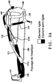
- the figure 5a more specifically shows the left arm of the first embodiment which comprises a semi-rigid front part 100, on which is fixed a rigid part called “plate” serving as support, via a pivot connection, to a lamp 101 comprising one or more LEDs (s) associated with an optical system and a corresponding electronic circuit.
- the front part can be extruded.
- the strip also comprises a rigid rear part 116 (clear) forming a rear part of the strip.
- the element 116 may become semi-rigid to adapt to the xy plane.
- the strip comprises, on its left branch, a first rigid element 111 (of rigidity greater than the semi-rigid element 100) having a first lower end fixed to a first end of the front part 100, as well as a second end upper fixed to a second semi-rigid element 112 (dark, therefore more flexible).
- the rigid element 111 comprises, respectively at its two lower and upper ends, two passage elements 111a and 111b for a first tightening elastic 150.
- the second semi-rigid element 112 has a first end fixed to the second end of the first element 111 and a second end fixed to a first end of a third rigid element 113 serving as a point of passage for the elastic 150 coming from the elements 111b of the left branch.
- the strip then comprises a fourth flexible (semi-rigid) element 114 having a first upper end fixed to a second end of the third element 113 and a second end fixed to a fifth rigid element 115 allowing the fixing of the first elastic 150 from crossing point 111a.
- a fourth flexible (semi-rigid) element 114 having a first upper end fixed to a second end of the third element 113 and a second end fixed to a fifth rigid element 115 allowing the fixing of the first elastic 150 from crossing point 111a.
- the left branch of the strip is finally fixed to a first end of the rigid or semi-rigid strip 116 forming the rear part of the rigid / semi-rigid strip, via a second end of the rigid strip 115.
- the rear part 116 can be rigid or semi-rigid so that the elements 115 and 116 can be manufactured or not.
- the fifth rigid element 115 will be distinct from the latter.
- the elements 115 and 116 may be identical.
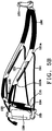
- the figure 5b illustrates the detail of the right branch of the strip which is, as we can see, perfectly symmetrical with respect to the left branch.
- the straight branch comprises a sixth rigid element 121 having a first lower end fixed to a second end of the front part 100 as well as a second upper end fixed to a first end of a seventh flexible element ( semi-rigid) 122.
- the rigid element 121 comprises, respectively at its two lower and upper ends, two passage elements 121a and 121b for a second tightening elastic 151.
- the flexible element 122 has a first end fixed to the element 121 and a second end fixed to an eighth rigid element 123 serving as a point of passage for the elastic 151 coming from the elements 121b of the left branch.
- the strip then comprises a ninth flexible (semi-rigid) element 124 having a first upper end fixed to a second end of the element 123 and a second lower end located at a first end of a tenth rigid element 125 and allowing the fixing of the second elastic 151 coming from the crossing point 121a.
- a ninth flexible (semi-rigid) element 124 having a first upper end fixed to a second end of the element 123 and a second lower end located at a first end of a tenth rigid element 125 and allowing the fixing of the second elastic 151 coming from the crossing point 121a.
- the straight branch of the strip is finally fixed to the rear (semi-rigid) element 116 which forms the rear of the rigid / semi-rigid strip via a second end of the rigid element 125.
- the rigid element 121 has, at its two ends 121a and 121b, the points of passage of the elastic 151 allowing the stress on the radius of curvature R2 and, consequently, the deformation of the strip in the sagittal plane (x, z).
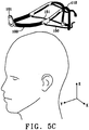
- the figure 5c shows the positioning of the rigid / semi-rigid strip on the head of a user with, highlighted, the role of the elastic bands 150 and 151, making it possible to constrain the deformation of the rigid / semi-rigid strip according to the three planes , reducing the radii of curvature R1-R3 and finally adjusting the tightness of the headband on the head of a user.
- This first embodiment of a rigid / semi-rigid strip illustrated in detail in the figures 5a and 5b proves to be perfectly suited for the production of a light headlamp capable of holding in place a headlamp 101 situated at the front and, at the rear, a battery pack 130, even a large one.
- headlamps are today such that there is a tendency to associate light sources of relatively light LED type - but nevertheless of high brightness - with a relatively heavy supply battery. This is how we notice a difference significant weight between the weight of the lamp 101 present at the front of the strip and that of the battery 130 disposed at the rear.
- the rigid / semi-rigid headband is equipped, as we will now see with the figures 6 and following, of a perfectly specific balancing device which, if it proves to be perfectly suited to the type of rigid / semi-rigid strip may nevertheless be installed on any type of more conventional strip.
- the figure 6 illustrates a top view of a first preferred embodiment of a rigid / semi-rigid strip provided with a load balancing device.
- the device comprises two strands 200 and 300, not extensible, each provided with a first end (resp. 210, 310) and a second end (resp. 220, 320).
- the first end 210 (point A) of the strand 200 is fixed on a front part of the left branch of the strip while the second end 220 (point B) of the strand 200 is fixed to a rear element of the strip.
- the first end 310 (point A ') of the strand 300 is fixed to a front part of the straight branch of the strip while the second end 320 (point B') of the strand 300 is fixed to a rear element of the banner.
- the fixing points A, B, A 'and B' may be permanent or removable, for example by clipping, knot etc ...
- the strip may include a plurality of clip positions enabling the fastening elements to be fixed at several possible locations.
- the two strands are threaded inside an element 400, preferably sliding, making it possible to make a junction C between the two strands 200 and 300.
- the sliding element 400 can be made of any material (plastic , metal, textile) of various shapes (ring, textile).
- the sliding element may consist of two pulleys whose axes are parallel and substantially vertical.
- the figure 7 illustrates the operating principle of the balancing device based on the sliding element 400 which makes it possible to bring the two strands 200 and 300 together at a point C. It will also be observed that the ends B and B 'are close, while the ends A and A 'are relatively distant.
- slightly elastic strands 200 and 300 will be chosen, wide enough to provide comfort for the user, and thin enough not to excessively increase the weight of the strip.
- the sliding element 400 may be made of injected plastic with a shape studied for the comfort of the user, in particular exposing large refined and curved surfaces for optimal contact with the head of the user.
- the sliding element 400 is endowed with a mechanism for tightening the strands 200 and 300, which further accentuates the possibilities of adjusting the strip.
- the ends A, B, A 'and B' are fitted with fixing elements on the rigid / semi-rigid strip respectively 210, 220, 310 and 320 which can be fixed or removable by clipping for example, so that the device balancing based on the sliding element 400 may itself be a removable accessory, useful for certain activities.
- the headlamp can be used in its “refined” form, as shown in the figures 5a and 5b .
- the user wishes to engage in a more “dynamic” activity, such as running, for example, he will find an appreciable advantage in the installation of the balancing device based on the two strands 200 and 300 and the sliding element 400.
- the attachment points will be positioned on rigid elements making up the rigid / semi-rigid strip. Alternatively, they can be positioned on more flexible elements.
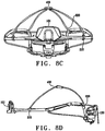
- FIGS. 8a, 8b , 8c, 8d and 8th illustrate several perspective views of a second embodiment of a more sophisticated rigid / semi-rigid strip, comprising fixing points A and A ′ fixed respectively to the front part, while the two rear fixing points B and B 'are arranged on the elements 113 and 123 of the left and right branches of the strip.
- the fixing points are produced by means of clips which are configured to be able to be placed in one or more notches arranged on the sides of the strip so as to allow adjustable fixing.
- the attachment points can also be produced by means of slides allowing lateral movement of the attachment points on each side of the headlamp retaining strip.
- the figure 9 illustrates how to obtain, as the sliding element 400 slides (point C), various possibilities for adjusting the strip on the user's head.
- the strands 200 and 300 gradually come to conform to the shape of the head. The efforts are thus distributed in good part on the top of the head, increasing the comfort and the stability of the headlamp.
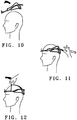
- the figures 10, 11 and 12 illustrate the way in which a user can, thanks to the advantageous arrangement of the invention, position the headlamp on his head and cause the adjustment of the strip by manipulating the sliding element 400 with one hand.
- the figure 13 illustrates a third embodiment in which the attachment points B and B ′ are made to coincide on the battery 130, when the latter is arranged at the rear of the headlamp.
- this arrangement can be provided even in the absence of a battery at the rear, when the headlamp comprises, for example, a remote battery.
- the attachment points may advantageously be fixed to rear attachment points of the strip.
- the load balancing device has an attachment point at the rear which is based on the "tanka" usually used for adjusting the strip.
- the sliding element 400 can be replaced by a seam, as in the example of Figures 16a and 16b , and it is the same "tanka" which is used for the adjustment of the strip which also allows the adjustment of the load balancing device.
- the figure 15a to 15c illustrate three different variants of the sliding element 400.
- the figure 15a recalls the preferred form of the sliding element 400 which is the form used in the embodiments which have been described in relation to the preceding figures.
- the figure 15b illustrates a second variant in which the sliding element 500 comprises two independent slides, respectively based on two parts 510 and 520, respectively left and right, into which each of the two strands 200 and 300 would be threaded.
- Each of the parts 510 and 520 could thus slide along the two strands, in order to reveal two junction points C and C '.
- Such an arrangement proves to be particularly advantageous when the rear attachment points are particularly distant, as illustrated in the second embodiment of the figures 8a-8e , since it becomes possible to adjust the device by independently sliding each of the parts 510 and 520. With thus a double possibility of adjustment, at the front and at the rear, with a "triangle opening" both at front and back.
- the double slide formed by the parts 510 and 520 is made of deformable plastic material, which makes it possible to obtain two slides deformable under the tension of the strands 200 and 300, which could thus facilitate the tightening of the device. load distribution by simple friction or friction on the deformable parts 510 and 520.
- the slide element comprises three distinct non-deformable parts, namely a left element 610, a central element 620 and a right element 630, making it possible to cause significant changes in direction of each of the two strands 800 and 900 used to connect the points of 'fasteners A, A', B and B 'on the retaining strip. So we get thanks in this configuration a crossing of the links and a fairly significant friction allowing the tightening of the device on the skull of the user.
- FIGS 16a and 16b illustrate a fifth embodiment of a load balancing device, in which there is, instead of the slide 400 present on the two strands 200 and 300 - only the strand 200 being shown in the figure 16b - a seam 1010 to connect the two strands 200 and 300 at a fixed point C.
- the attachment point A is embodied, in this embodiment, by a textile placed on the retaining strip comprising a loop 1020 in which comes s 'thread the strand 200 and then go to join a fixation on a sliding element 1030 positioned on the strip. Thanks to this configuration, a simple and nevertheless effective adjustment possibility is thus obtained.
Landscapes
- Engineering & Computer Science (AREA)
- General Engineering & Computer Science (AREA)
- Helmets And Other Head Coverings (AREA)
- Non-Portable Lighting Devices Or Systems Thereof (AREA)
- Arrangement Of Elements, Cooling, Sealing, Or The Like Of Lighting Devices (AREA)
Applications Claiming Priority (1)
| Application Number | Priority Date | Filing Date | Title |
|---|---|---|---|
| FR1874422A FR3091328A1 (fr) | 2018-12-31 | 2018-12-31 | Dispositif d’équilibrage améliorant le maintien sur la tête d’une lampe frontale |
Publications (2)
| Publication Number | Publication Date |
|---|---|
| EP3674596A1 true EP3674596A1 (de) | 2020-07-01 |
| EP3674596B1 EP3674596B1 (de) | 2021-09-01 |
Family
ID=67514707
Family Applications (1)
| Application Number | Title | Priority Date | Filing Date |
|---|---|---|---|
| EP19219943.8A Active EP3674596B1 (de) | 2018-12-31 | 2019-12-28 | Ausgleichsvorrichtung zur verbesserung des haltens auf dem kopf einer stirnlampe |
Country Status (5)
| Country | Link |
|---|---|
| US (1) | US11268681B2 (de) |
| EP (1) | EP3674596B1 (de) |
| CN (1) | CN111473257B (de) |
| ES (1) | ES2899589T3 (de) |
| FR (1) | FR3091328A1 (de) |
Cited By (1)
| Publication number | Priority date | Publication date | Assignee | Title |
|---|---|---|---|---|
| EP4047261A1 (de) * | 2021-02-23 | 2022-08-24 | Zedel | Stirnband für stirnlampe |
Families Citing this family (8)
| Publication number | Priority date | Publication date | Assignee | Title |
|---|---|---|---|---|
| US11969046B2 (en) * | 2018-06-27 | 2024-04-30 | Stryker Corporation | Protective apparel system with a lens assembly |
| USD936878S1 (en) * | 2019-05-29 | 2021-11-23 | Energizer Brands, Llc | Lighting device |
| USD1010891S1 (en) * | 2019-07-25 | 2024-01-09 | Zedel | Headlamp |
| USD939120S1 (en) | 2019-09-18 | 2021-12-21 | Energizer Brands, Llc | Lighting device |
| USD998201S1 (en) | 2020-10-23 | 2023-09-05 | Energizer Brands, Llc | Lighting device |
| USD1030107S1 (en) | 2021-07-16 | 2024-06-04 | Energizer Brands, Llc | Lighting device |
| USD1072305S1 (en) * | 2022-02-04 | 2025-04-22 | LJE Products | LED safety light for snowmobile helmets |
| USD1116191S1 (en) | 2022-04-29 | 2026-03-03 | Energizer Brands, Llc | Headlamp |
Citations (6)
| Publication number | Priority date | Publication date | Assignee | Title |
|---|---|---|---|---|
| US5115382A (en) * | 1990-09-28 | 1992-05-19 | Smith Robert C | Headlamp apparatus |
| FR2828553A1 (fr) * | 2001-08-07 | 2003-02-14 | Tsl Sport Equipment | Perfectionnement pour lampe frontale ameliorant le confort pour l'utilisateur |
| US7370991B1 (en) * | 2006-12-18 | 2008-05-13 | Ellis-Fant Wanda J | Voice-controlled surgical lighting assembly |
| EP2462825A2 (de) | 2010-12-13 | 2012-06-13 | Otos Wing Co., Ltd. | Kopfband |
| FR3047570A1 (fr) | 2016-02-08 | 2017-08-11 | Joel Jacques Andre Guillot | Dispositif de fixation pour lunettes |
| EP3290785A1 (de) | 2016-08-29 | 2018-03-07 | Zedel | Stirnlampe, die mit einem starren oder halbstarren band versehen ist |
Family Cites Families (21)
| Publication number | Priority date | Publication date | Assignee | Title |
|---|---|---|---|---|
| FR347570A (fr) | 1904-10-31 | 1905-03-15 | Ebenezer Fisher | Pince à tuyaux |
| US2176789A (en) * | 1938-10-19 | 1939-10-17 | Luciano J Capitani | Head lamp |
| DE3426358A1 (de) * | 1984-07-17 | 1986-01-23 | Patent-Treuhand-Gesellschaft für elektrische Glühlampen mbH, 8000 München | Tragbare leuchtvorrichtung |
| FR2569822B1 (fr) * | 1984-08-31 | 1988-08-26 | Colombet Pierre | Lampe electrique frontale |
| US6056413A (en) * | 1997-12-29 | 2000-05-02 | Urso; Charles L. | Cap lamp |
| CN1373969A (zh) * | 1999-07-13 | 2002-10-09 | 瑟吉维森有限公司 | 立体视频观察和图象放大系统 |
| NZ513658A (en) * | 2001-08-20 | 2001-09-28 | Fisher & Paykel Healthcare Ltd | Headgear for nasal masks |
| US20050174753A1 (en) * | 2004-02-06 | 2005-08-11 | Densen Cao | Mining light |
| FR2883359B1 (fr) * | 2005-03-15 | 2007-05-11 | Valeo Vision Sa | Projecteur lumineux pour vehicule automobile, de faible encombrement |
| WO2008091931A1 (en) * | 2007-01-23 | 2008-07-31 | Eveready Battery Company, Inc. | Headlamp with adjustable diffuser lens |
| CN201145149Y (zh) * | 2007-09-11 | 2008-11-05 | 吴建军 | 带警示灯的照明灯 |
| GB0722592D0 (en) * | 2007-11-16 | 2007-12-27 | Birmingham City University | Surgeons headgear |
| US8075154B2 (en) * | 2008-03-07 | 2011-12-13 | Alpha-Med Surge | Headlight with directed flow heat sink |
| TWI585990B (zh) | 2011-08-26 | 2017-06-01 | 行政院原子能委員會核能研究所 | 用於光電元件之基板的剝離結構 |
| CN204345274U (zh) * | 2014-11-25 | 2015-05-20 | 嘉善博兴电子科技有限公司 | 一种自行车led头戴灯 |
| US9885465B2 (en) * | 2015-05-04 | 2018-02-06 | Ultralight Optics, Inc. | Illumination devices |
| CN204943077U (zh) * | 2015-09-08 | 2016-01-06 | 中国人民解放军总医院 | 耳鼻咽喉科专用头灯 |
| CN205065356U (zh) * | 2015-09-17 | 2016-03-02 | 宇堃(天津)科技有限公司 | 新型手术头灯 |
| CN206270877U (zh) * | 2016-08-31 | 2017-06-20 | 深圳小宅科技有限公司 | 一种带电池的头带 |
| CN206890144U (zh) * | 2017-05-22 | 2018-01-16 | 惠州市创舰实业有限公司 | 一种分体式led头灯 |
| CN107477397A (zh) * | 2017-09-01 | 2017-12-15 | 惠州市支持网知识产权运营有限公司 | 医护头灯 |
-
2018
- 2018-12-31 FR FR1874422A patent/FR3091328A1/fr not_active Ceased
-
2019
- 2019-12-28 EP EP19219943.8A patent/EP3674596B1/de active Active
- 2019-12-28 ES ES19219943T patent/ES2899589T3/es active Active
- 2019-12-31 CN CN201911414586.5A patent/CN111473257B/zh active Active
- 2019-12-31 US US16/731,570 patent/US11268681B2/en active Active
Patent Citations (6)
| Publication number | Priority date | Publication date | Assignee | Title |
|---|---|---|---|---|
| US5115382A (en) * | 1990-09-28 | 1992-05-19 | Smith Robert C | Headlamp apparatus |
| FR2828553A1 (fr) * | 2001-08-07 | 2003-02-14 | Tsl Sport Equipment | Perfectionnement pour lampe frontale ameliorant le confort pour l'utilisateur |
| US7370991B1 (en) * | 2006-12-18 | 2008-05-13 | Ellis-Fant Wanda J | Voice-controlled surgical lighting assembly |
| EP2462825A2 (de) | 2010-12-13 | 2012-06-13 | Otos Wing Co., Ltd. | Kopfband |
| FR3047570A1 (fr) | 2016-02-08 | 2017-08-11 | Joel Jacques Andre Guillot | Dispositif de fixation pour lunettes |
| EP3290785A1 (de) | 2016-08-29 | 2018-03-07 | Zedel | Stirnlampe, die mit einem starren oder halbstarren band versehen ist |
Cited By (2)
| Publication number | Priority date | Publication date | Assignee | Title |
|---|---|---|---|---|
| EP4047261A1 (de) * | 2021-02-23 | 2022-08-24 | Zedel | Stirnband für stirnlampe |
| US11585519B2 (en) | 2021-02-23 | 2023-02-21 | Zedel | Headlamp headband |
Also Published As
| Publication number | Publication date |
|---|---|
| CN111473257B (zh) | 2024-05-14 |
| EP3674596B1 (de) | 2021-09-01 |
| US20200208818A1 (en) | 2020-07-02 |
| FR3091328A1 (fr) | 2020-07-03 |
| US11268681B2 (en) | 2022-03-08 |
| CN111473257A (zh) | 2020-07-31 |
| ES2899589T3 (es) | 2022-03-14 |
Similar Documents
| Publication | Publication Date | Title |
|---|---|---|
| EP3674596B1 (de) | Ausgleichsvorrichtung zur verbesserung des haltens auf dem kopf einer stirnlampe | |
| US8444266B2 (en) | Illuminated eyewear | |
| FR2681442A1 (fr) | Nez selle interchangeable pour le montage de verres de lunettes sur une paire de lunettes de soleil. | |
| FR2798721A1 (fr) | Dispositif d'eclairage mains libres integre a un couvre-chef | |
| EP3290785B1 (de) | Stirnlampe, die mit einem starren oder halbstarren band versehen ist | |
| FR3055393A1 (fr) | Lampe frontale adaptee pour un tour de cou | |
| EP3590010B1 (de) | Zubehör zur montage auf verschiedenen befestigungselementen | |
| EP0198863A1 (de) | Brillensystem | |
| EP3552054B1 (de) | Brillenvorrichtung, die reversibel in ein armband umwandelbar ist | |
| EP4047261B1 (de) | Stirnband für stirnlampe | |
| EP2590001B1 (de) | Lupe mit Beleuchtung | |
| FR2532070A1 (fr) | Lunettes-retroviseurs | |
| WO2022089794A1 (fr) | Montre bracelet comprenant un bracelet mobile | |
| FR2860604A1 (fr) | Lunettes a lentilles clipees | |
| FR3052878A3 (fr) | Kit de rallonges pour lunettes | |
| WO1999000693A1 (fr) | Branche de lunettes a maintien capillaire | |
| FR2688073A1 (fr) | Monture de lunettes a profil de branches adaptable. | |
| EP2010956B1 (de) | BRILLEN MIT BOGEN MIT INTEGRIERTEM SCHLIEßUNGSANSCHLAG | |
| FR2990773A1 (fr) | Dispositif de paire de lunette a une branche | |
| FR2572195A1 (fr) | Dispositif d'association de lunettes a medaillon | |
| FR2629927A1 (fr) | Lunettes a branches escamotables | |
| WO2008125432A1 (fr) | Ensemble formant une paire de lunettes notamment pour nourrisson ou tres jeune enfant | |
| WO2023062039A1 (fr) | Lunettes notamment destinées à la pratique d'une activité aquatique | |
| FR2632736A1 (fr) | Additif ou face complementaire a protection solaire pour lunettes optiques | |
| FR3084611A1 (fr) | Monture de lunettes comportant une charniere particuliere |
Legal Events
| Date | Code | Title | Description |
|---|---|---|---|
| PUAI | Public reference made under article 153(3) epc to a published international application that has entered the european phase |
Free format text: ORIGINAL CODE: 0009012 |
|
| STAA | Information on the status of an ep patent application or granted ep patent |
Free format text: STATUS: THE APPLICATION HAS BEEN PUBLISHED |
|
| AK | Designated contracting states |
Kind code of ref document: A1 Designated state(s): AL AT BE BG CH CY CZ DE DK EE ES FI FR GB GR HR HU IE IS IT LI LT LU LV MC MK MT NL NO PL PT RO RS SE SI SK SM TR |
|
| AX | Request for extension of the european patent |
Extension state: BA ME |
|
| STAA | Information on the status of an ep patent application or granted ep patent |
Free format text: STATUS: REQUEST FOR EXAMINATION WAS MADE |
|
| 17P | Request for examination filed |
Effective date: 20210101 |
|
| RBV | Designated contracting states (corrected) |
Designated state(s): AL AT BE BG CH CY CZ DE DK EE ES FI FR GB GR HR HU IE IS IT LI LT LU LV MC MK MT NL NO PL PT RO RS SE SI SK SM TR |
|
| GRAP | Despatch of communication of intention to grant a patent |
Free format text: ORIGINAL CODE: EPIDOSNIGR1 |
|
| STAA | Information on the status of an ep patent application or granted ep patent |
Free format text: STATUS: GRANT OF PATENT IS INTENDED |
|
| INTG | Intention to grant announced |
Effective date: 20210316 |
|
| GRAS | Grant fee paid |
Free format text: ORIGINAL CODE: EPIDOSNIGR3 |
|
| GRAA | (expected) grant |
Free format text: ORIGINAL CODE: 0009210 |
|
| STAA | Information on the status of an ep patent application or granted ep patent |
Free format text: STATUS: THE PATENT HAS BEEN GRANTED |
|
| AK | Designated contracting states |
Kind code of ref document: B1 Designated state(s): AL AT BE BG CH CY CZ DE DK EE ES FI FR GB GR HR HU IE IS IT LI LT LU LV MC MK MT NL NO PL PT RO RS SE SI SK SM TR |
|
| REG | Reference to a national code |
Ref country code: GB Ref legal event code: FG4D Free format text: NOT ENGLISH |
|
| REG | Reference to a national code |
Ref country code: CH Ref legal event code: EP Ref country code: AT Ref legal event code: REF Ref document number: 1426590 Country of ref document: AT Kind code of ref document: T Effective date: 20210915 |
|
| REG | Reference to a national code |
Ref country code: DE Ref legal event code: R096 Ref document number: 602019007375 Country of ref document: DE |
|
| REG | Reference to a national code |
Ref country code: IE Ref legal event code: FG4D Free format text: LANGUAGE OF EP DOCUMENT: FRENCH |
|
| REG | Reference to a national code |
Ref country code: SE Ref legal event code: TRGR |
|
| REG | Reference to a national code |
Ref country code: LT Ref legal event code: MG9D |
|
| PG25 | Lapsed in a contracting state [announced via postgrant information from national office to epo] |
Ref country code: RS Free format text: LAPSE BECAUSE OF FAILURE TO SUBMIT A TRANSLATION OF THE DESCRIPTION OR TO PAY THE FEE WITHIN THE PRESCRIBED TIME-LIMIT Effective date: 20210901 Ref country code: HR Free format text: LAPSE BECAUSE OF FAILURE TO SUBMIT A TRANSLATION OF THE DESCRIPTION OR TO PAY THE FEE WITHIN THE PRESCRIBED TIME-LIMIT Effective date: 20210901 Ref country code: FI Free format text: LAPSE BECAUSE OF FAILURE TO SUBMIT A TRANSLATION OF THE DESCRIPTION OR TO PAY THE FEE WITHIN THE PRESCRIBED TIME-LIMIT Effective date: 20210901 Ref country code: NO Free format text: LAPSE BECAUSE OF FAILURE TO SUBMIT A TRANSLATION OF THE DESCRIPTION OR TO PAY THE FEE WITHIN THE PRESCRIBED TIME-LIMIT Effective date: 20211201 Ref country code: BG Free format text: LAPSE BECAUSE OF FAILURE TO SUBMIT A TRANSLATION OF THE DESCRIPTION OR TO PAY THE FEE WITHIN THE PRESCRIBED TIME-LIMIT Effective date: 20211201 Ref country code: LT Free format text: LAPSE BECAUSE OF FAILURE TO SUBMIT A TRANSLATION OF THE DESCRIPTION OR TO PAY THE FEE WITHIN THE PRESCRIBED TIME-LIMIT Effective date: 20210901 |
|
| PG25 | Lapsed in a contracting state [announced via postgrant information from national office to epo] |
Ref country code: PL Free format text: LAPSE BECAUSE OF FAILURE TO SUBMIT A TRANSLATION OF THE DESCRIPTION OR TO PAY THE FEE WITHIN THE PRESCRIBED TIME-LIMIT Effective date: 20210901 Ref country code: LV Free format text: LAPSE BECAUSE OF FAILURE TO SUBMIT A TRANSLATION OF THE DESCRIPTION OR TO PAY THE FEE WITHIN THE PRESCRIBED TIME-LIMIT Effective date: 20210901 Ref country code: GR Free format text: LAPSE BECAUSE OF FAILURE TO SUBMIT A TRANSLATION OF THE DESCRIPTION OR TO PAY THE FEE WITHIN THE PRESCRIBED TIME-LIMIT Effective date: 20211202 |
|
| REG | Reference to a national code |
Ref country code: ES Ref legal event code: FG2A Ref document number: 2899589 Country of ref document: ES Kind code of ref document: T3 Effective date: 20220314 |
|
| PG25 | Lapsed in a contracting state [announced via postgrant information from national office to epo] |
Ref country code: IS Free format text: LAPSE BECAUSE OF FAILURE TO SUBMIT A TRANSLATION OF THE DESCRIPTION OR TO PAY THE FEE WITHIN THE PRESCRIBED TIME-LIMIT Effective date: 20220101 Ref country code: SM Free format text: LAPSE BECAUSE OF FAILURE TO SUBMIT A TRANSLATION OF THE DESCRIPTION OR TO PAY THE FEE WITHIN THE PRESCRIBED TIME-LIMIT Effective date: 20210901 Ref country code: SK Free format text: LAPSE BECAUSE OF FAILURE TO SUBMIT A TRANSLATION OF THE DESCRIPTION OR TO PAY THE FEE WITHIN THE PRESCRIBED TIME-LIMIT Effective date: 20210901 Ref country code: RO Free format text: LAPSE BECAUSE OF FAILURE TO SUBMIT A TRANSLATION OF THE DESCRIPTION OR TO PAY THE FEE WITHIN THE PRESCRIBED TIME-LIMIT Effective date: 20210901 Ref country code: PT Free format text: LAPSE BECAUSE OF FAILURE TO SUBMIT A TRANSLATION OF THE DESCRIPTION OR TO PAY THE FEE WITHIN THE PRESCRIBED TIME-LIMIT Effective date: 20220103 Ref country code: NL Free format text: LAPSE BECAUSE OF FAILURE TO SUBMIT A TRANSLATION OF THE DESCRIPTION OR TO PAY THE FEE WITHIN THE PRESCRIBED TIME-LIMIT Effective date: 20210901 Ref country code: EE Free format text: LAPSE BECAUSE OF FAILURE TO SUBMIT A TRANSLATION OF THE DESCRIPTION OR TO PAY THE FEE WITHIN THE PRESCRIBED TIME-LIMIT Effective date: 20210901 Ref country code: AL Free format text: LAPSE BECAUSE OF FAILURE TO SUBMIT A TRANSLATION OF THE DESCRIPTION OR TO PAY THE FEE WITHIN THE PRESCRIBED TIME-LIMIT Effective date: 20210901 |
|
| REG | Reference to a national code |
Ref country code: DE Ref legal event code: R097 Ref document number: 602019007375 Country of ref document: DE |
|
| PLBE | No opposition filed within time limit |
Free format text: ORIGINAL CODE: 0009261 |
|
| STAA | Information on the status of an ep patent application or granted ep patent |
Free format text: STATUS: NO OPPOSITION FILED WITHIN TIME LIMIT |
|
| PG25 | Lapsed in a contracting state [announced via postgrant information from national office to epo] |
Ref country code: MC Free format text: LAPSE BECAUSE OF FAILURE TO SUBMIT A TRANSLATION OF THE DESCRIPTION OR TO PAY THE FEE WITHIN THE PRESCRIBED TIME-LIMIT Effective date: 20210901 Ref country code: DK Free format text: LAPSE BECAUSE OF FAILURE TO SUBMIT A TRANSLATION OF THE DESCRIPTION OR TO PAY THE FEE WITHIN THE PRESCRIBED TIME-LIMIT Effective date: 20210901 |
|
| 26N | No opposition filed |
Effective date: 20220602 |
|
| PG25 | Lapsed in a contracting state [announced via postgrant information from national office to epo] |
Ref country code: SI Free format text: LAPSE BECAUSE OF FAILURE TO SUBMIT A TRANSLATION OF THE DESCRIPTION OR TO PAY THE FEE WITHIN THE PRESCRIBED TIME-LIMIT Effective date: 20210901 |
|
| REG | Reference to a national code |
Ref country code: BE Ref legal event code: MM Effective date: 20211231 |
|
| PG25 | Lapsed in a contracting state [announced via postgrant information from national office to epo] |
Ref country code: LU Free format text: LAPSE BECAUSE OF NON-PAYMENT OF DUE FEES Effective date: 20211228 Ref country code: IE Free format text: LAPSE BECAUSE OF NON-PAYMENT OF DUE FEES Effective date: 20211228 |
|
| PG25 | Lapsed in a contracting state [announced via postgrant information from national office to epo] |
Ref country code: BE Free format text: LAPSE BECAUSE OF NON-PAYMENT OF DUE FEES Effective date: 20211231 |
|
| REG | Reference to a national code |
Ref country code: AT Ref legal event code: UEP Ref document number: 1426590 Country of ref document: AT Kind code of ref document: T Effective date: 20210901 |
|
| PG25 | Lapsed in a contracting state [announced via postgrant information from national office to epo] |
Ref country code: CY Free format text: LAPSE BECAUSE OF FAILURE TO SUBMIT A TRANSLATION OF THE DESCRIPTION OR TO PAY THE FEE WITHIN THE PRESCRIBED TIME-LIMIT Effective date: 20210901 |
|
| PG25 | Lapsed in a contracting state [announced via postgrant information from national office to epo] |
Ref country code: HU Free format text: LAPSE BECAUSE OF FAILURE TO SUBMIT A TRANSLATION OF THE DESCRIPTION OR TO PAY THE FEE WITHIN THE PRESCRIBED TIME-LIMIT; INVALID AB INITIO Effective date: 20191228 |
|
| PG25 | Lapsed in a contracting state [announced via postgrant information from national office to epo] |
Ref country code: MK Free format text: LAPSE BECAUSE OF FAILURE TO SUBMIT A TRANSLATION OF THE DESCRIPTION OR TO PAY THE FEE WITHIN THE PRESCRIBED TIME-LIMIT Effective date: 20210901 |
|
| PG25 | Lapsed in a contracting state [announced via postgrant information from national office to epo] |
Ref country code: MT Free format text: LAPSE BECAUSE OF FAILURE TO SUBMIT A TRANSLATION OF THE DESCRIPTION OR TO PAY THE FEE WITHIN THE PRESCRIBED TIME-LIMIT Effective date: 20210901 |
|
| PGFP | Annual fee paid to national office [announced via postgrant information from national office to epo] |
Ref country code: DE Payment date: 20241216 Year of fee payment: 6 |
|
| PGFP | Annual fee paid to national office [announced via postgrant information from national office to epo] |
Ref country code: IT Payment date: 20241216 Year of fee payment: 6 |
|
| PGFP | Annual fee paid to national office [announced via postgrant information from national office to epo] |
Ref country code: ES Payment date: 20250117 Year of fee payment: 6 |
|
| PGFP | Annual fee paid to national office [announced via postgrant information from national office to epo] |
Ref country code: CH Payment date: 20250101 Year of fee payment: 6 |
|
| PG25 | Lapsed in a contracting state [announced via postgrant information from national office to epo] |
Ref country code: TR Free format text: LAPSE BECAUSE OF FAILURE TO SUBMIT A TRANSLATION OF THE DESCRIPTION OR TO PAY THE FEE WITHIN THE PRESCRIBED TIME-LIMIT Effective date: 20210901 |
|
| REG | Reference to a national code |
Ref country code: CH Ref legal event code: U11 Free format text: ST27 STATUS EVENT CODE: U-0-0-U10-U11 (AS PROVIDED BY THE NATIONAL OFFICE) Effective date: 20260101 |
|
| PGFP | Annual fee paid to national office [announced via postgrant information from national office to epo] |
Ref country code: GB Payment date: 20251218 Year of fee payment: 7 |
|
| PGFP | Annual fee paid to national office [announced via postgrant information from national office to epo] |
Ref country code: AT Payment date: 20251215 Year of fee payment: 7 |
|
| PGFP | Annual fee paid to national office [announced via postgrant information from national office to epo] |
Ref country code: FR Payment date: 20251218 Year of fee payment: 7 |
|
| PGFP | Annual fee paid to national office [announced via postgrant information from national office to epo] |
Ref country code: SE Payment date: 20251217 Year of fee payment: 7 |
|
| PGFP | Annual fee paid to national office [announced via postgrant information from national office to epo] |
Ref country code: CZ Payment date: 20251216 Year of fee payment: 7 |