EP4047261B1 - Stirnband für stirnlampe - Google Patents
Stirnband für stirnlampe Download PDFInfo
- Publication number
- EP4047261B1 EP4047261B1 EP21158833.0A EP21158833A EP4047261B1 EP 4047261 B1 EP4047261 B1 EP 4047261B1 EP 21158833 A EP21158833 A EP 21158833A EP 4047261 B1 EP4047261 B1 EP 4047261B1
- Authority
- EP
- European Patent Office
- Prior art keywords
- headlamp
- headband
- support
- elastic link
- tightening elastic
- Prior art date
- Legal status (The legal status is an assumption and is not a legal conclusion. Google has not performed a legal analysis and makes no representation as to the accuracy of the status listed.)
- Active
Links
Images


Classifications
-
- F—MECHANICAL ENGINEERING; LIGHTING; HEATING; WEAPONS; BLASTING
- F21—LIGHTING
- F21L—LIGHTING DEVICES OR SYSTEMS THEREOF, BEING PORTABLE OR SPECIALLY ADAPTED FOR TRANSPORTATION
- F21L4/00—Electric lighting devices with self-contained electric batteries or cells
-
- F—MECHANICAL ENGINEERING; LIGHTING; HEATING; WEAPONS; BLASTING
- F21—LIGHTING
- F21V—FUNCTIONAL FEATURES OR DETAILS OF LIGHTING DEVICES OR SYSTEMS THEREOF; STRUCTURAL COMBINATIONS OF LIGHTING DEVICES WITH OTHER ARTICLES, NOT OTHERWISE PROVIDED FOR
- F21V23/00—Arrangement of electric circuit elements in or on lighting devices
- F21V23/001—Arrangement of electric circuit elements in or on lighting devices the elements being electrical wires or cables
- F21V23/002—Arrangements of cables or conductors inside a lighting device, e.g. means for guiding along parts of the housing or in a pivoting arm
-
- F—MECHANICAL ENGINEERING; LIGHTING; HEATING; WEAPONS; BLASTING
- F21—LIGHTING
- F21L—LIGHTING DEVICES OR SYSTEMS THEREOF, BEING PORTABLE OR SPECIALLY ADAPTED FOR TRANSPORTATION
- F21L4/00—Electric lighting devices with self-contained electric batteries or cells
- F21L4/04—Electric lighting devices with self-contained electric batteries or cells characterised by the provision of a light source housing portion adjustably fixed to the remainder of the device
- F21L4/045—Pocket lamps
-
- F—MECHANICAL ENGINEERING; LIGHTING; HEATING; WEAPONS; BLASTING
- F21—LIGHTING
- F21S—NON-PORTABLE LIGHTING DEVICES; SYSTEMS THEREOF; VEHICLE LIGHTING DEVICES SPECIALLY ADAPTED FOR VEHICLE EXTERIORS
- F21S9/00—Lighting devices with a built-in power supply; Systems employing lighting devices with a built-in power supply
- F21S9/02—Lighting devices with a built-in power supply; Systems employing lighting devices with a built-in power supply the power supply being a battery or accumulator
-
- F—MECHANICAL ENGINEERING; LIGHTING; HEATING; WEAPONS; BLASTING
- F21—LIGHTING
- F21V—FUNCTIONAL FEATURES OR DETAILS OF LIGHTING DEVICES OR SYSTEMS THEREOF; STRUCTURAL COMBINATIONS OF LIGHTING DEVICES WITH OTHER ARTICLES, NOT OTHERWISE PROVIDED FOR
- F21V21/00—Supporting, suspending, or attaching arrangements for lighting devices; Hand grips
- F21V21/08—Devices for easy attachment to any desired place, e.g. clip, clamp, magnet
- F21V21/084—Head fittings
-
- F—MECHANICAL ENGINEERING; LIGHTING; HEATING; WEAPONS; BLASTING
- F21—LIGHTING
- F21V—FUNCTIONAL FEATURES OR DETAILS OF LIGHTING DEVICES OR SYSTEMS THEREOF; STRUCTURAL COMBINATIONS OF LIGHTING DEVICES WITH OTHER ARTICLES, NOT OTHERWISE PROVIDED FOR
- F21V23/00—Arrangement of electric circuit elements in or on lighting devices
- F21V23/06—Arrangement of electric circuit elements in or on lighting devices the elements being coupling devices, e.g. connectors
-
- F—MECHANICAL ENGINEERING; LIGHTING; HEATING; WEAPONS; BLASTING
- F21—LIGHTING
- F21L—LIGHTING DEVICES OR SYSTEMS THEREOF, BEING PORTABLE OR SPECIALLY ADAPTED FOR TRANSPORTATION
- F21L4/00—Electric lighting devices with self-contained electric batteries or cells
- F21L4/04—Electric lighting devices with self-contained electric batteries or cells characterised by the provision of a light source housing portion adjustably fixed to the remainder of the device
Definitions
- the present invention relates to the field of headlamps and in particular a headband for a headlamp.
- FIG. 1 shows an example of a well-known solution used for a high-power lamp marketed by the Applicant of the present patent application. It shows a headband comprising two parts, namely a first part 110 located at the front, on which a headlamp housing 100 is fixed, and a second part located at the rear.
- the second part comprises a support 140 for holding an electric battery 150, and a link 130a/130b for making the junction between the front part 110 and the support 140 of the rear part.
- a locking device 170 makes it possible to adjustably block the link to ensure the assembly can be adjusted to various head shapes and even a helmet.
- the electrical connection between the battery 150 and the headlamp housing 100 is made by means of an electrical conductor 160 which, to ensure various adjustment configurations, is in the form of a twist or a spiral 160 allowing the headband to be stretched when the latter must be fixed on a large head, or even a safety helmet.
- the spring or spiral 160 is relatively large and bulky and is detrimental not only to the aesthetics of the entire headband, but also to its compactness.
- the present invention aims to propose a new headband structure intended for holding a headlamp, ensuring the electrical connection between a headlamp housing located at the front and a power battery located at the rear while reducing the tension effect of the electric cable perceptible by the user.
- Another object of the present invention is to provide a headlamp structure that is compact, and that allows adjustment to different head sizes and even a safety helmet.
- the invention achieves these aims by means of a novel headlamp headband structure comprising a front portion and a rear portion.
- the front portion comprises a strip element configured for attaching a lamp body and comprising two terminations each having a vertical through hole or conduit configured for the sliding passage of an elastic tightening tie.
- One termination further comprises a first projecting attachment clip for providing a horizontal sliding connection with an electrically conductive cord.
- the rear part comprises a support intended for holding an electric battery as well as a locking lever.
- the support comprises at its base two fixing points, respectively left and right, for the two ends of the elastic tightening tie and further comprising, in its upper part, two pass-through holes for the passage of the tightening tie which can be locked by means of a locking device or lever (260).
- the tightening tie is configured to pass successively from the left attachment point of the base of the support, to then run towards a vertical conduit of a first end of the front part, exit and join the upper left passing hole of the support to form an adjustable loop there and which can be blocked by the locking lever.
- the elastic tightening tie comes out through the upper right passing hole of the support to join the vertical sliding conduit of a second end of the front part, and then join the right attachment on the base of the support.
- a termination of the front portion provides a double sliding connection, perpendicular to each other, for the electrical cord and the elastic tightening link.
- the two ends are preferably made by overmolding or by sewing on the elastic band element which forms the first part.
- the left and right ends of the front part have the shape of a substantially square or rectangular loop, one hollow vertical side of which serves as a passage conduit for vertical sliding of the elastic tightening link.
- FIG. 2 illustrates a left rear perspective of a preferred embodiment of a support band according to the present invention, and which illustrates the various constituent elements thereof.
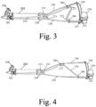
- Figures 3 and 4 illustrate left views following two positions of development of the electrical conductive cord.
- the headband comprises a front part 205 and a rear part 240, connected to each other by means of an elastic tightening link 230.
- the front part 205 is in the form of a headband element, made of textile, plastic or any other suitable material, preferably elastic, on which a lamp body 200 will be fixed.
- Different fixing methods may be envisaged to ensure the maintenance of the lamp body 200 on the element 205 which it is not necessary to detail here for the sake of brevity. It is sufficient to mention, for example, the possibility of providing two loops in the lamp body 200 for the passage of the elastic band so as to ensure a sliding connection of the lamp body 200 on the band element 210. But, clearly, other embodiments are possible and conceivable.
- the strip element 205 comprises two ends, respectively left and right, to which are fixed, preferably by overmolding or sewing, two plastic terminations 210 and 220 each having a through hole or vertical conduit, respectively 211 and 221, intended for the sliding passage of the elastic tightening link 230.
- the plastic terminations 210 and 220 have the shape of a substantially square or rectangular loop, one hollow vertical side of which serves as a passage conduit 211/221 for vertical sliding of the elastic tightening link 230.
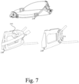
- the plastic termination 210 further comprises a first attachment clip 215, arranged protruding, and which ensures a horizontal sliding connection with an electrically conductive cord 270.
- the detail of the termination 210 is illustrated in the Figure 7 and will be described later.
- the rear portion 240 of the headband consists of a support of substantially symmetrical shape in the median sagittal plane, and configured to match the rear shape of a user's head.
- the support of the rear portion 240 is in the form of a triangle having a base provided with two attachment points, respectively left and right, for the two ends of the elastic tightening link 230.
- the Figure 3 illustrates more specifically the left fixation point 241 of the tightening tie 230, the right attachment point not being visible in the figure.
- the base of the rear part 240 also includes a projection allowing the attachment of a battery body 250 connected to the electric cord 270 via a connector 242.
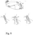
- FIG. 8 illustrates in more detail the rear support 240 and its locking lever 260.
- the tightening possibilities of the proposed headband are significant due to the specific, new and particularly advantageous path of the elastic tightening link 230, which passes successively from the left fixing point 241 on the base of the support of the rear part 240, to then run towards the left vertical sliding conduit 211 of the loop 210, exit from it and join the upper left passing hole of the support of the rear part 240 to form an adjustable loop there, as appears in the figure 8 , and lockable by the locking lever 260 and, on the right side, to exit through the upper right-hand passing hole of the support of the rear part 240, and to join the vertical sliding conduit 221 of the termination 220 to then join the right fixing on the base of the support of the rear part 240.
- Such a path of the elastic tightening link 230 allows a particularly effective and comfortable hold on the head of a user since it leads to the appearance of a double tightening loop, respectively lower and upper, which can be tightened by means of a single locking lever 260.
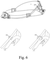
- an electrical conductive cord 270 of very specific shape is provided with two radii of curvature, respectively 271 and 272, falling within a sagittal plane of the user so as to form a “Z” and cooperating advantageously with the path of the tightening tie 230.
- two movable clips 280 and 290 are provided allowing a sliding connection between the electrically conductive cord 270 and the elastic clamping link 230.
- the movable clip 280 is positioned at the first radius of curvature 271 to ensure sliding with the upper part of the elastic clamping link 230, while the movable clip 290 is positioned at the second radius of curvature 272 to allow sliding with the lower part of the elastic clamping link 230.
- FIG. 5 The detail of one embodiment of the movable clip 290 is illustrated in the Figure 5 , while the Figure 6 shows an embodiment of the mobile clip 280 allowing the cooperation of the electrical conductive cord 270 with the elastic link 230.
- the first termination 210 provides a double sliding connection, perpendicular to each other, at the level of the electrical cord 270 and the tightening link 230a/230b.
- the attachment clip 215 allows a substantially horizontal sliding of the electrical cord 270 while the through holes of the loop 210 ensure a vertical sliding.
- the electric battery can be connected to the support of the rear part 240 by means of a micro-USB type connector.
Landscapes
- Engineering & Computer Science (AREA)
- General Engineering & Computer Science (AREA)
- Helmets And Other Head Coverings (AREA)
- Arrangement Of Elements, Cooling, Sealing, Or The Like Of Lighting Devices (AREA)
Claims (8)
- Stirnband für eine Stirnlampe, bestehend aus:einem Vorderteil (205) mit einem Stirnbandelement zur Aufnahme eines Lampenkörpers (200) und zwei Anschlüssen (210, 220), wobei jeder Anschluss (210, 220) eine Durchgangsöffnung oder einen vertikalen Kanal (211, 221) für die gleitende Durchführung eines elastischen Spannglieds (230) und einen ersten Befestigungsclip (215) aufweist, der eine horizontale Gleitverbindung mit einem elektrisch leitfähigen Kabel (270) herstellt;einem hinteren Teil (240), der eine Halterung zur Aufnahme einer elektrischen Batterie und einen Verriegelungshebel (260), wobei die Halterung an ihrer Basis zwei Befestigungspunkte, jeweils links und rechts, für zwei Enden des elastischen Spannglieds (230) aufweist und im oberen Bereich zwei Durchgangslöcher für die Durchführung des elastischen Spannglieds (230) aufweist, das durch den Verriegelungshebel (260) blockiert werden kann;Das elastische Spannglied (230) verläuft vom linken Befestigungspunkt (241) an der Basis des Trägers des hinteren Teils (240) zum vertikalen Kanal (211) eines ersten Anschlusses (210), tritt aus diesem aus und verbindet sich mit der oberen linken Durchgangsöffnung des Trägers, dadurch bildet sich eine verstellbare und verriegelbare Schlaufe, die mit dem Verriegelungshebel (260) verriegelt werden kann, das elastische Spannglied (230) tritt durch die obere rechte Durchgangsöffnung des Trägers aus, verbindet sich mit dem vertikalen kanal (221) eines zweiten Anschlusses (220) und verbindet sich dann mit der rechten Befestigung an der Basis des Trägers.Ein elektrisches Leiterkabel (270);
Dadurch gekennzeichnet,
dass das elektrische Leiterkabel (270) zwei Krümmungsradien (271, 272) aufweist, die ein "Z" bilden;eine erste bewegliche Klammer (280), die am ersten Krümmungsradius (271) positioniert ist, um das Gleiten der elektrisch leitfähigen Leitung (270) mit dem oberen Teil des elastischen Spannglieds (230) zu gewährleisten;eine zweite bewegliche Klammer (290), die auf Höhe des zweiten Krümmungsradius (272) positioniert ist, um das Gleiten der elektrisch leitfähigen Leitung (270) mit dem unteren Teil des elastischen Spannglieds (230) zu ermöglichen. - Stirnband für eine Stirnlampe nach Anspruch 1, dadurch gekennzeichnet, dass ein Abschluss (210) eine doppelte, senkrecht zueinander verlaufende Gleitverbindung für das Stromkabel (270) und das elastische Spannglied (230) bildet.
- Stirnband für eine Stirnlampe nach Anspruch 1 oder 2, dadurch gekennzeichnet, dass die beiden Abschlussstücke (210, 220) vorzugsweise durch Anformen oder Annähen an das elastische Kopfband, das den vorderen Teil bildet, hergestellt sind.
- Stirnband für eine Stirnlampe nach Anspruch 1, wobei die Abschlussstücke (210, 220) die Form einer im Wesentlichen quadratischen oder rechteckigen Schleife haben, deren eine hohle vertikale Seite als Durchgangskanal (211, 221) für die vertikale Gleitbewegung des elastischen Spannglieds (230) dient.
- Stirnband für eine Stirnlampe nach Anspruch 1, wobei die Halterung des hinteren Teils (240) die Form eines Dreiecks hat, dessen Basis mit zwei Befestigungspunkten links und rechts für die beiden Enden des elastischen Spannglieds (230) versehen ist.
- Stirnband für eine Stirnlampe nach Anspruch 1, wobei der Lampenkörper (200) schwenkbar am Stirnband befestigt ist.
- Stirnband für eine Stirnlampe nach Anspruch 1, wobei der Lampenkörper (200) zwei Durchgangslöcher für das Stirnbandelement aufweist.
- Stirnband für eine Stirnlampe nach Anspruch 1, wobei die Halterung des hinteren Teils (240) einen Micro-USB-Anschluss zum Anschluss der Batterie aufweist.
Priority Applications (4)
| Application Number | Priority Date | Filing Date | Title |
|---|---|---|---|
| EP21158833.0A EP4047261B1 (de) | 2021-02-23 | 2021-02-23 | Stirnband für stirnlampe |
| TW111104489A TWI898115B (zh) | 2021-02-23 | 2022-02-08 | 頭燈頭帶 |
| US17/676,514 US11585519B2 (en) | 2021-02-23 | 2022-02-21 | Headlamp headband |
| CN202210167878.9A CN114963137A (zh) | 2021-02-23 | 2022-02-23 | 头灯头带 |
Applications Claiming Priority (1)
| Application Number | Priority Date | Filing Date | Title |
|---|---|---|---|
| EP21158833.0A EP4047261B1 (de) | 2021-02-23 | 2021-02-23 | Stirnband für stirnlampe |
Publications (2)
| Publication Number | Publication Date |
|---|---|
| EP4047261A1 EP4047261A1 (de) | 2022-08-24 |
| EP4047261B1 true EP4047261B1 (de) | 2025-05-21 |
Family
ID=74732682
Family Applications (1)
| Application Number | Title | Priority Date | Filing Date |
|---|---|---|---|
| EP21158833.0A Active EP4047261B1 (de) | 2021-02-23 | 2021-02-23 | Stirnband für stirnlampe |
Country Status (4)
| Country | Link |
|---|---|
| US (1) | US11585519B2 (de) |
| EP (1) | EP4047261B1 (de) |
| CN (1) | CN114963137A (de) |
| TW (1) | TWI898115B (de) |
Families Citing this family (1)
| Publication number | Priority date | Publication date | Assignee | Title |
|---|---|---|---|---|
| USD1015594S1 (en) * | 2021-12-09 | 2024-02-20 | Starforce Incorporated | Head lamp |
Citations (2)
| Publication number | Priority date | Publication date | Assignee | Title |
|---|---|---|---|---|
| USD677816S1 (en) * | 2011-06-16 | 2013-03-12 | Zedel | Headlamp |
| USD828599S1 (en) * | 2016-09-08 | 2018-09-11 | Zedel | Headlamp |
Family Cites Families (9)
| Publication number | Priority date | Publication date | Assignee | Title |
|---|---|---|---|---|
| US20050276036A1 (en) * | 2004-06-14 | 2005-12-15 | Miles Danny L | Explorer lite extreme |
| US7513660B2 (en) * | 2007-06-20 | 2009-04-07 | Eveready Battery Company, Inc. | Lighting device having forward directed heat sink assembly |
| FR2971037A1 (fr) | 2011-02-01 | 2012-08-03 | Zedel | Lampe d'eclairage electrique portative, a fixation perfectionnee |
| FR2973474A1 (fr) * | 2011-03-30 | 2012-10-05 | Zedel | Lampe d'eclairage electrique portative comprenant un connecteur d'alimentation et de communication |
| US9263718B2 (en) * | 2013-02-14 | 2016-02-16 | Acuity Ophthalmics, Llc | Battery kit for use with headset |
| US9707707B2 (en) * | 2013-10-18 | 2017-07-18 | Riverpoint Medical, Llc | Comfortable medical headlamp assembly |
| FR3055394B1 (fr) * | 2016-08-29 | 2018-09-21 | Zedel | Lampe frontale dote d'un bandeau rigide ou semi/rigide |
| FR3055393B1 (fr) * | 2016-08-29 | 2018-09-21 | Zedel | Lampe frontale adaptee pour un tour de cou |
| FR3091328A1 (fr) * | 2018-12-31 | 2020-07-03 | Zedel | Dispositif d’équilibrage améliorant le maintien sur la tête d’une lampe frontale |
-
2021
- 2021-02-23 EP EP21158833.0A patent/EP4047261B1/de active Active
-
2022
- 2022-02-08 TW TW111104489A patent/TWI898115B/zh active
- 2022-02-21 US US17/676,514 patent/US11585519B2/en active Active
- 2022-02-23 CN CN202210167878.9A patent/CN114963137A/zh active Pending
Patent Citations (2)
| Publication number | Priority date | Publication date | Assignee | Title |
|---|---|---|---|---|
| USD677816S1 (en) * | 2011-06-16 | 2013-03-12 | Zedel | Headlamp |
| USD828599S1 (en) * | 2016-09-08 | 2018-09-11 | Zedel | Headlamp |
Also Published As
| Publication number | Publication date |
|---|---|
| EP4047261A1 (de) | 2022-08-24 |
| CN114963137A (zh) | 2022-08-30 |
| US11585519B2 (en) | 2023-02-21 |
| TW202233992A (zh) | 2022-09-01 |
| US20220268429A1 (en) | 2022-08-25 |
| TWI898115B (zh) | 2025-09-21 |
Similar Documents
| Publication | Publication Date | Title |
|---|---|---|
| EP3674596B1 (de) | Ausgleichsvorrichtung zur verbesserung des haltens auf dem kopf einer stirnlampe | |
| US4774648A (en) | Low voltage light fixture | |
| EP2481981B1 (de) | Tragbare elektrische Lampe mit einer perfektionierten Befestigungsvorrichtung | |
| FR2635896A3 (fr) | Dispositif electronique multifonctionnel pour l'autodefense d'une personne | |
| FR2798720A1 (fr) | Dispositif d'eclairage destine a equiper un support, notamment textile | |
| EP4047261B1 (de) | Stirnband für stirnlampe | |
| EP2844098A1 (de) | Schutzhelm für mechanischen, elektrischen und wärmebelastung für elektriker | |
| FR2753840A1 (fr) | Borne de raccordement pour conducteur electrique | |
| FR2870492A1 (fr) | Lampe d'eclairage interieure pour vehicule | |
| EP3293451A1 (de) | Stirnlampe für trageband | |
| FR2833069A1 (fr) | Perfectionnement pour reglage de focale de lampe frontale | |
| FR2833068A1 (fr) | Perfectionnement pour reglage de focale de lampe frontale | |
| EP3290785B1 (de) | Stirnlampe, die mit einem starren oder halbstarren band versehen ist | |
| FR2973474A1 (fr) | Lampe d'eclairage electrique portative comprenant un connecteur d'alimentation et de communication | |
| FR2803440A1 (fr) | Ressort de fixation d'un bloc de jonction ou similaire sur un rail | |
| EP0786274A1 (de) | Bindungsvorrichtung zum Halten eines Schuhs auf einem Schneeschuh | |
| FR2846523A1 (fr) | Dispositif de maintien d'elements amovibles pour casque de protection | |
| FR2816393A1 (fr) | Dispositif d'eclairage comportant un element de rayonnement de la chaleur degagee par une lampe a decharge et un module de circuit | |
| EP0872923B1 (de) | Vorrichtung zur elektrischen Verbindung von mehreren elektrischen Buchsenkontakten | |
| FR2623919A1 (fr) | Monture de lunettes a branches incorporees dans l'epaisseur du corps de la monture | |
| FR2462795A1 (fr) | Connecteur electrique, en particulier pour le raccordement de composants electroniques | |
| FR2629927A1 (fr) | Lunettes a branches escamotables | |
| FR2585479A1 (fr) | Dispositif de montures de lunettes eclairantes | |
| FR2902178A1 (fr) | Lampe individuelle d'eclairage destinee a etre portee par un utilisateur | |
| FR2736418A1 (fr) | Dispositif d'eclairage portatif |
Legal Events
| Date | Code | Title | Description |
|---|---|---|---|
| PUAI | Public reference made under article 153(3) epc to a published international application that has entered the european phase |
Free format text: ORIGINAL CODE: 0009012 |
|
| STAA | Information on the status of an ep patent application or granted ep patent |
Free format text: STATUS: THE APPLICATION HAS BEEN PUBLISHED |
|
| AK | Designated contracting states |
Kind code of ref document: A1 Designated state(s): AL AT BE BG CH CY CZ DE DK EE ES FI FR GB GR HR HU IE IS IT LI LT LU LV MC MK MT NL NO PL PT RO RS SE SI SK SM TR |
|
| STAA | Information on the status of an ep patent application or granted ep patent |
Free format text: STATUS: REQUEST FOR EXAMINATION WAS MADE |
|
| 17P | Request for examination filed |
Effective date: 20230222 |
|
| RBV | Designated contracting states (corrected) |
Designated state(s): AL AT BE BG CH CY CZ DE DK EE ES FI FR GB GR HR HU IE IS IT LI LT LU LV MC MK MT NL NO PL PT RO RS SE SI SK SM TR |
|
| GRAP | Despatch of communication of intention to grant a patent |
Free format text: ORIGINAL CODE: EPIDOSNIGR1 |
|
| STAA | Information on the status of an ep patent application or granted ep patent |
Free format text: STATUS: GRANT OF PATENT IS INTENDED |
|
| RIC1 | Information provided on ipc code assigned before grant |
Ipc: F21L 4/04 20060101ALN20241216BHEP Ipc: F21V 21/084 20060101ALI20241216BHEP Ipc: F21L 4/00 20060101AFI20241216BHEP |
|
| INTG | Intention to grant announced |
Effective date: 20250115 |
|
| GRAS | Grant fee paid |
Free format text: ORIGINAL CODE: EPIDOSNIGR3 |
|
| GRAA | (expected) grant |
Free format text: ORIGINAL CODE: 0009210 |
|
| STAA | Information on the status of an ep patent application or granted ep patent |
Free format text: STATUS: THE PATENT HAS BEEN GRANTED |
|
| AK | Designated contracting states |
Kind code of ref document: B1 Designated state(s): AL AT BE BG CH CY CZ DE DK EE ES FI FR GB GR HR HU IE IS IT LI LT LU LV MC MK MT NL NO PL PT RO RS SE SI SK SM TR |
|
| REG | Reference to a national code |
Ref country code: GB Ref legal event code: FG4D Free format text: NOT ENGLISH |
|
| REG | Reference to a national code |
Ref country code: CH Ref legal event code: EP |
|
| REG | Reference to a national code |
Ref country code: DE Ref legal event code: R096 Ref document number: 602021031000 Country of ref document: DE |
|
| REG | Reference to a national code |
Ref country code: IE Ref legal event code: FG4D Free format text: LANGUAGE OF EP DOCUMENT: FRENCH |
|
| REG | Reference to a national code |
Ref country code: SE Ref legal event code: TRGR |
|
| REG | Reference to a national code |
Ref country code: NL Ref legal event code: MP Effective date: 20250521 |
|
| PG25 | Lapsed in a contracting state [announced via postgrant information from national office to epo] |
Ref country code: FI Free format text: LAPSE BECAUSE OF FAILURE TO SUBMIT A TRANSLATION OF THE DESCRIPTION OR TO PAY THE FEE WITHIN THE PRESCRIBED TIME-LIMIT Effective date: 20250521 Ref country code: PT Free format text: LAPSE BECAUSE OF FAILURE TO SUBMIT A TRANSLATION OF THE DESCRIPTION OR TO PAY THE FEE WITHIN THE PRESCRIBED TIME-LIMIT Effective date: 20250922 Ref country code: ES Free format text: LAPSE BECAUSE OF FAILURE TO SUBMIT A TRANSLATION OF THE DESCRIPTION OR TO PAY THE FEE WITHIN THE PRESCRIBED TIME-LIMIT Effective date: 20250521 |
|
| REG | Reference to a national code |
Ref country code: LT Ref legal event code: MG9D |
|
| PG25 | Lapsed in a contracting state [announced via postgrant information from national office to epo] |
Ref country code: NO Free format text: LAPSE BECAUSE OF FAILURE TO SUBMIT A TRANSLATION OF THE DESCRIPTION OR TO PAY THE FEE WITHIN THE PRESCRIBED TIME-LIMIT Effective date: 20250821 Ref country code: GR Free format text: LAPSE BECAUSE OF FAILURE TO SUBMIT A TRANSLATION OF THE DESCRIPTION OR TO PAY THE FEE WITHIN THE PRESCRIBED TIME-LIMIT Effective date: 20250822 |
|
| PG25 | Lapsed in a contracting state [announced via postgrant information from national office to epo] |
Ref country code: PL Free format text: LAPSE BECAUSE OF FAILURE TO SUBMIT A TRANSLATION OF THE DESCRIPTION OR TO PAY THE FEE WITHIN THE PRESCRIBED TIME-LIMIT Effective date: 20250521 Ref country code: NL Free format text: LAPSE BECAUSE OF FAILURE TO SUBMIT A TRANSLATION OF THE DESCRIPTION OR TO PAY THE FEE WITHIN THE PRESCRIBED TIME-LIMIT Effective date: 20250521 |
|
| PG25 | Lapsed in a contracting state [announced via postgrant information from national office to epo] |
Ref country code: BG Free format text: LAPSE BECAUSE OF FAILURE TO SUBMIT A TRANSLATION OF THE DESCRIPTION OR TO PAY THE FEE WITHIN THE PRESCRIBED TIME-LIMIT Effective date: 20250521 |
|
| PG25 | Lapsed in a contracting state [announced via postgrant information from national office to epo] |
Ref country code: HR Free format text: LAPSE BECAUSE OF FAILURE TO SUBMIT A TRANSLATION OF THE DESCRIPTION OR TO PAY THE FEE WITHIN THE PRESCRIBED TIME-LIMIT Effective date: 20250521 |
|
| PG25 | Lapsed in a contracting state [announced via postgrant information from national office to epo] |
Ref country code: RS Free format text: LAPSE BECAUSE OF FAILURE TO SUBMIT A TRANSLATION OF THE DESCRIPTION OR TO PAY THE FEE WITHIN THE PRESCRIBED TIME-LIMIT Effective date: 20250821 |
|
| PG25 | Lapsed in a contracting state [announced via postgrant information from national office to epo] |
Ref country code: IS Free format text: LAPSE BECAUSE OF FAILURE TO SUBMIT A TRANSLATION OF THE DESCRIPTION OR TO PAY THE FEE WITHIN THE PRESCRIBED TIME-LIMIT Effective date: 20250921 |
|
| PG25 | Lapsed in a contracting state [announced via postgrant information from national office to epo] |
Ref country code: LV Free format text: LAPSE BECAUSE OF FAILURE TO SUBMIT A TRANSLATION OF THE DESCRIPTION OR TO PAY THE FEE WITHIN THE PRESCRIBED TIME-LIMIT Effective date: 20250521 |
|
| REG | Reference to a national code |
Ref country code: AT Ref legal event code: MK05 Ref document number: 1797004 Country of ref document: AT Kind code of ref document: T Effective date: 20250521 |
|
| PG25 | Lapsed in a contracting state [announced via postgrant information from national office to epo] |
Ref country code: DK Free format text: LAPSE BECAUSE OF FAILURE TO SUBMIT A TRANSLATION OF THE DESCRIPTION OR TO PAY THE FEE WITHIN THE PRESCRIBED TIME-LIMIT Effective date: 20250521 Ref country code: AT Free format text: LAPSE BECAUSE OF FAILURE TO SUBMIT A TRANSLATION OF THE DESCRIPTION OR TO PAY THE FEE WITHIN THE PRESCRIBED TIME-LIMIT Effective date: 20250521 Ref country code: SM Free format text: LAPSE BECAUSE OF FAILURE TO SUBMIT A TRANSLATION OF THE DESCRIPTION OR TO PAY THE FEE WITHIN THE PRESCRIBED TIME-LIMIT Effective date: 20250521 |
|
| PG25 | Lapsed in a contracting state [announced via postgrant information from national office to epo] |
Ref country code: CZ Free format text: LAPSE BECAUSE OF FAILURE TO SUBMIT A TRANSLATION OF THE DESCRIPTION OR TO PAY THE FEE WITHIN THE PRESCRIBED TIME-LIMIT Effective date: 20250521 |
|
| PG25 | Lapsed in a contracting state [announced via postgrant information from national office to epo] |
Ref country code: EE Free format text: LAPSE BECAUSE OF FAILURE TO SUBMIT A TRANSLATION OF THE DESCRIPTION OR TO PAY THE FEE WITHIN THE PRESCRIBED TIME-LIMIT Effective date: 20250521 |
|
| PG25 | Lapsed in a contracting state [announced via postgrant information from national office to epo] |
Ref country code: SK Free format text: LAPSE BECAUSE OF FAILURE TO SUBMIT A TRANSLATION OF THE DESCRIPTION OR TO PAY THE FEE WITHIN THE PRESCRIBED TIME-LIMIT Effective date: 20250521 |
|
| PG25 | Lapsed in a contracting state [announced via postgrant information from national office to epo] |
Ref country code: IT Free format text: LAPSE BECAUSE OF FAILURE TO SUBMIT A TRANSLATION OF THE DESCRIPTION OR TO PAY THE FEE WITHIN THE PRESCRIBED TIME-LIMIT Effective date: 20250521 |
|
| PLBE | No opposition filed within time limit |
Free format text: ORIGINAL CODE: 0009261 |
|
| STAA | Information on the status of an ep patent application or granted ep patent |
Free format text: STATUS: NO OPPOSITION FILED WITHIN TIME LIMIT |