EP3674494A1 - Verfahren zur isolierung eines erdgeschosses eines gebäudes - Google Patents
Verfahren zur isolierung eines erdgeschosses eines gebäudes Download PDFInfo
- Publication number
- EP3674494A1 EP3674494A1 EP20150088.1A EP20150088A EP3674494A1 EP 3674494 A1 EP3674494 A1 EP 3674494A1 EP 20150088 A EP20150088 A EP 20150088A EP 3674494 A1 EP3674494 A1 EP 3674494A1
- Authority
- EP
- European Patent Office
- Prior art keywords
- ground floor
- tunnels
- area parts
- locations
- exterior wall
- Prior art date
- Legal status (The legal status is an assumption and is not a legal conclusion. Google has not performed a legal analysis and makes no representation as to the accuracy of the status listed.)
- Granted
Links
Images



Classifications
-
- E—FIXED CONSTRUCTIONS
- E04—BUILDING
- E04B—GENERAL BUILDING CONSTRUCTIONS; WALLS, e.g. PARTITIONS; ROOFS; FLOORS; CEILINGS; INSULATION OR OTHER PROTECTION OF BUILDINGS
- E04B1/00—Constructions in general; Structures which are not restricted either to walls, e.g. partitions, or floors or ceilings or roofs
- E04B1/62—Insulation or other protection; Elements or use of specified material therefor
- E04B1/74—Heat, sound or noise insulation, absorption, or reflection; Other building methods affording favourable thermal or acoustical conditions, e.g. accumulating of heat within walls
- E04B1/76—Heat, sound or noise insulation, absorption, or reflection; Other building methods affording favourable thermal or acoustical conditions, e.g. accumulating of heat within walls specifically with respect to heat only
-
- E—FIXED CONSTRUCTIONS
- E02—HYDRAULIC ENGINEERING; FOUNDATIONS; SOIL SHIFTING
- E02D—FOUNDATIONS; EXCAVATIONS; EMBANKMENTS; UNDERGROUND OR UNDERWATER STRUCTURES
- E02D27/00—Foundations as substructures
- E02D27/32—Foundations for special purposes
- E02D27/48—Foundations inserted underneath existing buildings or constructions
-
- E—FIXED CONSTRUCTIONS
- E04—BUILDING
- E04B—GENERAL BUILDING CONSTRUCTIONS; WALLS, e.g. PARTITIONS; ROOFS; FLOORS; CEILINGS; INSULATION OR OTHER PROTECTION OF BUILDINGS
- E04B1/00—Constructions in general; Structures which are not restricted either to walls, e.g. partitions, or floors or ceilings or roofs
- E04B1/0007—Base structures; Cellars
-
- E—FIXED CONSTRUCTIONS
- E02—HYDRAULIC ENGINEERING; FOUNDATIONS; SOIL SHIFTING
- E02D—FOUNDATIONS; EXCAVATIONS; EMBANKMENTS; UNDERGROUND OR UNDERWATER STRUCTURES
- E02D27/00—Foundations as substructures
- E02D27/01—Flat foundations
-
- E—FIXED CONSTRUCTIONS
- E02—HYDRAULIC ENGINEERING; FOUNDATIONS; SOIL SHIFTING
- E02D—FOUNDATIONS; EXCAVATIONS; EMBANKMENTS; UNDERGROUND OR UNDERWATER STRUCTURES
- E02D27/00—Foundations as substructures
- E02D27/01—Flat foundations
- E02D27/02—Flat foundations without substantial excavation
-
- Y—GENERAL TAGGING OF NEW TECHNOLOGICAL DEVELOPMENTS; GENERAL TAGGING OF CROSS-SECTIONAL TECHNOLOGIES SPANNING OVER SEVERAL SECTIONS OF THE IPC; TECHNICAL SUBJECTS COVERED BY FORMER USPC CROSS-REFERENCE ART COLLECTIONS [XRACs] AND DIGESTS
- Y02—TECHNOLOGIES OR APPLICATIONS FOR MITIGATION OR ADAPTATION AGAINST CLIMATE CHANGE
- Y02A—TECHNOLOGIES FOR ADAPTATION TO CLIMATE CHANGE
- Y02A30/00—Adapting or protecting infrastructure or their operation
- Y02A30/24—Structural elements or technologies for improving thermal insulation
- Y02A30/244—Structural elements or technologies for improving thermal insulation using natural or recycled building materials, e.g. straw, wool, clay or used tires
Definitions
- the field of the invention relates to a method for insulating a ground floor of a building, the ground floor being supported on soil.
- the desire to insulating parts of an existing building after the building has been constructed is commonly known.
- the known building comprising a ground floor, which is supported on soil, a front exterior wall, a back exterior wall, side exterior walls, optionally one or more storeys, each storey having a floor, and a roof.
- the floor which is the ground floor, extends between exterior walls, such as between the front exterior wall and the back exterior wall.
- the exterior walls extend into the ground in order to anchor the building.
- the ground floor is directly supported on soil, which may contain at least one of earth, sand, clay and a like soil material.
- the ground floor contains commonly a base layer of concrete, including a floor covering, such as a wooden layer, a layer of tiles, a resilient floor layer, such as PVC layer, a casted polymer layer or a floor screed containing a cementitious material, provided on top of the base layer.
- a base layer of concrete including a floor covering, such as a wooden layer, a layer of tiles, a resilient floor layer, such as PVC layer, a casted polymer layer or a floor screed containing a cementitious material, provided on top of the base layer.
- the building may loose considerable energy through its ground floor, which is supported on soil, to the underlying soil, when the building is heated. Therefore, a desire exists to reduce energy loss of the building through its ground floor.
- an insulating material needs to be placed on top or below the base layer of the ground floor.
- the floor covering needs to be temporarily removed, and the upper level of the floor is raised, which may run into problems of opening doors. In any way, the thickness of the insulating material is restricted.
- the ground floor including the base layer needs to be removed and be reconstructed after providing the insulating material. This requires a lot of reconstruction activities. In any way the ground floor of the building must be emptied in order to access the ground floor for placing the insulating material.
- a method for insulating a ground floor of a building, the ground floor being supported on soil comprising the steps of:
- first tunnels are formed.
- the number of first tunnels is at least two and may be any suitable number larger than two.
- the first area parts are spaced apart from one another at a predetermined distance in the first direction.
- the corresponding first locations of the first tunnels have said predetermined distance between one another in the first direction.
- the predetermined distance is selected to be at least a minimum distance for supporting the ground floor by soil, which is present between the first locations (i.e. between the first tunnels).
- step b. in each of the first tunnels an insulating material is provided.
- Step b. may be carried out after the forming of all first tunnels in step a.
- each first tunnel, formed in step a. may be directly provided with an insulating material (according to step b.), before forming another first tunnel (according to step a.).
- step c. soil is removed only at second locations below respective second area parts of the ground floor.
- the second area parts are spaced apart from one another in the first direction, which may be the lateral direction of a ground floor.
- the second locations are different from the first locations in the first direction.
- the locations of the second tunnels are different from the first tunnels.
- the ground floor remains supported by soil and/or the insulating material present between the second locations (i.e. between the second tunnels).
- the number of second tunnels is at least two and may be any suitable number larger than two.
- step d in each of the second tunnels an insulating material is provided. After the steps a. - d. the insulating material is present at the first locations and the second locations below the ground floor.
- the insulating material is a thermal insulating material.
- Said thermal insulating material is configured for restricting thermal conductivity.
- said thermal insulating material has a thermal conductivity lambda value ⁇ , which is determined in agreement to NEN 1068, and expressed in W.m -1 .K -1 , which is smaller than 0.200 W.m -1 .K -1 , preferably smaller than 0.100 W.m -1 .K -1 , more preferably in the range of 0.060 W.m -1 .K -1 - 0.020 W.m -1 .K -1 .
- a polyurethane foam having a thermal conductivity lambda value ⁇ of about 0.040 - 0.050 W.m -1 .K -1 .
- Said polyurethane foam may be provided to substantially fill the tunnels.
- the polyurethane foam is configured to support the ground floor at the respective locations, when provided inside the respective tunnels.
- the thermal insulating material arranged to extend over said respective area parts of the ground floor, which corresponds to the locations of the tunnels. In this way a thermal conductivity between the ground floor and the soil below the tunnels, which contain the thermal insulating material, is retricted.
- the insulating material is a seismic insulating material.
- each of the respective tunnels may have any suitable dimension and/or shape for accommodating an insulating material.
- the tunnel may be a channel, may be a recess, may be a hole and may have any suitable dimensions.
- each of the tunnels extends in a longitudinal direction.
- the longitudinal direction of each tunnel is arranged substantially parallel to one another.
- the longitudinal direction of each tunnel is arranged substantially perpendicular to the first direction.
- the predetermined distance between the first locations of first tunnels, which are adjacent to one another is substantially the same to a width in the first direction of the second tunnel, which is formed between the adjacent first tunnels.
- the predetermined distance is between 200 mm and 600 mm in the first direction, preferably between 200 mm and 300 mm, more preferably about 250 mm.
- the first locations and the second locations are arranged adjacent to one another, thereby cooperatively spanning the ground floor in the first direction.
- the first locations and the second locations are arranged alternating one another in the first direction.
- the area below the ground floor may be insulated by providing the insulating material in the respective tunnels.
- the first tunnels and the second tunnels alternate one another, thereby cooperatively spanning the ground floor in the first direction.
- the ground floor contains third area parts arranged adjacent to at least one area part of the first area parts and the second area parts in the first direction, which third area parts are not covered by any one of the first area parts and the second area parts.
- the method may comprise further steps of: removing soil, which is arranged for supporting the ground floor, at third locations below respective third area parts of the ground floor, wherein the third area parts are spaced apart from one another in the first direction, thereby forming a plurality of third tunnels below the ground floor; wherein the third locations are different from the first locations and the second locations in the first direction; and providing an insulating material in each of the third tunnels.
- the ground floor contains one third area part arranged adjacent to at least one of the first area parts and the second area parts in the first direction, which is not covered by any one of the first area parts and the second area parts.
- the insulating material provided in the respective tunnel is arranged for supporting the ground floor at the respective location.
- the insulating material is selected to be sufficiently strong to support the ground floor at the respective locations.
- the insulating material is provided in the respective tunnels in such a way to substantially fill the respective tunnels.
- the insulating material is insulating pressure resistant foam, which is injected into the respective tunnel. The insulating foam may be injected to extend over substantially the whole depth and/or length of the tunnel to support the ground floor at the respective location above the tunnel.
- first tunnels and the second tunnels are extending in a second direction, which is substantially perpendicular to the first direction.
- the second direction may be arranged parallel to a longitudinal direction of the respective tunnel.
- a longitudinal direction is defined as a longest dimension direction of the tunnel.
- step a. and b. are carried out before step c. In this way, in each of the first tunnels an insulating material is provided, before forming the second tunnels.
- the first area parts and the second area parts are arranged contiguous to one another in the first direction.
- the first area parts and the second area parts may cooperatively span at least a part of the ground floor in the first direction.
- the insulating material provided in the first tunnels and the second tunnels may span and insulate the ground floor over the first direction.
- the method further comprising the steps of:
- the third area parts and the fourth area parts are arranged contiguous to one another in the first direction.
- the first area parts and the second area parts together form a front side floor area (F) and the third area parts and the fourth area parts together form a back side floor area (B), wherein the front side floor area (F) is arranged contiguous to the back side floor area (B).
- the front side floor area is arranged adjacent to a front exterior wall and the back side floor area is arranged adjacent to a back exterior wall.
- each of the tunnels is arranged at a level (in a height direction) arranged between the front exterior wall and the back exterior wall and the thermal insulating material is provided inside the tunnels at said level between the front exterior wall and the back exterior wall.
- the tunnels including the thermal insulating material are arranged close to the ground floor in the height direction. This position enhances the thermal insulating of the ground floor.
- each of the third tunnels is arranged in an extension direction of the second tunnels and each of the fourth tunnels is arranged in an extension direction of the first tunnels.
- the steps a. and b. are carried out before steps e. and f., which are carried out before steps c. and d., which are carried out before steps g. and h.
- the building has a front exterior wall and a back exterior wall, the ground floor extending between the front exterior wall and the back exterior wall in a second direction, which is substantially perpendicular to the first direction, wherein the method further comprises the steps of providing holes at predetermined locations in the front exterior wall and / or at predetermined locations in the back exterior wall to provide access to the soil, which is arranged for supporting the ground floor, at respective locations below corresponding area parts of the ground floor.
- the tunnel is formed by moving a ground suction hose of a ground suction device though a respective hole of the front exterior wall or the back exterior wall and moving the ground suction hose beneath the ground floor along a second direction, perpendicular to the first direction, while the ground suction device is arranged for removing soil.
- the method further comprises at least one of the steps of excavating a hole adjacent to the front exterior wall to provide access to the front exterior wall below the ground level and excavating a hole adjacent to the back exterior wall to provide access to the back exterior wall below the ground level.
- the excavating step is carried out before the corresponding steps of removing soil at the respective locations (a., c., e. and /or g.).
- the soil is removed at the respective locations by using a ground suction device.
- the insulating material is provided by injecting a foam material into the respective tunnel.
- the insulating material may be a pressure resistant foam, such as a pressure resistant polyurethane (PUR) foam.
- PUR pressure resistant polyurethane
- PUR foams are generally known.
- each of the respective tunnels has a width between 200 mm and 600 mm in the first direction, preferably between 200 mm and 300 mm, more preferably about 250 mm, optionally each of the respective tunnels has a depth between 200 mm and 600 mm, preferably between 300 mm and 500 mm, more preferably about 400 mm, and optionally each of the respective tunnels has a length in the second direction of at most 6000 mm, preferably at most 4500 mm
- Figure 1A illustrates schematically a front side view of a building.
- the building 100 has a front exterior wall 110 and a ground floor 10.
- the ground floor 10 is at ground level G in a height direction.
- the ground floor 10 is supported on soil.
- the front exterior wall 110 extends into the soil for anchoring the building 100.
- Figure 1B illustrates schematically a back side view of the building.
- the building 100 has a back exterior wall 120.
- the ground floor 10 is shown at ground level G in a height direction.
- the back exterior wall 120 extends into the soil for anchoring the building 100.
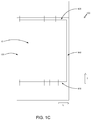
- Figure 1C illustrates schematically a plane view on the ground floor of the building.
- the ground floor 100 extends between the front exterior wall 110 and the back exterior wall 120 in a second direction T and extends between two side walls 130, 140 in a first, lateral L, direction.
- the whole area of the ground floor 100 may be supported on soil.
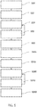
- FIG. 2 illustrates schematically a flow diagram of a method for insulating a ground floor of a building shown in FIG. 1A - 1C .
- Step S10 of the method is excavating a hole 26 adjacent to the front exterior wall 110 to provide access to the front exterior wall 110 below ground level G.
- Step 10 is optional. In case front exterior wall 110 is already accessible below ground level G, the step S10 does not need to be performed.
- the hole 26 may be about 600 mm deep at the front exterior wall 110 and about 2000 mm in width.
- Step S20 is providing holes 131 in the front exterior wall 110 at selected locations to provide access to the soil below the ground floor 10, as shown in FIG. 3A .
- the holes 131 are spaced apart from each other in the first direction L at a predetermined distance.
- the holes 131 may have a size of about 400 mm in diameter.
- Step S30 is removing soil 20, which is arranged for supported the ground floor 10, at first locations below respective first area parts 11 of the ground floor, as shown in FIG. 3B , thereby forming a plurality of corresponding first tunnels 21.
- the first tunnels 21 are located below the ground floor 10 at the respective first area parts 11 of the ground floor.
- the first area parts 11, and the first tunnels 21, are spaced apart from each other in the first direction L at a predetermined distance.
- the predetermined distance preferably corresponds to the predetermined distance between the holes 131.
- the respective tunnels 21 are arranged substantially parallel to one another.
- the respective tunnels 21 have a longitudinal length which is about half a length of the ground floor 10 in the second direction T.
- Step S40 is providing an insulating material 30 in each of the first tunnels 21.
- the insulating material may be a thermal insulating foam material, such as PUR foam, which is injected into the tunnel 21.
- the insulating material 30 may be any other suitable thermal insulating material.
- the insulating material inside the first tunnel 21 is provided to support the ground floor at the respective area part of the ground floor 11.
- Step S40 may be performed after forming all tunnels in step S30.
- Steps S30 and S40 may be performed tunnelwise for each tunnel; thus step S40 after forming the respective tunnel according to step S30 and before forming another tunnel according to step S30.
- Step S50 is the closing of the holes 131 of the front exterior wall 110, optionally including providing an insulating material inside a recess of the front exterior wall 110 near the location of the holes 131.
- Step S110 of the method is excavating a hole 26 adjacent to the back exterior wall 120 to provide access to the back exterior wall 120 below ground level G.
- Step 110 is optional. In case back exterior wall 120 is already accessible below ground level G, the step S110 does not need to be performed.
- the hole 26 may be about 600 mm deep at the back exterior wall 120 and about 2000 mm in width.
- Step S120 is providing holes 133 in the back exterior wall 120 at selected locations to provide access to the soil below the ground floor 10, as shown in FIG. 3C .
- the holes 133 are spaced apart from each other in the first direction L at a predetermined distance.
- the holes 133 may have a size of about 400 mm in diameter.
- Step S130 is removing soil 20, which is arranged for supported the ground floor 10, at third locations below respective third area parts 13 of the ground floor, as shown in FIG. 3D , thereby forming a plurality of corresponding third tunnels 23.
- the third tunnels 23 are located below the ground floor 10 at the respective third area parts 13 of the ground floor.
- the third area parts 13, and the third tunnels 23, are spaced apart from each other in the first direction L at a predetermined distance.
- the predetermined distance preferably corresponds to the predetermined distance between the holes 133.
- the respective tunnels 23 are arranged substantially parallel to one another.
- the respective tunnels 23 have a longitudinal length which is about half a length of the ground floor 10 in the second direction T.
- Step S140 is providing an insulating material 30 in each of the third tunnels 23.
- the insulating material may be an insulating foam material, such as PUR foam, which is injected into the tunnel 23.
- the insulating material 30 may be any other suitable material.
- the insulating material inside the third tunnel 23 is provided to support the ground floor at the respective area part of the ground floor 13.
- Step S140 may be performed after forming all tunnels in step S130.
- Steps S130 and S140 may be performed tunnelwise for each tunnel; thus step S140 after forming the respective tunnel according to step S130 and before forming another tunnel according to step S130.
- Step S150 is the closing of the holes 133 of the back exterior wall 120, optionally including providing an insulating material inside a recess of the back exterior wall 120 near the location of the holes 133.
- Step S220 is providing holes 132 in the front exterior wall 110 at selected locations to provide access to the soil below the ground floor 10, as shown in FIG. 3E .
- the holes 132 are spaced apart from each other in the first direction L at a predetermined distance.
- the holes 132 may have a size of about 400 mm in diameter.
- the holes 132 are at a different location then the holes 131 of step S20.
- the holes 132 and the holes 131 are arranged in an alternating sequence to one another in the first direction L.
- Step S220 may be performed substantially at the same time as Step S20 and before steps S30 - S50.
- step S220 is performed after steps S30 - S50 to prevent an incorrect order of selecting locations to remove soil under the ground floor 10.
- Step S230 is removing soil 20, which is arranged for supported the ground floor 10, at second locations below respective second area parts 12 of the ground floor, as shown in FIG. 3F , thereby forming a plurality of corresponding second tunnels 22.
- the second tunnels 22 are located below the ground floor 10 at the respective second area parts 12 of the ground floor.
- the second area parts 12, and the second tunnels 22, are spaced apart from each other in the first direction L at predetermined distance.
- the predetermined distance preferably corresponds to the predetermined distance between the holes 132.
- the respective tunnels 22 are arranged substantially parallel to one another.
- the second locations are different from the first locations in the first direction L. As such, the locations of the second tunnels 22 are different from the first tunnels 21.
- the respective tunnels 22 have a longitudinal length which is about half a length of the ground floor 10 in the second direction T.
- the second tunnels 22 have a longitudinal length which is arranged in an extension direction of the longitudinal length of the third tunnels 23.
- the predetermined distance between the first locations 11 of first tunnels 21, which are adjacent to one another is substantially the same to a width in the first direction L of the second tunnel 22, which is formed between the adjacent first tunnels 21.
- the predetermined distance is between 200 mm and 600 mm in the first direction, preferably between 200 mm and 300 mm, more preferably about 250 mm
- Step S240 is providing an insulating material 30 in each of the second tunnels 22.
- the insulating material may be an insulating foam material, such as PUR foam, which is injected into the tunnel 22.
- the insulating material 30 may be any other suitable material.
- the insulating material inside the second tunnel 22 is provided to support the ground floor at the respective area part of the ground floor 12.
- Step S240 may be performed after forming all tunnels in step S230.
- Steps S230 and S240 may be performed tunnelwise for each tunnel; thus step S240 after forming the respective tunnel according to step S230 and before forming another tunnel according to step S230.
- Step S250 is the closing of the holes 132 of the front exterior wall 110, optionally including providing an insulating material inside a recess of the front exterior wall 110 near the location of the holes 132.
- Step S320 is providing holes 134 in the back exterior wall 120 at selected locations to provide access to the soil below the ground floor 10, as shown in FIG. 3G .
- the holes 134 are spaced apart from each other in the first direction L at a predetermined distance.
- the holes 134 may have a size of about 400 mm in diameter.
- the holes 134 are at a different location then the holes 133 of step S120.
- the holes 134 and the holes 133 are arranged in an alternating sequence to one another in the first direction L.
- Step S330 is removing soil 20, which is arranged for supported the ground floor 10, at fourth locations below respective fourth area parts 14 of the ground floor, as shown in FIG. 3H , thereby forming a plurality of corresponding fourth tunnels 24.
- the fourth tunnels 24 are located below the ground floor 10 at the respective fourth area parts 14 of the ground floor.
- the fourth area parts 14, and the fourth tunnels 24, are spaced apart from each other in the first direction L at predetermined distance.
- the predetermined distance preferably corresponds to the predetermined distance between the holes 134.
- the respective tunnels 24 are arranged substantially parallel to one another.
- the fourth locations are different from the third locations in the first direction L.
- the locations of the fourth tunnels 24 are different from the third tunnels 23.
- the respective tunnels 24 have a longitudinal length which is about half a length of the ground floor 10 in the second direction T.
- the fourth tunnels 24 have a longitudinal length which is arranged in an extension direction of the longitudinal length of the first tunnels 21.
- the predetermined distance between the third locations 13 of third tunnels 23, which are adjacent to one another is substantially the same to a width in the first direction L of the fourth tunnel 24, which is formed between the adjacent third tunnels 23.
- the predetermined distance is between 200 mm and 600 mm in the first direction, preferably between 200 mm and 300 mm, more preferably about 250 mm.
- Step S340 is providing an insulating material 30 in each of the fourth tunnels 24.
- the insulating material may be an insulating foam material, such as PUR foam, which is injected into the tunnel 24.
- the insulating material 30 may be any other suitable material.
- the insulating material inside the fourth tunnel 24 is provided to support the ground floor at the respective area part of the ground floor 14.
- Step S340 may be performed after forming all tunnels in step S330.
- Steps S330 and S340 may be performed tunnelwise for each tunnel; thus step S340 after forming the respective tunnel according to step S330 and before forming another tunnel according to step S330.
- Step S350 is the closing of the holes 134 of the back exterior wall 120, optionally including providing an insulating material inside a recess of the back exterior wall 120 near the location of the holes 134.
- the first area parts 11 and the second area parts 12 together form a front side floor area F and the third area parts 13 and the fourth area parts 14 together form a back side floor area B, wherein the front side floor area F is arranged contiguous to the back side floor area B.
- the front side floor area F is arranged adjacent to a front exterior wall 110 and the back side floor area b is arranged adjacent to a back exterior wall 120.
- step S50 may be performed later during step S250 and step S150 may be performed later during step S350.
- FIG. 4A illustrates schematically a detailed cross section view of the ground floor and an exterior wall in a first stage.
- the detailed cross section view shows a part of the front exterior wall 110 or the back exterior wall 120 and a part of the ground floor 10 along a height direction D and a second direction T.
- the ground floor 10 is arranged at ground level G in a height direction D and is supported on soil 20.
- the ground floor 10 comprises a base layer 10a and a floor covering 10b.
- the base layer 10a may consist of concrete material.
- the floor covering 10b may comprise at least one of a wooden layer, a layer of tiles, a resilient floor layer, such as PVC layer, a casted polymer layer or a floor screed containing a cementitious material.
- the floor covering 10b is provided on top of the base layer 10a.
- the building may loose considerable energy through its ground floor10 to the underlying soil 20, when the building is heated. Therefore, a desire exists to reduce energy loss of the building through its ground floor 10.
- FIG. 4B illustrates schematically a detailed cross section view of the ground floor and an exterior wall in a second stage along a height direction D and a second direction T.
- an insulating material 30 is provided below the ground floor 10 at selected locations.
- the insulating material 30 is provided by first forming a respective tunnel 21 - 24 at the selected locations according to methods of the present invention.
- each of the tunnels is arranged at a level (in the height direction D) arranged between the front exterior wall and the back exterior wall and the thermal insulating material is provided inside the tunnels at said level between the front exterior wall and the back exterior wall.
- the insulating material 30 is provided substantially directly below the ground floor 10 at selected locations.
- the insulating material 30 may be a thermal insulating foam, such as a pressure resistant PUR foam material.
- the second stage may be obtained after respective steps S40, S140, S240 and S340 at the respective locations of these steps.
- FIG. 5 illustrates schematically another flow diagram of a method for insulating a ground floor of a building shown in FIG. 1A - 1C .
- the method shown in FIG. 5 is a modified method of the method shown in FIG. 2 .
- the ground floor 10 is merely divided in first area parts 10 and second area parts 20, as shown in FIG. 6.
- Each of the first area parts 11 and second area parts 12 extends between the front exterior wall 110 and the back exterior wall 120.
- the method comprises steps S10 - S50 and steps S220 - S250 as described for the flow diagram of FIG. 2 .
- the insulating material 30 is provided below the first area parts 11 and after the steps S220 - S250, the insulating material 30 is provided below the second area parts 12.
- the first area parts 11 and the second area parts 12 cooperatively extend over the whole ground floor 10 in both the first direction L and the second direction T.
- At least one of the series of steps S10 - S50 and S220 - S250 is performed by accessing the soil beneath the ground floor 10 from another exterior wall, such as the back exterior wall 120 or a side exterior wall 130, 140.
- the respective holes made in steps S20 and S220 are made in the respective exterior wall 120, 130, 140 to access the soil beneath the ground floor 10 from said other exterior wall 120, 130, 140.
- the method may comprise an optional step S410 of excavating a hole 26 adjacent to the respective exterior wall to provide access to the respective exterior wall below ground level G.
- Step 410 is optional. In case the exterior wall is already accessible below ground level G, the step S410 does not need to be performed.
- the hole 26 may be about 600 mm deep at the back exterior wall 120 and about 2000 mm in width.
- said thermal insulating material may have a thermal conductivity lambda value ⁇ , which is determined in agreement to NEN 1068, and expressed in W.m-1.K-1, which is smaller than 0.200 W.m-1.K-1, preferably smaller than 0.100 W.m-1.K-1, more preferably in the range of 0.060 W.m-1.K-1 - 0.020 W.m-1.K-1.
- a polyurethane foam is used having a thermal conductivity lambda value ⁇ of about 0.040 - 0.050.
- the soil may be controllably removed by using an installation comprising a ground suction device, such as a KOKS MegaVac installation. Any other suitable installation comprising a ground suction device may be used.
- the insulating material may be provided by injecting a foam material into the respective tunnel by using an Evolution G-30H hydraulic proportioning unit.
- a hydraulic proportioning unit or an air driven proportioning unit may be used. Any other installation for injecting a foam material into the respective tunnel may be used.
- the insulating material in particular thermal insulating material, used may be a pressure resistant polyurethane (PUR) foam material under the name Elastospray ® supplied by BASF.
- PUR pressure resistant polyurethane
- the polyurethane foam has suitable low thermal conductivity properties expressed in lambda value and suitable compressive strength. Any other suitable thermal insulating material may be used.
Landscapes
- Engineering & Computer Science (AREA)
- Structural Engineering (AREA)
- Architecture (AREA)
- Civil Engineering (AREA)
- Physics & Mathematics (AREA)
- Electromagnetism (AREA)
- Mining & Mineral Resources (AREA)
- Paleontology (AREA)
- General Life Sciences & Earth Sciences (AREA)
- General Engineering & Computer Science (AREA)
- Life Sciences & Earth Sciences (AREA)
- Acoustics & Sound (AREA)
- Lining And Supports For Tunnels (AREA)
- Excavating Of Shafts Or Tunnels (AREA)
Applications Claiming Priority (1)
| Application Number | Priority Date | Filing Date | Title |
|---|---|---|---|
| NL2022323A NL2022323B1 (en) | 2018-12-28 | 2018-12-28 | A method for insulating a ground floor of a building |
Publications (2)
| Publication Number | Publication Date |
|---|---|
| EP3674494A1 true EP3674494A1 (de) | 2020-07-01 |
| EP3674494B1 EP3674494B1 (de) | 2021-08-04 |
Family
ID=66049639
Family Applications (1)
| Application Number | Title | Priority Date | Filing Date |
|---|---|---|---|
| EP20150088.1A Active EP3674494B1 (de) | 2018-12-28 | 2020-01-02 | Verfahren zur isolierung eines erdgeschosses eines gebäudes |
Country Status (2)
| Country | Link |
|---|---|
| EP (1) | EP3674494B1 (de) |
| NL (1) | NL2022323B1 (de) |
Citations (3)
| Publication number | Priority date | Publication date | Assignee | Title |
|---|---|---|---|---|
| JPH11256596A (ja) * | 1998-03-16 | 1999-09-21 | Nakamura Bussan Kk | 建造物における基礎構造の補強構造及び補強工法 |
| GB2428698A (en) * | 2005-07-30 | 2007-02-07 | Glenn Melvin | Hardcore substitute |
| EP2553176A2 (de) * | 2010-04-02 | 2013-02-06 | Agenzia Nazionale Per Le Nuove Tecnologie, L'Energia E Lo Sviluppo Economico Sostenibile (ENEA) | Seismische isolierstruktur für bestehende gebäude |
-
2018
- 2018-12-28 NL NL2022323A patent/NL2022323B1/en not_active IP Right Cessation
-
2020
- 2020-01-02 EP EP20150088.1A patent/EP3674494B1/de active Active
Patent Citations (3)
| Publication number | Priority date | Publication date | Assignee | Title |
|---|---|---|---|---|
| JPH11256596A (ja) * | 1998-03-16 | 1999-09-21 | Nakamura Bussan Kk | 建造物における基礎構造の補強構造及び補強工法 |
| GB2428698A (en) * | 2005-07-30 | 2007-02-07 | Glenn Melvin | Hardcore substitute |
| EP2553176A2 (de) * | 2010-04-02 | 2013-02-06 | Agenzia Nazionale Per Le Nuove Tecnologie, L'Energia E Lo Sviluppo Economico Sostenibile (ENEA) | Seismische isolierstruktur für bestehende gebäude |
Also Published As
| Publication number | Publication date |
|---|---|
| NL2022323B1 (en) | 2020-07-23 |
| EP3674494B1 (de) | 2021-08-04 |
Similar Documents
| Publication | Publication Date | Title |
|---|---|---|
| KR101041274B1 (ko) | 합성형 그라우팅 가시설 구조 및 이의 시공방법 | |
| US8011158B1 (en) | Footing for support of structure such as building | |
| KR20130062566A (ko) | 지하수 배수장치 및 그 시공방법 | |
| KR101680072B1 (ko) | 지하주차장 바닥의 소음개선공법 | |
| EP3674494B1 (de) | Verfahren zur isolierung eines erdgeschosses eines gebäudes | |
| US7866097B1 (en) | Radon venting concrete forms | |
| KR20110136258A (ko) | 지하 합성 외벽 구조물 시공 방법 및 이에 의해 시공된 지하 합성 외벽 구조물 | |
| US9416515B2 (en) | Device and method for keeping humidity/water away from concrete foundations and provide insulation | |
| JPH11148231A (ja) | 組積造建物の補強構造および補強方法ならびに免震化工法 | |
| JPH09184144A (ja) | 既存建物の免震ピット構築方法 | |
| CN114232601B (zh) | 一种管线下围护结构墙体施工方法 | |
| JPH07310329A (ja) | 建築物の基礎構造およびその構築方法 | |
| US3830069A (en) | Novel method for constructing subjacent foundation | |
| US9074335B2 (en) | Device and method for keeping humidity/water away from concrete foundations and provide insulation | |
| JP7832057B2 (ja) | 駅ホームの補強構造 | |
| RU215428U1 (ru) | Комбинированная свая с термостабилизатором | |
| JP4581419B2 (ja) | 免震化区画 | |
| KR101765061B1 (ko) | 매입말뚝 고정장치 | |
| KR101325717B1 (ko) | 배수판 조립체 | |
| JPH09273160A (ja) | 低層建築物用基礎構造及び構築方法 | |
| KR101219450B1 (ko) | 지중 차수벽을 이용한 건축 구조물 및 그 시공방법 | |
| JP6445276B2 (ja) | 境界ブロック設置の施工方法 | |
| CA2935224C (en) | Device and method for keeping humidity/water away from concrete foundations and provide insulation | |
| US6508609B2 (en) | Method of forming an in-situ void system | |
| JP2019100058A (ja) | 地盤改良ベタ基礎工法 |
Legal Events
| Date | Code | Title | Description |
|---|---|---|---|
| PUAI | Public reference made under article 153(3) epc to a published international application that has entered the european phase |
Free format text: ORIGINAL CODE: 0009012 |
|
| STAA | Information on the status of an ep patent application or granted ep patent |
Free format text: STATUS: THE APPLICATION HAS BEEN PUBLISHED |
|
| AK | Designated contracting states |
Kind code of ref document: A1 Designated state(s): AL AT BE BG CH CY CZ DE DK EE ES FI FR GB GR HR HU IE IS IT LI LT LU LV MC MK MT NL NO PL PT RO RS SE SI SK SM TR |
|
| AX | Request for extension of the european patent |
Extension state: BA ME |
|
| STAA | Information on the status of an ep patent application or granted ep patent |
Free format text: STATUS: REQUEST FOR EXAMINATION WAS MADE |
|
| 17P | Request for examination filed |
Effective date: 20201228 |
|
| RBV | Designated contracting states (corrected) |
Designated state(s): AL AT BE BG CH CY CZ DE DK EE ES FI FR GB GR HR HU IE IS IT LI LT LU LV MC MK MT NL NO PL PT RO RS SE SI SK SM TR |
|
| GRAP | Despatch of communication of intention to grant a patent |
Free format text: ORIGINAL CODE: EPIDOSNIGR1 |
|
| STAA | Information on the status of an ep patent application or granted ep patent |
Free format text: STATUS: GRANT OF PATENT IS INTENDED |
|
| RIC1 | Information provided on ipc code assigned before grant |
Ipc: E02D 27/02 20060101ALN20210129BHEP Ipc: E04B 1/76 20060101ALI20210129BHEP Ipc: E04B 1/00 20060101AFI20210129BHEP Ipc: E02D 27/48 20060101ALI20210129BHEP Ipc: E02D 27/01 20060101ALN20210129BHEP |
|
| INTG | Intention to grant announced |
Effective date: 20210305 |
|
| GRAS | Grant fee paid |
Free format text: ORIGINAL CODE: EPIDOSNIGR3 |
|
| GRAA | (expected) grant |
Free format text: ORIGINAL CODE: 0009210 |
|
| STAA | Information on the status of an ep patent application or granted ep patent |
Free format text: STATUS: THE PATENT HAS BEEN GRANTED |
|
| AK | Designated contracting states |
Kind code of ref document: B1 Designated state(s): AL AT BE BG CH CY CZ DE DK EE ES FI FR GB GR HR HU IE IS IT LI LT LU LV MC MK MT NL NO PL PT RO RS SE SI SK SM TR |
|
| REG | Reference to a national code |
Ref country code: GB Ref legal event code: FG4D |
|
| REG | Reference to a national code |
Ref country code: AT Ref legal event code: REF Ref document number: 1417128 Country of ref document: AT Kind code of ref document: T Effective date: 20210815 |
|
| REG | Reference to a national code |
Ref country code: CH Ref legal event code: EP |
|
| REG | Reference to a national code |
Ref country code: DE Ref legal event code: R096 Ref document number: 602020000297 Country of ref document: DE |
|
| REG | Reference to a national code |
Ref country code: IE Ref legal event code: FG4D |
|
| REG | Reference to a national code |
Ref country code: LT Ref legal event code: MG9D |
|
| REG | Reference to a national code |
Ref country code: NL Ref legal event code: FP |
|
| REG | Reference to a national code |
Ref country code: AT Ref legal event code: MK05 Ref document number: 1417128 Country of ref document: AT Kind code of ref document: T Effective date: 20210804 |
|
| PG25 | Lapsed in a contracting state [announced via postgrant information from national office to epo] |
Ref country code: SE Free format text: LAPSE BECAUSE OF FAILURE TO SUBMIT A TRANSLATION OF THE DESCRIPTION OR TO PAY THE FEE WITHIN THE PRESCRIBED TIME-LIMIT Effective date: 20210804 Ref country code: RS Free format text: LAPSE BECAUSE OF FAILURE TO SUBMIT A TRANSLATION OF THE DESCRIPTION OR TO PAY THE FEE WITHIN THE PRESCRIBED TIME-LIMIT Effective date: 20210804 Ref country code: ES Free format text: LAPSE BECAUSE OF FAILURE TO SUBMIT A TRANSLATION OF THE DESCRIPTION OR TO PAY THE FEE WITHIN THE PRESCRIBED TIME-LIMIT Effective date: 20210804 Ref country code: FI Free format text: LAPSE BECAUSE OF FAILURE TO SUBMIT A TRANSLATION OF THE DESCRIPTION OR TO PAY THE FEE WITHIN THE PRESCRIBED TIME-LIMIT Effective date: 20210804 Ref country code: HR Free format text: LAPSE BECAUSE OF FAILURE TO SUBMIT A TRANSLATION OF THE DESCRIPTION OR TO PAY THE FEE WITHIN THE PRESCRIBED TIME-LIMIT Effective date: 20210804 Ref country code: NO Free format text: LAPSE BECAUSE OF FAILURE TO SUBMIT A TRANSLATION OF THE DESCRIPTION OR TO PAY THE FEE WITHIN THE PRESCRIBED TIME-LIMIT Effective date: 20211104 Ref country code: PT Free format text: LAPSE BECAUSE OF FAILURE TO SUBMIT A TRANSLATION OF THE DESCRIPTION OR TO PAY THE FEE WITHIN THE PRESCRIBED TIME-LIMIT Effective date: 20211206 Ref country code: AT Free format text: LAPSE BECAUSE OF FAILURE TO SUBMIT A TRANSLATION OF THE DESCRIPTION OR TO PAY THE FEE WITHIN THE PRESCRIBED TIME-LIMIT Effective date: 20210804 Ref country code: BG Free format text: LAPSE BECAUSE OF FAILURE TO SUBMIT A TRANSLATION OF THE DESCRIPTION OR TO PAY THE FEE WITHIN THE PRESCRIBED TIME-LIMIT Effective date: 20211104 Ref country code: LT Free format text: LAPSE BECAUSE OF FAILURE TO SUBMIT A TRANSLATION OF THE DESCRIPTION OR TO PAY THE FEE WITHIN THE PRESCRIBED TIME-LIMIT Effective date: 20210804 |
|
| PG25 | Lapsed in a contracting state [announced via postgrant information from national office to epo] |
Ref country code: PL Free format text: LAPSE BECAUSE OF FAILURE TO SUBMIT A TRANSLATION OF THE DESCRIPTION OR TO PAY THE FEE WITHIN THE PRESCRIBED TIME-LIMIT Effective date: 20210804 Ref country code: LV Free format text: LAPSE BECAUSE OF FAILURE TO SUBMIT A TRANSLATION OF THE DESCRIPTION OR TO PAY THE FEE WITHIN THE PRESCRIBED TIME-LIMIT Effective date: 20210804 Ref country code: GR Free format text: LAPSE BECAUSE OF FAILURE TO SUBMIT A TRANSLATION OF THE DESCRIPTION OR TO PAY THE FEE WITHIN THE PRESCRIBED TIME-LIMIT Effective date: 20211105 |
|
| PG25 | Lapsed in a contracting state [announced via postgrant information from national office to epo] |
Ref country code: DK Free format text: LAPSE BECAUSE OF FAILURE TO SUBMIT A TRANSLATION OF THE DESCRIPTION OR TO PAY THE FEE WITHIN THE PRESCRIBED TIME-LIMIT Effective date: 20210804 |
|
| REG | Reference to a national code |
Ref country code: DE Ref legal event code: R097 Ref document number: 602020000297 Country of ref document: DE |
|
| PG25 | Lapsed in a contracting state [announced via postgrant information from national office to epo] |
Ref country code: SM Free format text: LAPSE BECAUSE OF FAILURE TO SUBMIT A TRANSLATION OF THE DESCRIPTION OR TO PAY THE FEE WITHIN THE PRESCRIBED TIME-LIMIT Effective date: 20210804 Ref country code: SK Free format text: LAPSE BECAUSE OF FAILURE TO SUBMIT A TRANSLATION OF THE DESCRIPTION OR TO PAY THE FEE WITHIN THE PRESCRIBED TIME-LIMIT Effective date: 20210804 Ref country code: RO Free format text: LAPSE BECAUSE OF FAILURE TO SUBMIT A TRANSLATION OF THE DESCRIPTION OR TO PAY THE FEE WITHIN THE PRESCRIBED TIME-LIMIT Effective date: 20210804 Ref country code: EE Free format text: LAPSE BECAUSE OF FAILURE TO SUBMIT A TRANSLATION OF THE DESCRIPTION OR TO PAY THE FEE WITHIN THE PRESCRIBED TIME-LIMIT Effective date: 20210804 Ref country code: CZ Free format text: LAPSE BECAUSE OF FAILURE TO SUBMIT A TRANSLATION OF THE DESCRIPTION OR TO PAY THE FEE WITHIN THE PRESCRIBED TIME-LIMIT Effective date: 20210804 Ref country code: AL Free format text: LAPSE BECAUSE OF FAILURE TO SUBMIT A TRANSLATION OF THE DESCRIPTION OR TO PAY THE FEE WITHIN THE PRESCRIBED TIME-LIMIT Effective date: 20210804 |
|
| PLBE | No opposition filed within time limit |
Free format text: ORIGINAL CODE: 0009261 |
|
| STAA | Information on the status of an ep patent application or granted ep patent |
Free format text: STATUS: NO OPPOSITION FILED WITHIN TIME LIMIT |
|
| 26N | No opposition filed |
Effective date: 20220506 |
|
| PG25 | Lapsed in a contracting state [announced via postgrant information from national office to epo] |
Ref country code: IT Free format text: LAPSE BECAUSE OF FAILURE TO SUBMIT A TRANSLATION OF THE DESCRIPTION OR TO PAY THE FEE WITHIN THE PRESCRIBED TIME-LIMIT Effective date: 20210804 |
|
| PG25 | Lapsed in a contracting state [announced via postgrant information from national office to epo] |
Ref country code: SI Free format text: LAPSE BECAUSE OF FAILURE TO SUBMIT A TRANSLATION OF THE DESCRIPTION OR TO PAY THE FEE WITHIN THE PRESCRIBED TIME-LIMIT Effective date: 20210804 Ref country code: MC Free format text: LAPSE BECAUSE OF FAILURE TO SUBMIT A TRANSLATION OF THE DESCRIPTION OR TO PAY THE FEE WITHIN THE PRESCRIBED TIME-LIMIT Effective date: 20210804 |
|
| PG25 | Lapsed in a contracting state [announced via postgrant information from national office to epo] |
Ref country code: LU Free format text: LAPSE BECAUSE OF NON-PAYMENT OF DUE FEES Effective date: 20220102 |
|
| PG25 | Lapsed in a contracting state [announced via postgrant information from national office to epo] |
Ref country code: FR Free format text: LAPSE BECAUSE OF NON-PAYMENT OF DUE FEES Effective date: 20220131 |
|
| PG25 | Lapsed in a contracting state [announced via postgrant information from national office to epo] |
Ref country code: IE Free format text: LAPSE BECAUSE OF NON-PAYMENT OF DUE FEES Effective date: 20220102 |
|
| P01 | Opt-out of the competence of the unified patent court (upc) registered |
Effective date: 20230516 |
|
| REG | Reference to a national code |
Ref country code: CH Ref legal event code: PL |
|
| PG25 | Lapsed in a contracting state [announced via postgrant information from national office to epo] |
Ref country code: LI Free format text: LAPSE BECAUSE OF NON-PAYMENT OF DUE FEES Effective date: 20230131 Ref country code: CH Free format text: LAPSE BECAUSE OF NON-PAYMENT OF DUE FEES Effective date: 20230131 |
|
| PGFP | Annual fee paid to national office [announced via postgrant information from national office to epo] |
Ref country code: DE Payment date: 20230707 Year of fee payment: 4 |
|
| PG25 | Lapsed in a contracting state [announced via postgrant information from national office to epo] |
Ref country code: MK Free format text: LAPSE BECAUSE OF FAILURE TO SUBMIT A TRANSLATION OF THE DESCRIPTION OR TO PAY THE FEE WITHIN THE PRESCRIBED TIME-LIMIT Effective date: 20210804 Ref country code: CY Free format text: LAPSE BECAUSE OF FAILURE TO SUBMIT A TRANSLATION OF THE DESCRIPTION OR TO PAY THE FEE WITHIN THE PRESCRIBED TIME-LIMIT Effective date: 20210804 |
|
| PG25 | Lapsed in a contracting state [announced via postgrant information from national office to epo] |
Ref country code: HU Free format text: LAPSE BECAUSE OF FAILURE TO SUBMIT A TRANSLATION OF THE DESCRIPTION OR TO PAY THE FEE WITHIN THE PRESCRIBED TIME-LIMIT; INVALID AB INITIO Effective date: 20200102 |
|
| PG25 | Lapsed in a contracting state [announced via postgrant information from national office to epo] |
Ref country code: TR Free format text: LAPSE BECAUSE OF FAILURE TO SUBMIT A TRANSLATION OF THE DESCRIPTION OR TO PAY THE FEE WITHIN THE PRESCRIBED TIME-LIMIT Effective date: 20210804 |
|
| REG | Reference to a national code |
Ref country code: DE Ref legal event code: R119 Ref document number: 602020000297 Country of ref document: DE |
|
| GBPC | Gb: european patent ceased through non-payment of renewal fee |
Effective date: 20240102 |
|
| PG25 | Lapsed in a contracting state [announced via postgrant information from national office to epo] |
Ref country code: MT Free format text: LAPSE BECAUSE OF FAILURE TO SUBMIT A TRANSLATION OF THE DESCRIPTION OR TO PAY THE FEE WITHIN THE PRESCRIBED TIME-LIMIT Effective date: 20210804 |
|
| PG25 | Lapsed in a contracting state [announced via postgrant information from national office to epo] |
Ref country code: DE Free format text: LAPSE BECAUSE OF NON-PAYMENT OF DUE FEES Effective date: 20240801 |
|
| PG25 | Lapsed in a contracting state [announced via postgrant information from national office to epo] |
Ref country code: GB Free format text: LAPSE BECAUSE OF NON-PAYMENT OF DUE FEES Effective date: 20240102 |
|
| PG25 | Lapsed in a contracting state [announced via postgrant information from national office to epo] |
Ref country code: GB Free format text: LAPSE BECAUSE OF NON-PAYMENT OF DUE FEES Effective date: 20240102 Ref country code: DE Free format text: LAPSE BECAUSE OF NON-PAYMENT OF DUE FEES Effective date: 20240801 |
|
| PGFP | Annual fee paid to national office [announced via postgrant information from national office to epo] |
Ref country code: NL Payment date: 20260126 Year of fee payment: 7 |
|
| PGFP | Annual fee paid to national office [announced via postgrant information from national office to epo] |
Ref country code: BE Payment date: 20260127 Year of fee payment: 7 |