EP3674473B1 - Ein frontlader-waschgerät mit einer dekorativen plattenanordnung für ein waschgerät - Google Patents
Ein frontlader-waschgerät mit einer dekorativen plattenanordnung für ein waschgerät Download PDFInfo
- Publication number
- EP3674473B1 EP3674473B1 EP19204973.2A EP19204973A EP3674473B1 EP 3674473 B1 EP3674473 B1 EP 3674473B1 EP 19204973 A EP19204973 A EP 19204973A EP 3674473 B1 EP3674473 B1 EP 3674473B1
- Authority
- EP
- European Patent Office
- Prior art keywords
- panel
- laundry appliance
- decorative panel
- adapter
- cabinet
- Prior art date
- Legal status (The legal status is an assumption and is not a legal conclusion. Google has not performed a legal analysis and makes no representation as to the accuracy of the status listed.)
- Not-in-force
Links
Images


Classifications
-
- A—HUMAN NECESSITIES
- A47—FURNITURE; DOMESTIC ARTICLES OR APPLIANCES; COFFEE MILLS; SPICE MILLS; SUCTION CLEANERS IN GENERAL
- A47B—TABLES; DESKS; OFFICE FURNITURE; CABINETS; DRAWERS; GENERAL DETAILS OF FURNITURE
- A47B96/00—Details of cabinets, racks or shelf units not covered by a single one of groups A47B43/00 - A47B95/00; General details of furniture
- A47B96/20—Furniture panels or like furniture elements
-
- D—TEXTILES; PAPER
- D06—TREATMENT OF TEXTILES OR THE LIKE; LAUNDERING; FLEXIBLE MATERIALS NOT OTHERWISE PROVIDED FOR
- D06F—LAUNDERING, DRYING, IRONING, PRESSING OR FOLDING TEXTILE ARTICLES
- D06F39/00—Details of washing machines not specific to a single type of machines covered by groups D06F9/00 - D06F27/00
- D06F39/12—Casings; Tubs
-
- A—HUMAN NECESSITIES
- A47—FURNITURE; DOMESTIC ARTICLES OR APPLIANCES; COFFEE MILLS; SPICE MILLS; SUCTION CLEANERS IN GENERAL
- A47B—TABLES; DESKS; OFFICE FURNITURE; CABINETS; DRAWERS; GENERAL DETAILS OF FURNITURE
- A47B96/00—Details of cabinets, racks or shelf units not covered by a single one of groups A47B43/00 - A47B95/00; General details of furniture
- A47B96/18—Tops specially designed for working on
-
- A—HUMAN NECESSITIES
- A47—FURNITURE; DOMESTIC ARTICLES OR APPLIANCES; COFFEE MILLS; SPICE MILLS; SUCTION CLEANERS IN GENERAL
- A47B—TABLES; DESKS; OFFICE FURNITURE; CABINETS; DRAWERS; GENERAL DETAILS OF FURNITURE
- A47B96/00—Details of cabinets, racks or shelf units not covered by a single one of groups A47B43/00 - A47B95/00; General details of furniture
- A47B96/20—Furniture panels or like furniture elements
- A47B2096/208—Decorative panels for household appliances
Definitions
- the present disclosure generally relates to a top attachment, and more specifically, to a decorative panel removably coupled to a laundry appliance.
- DE 40 39 508 A1 discloses a top laundry appliance where the lid comprises a structural plate glued to an upper decorative panel and a lower shaped panel.
- a laundry appliance includes a cabinet that has a top edge.
- a structural panel is attached to the top edge of the cabinet.
- An adapter panel is attached to the structural panel.
- the adapter panel extends over at least a portion of an upper surface of the structural panel.
- a decorative panel is removably coupled to the adapter panel.
- the decorative panel is disposed over a top surface of the adapter panel. The decorative panel is free of attachment with the cabinet.
- a laundry appliance includes a cabinet that defines an opening and includes a top edge.
- a door is coupled to the cabinet and is operable between opened and closed positions relative to the opening.
- a structural panel is attached to the top edge of the cabinet.
- the structural panel defines at least one aperture for receiving a coupling member.
- An adapter panel is coupled to an upper surface of the structural panel.
- the adapter panel defines at least one receiving hole for receiving the coupling member.
- a decorative panel is disposed on a top surface of the adapter panel.
- the present invention relates to a front-load laundry appliance including a decorative panel assembly for a laundry appliance, comprising a structural panel defining a top panel of a cabinet.
- An adapter panel is coupled to the structural panel and forms a first attachment therebetween.
- the adapter panel extends over at least a substantial portion of a top surface of the structural panel.
- a decorative panel is selectively coupled to the adapter panel and forms a second attachment therebetween.
- the decorative panel extends over a top surface of the adapter panel.
- the decorative panel is selectively removable from the adapter panel.
- the first attachment is separated from the second attachment.
- the terms “upper,” “lower,” “right,” “left,” “rear,” “front,” “vertical,” “horizontal,” and derivatives thereof shall relate to the disclosure as oriented in FIG. 1 .
- the term “front” shall refer to the surface of the element closer to an intended viewer, and the term “rear” shall refer to the surface of the element further from the intended viewer.
- the disclosure may assume various alternative orientations, except where expressly specified to the contrary.
- the specific devices and processes illustrated in the attached drawings, and described in the following specification are simply exemplary embodiments of the inventive concepts defined in the appended claims. Hence, specific dimensions and other physical characteristics relating to the embodiments disclosed herein are not to be considered as limiting, unless the claims expressly state otherwise.
- reference numeral 10 generally designates a laundry appliance having a cabinet 14 that defines an opening 18.
- a structural panel 22 is coupled to the cabinet 14.
- An adapter panel 26 is coupled to the structural panel 22.
- a decorative panel 30 is coupled to the adapter panel 26.
- the laundry appliance 10 is shown having the opening 18 defined by a front surface 34 of the cabinet 14.
- a drum 38 and/or a tub are positioned within the cabinet 14 based on the type of laundry appliance 10.
- the opening 18 allows access to an interior 42 of the drum 38.
- the laundry appliance 10 may be, for example, a washer, a dryer, or a combination washer/dryer.
- a front panel 46 of the laundry appliance 10 is coupled to the front surface 34 of the cabinet 14.
- the front panel 46 is advantageous for improving aesthetics of the laundry appliance 10.
- the front panel 46 may be advantageous for coupling a door 50 to the laundry appliance 10.
- the front panel 46 may operate as the door 50.
- the door 50 is operable between opened and closed positions relative to the opening 18 of the cabinet 14. As shown in the depicted example, the door 50 is a swing panel door.
- the laundry appliance 10 is a front load washer, which typically include a bellows assembly 54 positioned about a perimeter of the opening 18.
- the door 50 may include a deflection member 58 coupled to an interior surface 62 of the door 50.
- the deflection member 58 directs laundry within the laundry appliance 10 away from the door 50 and/or the bellows assembly 54.
- the deflection member 58 is typically advantageous in horizontal-axis washers to protect the laundry and/or the bellows assembly 54.
- the laundry appliance 10 is illustrated as a front-load laundry appliance 10.
- the structural panel 22 is attached to the cabinet 14.
- the structural panel 22 is configured as a structural top panel coupled to a top edge 68 of the cabinet 14.
- the structural panel 22 provides additional strength, rigidity, and/or support to a top portion of the laundry appliance 10.
- the structural panel 22 may be made from, for example, plastics, polymers, metals, metal alloys, composite materials, combinations thereof, and/or other similar materials.
- the structural panel 22 may be made from the same or substantially similar material as the cabinet 14 of the laundry appliance 10.
- the structural panel 22 forms a hard and/or a rigid top surface 66 of the laundry appliance 10. As such, the structural panel 22 is attached, or otherwise coupled, to each sidewall 70 of the laundry appliance 10.
- the structural panel 22 can be integrally formed with other outer panels of the cabinet 14, such that the structural panel 22 and the cabinet 14 are a single structure.
- the structural panel 22 is attached to the top edge 68 of the cabinet 14.
- the structural panel 22 defines more than one aperture 74.
- the apertures 74 are typically positioned along an edge portion 78 of the structural panel 22.
- each corner 82 of the structural panel 22 can include at least one aperture 74.
- the apertures 74 are configured to receive a coupling member 86 ( FIG. 3 ) for coupling the structural panel 22 to the cabinet 14.
- the coupling member 86 may be, for example, screws, bolts, snap features, or other similar fastening mechanisms or methods.
- the structural panel 22 may additionally or alternatively be coupled to the cabinet 14 via adhesives or welding.
- the structural panel 22 may include an edge extension 90 that extends upward from an upper surface 94 of the structural panel 22 and away from the cabinet 14.
- the edge extension 90 is coupled to the structural panel 22.
- the edge extension 90 is configured as a tab, a flap, a flange, or other similar formation.
- the edge extension 90 can form a single integrated member with the structural panel 22.
- the edge extension 90 typically extends from at least one side 98 of the structural panel 22.
- the edge extension 90 extends around a portion, or alternatively, an entire perimeter of the structural panel 22.
- the edge extension 90 defines a first receiving cavity 92. At least one of the adapter panel 26 and the decorative panel 30 is received within the receiving cavity 92.
- the edge extension 90 operates to hold and/or align the adapter panel 26 and/or the decorative panel 30.
- the edge extension 90 can also be advantageous for concealing the separate attachments between the structural panel 22 and the adapter panel 26, and/or the adapter panel 26 and the decorative panel 30.
- the adapter panel 26 is attached to the upper surface 94 of the structural panel 22.
- the adapter panel 26 extends over at least a substantial portion of the upper surface 94 of the structural panel 22; such a substantial portion being preferably at least 50 % and more preferably at least 80% of the upper surface 94 of the structural panel 22.
- the adapter panel 26 is an intermediary between the structural panel 22 and the decorative panel 30.
- the adapter panel 26 typically extends an entire length " I " and width " w " of the structural panel 22. Accordingly, the adapter panel 26 can entirely cover the structural panel 22. Stated differently, the adapter panel 26 covers the entire upper surface 94 of the structural panel 22.
- the adapter panel 26 may be formed from, for example, a rigid panel of rubber, foam, coated material, or other similar rigid material.
- the coating material where implemented, can include rubber, foam, gels, bituminous materials, or other similar coating materials.
- the adapter panel 26 may be formed from, or may include, sound-dampening and/or sound-deadening materials.
- the adapter panel 26 is advantageous for reducing sound and/or vibrations from the laundry appliance 10.
- the adapter panel 26 is formed from a durable material, such that the decorative panel 30 is properly supported during use. Additionally or alternatively, the adapter panel 26 formed from a durable material is advantageous when shipping and/or transporting the laundry appliance 10. In this way, the decorative panel 30 can be removed to reduce damage and the exposed adapter panel 26 may withstand stress and/or force resulting from the shipping process.
- the adapter panel 26 typically includes at least one receiving hole 106.
- the receiving holes 106 are configured to align and correspond with the apertures 74 of the structural panel 22.
- the adapter panel 26 is selectively coupled to the structural panel 22 via the coupling members 86.
- the coupling member 86 may be, for example, screws, bolts, snap features, or other similar fastening mechanisms or methods.
- one set of coupling members 86 is used to couple the structural panel 22 to the cabinet 14 and a second set of coupling members 86 is used to couple the adapter panel 26 to the structural panel 22.
- a single type of coupling members 86 may be used to couple the structural panel 22 and the adapter panel 26, as well as the adapter panel 26 and the decorative panel 30 to the cabinet 14. Additionally or alternatively, the adapter panel 26 may be coupled to the structural panel 22 via adhesives or welding.
- the decorative panel 30 is coupled to a top surface 122 of the adapter panel 26.
- the decorative panel 30 at least extends the entire length "l" and width "w" of the structural panel 22.
- the decorative panel 30 has a greater length and width than the adapter panel 26 to cover and/or obscure the adapter panel 26 and the structural panel 22. It is advantageous for the decorative panel 30 to cover the entire top surface 122 of the adapter panel 26 and/or the entire upper surface 94 of the structural panel 22 to improve aesthetics of the laundry appliance 10. In this way, the structural panel 22 and the adapter panel 26 can be substantially, or entirely, obscured from view of a user proximate the laundry appliance 10.
- the decorative panel 30 is advantageous to hide, conceal, and/or camouflage the laundry appliance 10 within a cabinetry setting and/or in relation to surrounding countertops.
- the decorative panel 30 may have similar coloring, design, and/or other aesthetic qualities that correspond with the surrounding cabinetry setting and/or countertops.
- the decorative panel 30 can have a wood-grain design that substantially corresponds with a wood-grain of the cabinetry.
- the decorative panel 30 when the laundry appliance 10 is disposed adjacent to countertops, can have a design and/or be formed from a material that substantially mirrors the countertop materials (e.g., plastic, vinyl, granite, quartz, etc.), such that the laundry appliance 10 appears as a continuous extension of the countertop.
- the decorative panel 30 may be painted, stained, or include other similar design elements.
- the decorative panel 30 provides for a unique and customizable aesthetic appearance of the laundry appliance 10 that can blend in or stand out from the surroundings.
- the decorative panel 30 is removably and/or selectively coupled to the laundry appliance 10.
- the removable decorative panel 30 is advantageous to reduce the risk of damage to the decorative panel 30 when shipping the laundry appliance 10.
- the decorative panel 30 is coupled to the adapter panel 26 by the coupling members 86.
- the coupling members 86 may be, for example, screws, bolts, snap features, or other similar fastening mechanisms or methods.
- the coupling members 86 are snap features that extend downward from a bottom surface 108 of the decorative panel 30. This configuration may be advantageous for selectively coupling the decorative panel 30 to the laundry appliance 10 without the use of tools.
- the snap features are configured to cooperate with the cabinet 14, the structural panel 22, and/or the adapter panel 26 to couple the decorative panel 30 to the laundry appliance 10.
- the snap features extend from an outer edge 110 and/or the bottom surface 108 of the decorative panel 30 to couple to the adapter panel 26. In this way, the snap features extend over, and obscure, edges of the adapter panel 26 and/or the structural panel 22.
- the decorative panel 30 typically defines at least one recess 114 configured to align and correspond with the receiving holes 106 of the adapter panel 26.
- the coupling member 86 is disposed in the recess 114 and extends through the receiving hole 106 of the adapter panel 26.
- the decorative panel 30 is typically coupled only to the adapter panel 26. In this way, the decorative panel 30 is free from attachment with the cabinet 14.
- a third set of coupling members 86 couples the decorative panel 30 to the adapter panel 26. In this way, the decorative panel 30 can be removed from the laundry appliance 10 without removing the adapter panel 26 from the structural panel 22 and/or the structural panel 22 from the cabinet 14.
- the coupling members 86 can be formed, set, adhered, or otherwise disposed within the decorative panel 30 and extend downward from the bottom surface 108 to engage and connect with the adapter panel 26.
- At least one decorative inlay 118 is used to fill and/or cover the recesses 114 in an outer top surface 120 of the decorative panel 30.
- the decorative inlay 118 may be advantageous to improve the aesthetics of the laundry appliance 10 by creating a uniform surface over a top portion 124 of the laundry appliance 10 or by creating a unique and customizable aesthetic appearance of the decorative panel 30. Stated differently, the decorative inlay 118 is flush with the outer top surface 120 of the decorative panel 30 to form a continuous outer top surface 120. Use of the decorative panel 30 and/or the decorative inlay 118 can obfuscate the appearance of the laundry appliance 10 within a cabinetry setting.
- the decorative panels 30 may be formed from, for example, metals or metal alloys. In such examples, the decorative panel 30 may be made from the same, or substantially similar, material as the cabinet 14 and/or the structural panel 22. The decorative panel 30 may also be formed from, for example, rubber. In such examples, the decorative panel 30 may be formed from the same, or substantially, similar material as the adapter panel 26. The decorative panel 30 can increase the sound-dampening and/or sound-deadening effects of the adapter panel 26. In various examples, the decorative panel 30 may be formed from plastics, ceramics, or glass. In such examples, the decorative panel 30 can improve aesthetics of the laundry appliance 10. The decorative panel 30 may also be formed of stone, solid surface, wood, cement, combinations thereof, and/or other similar finish-type materials. The decorative panel 30 formed of a finish-type material can be advantageous to camouflage or minimize the appearance of the laundry appliance 10 among surrounding countertops and/or cabinetry.
- the decorative panel 30 may include designs, artwork, wording, and/or patterns across an outer top surface 120 to increase the aesthetics of the laundry appliance 10.
- the decorative panel 30 may additionally or alternatively include sayings, quotes, or instructions on the outer top surface 120.
- the decorative panel 30 can be exchanged and/or changed by a consumer. Using the coupling members 86, the decorative panel 30 conveniently couples to and/or uncouples from the laundry appliance 10 to allow a consumer to change the decorative panel 30, and therefore, change the aesthetics of the laundry appliance 10 whenever desired by the consumer, without purchasing an entirely new appliance.
- a first attachment 126 couples the decorative panel 30 with the adapter panel 26.
- the first attachment 126 is defined between the decorative panel 30 and the adapter panel 26.
- the first attachment 126 typically includes the coupling members 86 in the recesses 114 of the decorative panel 30 that correspond with the receiving holes 106 of the adapter panel 26.
- a second attachment 130 attaches the adapter panel 26 to the structural panel 22.
- the second attachment 130 is defined between the adapter panel 26 and the structural panel 22.
- the second attachment 130 typically includes the coupling members 86 of the adapter panel 26 that correspond with the apertures 74 of the structural panel 22.
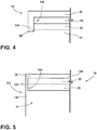
- the first attachment 126 is offset or misaligned from the second attachment 130. Stated differently, the first attachment 126 is separated from the second attachment 130. It is advantageous to offset or misalign the first and second attachments 126, 130 to increase the structural integrity of the adapter panel 26.
- the decorative panel 30 may include a border member 134 that extends vertically therefrom.
- the border member 134 extends from all or a portion of a perimeter of the decorative panel 30. In particular, the front and opposing sides of the perimeter of the decorative panel 30.
- the border member 134 extends downward towards the cabinet 14 and typically operates to conceal at least the adapter panel 26 and typically the structural panel 22 from the view of a consumer.
- the border member 134 defines a concealing cavity 136.
- the adapter panel 26, the structural panel 22, and/or at least a portion of the cabinet 14 are disposed within the concealing cavity 136 when the decorative panel 30 is assembled with the cabinet 14. In this way, the border member 134 conceals the adapter panel 26 and/or the structural panel 22.
- an end of the border member 134 aligns with and/or be disposed proximate to the top edge 68 of the cabinet 14.
- the border member 134 can increase the aesthetics of the laundry appliance 10 by concealing less decorative features (e.g., the structural panel 22 and/or the adapter panel 26) with the more aesthetic decorative panel 30.
- the border member 134 additionally conceals the first and second attachments 126, 130 ( FIG. 3 ) and therefore increase the aesthetics of the laundry appliance 10.
- the border member 134 aligns the adapter panel 26 and/or the structural panel 22. In this way, at least one of the adapter panel 26 and the structural panel 22 abuts the border member 134.
- the cabinet 14 may include a locating flange 138 that extends upwards from a side panel 142 of the cabinet 14.
- the cabinet 14 and the locating flange 138 form a second receiving cavity 144 proximate the top portion 124 of the laundry appliance 10.
- the locating flange 138 conceals the adapter panel 26 and/or the structural panel 22.
- the locating flange 138 conceals the first and second attachments 126, 130 ( FIG. 3 ). In this way, the locating flange 138 typically increases the aesthetics of the laundry appliance 10 by concealing less decorative features (e.g., the structural panel 22 and/orthe adapter panel 26).
- the locating flange 138 extends upward, such that an end of the locating flange 138 is typically disposed proximate the bottom surface 108 of the decorative panel 30. According to various aspects, the locating flange 138 abuts the bottom surface 108 of the decorative panel 30. In this way, the decorative panel 30 extends over the locating flange 138 to provide for a continuous appearance of the side panel 142 of the laundry appliance 10.
- the locating flange 138 may assist in aligning the structural panel 22 and/or the adapter panel 26, as well as, increase the aesthetics of the laundry appliance 10 by concealing the structural panel 22 and/or the adapter panel 26. Additionally or alternatively, in various examples, a sealant may be positioned proximate the locating flange 138 to prevent the infiltration of water into the cabinet 14.
- one goal of the present disclosure is to provide for a laundry appliance 10 that can be located within a common area or within a smaller residence that may not include a dedicated laundry or utility room.
- the decorative panel 30 can be selectively coupled to the adapter panel 26 and can provide a consumer with the ability to disguise or conceal the laundry appliance 10.
- the decorative panel 30 can be customizable by the consumer. In this way, the appearance of the laundry appliance 10 can be customizable to the consumer.
- the decorative panel 30 can be selectively coupled to the laundry appliance 10. As such, the consumer can uncouple the decorative panel 30 and couple a different decorative panel 30 to the laundry appliance 10 to change the appearance of the laundry appliance 10.
- the decorative panel 30 is typically removed for shipping of the laundry appliance 10, which can be advantageous for reducing damage during the shipping process.
- the structural panel 22 and the adapter panel 26, by having a separate attachment 130 can be installed on the appliance 10 to remain in place for the life of the appliance 10.
- the decorative panel 30, because of the separate attachment points 126, can be installed, removed, replaced, and reinstalled without disturbing the integrity of the structural and adapter panels 22, 26.
- the adapter panel 26 also provides a cushioned or flexible surface upon which the decorative panel 30 can be placed to minimize the changes of denting, scratching, or other damage to the cabinet 14. Additional benefits and advantages of using this device may also be realized and/or achieved.
- a laundry appliance includes a cabinet including a top edge.
- a structural panel is attached to the top edge of the cabinet.
- An adapter panel is attached to the structural panel.
- the adapter panel extends over at least a portion of an upper surface of the structural panel.
- a decorative panel is removably coupled to the adapter panel.
- the decorative panel is disposed over a top surface of the adapter panel. The decorative panel is free of attachment with the cabinet.
- a cabinet includes a locating flange that extends vertically upward from a top edge to align a structural panel with a top edge of the cabinet.
- an end of a locating flange aligns with a bottom surface of a decorative panel when a decorative panel is assembled with a cabinet.
- a decorative panel includes at least one snap feature that extends from a bottom surface thereof to couple to the adapter panel.
- a decorative panel includes a border member that extends from at least a portion of a perimeter toward a cabinet when the decorative panel is assembled on the cabinet.
- the border member defines a concealing cavity.
- an adapter panel and at least a portion of a cabinet are disposed in a concealing cavity when assembled.
- a decorative panel includes at least one of a design, a pattern, wording, and artwork.
- a laundry appliance includes a cabinet that defines an opening and includes a top edge.
- a door is coupled to the cabinet and is operable between opened and closed positions relative to the opening.
- a structural panel is attached to the top edge of the cabinet.
- the structural panel defines at least one aperture for receiving a coupling member.
- An adapter panel is coupled to an upper surface of the structural panel.
- the adapter panel defines at least one receiving hole for receiving the coupling member.
- a decorative panel is disposed on a top surface of the adapter panel.
- a decorative panel has a length and a width greater than a length and a width of an adapter panel.
- a decorative panel defines at least one recess for receiving a coupling member.
- At least one decorative inlay is disposed in at least one recess.
- a decorative panel includes a border member that extends from at least a portion of a perimeter toward a cabinet when the decorative panel is assembled with the cabinet.
- At least one of an adapter panel and a structural panel abuts a border member of the decorative panel.
- an end of the border member aligns with the top edge of the cabinet when a decorative panel is assembled with the cabinet.
- a decorative panel assembly for a laundry appliance includes a structural panel that defines a top panel of a cabinet.
- An adapter panel is coupled to the structural panel and forms a first attachment therebetween.
- the adapter panel extends over at least a substantial portion of an upper surface of the structural panel.
- a decorative panel is selectively coupled to the adapter panel and forms a second attachment therebetween.
- the decorative panel extends over a top surface of the adapter panel.
- the decorative panel is selectively removable from the adapter panel.
- the first attachment is separated from the second attachment.
- a first attachment is defined by a coupling member that extends through a recess defined by the decorative panel and a receiving hole defined by the adapter panel.
- a decorative inlay is disposed within a recess forming a continuous outer top surface of a decorative panel.
- a second attachment is defined by a coupling member that extends through a receiving hole defined by an adapter panel and an aperture defined by a structural panel.
- first and second attachments are offset from one another.
- a decorative panel has a length and a width greater than a length and a width of an adapter panel.
Landscapes
- Engineering & Computer Science (AREA)
- Textile Engineering (AREA)
- Detail Structures Of Washing Machines And Dryers (AREA)
- Main Body Construction Of Washing Machines And Laundry Dryers (AREA)
Claims (14)
- Frontlader-Wäschebehandlungsmaschine (10), einschließlich einer Dekorplattenanordnung für eine Wäschebehandlungsmaschine (10), umfassend:eine Strukturplatte (22), die eine Obere Platte eines Gehäuses (14) definiert;eine Adapterplatte (26), die an die Strukturplatte (22) gekoppelt ist und dazwischen ein erstes Befestigungselement (126) bildet, wobei sich die Adapterplatte (26) über mindestens einen wesentlichen Abschnitt einer Oberseite (94) der Strukturplatte (22) erstreckt; undeine Dekorplatte (30), die selektiv an die Adapterplatte (26) gekoppelt ist und dazwischen ein zweites Befestigungselement (130) bildet, wobei sich die Dekorplatte (30) über eine obere Oberfläche (122) der Adapterplatte (26) erstreckt und wobei die Dekorplatte (30) selektiv von der Adapterplatte (26) entfernbar ist und wobei das erste Befestigungselement (126) von dem zweiten Befestigungselement (130) getrennt ist.
- Frontlader-Wäschebehandlungsmaschine nach Anspruch 1, wobei das erste Befestigungselement (126) durch ein Kopplungselement (86) definiert ist, das sich durch eine Aussparung (114), die durch die Dekorplatte (30) definiert ist, und ein Aufnahmeloch (106), das durch die Adapterplatte (26) definiert ist, erstreckt.
- Frontlader-Wäschebehandlungsmaschine nach Anspruch 2, weiter umfassend: eine Dekoreinlage (118), die innerhalb der Aussparung (114) angeordnet ist und eine durchgehende äußere Oberfläche (120) der Dekorplatte (30) bildet.
- Frontlader-Wäschebehandlungsmaschine nach einem der Ansprüche 1-3, wobei das zweite Befestigungselement (130) durch ein Kopplungselement (86) definiert ist, das sich durch ein Aufnahmeloch (106), das durch die Adapterplatte (26) definiert ist, und eine Öffnung (74), die durch die Strukturplatte (22) definiert ist, erstreckt.
- Frontlader-Wäschebehandlungsmaschine nach einem der Ansprüche 1-4, wobei das erste und das zweite Befestigungselement (126, 130) gegeneinander versetzt sind.
- Frontlader-Wäschebehandlungsmaschine nach einem der Ansprüche 1-5, wobei die Dekorplatte (30) eine Länge und eine Breite aufweist, die größer als eine Länge und eine Breite der Adapterplatte (26) ist.
- Frontlader-Wäschebehandlungsmaschine nach einem der Ansprüche 1-6, wobei die Dekorplatte (30) mindestens ein Schnappmerkmal (86) einschließt, das sich von einer Unterseite (108) davon zum Koppeln an die Adapterplatte (26) erstreckt.
- Frontlader-Wäschebehandlungsmaschine nach einem der Ansprüche 1-7, wobei die Dekorplatte (30) mindestens eines von einem Design, einer Beschriftung, einer Grafik und einem Muster einschließt.
- Frontlader-Wäschebehandlungsmaschine nach einem der Ansprüche 1-8, wobei die Dekorplatte (30) ein Randelement (134) einschließt, das sich von mindestens einem Abschnitt eines Umfangs in Richtung des Gehäuses (14) erstreckt, wenn die Dekorplatte (30) an dem Gehäuse (14) montiert ist, und wobei das Randelement (134) einen Verdeckungshohlraum (136) definiert.
- Frontlader-Wäschebehandlungsmaschine nach Anspruch 9, wobei mindestens eine von der Adapterplatte (26) und der Strukturplatte (22) an das Randelement (134) der Dekorplatte (30) stößt.
- Frontlader-Wäschebehandlungsmaschine nach Anspruch 9, wobei ein Ende des Randelements (134) an einer Oberkante (68) des Gehäuses (14) ausgerichtet ist, wenn die Dekorplatte (30) an dem Gehäuse (14) montiert ist.
- Frontlader-Wäschebehandlungsmaschine nach einem der Ansprüche 1-8, wobei das Gehäuse (14) einen Positionierflansch (138) einschließt, der sich vertikal nach oben von einer Oberkante (68) erstreckt, um die Strukturplatte (22) an der Oberkante (68) des Gehäuses (14) auszurichten.
- Frontlader-Wäschebehandlungsmaschine nach Anspruch 12, wobei ein Ende des Positionierflanschs (138) an einer Unterseite (108) der Dekorplatte (30) ausgerichtet ist, wenn die Dekorplatte (30) an dem Gehäuse (14) montiert ist.
- Frontlader-Wäschebehandlungsmaschine nach einem der Ansprüche 1-13, wobei die Dekorplatte (30) keine Befestigung an dem Gehäuse (14) aufweist.
Applications Claiming Priority (2)
| Application Number | Priority Date | Filing Date | Title |
|---|---|---|---|
| US201862786095P | 2018-12-28 | 2018-12-28 | |
| US16/597,118 US11083296B2 (en) | 2018-12-28 | 2019-10-09 | Top attachment for a laundry appliance |
Publications (2)
| Publication Number | Publication Date |
|---|---|
| EP3674473A1 EP3674473A1 (de) | 2020-07-01 |
| EP3674473B1 true EP3674473B1 (de) | 2021-09-15 |
Family
ID=68342727
Family Applications (1)
| Application Number | Title | Priority Date | Filing Date |
|---|---|---|---|
| EP19204973.2A Not-in-force EP3674473B1 (de) | 2018-12-28 | 2019-10-23 | Ein frontlader-waschgerät mit einer dekorativen plattenanordnung für ein waschgerät |
Country Status (2)
| Country | Link |
|---|---|
| US (2) | US11083296B2 (de) |
| EP (1) | EP3674473B1 (de) |
Cited By (1)
| Publication number | Priority date | Publication date | Assignee | Title |
|---|---|---|---|---|
| DE102021133995A1 (de) | 2021-12-21 | 2023-06-22 | Paul Hettich Gmbh & Co. Kg | Drehelement, Möbel und Verfahren zur Positionierung eines Translations-Rotations-Beschlags eines Drehelements |
Families Citing this family (3)
| Publication number | Priority date | Publication date | Assignee | Title |
|---|---|---|---|---|
| DE102018107419A1 (de) * | 2018-03-28 | 2019-10-02 | Bulthaup Gmbh & Co. Kg | Möbelplatte |
| DE102021117357A1 (de) * | 2021-07-06 | 2023-01-12 | Miele & Cie. Kg | Deckel für eine Wäschebehandlungsmaschine und Wäschebehandlungsmaschine |
| IL287055B2 (en) * | 2021-10-06 | 2025-09-01 | Keter Home & Garden Products Ltd | Reinforced structure and method for strengthening it |
Family Cites Families (48)
| Publication number | Priority date | Publication date | Assignee | Title |
|---|---|---|---|---|
| US3610175A (en) * | 1969-06-05 | 1971-10-05 | Wilton Brass Co | Plaquelike covering members for serving pieces |
| US3820296A (en) * | 1973-01-16 | 1974-06-28 | Westinghouse Electric Corp | Panel and trim assembly |
| US4073556A (en) * | 1976-09-21 | 1978-02-14 | H. Wilson Corporation | Rigid mobile cabinet for audio-visual aids |
| US4143496A (en) * | 1977-12-09 | 1979-03-13 | Joseph Destito | Wall decorating device |
| IT7934040U1 (it) | 1979-12-10 | 1981-06-10 | Zanussi A Spa Industrie | Macchina lavatrice con piano di lavoro regolabile. |
| US5249857A (en) * | 1989-10-30 | 1993-10-05 | Kyoraku Co., Ltd. | Built-up furniture unit |
| IT1246499B (it) | 1989-12-11 | 1994-11-19 | Bosch Siemens Hausgeraete | Coperchio della cassa per una macchina per uso domestico |
| US5176435A (en) * | 1990-11-19 | 1993-01-05 | Interchangeable Design Systems, Inc. | Interchangeable modular furniture system |
| FR2673575A1 (fr) | 1991-03-06 | 1992-09-11 | So Ge Ma P | Piece comprenant un corps en matiere thermoplastique recouvert sur une face d'un papier decor melamine, et procede de fabrication d'une telle piece. |
| DE4240888C3 (de) | 1992-12-04 | 2000-10-26 | Juergen Schildberg | Abdeckplatte |
| US5590500A (en) * | 1993-10-20 | 1997-01-07 | Mccue; David L. | Tile system |
| US5546873A (en) * | 1994-10-28 | 1996-08-20 | Steelcase Inc. | Furniture worksurface unit and method |
| DE29606891U1 (de) * | 1996-04-16 | 1996-08-29 | Bosch-Siemens Hausgeräte GmbH, 81669 München | Haushaltgerät |
| DE19750946B4 (de) | 1997-04-24 | 2011-04-28 | BSH Bosch und Siemens Hausgeräte GmbH | Arbeitsplatte für schrankförmige Haushaltsgeräte |
| US5941617A (en) * | 1997-11-14 | 1999-08-24 | The Panda Project | Decorative panel for computer enclosure |
| US6086174A (en) * | 1998-01-21 | 2000-07-11 | Graves; William B. | Appliance cabinet with removable panels |
| US5983808A (en) | 1998-02-09 | 1999-11-16 | Weil; Louis | Shelving system for concealing an appliance |
| US6113203A (en) * | 1999-07-01 | 2000-09-05 | Chen; Kuen Jen | Tool box assembly |
| DE19940145A1 (de) * | 1999-08-25 | 2001-03-01 | Targor Gmbh | Abdeckplatte für Haushaltsgeräte |
| US20030222547A1 (en) * | 2002-05-28 | 2003-12-04 | Kathleen Trees | Interchangeable cabinetware |
| KR100406163B1 (en) * | 2003-07-03 | 2003-11-19 | Byung Mo Yoon | Decoration panel |
| US20070151306A1 (en) * | 2005-12-30 | 2007-07-05 | Gilboe Kevin J | Modular laundry system with work surface |
| DE102005057509A1 (de) * | 2004-12-27 | 2006-07-13 | Personal & Original, S.L. | Schutz- und Zierplatte für Haushaltsgeräte |
| AU2006221219B2 (en) * | 2005-03-08 | 2009-12-03 | Lg Electronics, Inc. | Washing machine |
| US20060219693A1 (en) * | 2005-03-17 | 2006-10-05 | Advance Distribution Services, Inc. | Personalized appliance and method of making the same |
| KR101234064B1 (ko) | 2005-04-15 | 2013-02-15 | 엘지전자 주식회사 | 세탁기 |
| WO2007011774A2 (en) * | 2005-07-14 | 2007-01-25 | Master Lock Company Llc | Interchangeable face plate |
| US20070022921A1 (en) * | 2005-07-27 | 2007-02-01 | Perkins Travis M | Storage and work system |
| ES2311360B1 (es) | 2006-07-07 | 2009-12-02 | Bsh Electrodomesticos España, S.A. | Aparato electrodomestico. |
| KR101368290B1 (ko) * | 2007-03-08 | 2014-02-26 | 삼성전자주식회사 | 세탁기 |
| DE102008019421A1 (de) * | 2008-04-17 | 2009-10-22 | BSH Bosch und Siemens Hausgeräte GmbH | Beschlagaufbau und Verfahren zur höhenrichtigen Montage einer Dekorplatte an einer Tür eines Haushaltsgeräts |
| EP2181830A1 (de) | 2008-10-31 | 2010-05-05 | GRUSAN S.r.l. | Herstellungsverfahren für eine Arbeitsplatte, insbesondere für Haushaltsanwendungen, und so hergestellte Arbeitsplatte |
| US8474193B2 (en) * | 2009-03-05 | 2013-07-02 | Raspberry Med, Inc. | Wall-mounted modular accessory system |
| US9387912B2 (en) * | 2009-10-09 | 2016-07-12 | Driessen Aircraft Interior Systems, Inc. | Panel inserts for aircraft and other vessels |
| IT1399435B1 (it) * | 2010-04-13 | 2013-04-19 | Gatto S P A | Anta per mobili con pannello amovibile - intercambiabile. |
| US8870306B2 (en) * | 2010-12-29 | 2014-10-28 | Lee Simon | Hospitality environment item and method of assembly |
| JP5659842B2 (ja) | 2011-02-16 | 2015-01-28 | パナソニックIpマネジメント株式会社 | ドラム式洗濯機 |
| CN202559124U (zh) | 2011-11-23 | 2012-11-28 | 龚银其 | 带有图案层的洗衣机 |
| US20130337220A1 (en) * | 2012-06-13 | 2013-12-19 | Ashley Furniture Industries, Inc. | Furniture article with interchangeable panel set |
| US9185981B1 (en) * | 2014-08-25 | 2015-11-17 | Richardson Industries, Inc. | Cabinetry system having removable cabinet faces |
| CN107105895B (zh) * | 2014-10-31 | 2020-07-28 | 庞巴迪公司 | 具有可拆离外板和所用的附接机构的飞机机柜 |
| US20160235201A1 (en) * | 2015-02-13 | 2016-08-18 | Anneli Sööt | Interchangeable Facing For Cabinetry |
| CN204825390U (zh) | 2015-06-18 | 2015-12-02 | 无锡小天鹅股份有限公司 | 用于洗衣机的门盖组件和洗衣机 |
| US20170156499A1 (en) * | 2015-12-04 | 2017-06-08 | Richardson Industries, Inc. | Cabinetry system having removable cabinet faces and reversible inserts |
| CN107587313B (zh) * | 2016-07-07 | 2020-08-21 | Lg电子株式会社 | 洗涤物处理装置 |
| CN108797053B (zh) | 2017-04-28 | 2021-10-22 | 青岛海尔洗衣机有限公司 | 一种干衣机盘座及干衣机 |
| US10470641B2 (en) * | 2017-08-21 | 2019-11-12 | Whirlpool Corporation | Dishwasher having a decorative panel |
| CN110847306B (zh) * | 2018-08-21 | 2022-09-27 | 科勒公司 | 带有可互换面的前裙板水槽 |
-
2019
- 2019-10-09 US US16/597,118 patent/US11083296B2/en not_active Expired - Fee Related
- 2019-10-23 EP EP19204973.2A patent/EP3674473B1/de not_active Not-in-force
-
2021
- 2021-06-29 US US17/362,340 patent/US11647837B2/en active Active
Cited By (1)
| Publication number | Priority date | Publication date | Assignee | Title |
|---|---|---|---|---|
| DE102021133995A1 (de) | 2021-12-21 | 2023-06-22 | Paul Hettich Gmbh & Co. Kg | Drehelement, Möbel und Verfahren zur Positionierung eines Translations-Rotations-Beschlags eines Drehelements |
Also Published As
| Publication number | Publication date |
|---|---|
| US11647837B2 (en) | 2023-05-16 |
| US20210321771A1 (en) | 2021-10-21 |
| US20200205569A1 (en) | 2020-07-02 |
| US11083296B2 (en) | 2021-08-10 |
| EP3674473A1 (de) | 2020-07-01 |
Similar Documents
| Publication | Publication Date | Title |
|---|---|---|
| US11647837B2 (en) | Top attachment for a laundry appliance | |
| US5496104A (en) | Outer decorative door assembly for domestic appliances | |
| KR101256218B1 (ko) | 도어용 잼 어셈블리 | |
| US6637073B2 (en) | Hinge cover | |
| USD516082S1 (en) | Music system | |
| WO2007131903A3 (de) | Zusatzelement für ein möbelteil aus einer leichtbauplatte, möbelteil und möbel | |
| USD541764S1 (en) | Mounting panel and audio-video assembly for suspension on a wall surface | |
| USD492141S1 (en) | Cabinet panel | |
| US7766436B1 (en) | Appliance panel with overlay panel and a method for mounting an overlay panel to an appliance panel | |
| USD529431S1 (en) | Leather bag lid liner and support panel | |
| JP5719156B2 (ja) | 異種材料キャビネット | |
| KR200406672Y1 (ko) | 테두리 마감부재가 구비된 가구용 도어 | |
| JP2009219735A (ja) | 幕板 | |
| JP2001321529A (ja) | 遊技機 | |
| EP0080770B1 (de) | Tür für eine Wasch- und/oder Trockenmaschine | |
| USD553967S1 (en) | Patio door panel upper left hand corner bracket connector | |
| KR20010088040A (ko) | 방화문 | |
| JPH0593583A (ja) | 冷蔵庫 | |
| JP3073007U (ja) | 改良化粧コーナー保護材 | |
| KR200405510Y1 (ko) | 장식몰딩이 장착된 화장실 칸막이구조 | |
| USD553484S1 (en) | Patio door panel upper left hand corner bracket connector | |
| JP2008206930A (ja) | キャビネット構造 | |
| JP2507025Y2 (ja) | 浴槽のエプロンの構造 | |
| JP2006248014A (ja) | 化粧部材 | |
| JP2021013456A (ja) | 洗面化粧台および洗面化粧台の施工方法 |
Legal Events
| Date | Code | Title | Description |
|---|---|---|---|
| PUAI | Public reference made under article 153(3) epc to a published international application that has entered the european phase |
Free format text: ORIGINAL CODE: 0009012 |
|
| STAA | Information on the status of an ep patent application or granted ep patent |
Free format text: STATUS: THE APPLICATION HAS BEEN PUBLISHED |
|
| AK | Designated contracting states |
Kind code of ref document: A1 Designated state(s): AL AT BE BG CH CY CZ DE DK EE ES FI FR GB GR HR HU IE IS IT LI LT LU LV MC MK MT NL NO PL PT RO RS SE SI SK SM TR |
|
| AX | Request for extension of the european patent |
Extension state: BA ME |
|
| STAA | Information on the status of an ep patent application or granted ep patent |
Free format text: STATUS: REQUEST FOR EXAMINATION WAS MADE |
|
| 17P | Request for examination filed |
Effective date: 20201202 |
|
| RBV | Designated contracting states (corrected) |
Designated state(s): AL AT BE BG CH CY CZ DE DK EE ES FI FR GB GR HR HU IE IS IT LI LT LU LV MC MK MT NL NO PL PT RO RS SE SI SK SM TR |
|
| GRAP | Despatch of communication of intention to grant a patent |
Free format text: ORIGINAL CODE: EPIDOSNIGR1 |
|
| STAA | Information on the status of an ep patent application or granted ep patent |
Free format text: STATUS: GRANT OF PATENT IS INTENDED |
|
| INTG | Intention to grant announced |
Effective date: 20210618 |
|
| GRAS | Grant fee paid |
Free format text: ORIGINAL CODE: EPIDOSNIGR3 |
|
| GRAA | (expected) grant |
Free format text: ORIGINAL CODE: 0009210 |
|
| STAA | Information on the status of an ep patent application or granted ep patent |
Free format text: STATUS: THE PATENT HAS BEEN GRANTED |
|
| AK | Designated contracting states |
Kind code of ref document: B1 Designated state(s): AL AT BE BG CH CY CZ DE DK EE ES FI FR GB GR HR HU IE IS IT LI LT LU LV MC MK MT NL NO PL PT RO RS SE SI SK SM TR |
|
| REG | Reference to a national code |
Ref country code: CH Ref legal event code: EP |
|
| REG | Reference to a national code |
Ref country code: DE Ref legal event code: R096 Ref document number: 602019007698 Country of ref document: DE |
|
| REG | Reference to a national code |
Ref country code: IE Ref legal event code: FG4D |
|
| REG | Reference to a national code |
Ref country code: AT Ref legal event code: REF Ref document number: 1430602 Country of ref document: AT Kind code of ref document: T Effective date: 20211015 |
|
| REG | Reference to a national code |
Ref country code: LT Ref legal event code: MG9D |
|
| REG | Reference to a national code |
Ref country code: NL Ref legal event code: MP Effective date: 20210915 |
|
| PG25 | Lapsed in a contracting state [announced via postgrant information from national office to epo] |
Ref country code: BG Free format text: LAPSE BECAUSE OF FAILURE TO SUBMIT A TRANSLATION OF THE DESCRIPTION OR TO PAY THE FEE WITHIN THE PRESCRIBED TIME-LIMIT Effective date: 20211215 Ref country code: LT Free format text: LAPSE BECAUSE OF FAILURE TO SUBMIT A TRANSLATION OF THE DESCRIPTION OR TO PAY THE FEE WITHIN THE PRESCRIBED TIME-LIMIT Effective date: 20210915 Ref country code: NO Free format text: LAPSE BECAUSE OF FAILURE TO SUBMIT A TRANSLATION OF THE DESCRIPTION OR TO PAY THE FEE WITHIN THE PRESCRIBED TIME-LIMIT Effective date: 20211215 Ref country code: HR Free format text: LAPSE BECAUSE OF FAILURE TO SUBMIT A TRANSLATION OF THE DESCRIPTION OR TO PAY THE FEE WITHIN THE PRESCRIBED TIME-LIMIT Effective date: 20210915 Ref country code: FI Free format text: LAPSE BECAUSE OF FAILURE TO SUBMIT A TRANSLATION OF THE DESCRIPTION OR TO PAY THE FEE WITHIN THE PRESCRIBED TIME-LIMIT Effective date: 20210915 Ref country code: SE Free format text: LAPSE BECAUSE OF FAILURE TO SUBMIT A TRANSLATION OF THE DESCRIPTION OR TO PAY THE FEE WITHIN THE PRESCRIBED TIME-LIMIT Effective date: 20210915 Ref country code: RS Free format text: LAPSE BECAUSE OF FAILURE TO SUBMIT A TRANSLATION OF THE DESCRIPTION OR TO PAY THE FEE WITHIN THE PRESCRIBED TIME-LIMIT Effective date: 20210915 |
|
| REG | Reference to a national code |
Ref country code: AT Ref legal event code: MK05 Ref document number: 1430602 Country of ref document: AT Kind code of ref document: T Effective date: 20210915 |
|
| PG25 | Lapsed in a contracting state [announced via postgrant information from national office to epo] |
Ref country code: LV Free format text: LAPSE BECAUSE OF FAILURE TO SUBMIT A TRANSLATION OF THE DESCRIPTION OR TO PAY THE FEE WITHIN THE PRESCRIBED TIME-LIMIT Effective date: 20210915 Ref country code: GR Free format text: LAPSE BECAUSE OF FAILURE TO SUBMIT A TRANSLATION OF THE DESCRIPTION OR TO PAY THE FEE WITHIN THE PRESCRIBED TIME-LIMIT Effective date: 20211216 |
|
| PG25 | Lapsed in a contracting state [announced via postgrant information from national office to epo] |
Ref country code: AT Free format text: LAPSE BECAUSE OF FAILURE TO SUBMIT A TRANSLATION OF THE DESCRIPTION OR TO PAY THE FEE WITHIN THE PRESCRIBED TIME-LIMIT Effective date: 20210915 |
|
| PG25 | Lapsed in a contracting state [announced via postgrant information from national office to epo] |
Ref country code: IS Free format text: LAPSE BECAUSE OF FAILURE TO SUBMIT A TRANSLATION OF THE DESCRIPTION OR TO PAY THE FEE WITHIN THE PRESCRIBED TIME-LIMIT Effective date: 20220115 Ref country code: SM Free format text: LAPSE BECAUSE OF FAILURE TO SUBMIT A TRANSLATION OF THE DESCRIPTION OR TO PAY THE FEE WITHIN THE PRESCRIBED TIME-LIMIT Effective date: 20210915 Ref country code: SK Free format text: LAPSE BECAUSE OF FAILURE TO SUBMIT A TRANSLATION OF THE DESCRIPTION OR TO PAY THE FEE WITHIN THE PRESCRIBED TIME-LIMIT Effective date: 20210915 Ref country code: RO Free format text: LAPSE BECAUSE OF FAILURE TO SUBMIT A TRANSLATION OF THE DESCRIPTION OR TO PAY THE FEE WITHIN THE PRESCRIBED TIME-LIMIT Effective date: 20210915 Ref country code: PT Free format text: LAPSE BECAUSE OF FAILURE TO SUBMIT A TRANSLATION OF THE DESCRIPTION OR TO PAY THE FEE WITHIN THE PRESCRIBED TIME-LIMIT Effective date: 20220117 Ref country code: PL Free format text: LAPSE BECAUSE OF FAILURE TO SUBMIT A TRANSLATION OF THE DESCRIPTION OR TO PAY THE FEE WITHIN THE PRESCRIBED TIME-LIMIT Effective date: 20210915 Ref country code: NL Free format text: LAPSE BECAUSE OF FAILURE TO SUBMIT A TRANSLATION OF THE DESCRIPTION OR TO PAY THE FEE WITHIN THE PRESCRIBED TIME-LIMIT Effective date: 20210915 Ref country code: ES Free format text: LAPSE BECAUSE OF FAILURE TO SUBMIT A TRANSLATION OF THE DESCRIPTION OR TO PAY THE FEE WITHIN THE PRESCRIBED TIME-LIMIT Effective date: 20210915 Ref country code: EE Free format text: LAPSE BECAUSE OF FAILURE TO SUBMIT A TRANSLATION OF THE DESCRIPTION OR TO PAY THE FEE WITHIN THE PRESCRIBED TIME-LIMIT Effective date: 20210915 Ref country code: CZ Free format text: LAPSE BECAUSE OF FAILURE TO SUBMIT A TRANSLATION OF THE DESCRIPTION OR TO PAY THE FEE WITHIN THE PRESCRIBED TIME-LIMIT Effective date: 20210915 Ref country code: AL Free format text: LAPSE BECAUSE OF FAILURE TO SUBMIT A TRANSLATION OF THE DESCRIPTION OR TO PAY THE FEE WITHIN THE PRESCRIBED TIME-LIMIT Effective date: 20210915 |
|
| REG | Reference to a national code |
Ref country code: DE Ref legal event code: R097 Ref document number: 602019007698 Country of ref document: DE |
|
| REG | Reference to a national code |
Ref country code: BE Ref legal event code: MM Effective date: 20211031 |
|
| PG25 | Lapsed in a contracting state [announced via postgrant information from national office to epo] |
Ref country code: MC Free format text: LAPSE BECAUSE OF FAILURE TO SUBMIT A TRANSLATION OF THE DESCRIPTION OR TO PAY THE FEE WITHIN THE PRESCRIBED TIME-LIMIT Effective date: 20210915 |
|
| PLBE | No opposition filed within time limit |
Free format text: ORIGINAL CODE: 0009261 |
|
| STAA | Information on the status of an ep patent application or granted ep patent |
Free format text: STATUS: NO OPPOSITION FILED WITHIN TIME LIMIT |
|
| PG25 | Lapsed in a contracting state [announced via postgrant information from national office to epo] |
Ref country code: LU Free format text: LAPSE BECAUSE OF NON-PAYMENT OF DUE FEES Effective date: 20211023 Ref country code: DK Free format text: LAPSE BECAUSE OF FAILURE TO SUBMIT A TRANSLATION OF THE DESCRIPTION OR TO PAY THE FEE WITHIN THE PRESCRIBED TIME-LIMIT Effective date: 20210915 Ref country code: BE Free format text: LAPSE BECAUSE OF NON-PAYMENT OF DUE FEES Effective date: 20211031 |
|
| 26N | No opposition filed |
Effective date: 20220616 |
|
| PG25 | Lapsed in a contracting state [announced via postgrant information from national office to epo] |
Ref country code: SI Free format text: LAPSE BECAUSE OF FAILURE TO SUBMIT A TRANSLATION OF THE DESCRIPTION OR TO PAY THE FEE WITHIN THE PRESCRIBED TIME-LIMIT Effective date: 20210915 |
|
| PG25 | Lapsed in a contracting state [announced via postgrant information from national office to epo] |
Ref country code: IE Free format text: LAPSE BECAUSE OF NON-PAYMENT OF DUE FEES Effective date: 20211023 |
|
| REG | Reference to a national code |
Ref country code: CH Ref legal event code: PL |
|
| P01 | Opt-out of the competence of the unified patent court (upc) registered |
Effective date: 20230522 |
|
| PG25 | Lapsed in a contracting state [announced via postgrant information from national office to epo] |
Ref country code: CY Free format text: LAPSE BECAUSE OF FAILURE TO SUBMIT A TRANSLATION OF THE DESCRIPTION OR TO PAY THE FEE WITHIN THE PRESCRIBED TIME-LIMIT Effective date: 20210915 |
|
| PG25 | Lapsed in a contracting state [announced via postgrant information from national office to epo] |
Ref country code: LI Free format text: LAPSE BECAUSE OF NON-PAYMENT OF DUE FEES Effective date: 20221031 Ref country code: HU Free format text: LAPSE BECAUSE OF FAILURE TO SUBMIT A TRANSLATION OF THE DESCRIPTION OR TO PAY THE FEE WITHIN THE PRESCRIBED TIME-LIMIT; INVALID AB INITIO Effective date: 20191023 Ref country code: CH Free format text: LAPSE BECAUSE OF NON-PAYMENT OF DUE FEES Effective date: 20221031 |
|
| PGFP | Annual fee paid to national office [announced via postgrant information from national office to epo] |
Ref country code: GB Payment date: 20231024 Year of fee payment: 5 |
|
| PGFP | Annual fee paid to national office [announced via postgrant information from national office to epo] |
Ref country code: IT Payment date: 20231024 Year of fee payment: 5 Ref country code: FR Payment date: 20231026 Year of fee payment: 5 Ref country code: DE Payment date: 20231027 Year of fee payment: 5 |
|
| PG25 | Lapsed in a contracting state [announced via postgrant information from national office to epo] |
Ref country code: MK Free format text: LAPSE BECAUSE OF FAILURE TO SUBMIT A TRANSLATION OF THE DESCRIPTION OR TO PAY THE FEE WITHIN THE PRESCRIBED TIME-LIMIT Effective date: 20210915 |
|
| PG25 | Lapsed in a contracting state [announced via postgrant information from national office to epo] |
Ref country code: TR Free format text: LAPSE BECAUSE OF FAILURE TO SUBMIT A TRANSLATION OF THE DESCRIPTION OR TO PAY THE FEE WITHIN THE PRESCRIBED TIME-LIMIT Effective date: 20210915 |
|
| PG25 | Lapsed in a contracting state [announced via postgrant information from national office to epo] |
Ref country code: MT Free format text: LAPSE BECAUSE OF FAILURE TO SUBMIT A TRANSLATION OF THE DESCRIPTION OR TO PAY THE FEE WITHIN THE PRESCRIBED TIME-LIMIT Effective date: 20210915 |
|
| REG | Reference to a national code |
Ref country code: DE Ref legal event code: R119 Ref document number: 602019007698 Country of ref document: DE |
|
| GBPC | Gb: european patent ceased through non-payment of renewal fee |
Effective date: 20241023 |
|
| PG25 | Lapsed in a contracting state [announced via postgrant information from national office to epo] |
Ref country code: DE Free format text: LAPSE BECAUSE OF NON-PAYMENT OF DUE FEES Effective date: 20250501 |
|
| PG25 | Lapsed in a contracting state [announced via postgrant information from national office to epo] |
Ref country code: GB Free format text: LAPSE BECAUSE OF NON-PAYMENT OF DUE FEES Effective date: 20241023 |
|
| PG25 | Lapsed in a contracting state [announced via postgrant information from national office to epo] |
Ref country code: FR Free format text: LAPSE BECAUSE OF NON-PAYMENT OF DUE FEES Effective date: 20241031 |
|
| PG25 | Lapsed in a contracting state [announced via postgrant information from national office to epo] |
Ref country code: IT Free format text: LAPSE BECAUSE OF NON-PAYMENT OF DUE FEES Effective date: 20241023 |