EP3674131A1 - Auxiliary battery accommodating device for electric vehicle - Google Patents
Auxiliary battery accommodating device for electric vehicle Download PDFInfo
- Publication number
- EP3674131A1 EP3674131A1 EP19766988.0A EP19766988A EP3674131A1 EP 3674131 A1 EP3674131 A1 EP 3674131A1 EP 19766988 A EP19766988 A EP 19766988A EP 3674131 A1 EP3674131 A1 EP 3674131A1
- Authority
- EP
- European Patent Office
- Prior art keywords
- auxiliary battery
- case body
- storage device
- body cover
- hooking
- Prior art date
- Legal status (The legal status is an assumption and is not a legal conclusion. Google has not performed a legal analysis and makes no representation as to the accuracy of the status listed.)
- Granted
Links
Images




Classifications
-
- B—PERFORMING OPERATIONS; TRANSPORTING
- B60—VEHICLES IN GENERAL
- B60L—PROPULSION OF ELECTRICALLY-PROPELLED VEHICLES; SUPPLYING ELECTRIC POWER FOR AUXILIARY EQUIPMENT OF ELECTRICALLY-PROPELLED VEHICLES; ELECTRODYNAMIC BRAKE SYSTEMS FOR VEHICLES IN GENERAL; MAGNETIC SUSPENSION OR LEVITATION FOR VEHICLES; MONITORING OPERATING VARIABLES OF ELECTRICALLY-PROPELLED VEHICLES; ELECTRIC SAFETY DEVICES FOR ELECTRICALLY-PROPELLED VEHICLES
- B60L58/00—Methods or circuit arrangements for monitoring or controlling batteries or fuel cells, specially adapted for electric vehicles
- B60L58/10—Methods or circuit arrangements for monitoring or controlling batteries or fuel cells, specially adapted for electric vehicles for monitoring or controlling batteries
- B60L58/18—Methods or circuit arrangements for monitoring or controlling batteries or fuel cells, specially adapted for electric vehicles for monitoring or controlling batteries of two or more battery modules
- B60L58/20—Methods or circuit arrangements for monitoring or controlling batteries or fuel cells, specially adapted for electric vehicles for monitoring or controlling batteries of two or more battery modules having different nominal voltages
-
- B—PERFORMING OPERATIONS; TRANSPORTING
- B60—VEHICLES IN GENERAL
- B60L—PROPULSION OF ELECTRICALLY-PROPELLED VEHICLES; SUPPLYING ELECTRIC POWER FOR AUXILIARY EQUIPMENT OF ELECTRICALLY-PROPELLED VEHICLES; ELECTRODYNAMIC BRAKE SYSTEMS FOR VEHICLES IN GENERAL; MAGNETIC SUSPENSION OR LEVITATION FOR VEHICLES; MONITORING OPERATING VARIABLES OF ELECTRICALLY-PROPELLED VEHICLES; ELECTRIC SAFETY DEVICES FOR ELECTRICALLY-PROPELLED VEHICLES
- B60L53/00—Methods of charging batteries, specially adapted for electric vehicles; Charging stations or on-board charging equipment therefor; Exchange of energy storage elements in electric vehicles
- B60L53/80—Exchanging energy storage elements, e.g. removable batteries
-
- B—PERFORMING OPERATIONS; TRANSPORTING
- B60—VEHICLES IN GENERAL
- B60K—ARRANGEMENT OR MOUNTING OF PROPULSION UNITS OR OF TRANSMISSIONS IN VEHICLES; ARRANGEMENT OR MOUNTING OF PLURAL DIVERSE PRIME-MOVERS IN VEHICLES; AUXILIARY DRIVES FOR VEHICLES; INSTRUMENTATION OR DASHBOARDS FOR VEHICLES; ARRANGEMENTS IN CONNECTION WITH COOLING, AIR INTAKE, GAS EXHAUST OR FUEL SUPPLY OF PROPULSION UNITS IN VEHICLES
- B60K1/00—Arrangement or mounting of electrical propulsion units
- B60K1/04—Arrangement or mounting of electrical propulsion units of the electric storage means for propulsion
-
- B—PERFORMING OPERATIONS; TRANSPORTING
- B60—VEHICLES IN GENERAL
- B60L—PROPULSION OF ELECTRICALLY-PROPELLED VEHICLES; SUPPLYING ELECTRIC POWER FOR AUXILIARY EQUIPMENT OF ELECTRICALLY-PROPELLED VEHICLES; ELECTRODYNAMIC BRAKE SYSTEMS FOR VEHICLES IN GENERAL; MAGNETIC SUSPENSION OR LEVITATION FOR VEHICLES; MONITORING OPERATING VARIABLES OF ELECTRICALLY-PROPELLED VEHICLES; ELECTRIC SAFETY DEVICES FOR ELECTRICALLY-PROPELLED VEHICLES
- B60L50/00—Electric propulsion with power supplied within the vehicle
- B60L50/50—Electric propulsion with power supplied within the vehicle using propulsion power supplied by batteries or fuel cells
-
- B—PERFORMING OPERATIONS; TRANSPORTING
- B60—VEHICLES IN GENERAL
- B60L—PROPULSION OF ELECTRICALLY-PROPELLED VEHICLES; SUPPLYING ELECTRIC POWER FOR AUXILIARY EQUIPMENT OF ELECTRICALLY-PROPELLED VEHICLES; ELECTRODYNAMIC BRAKE SYSTEMS FOR VEHICLES IN GENERAL; MAGNETIC SUSPENSION OR LEVITATION FOR VEHICLES; MONITORING OPERATING VARIABLES OF ELECTRICALLY-PROPELLED VEHICLES; ELECTRIC SAFETY DEVICES FOR ELECTRICALLY-PROPELLED VEHICLES
- B60L50/00—Electric propulsion with power supplied within the vehicle
- B60L50/50—Electric propulsion with power supplied within the vehicle using propulsion power supplied by batteries or fuel cells
- B60L50/60—Electric propulsion with power supplied within the vehicle using propulsion power supplied by batteries or fuel cells using power supplied by batteries
-
- B—PERFORMING OPERATIONS; TRANSPORTING
- B60—VEHICLES IN GENERAL
- B60L—PROPULSION OF ELECTRICALLY-PROPELLED VEHICLES; SUPPLYING ELECTRIC POWER FOR AUXILIARY EQUIPMENT OF ELECTRICALLY-PROPELLED VEHICLES; ELECTRODYNAMIC BRAKE SYSTEMS FOR VEHICLES IN GENERAL; MAGNETIC SUSPENSION OR LEVITATION FOR VEHICLES; MONITORING OPERATING VARIABLES OF ELECTRICALLY-PROPELLED VEHICLES; ELECTRIC SAFETY DEVICES FOR ELECTRICALLY-PROPELLED VEHICLES
- B60L50/00—Electric propulsion with power supplied within the vehicle
- B60L50/50—Electric propulsion with power supplied within the vehicle using propulsion power supplied by batteries or fuel cells
- B60L50/60—Electric propulsion with power supplied within the vehicle using propulsion power supplied by batteries or fuel cells using power supplied by batteries
- B60L50/64—Constructional details of batteries specially adapted for electric vehicles
-
- B—PERFORMING OPERATIONS; TRANSPORTING
- B60—VEHICLES IN GENERAL
- B60L—PROPULSION OF ELECTRICALLY-PROPELLED VEHICLES; SUPPLYING ELECTRIC POWER FOR AUXILIARY EQUIPMENT OF ELECTRICALLY-PROPELLED VEHICLES; ELECTRODYNAMIC BRAKE SYSTEMS FOR VEHICLES IN GENERAL; MAGNETIC SUSPENSION OR LEVITATION FOR VEHICLES; MONITORING OPERATING VARIABLES OF ELECTRICALLY-PROPELLED VEHICLES; ELECTRIC SAFETY DEVICES FOR ELECTRICALLY-PROPELLED VEHICLES
- B60L50/00—Electric propulsion with power supplied within the vehicle
- B60L50/50—Electric propulsion with power supplied within the vehicle using propulsion power supplied by batteries or fuel cells
- B60L50/60—Electric propulsion with power supplied within the vehicle using propulsion power supplied by batteries or fuel cells using power supplied by batteries
- B60L50/66—Arrangements of batteries
-
- B—PERFORMING OPERATIONS; TRANSPORTING
- B60—VEHICLES IN GENERAL
- B60L—PROPULSION OF ELECTRICALLY-PROPELLED VEHICLES; SUPPLYING ELECTRIC POWER FOR AUXILIARY EQUIPMENT OF ELECTRICALLY-PROPELLED VEHICLES; ELECTRODYNAMIC BRAKE SYSTEMS FOR VEHICLES IN GENERAL; MAGNETIC SUSPENSION OR LEVITATION FOR VEHICLES; MONITORING OPERATING VARIABLES OF ELECTRICALLY-PROPELLED VEHICLES; ELECTRIC SAFETY DEVICES FOR ELECTRICALLY-PROPELLED VEHICLES
- B60L53/00—Methods of charging batteries, specially adapted for electric vehicles; Charging stations or on-board charging equipment therefor; Exchange of energy storage elements in electric vehicles
- B60L53/10—Methods of charging batteries, specially adapted for electric vehicles; Charging stations or on-board charging equipment therefor; Exchange of energy storage elements in electric vehicles characterised by the energy transfer between the charging station and the vehicle
- B60L53/14—Conductive energy transfer
-
- B—PERFORMING OPERATIONS; TRANSPORTING
- B60—VEHICLES IN GENERAL
- B60L—PROPULSION OF ELECTRICALLY-PROPELLED VEHICLES; SUPPLYING ELECTRIC POWER FOR AUXILIARY EQUIPMENT OF ELECTRICALLY-PROPELLED VEHICLES; ELECTRODYNAMIC BRAKE SYSTEMS FOR VEHICLES IN GENERAL; MAGNETIC SUSPENSION OR LEVITATION FOR VEHICLES; MONITORING OPERATING VARIABLES OF ELECTRICALLY-PROPELLED VEHICLES; ELECTRIC SAFETY DEVICES FOR ELECTRICALLY-PROPELLED VEHICLES
- B60L53/00—Methods of charging batteries, specially adapted for electric vehicles; Charging stations or on-board charging equipment therefor; Exchange of energy storage elements in electric vehicles
- B60L53/10—Methods of charging batteries, specially adapted for electric vehicles; Charging stations or on-board charging equipment therefor; Exchange of energy storage elements in electric vehicles characterised by the energy transfer between the charging station and the vehicle
- B60L53/14—Conductive energy transfer
- B60L53/18—Cables specially adapted for charging electric vehicles
-
- B—PERFORMING OPERATIONS; TRANSPORTING
- B60—VEHICLES IN GENERAL
- B60L—PROPULSION OF ELECTRICALLY-PROPELLED VEHICLES; SUPPLYING ELECTRIC POWER FOR AUXILIARY EQUIPMENT OF ELECTRICALLY-PROPELLED VEHICLES; ELECTRODYNAMIC BRAKE SYSTEMS FOR VEHICLES IN GENERAL; MAGNETIC SUSPENSION OR LEVITATION FOR VEHICLES; MONITORING OPERATING VARIABLES OF ELECTRICALLY-PROPELLED VEHICLES; ELECTRIC SAFETY DEVICES FOR ELECTRICALLY-PROPELLED VEHICLES
- B60L58/00—Methods or circuit arrangements for monitoring or controlling batteries or fuel cells, specially adapted for electric vehicles
- B60L58/10—Methods or circuit arrangements for monitoring or controlling batteries or fuel cells, specially adapted for electric vehicles for monitoring or controlling batteries
- B60L58/12—Methods or circuit arrangements for monitoring or controlling batteries or fuel cells, specially adapted for electric vehicles for monitoring or controlling batteries responding to state of charge [SoC]
-
- B—PERFORMING OPERATIONS; TRANSPORTING
- B60—VEHICLES IN GENERAL
- B60L—PROPULSION OF ELECTRICALLY-PROPELLED VEHICLES; SUPPLYING ELECTRIC POWER FOR AUXILIARY EQUIPMENT OF ELECTRICALLY-PROPELLED VEHICLES; ELECTRODYNAMIC BRAKE SYSTEMS FOR VEHICLES IN GENERAL; MAGNETIC SUSPENSION OR LEVITATION FOR VEHICLES; MONITORING OPERATING VARIABLES OF ELECTRICALLY-PROPELLED VEHICLES; ELECTRIC SAFETY DEVICES FOR ELECTRICALLY-PROPELLED VEHICLES
- B60L58/00—Methods or circuit arrangements for monitoring or controlling batteries or fuel cells, specially adapted for electric vehicles
- B60L58/10—Methods or circuit arrangements for monitoring or controlling batteries or fuel cells, specially adapted for electric vehicles for monitoring or controlling batteries
- B60L58/18—Methods or circuit arrangements for monitoring or controlling batteries or fuel cells, specially adapted for electric vehicles for monitoring or controlling batteries of two or more battery modules
-
- B—PERFORMING OPERATIONS; TRANSPORTING
- B60—VEHICLES IN GENERAL
- B60L—PROPULSION OF ELECTRICALLY-PROPELLED VEHICLES; SUPPLYING ELECTRIC POWER FOR AUXILIARY EQUIPMENT OF ELECTRICALLY-PROPELLED VEHICLES; ELECTRODYNAMIC BRAKE SYSTEMS FOR VEHICLES IN GENERAL; MAGNETIC SUSPENSION OR LEVITATION FOR VEHICLES; MONITORING OPERATING VARIABLES OF ELECTRICALLY-PROPELLED VEHICLES; ELECTRIC SAFETY DEVICES FOR ELECTRICALLY-PROPELLED VEHICLES
- B60L58/00—Methods or circuit arrangements for monitoring or controlling batteries or fuel cells, specially adapted for electric vehicles
- B60L58/10—Methods or circuit arrangements for monitoring or controlling batteries or fuel cells, specially adapted for electric vehicles for monitoring or controlling batteries
- B60L58/18—Methods or circuit arrangements for monitoring or controlling batteries or fuel cells, specially adapted for electric vehicles for monitoring or controlling batteries of two or more battery modules
- B60L58/22—Balancing the charge of battery modules
-
- H—ELECTRICITY
- H01—ELECTRIC ELEMENTS
- H01M—PROCESSES OR MEANS, e.g. BATTERIES, FOR THE DIRECT CONVERSION OF CHEMICAL ENERGY INTO ELECTRICAL ENERGY
- H01M10/00—Secondary cells; Manufacture thereof
- H01M10/42—Methods or arrangements for servicing or maintenance of secondary cells or secondary half-cells
-
- H—ELECTRICITY
- H01—ELECTRIC ELEMENTS
- H01M—PROCESSES OR MEANS, e.g. BATTERIES, FOR THE DIRECT CONVERSION OF CHEMICAL ENERGY INTO ELECTRICAL ENERGY
- H01M10/00—Secondary cells; Manufacture thereof
- H01M10/42—Methods or arrangements for servicing or maintenance of secondary cells or secondary half-cells
- H01M10/4207—Methods or arrangements for servicing or maintenance of secondary cells or secondary half-cells for several batteries or cells simultaneously or sequentially
-
- H—ELECTRICITY
- H01—ELECTRIC ELEMENTS
- H01M—PROCESSES OR MEANS, e.g. BATTERIES, FOR THE DIRECT CONVERSION OF CHEMICAL ENERGY INTO ELECTRICAL ENERGY
- H01M10/00—Secondary cells; Manufacture thereof
- H01M10/42—Methods or arrangements for servicing or maintenance of secondary cells or secondary half-cells
- H01M10/425—Structural combination with electronic components, e.g. electronic circuits integrated to the outside of the casing
-
- H—ELECTRICITY
- H01—ELECTRIC ELEMENTS
- H01M—PROCESSES OR MEANS, e.g. BATTERIES, FOR THE DIRECT CONVERSION OF CHEMICAL ENERGY INTO ELECTRICAL ENERGY
- H01M16/00—Structural combinations of different types of electrochemical generators
- H01M16/003—Structural combinations of different types of electrochemical generators of fuel cells with other electrochemical devices, e.g. capacitors, electrolysers
- H01M16/006—Structural combinations of different types of electrochemical generators of fuel cells with other electrochemical devices, e.g. capacitors, electrolysers of fuel cells with rechargeable batteries
-
- H—ELECTRICITY
- H01—ELECTRIC ELEMENTS
- H01M—PROCESSES OR MEANS, e.g. BATTERIES, FOR THE DIRECT CONVERSION OF CHEMICAL ENERGY INTO ELECTRICAL ENERGY
- H01M50/00—Constructional details or processes of manufacture of the non-active parts of electrochemical cells other than fuel cells, e.g. hybrid cells
- H01M50/20—Mountings; Secondary casings or frames; Racks, modules or packs; Suspension devices; Shock absorbers; Transport or carrying devices; Holders
- H01M50/262—Mountings; Secondary casings or frames; Racks, modules or packs; Suspension devices; Shock absorbers; Transport or carrying devices; Holders with fastening means, e.g. locks
-
- H—ELECTRICITY
- H01—ELECTRIC ELEMENTS
- H01M—PROCESSES OR MEANS, e.g. BATTERIES, FOR THE DIRECT CONVERSION OF CHEMICAL ENERGY INTO ELECTRICAL ENERGY
- H01M50/00—Constructional details or processes of manufacture of the non-active parts of electrochemical cells other than fuel cells, e.g. hybrid cells
- H01M50/20—Mountings; Secondary casings or frames; Racks, modules or packs; Suspension devices; Shock absorbers; Transport or carrying devices; Holders
- H01M50/271—Lids or covers for the racks or secondary casings
-
- H—ELECTRICITY
- H01—ELECTRIC ELEMENTS
- H01M—PROCESSES OR MEANS, e.g. BATTERIES, FOR THE DIRECT CONVERSION OF CHEMICAL ENERGY INTO ELECTRICAL ENERGY
- H01M50/00—Constructional details or processes of manufacture of the non-active parts of electrochemical cells other than fuel cells, e.g. hybrid cells
- H01M50/20—Mountings; Secondary casings or frames; Racks, modules or packs; Suspension devices; Shock absorbers; Transport or carrying devices; Holders
- H01M50/296—Mountings; Secondary casings or frames; Racks, modules or packs; Suspension devices; Shock absorbers; Transport or carrying devices; Holders characterised by terminals of battery packs
-
- H—ELECTRICITY
- H01—ELECTRIC ELEMENTS
- H01M—PROCESSES OR MEANS, e.g. BATTERIES, FOR THE DIRECT CONVERSION OF CHEMICAL ENERGY INTO ELECTRICAL ENERGY
- H01M50/00—Constructional details or processes of manufacture of the non-active parts of electrochemical cells other than fuel cells, e.g. hybrid cells
- H01M50/20—Mountings; Secondary casings or frames; Racks, modules or packs; Suspension devices; Shock absorbers; Transport or carrying devices; Holders
- H01M50/298—Mountings; Secondary casings or frames; Racks, modules or packs; Suspension devices; Shock absorbers; Transport or carrying devices; Holders characterised by the wiring of battery packs
-
- H—ELECTRICITY
- H02—GENERATION; CONVERSION OR DISTRIBUTION OF ELECTRIC POWER
- H02J—ELECTRIC POWER NETWORKS; CIRCUIT ARRANGEMENTS OR SYSTEMS FOR SUPPLYING OR DISTRIBUTING ELECTRIC POWER; SYSTEMS FOR STORING ELECTRIC ENERGY
- H02J7/00—Circuit arrangements for charging or discharging batteries or for supplying loads from batteries
- H02J7/34—Parallel operation in networks using both storage and other DC sources, e.g. providing buffering
- H02J7/342—The other DC source being a battery actively interacting with the first one, i.e. battery to battery charging
-
- H—ELECTRICITY
- H02—GENERATION; CONVERSION OR DISTRIBUTION OF ELECTRIC POWER
- H02J—ELECTRIC POWER NETWORKS; CIRCUIT ARRANGEMENTS OR SYSTEMS FOR SUPPLYING OR DISTRIBUTING ELECTRIC POWER; SYSTEMS FOR STORING ELECTRIC ENERGY
- H02J7/00—Circuit arrangements for charging or discharging batteries or for supplying loads from batteries
- H02J7/50—Circuit arrangements for charging or discharging batteries or for supplying loads from batteries acting upon multiple batteries simultaneously or sequentially
- H02J7/52—Circuit arrangements for charging or discharging batteries or for supplying loads from batteries acting upon multiple batteries simultaneously or sequentially for charge balancing, e.g. equalisation of charge between batteries
-
- B—PERFORMING OPERATIONS; TRANSPORTING
- B60—VEHICLES IN GENERAL
- B60Y—INDEXING SCHEME RELATING TO ASPECTS CROSS-CUTTING VEHICLE TECHNOLOGY
- B60Y2200/00—Type of vehicle
- B60Y2200/90—Vehicles comprising electric prime movers
- B60Y2200/91—Electric vehicles
-
- H—ELECTRICITY
- H01—ELECTRIC ELEMENTS
- H01M—PROCESSES OR MEANS, e.g. BATTERIES, FOR THE DIRECT CONVERSION OF CHEMICAL ENERGY INTO ELECTRICAL ENERGY
- H01M2220/00—Batteries for particular applications
- H01M2220/20—Batteries in motive systems, e.g. vehicle, ship, plane
-
- Y—GENERAL TAGGING OF NEW TECHNOLOGICAL DEVELOPMENTS; GENERAL TAGGING OF CROSS-SECTIONAL TECHNOLOGIES SPANNING OVER SEVERAL SECTIONS OF THE IPC; TECHNICAL SUBJECTS COVERED BY FORMER USPC CROSS-REFERENCE ART COLLECTIONS [XRACs] AND DIGESTS
- Y02—TECHNOLOGIES OR APPLICATIONS FOR MITIGATION OR ADAPTATION AGAINST CLIMATE CHANGE
- Y02E—REDUCTION OF GREENHOUSE GAS [GHG] EMISSIONS, RELATED TO ENERGY GENERATION, TRANSMISSION OR DISTRIBUTION
- Y02E60/00—Enabling technologies; Technologies with a potential or indirect contribution to GHG emissions mitigation
- Y02E60/30—Hydrogen technology
- Y02E60/50—Fuel cells
-
- Y—GENERAL TAGGING OF NEW TECHNOLOGICAL DEVELOPMENTS; GENERAL TAGGING OF CROSS-SECTIONAL TECHNOLOGIES SPANNING OVER SEVERAL SECTIONS OF THE IPC; TECHNICAL SUBJECTS COVERED BY FORMER USPC CROSS-REFERENCE ART COLLECTIONS [XRACs] AND DIGESTS
- Y02—TECHNOLOGIES OR APPLICATIONS FOR MITIGATION OR ADAPTATION AGAINST CLIMATE CHANGE
- Y02T—CLIMATE CHANGE MITIGATION TECHNOLOGIES RELATED TO TRANSPORTATION
- Y02T10/00—Road transport of goods or passengers
- Y02T10/60—Other road transportation technologies with climate change mitigation effect
- Y02T10/7072—Electromobility specific charging systems or methods for batteries, ultracapacitors, supercapacitors or double-layer capacitors
-
- Y—GENERAL TAGGING OF NEW TECHNOLOGICAL DEVELOPMENTS; GENERAL TAGGING OF CROSS-SECTIONAL TECHNOLOGIES SPANNING OVER SEVERAL SECTIONS OF THE IPC; TECHNICAL SUBJECTS COVERED BY FORMER USPC CROSS-REFERENCE ART COLLECTIONS [XRACs] AND DIGESTS
- Y02—TECHNOLOGIES OR APPLICATIONS FOR MITIGATION OR ADAPTATION AGAINST CLIMATE CHANGE
- Y02T—CLIMATE CHANGE MITIGATION TECHNOLOGIES RELATED TO TRANSPORTATION
- Y02T90/00—Enabling technologies or technologies with a potential or indirect contribution to GHG emissions mitigation
- Y02T90/10—Technologies relating to charging of electric vehicles
- Y02T90/14—Plug-in electric vehicles
Definitions
- the present disclosure relates to an auxiliary battery storage device, and more particularly, to a storage device capable of exchanging an auxiliary battery safety and conveniently.
- a battery module mounted on a high-output product such as an electric vehicle includes a plurality of cells connected in series or in parallel, since a high voltage is to be supplied to a load.
- the state of charges (SOCs) of the cells become different from each other due to the difference in the self-discharge rate of the cells.
- the buck method has a problem that energy is wasted during the cell balancing process, and the boost method has a disadvantage that the circuit design becomes complicated because a charge circuit must be connected to every cell.
- the auxiliary battery is connected to cells having relatively high SOC, and the electric energy stored in the cells are discharged to charge the auxiliary battery. If so, the buck-type cell balancing is achieved, and energy is not wasted in this process.
- the auxiliary battery is charged to some extent, the auxiliary battery is connected to cells having relatively low SOC to discharge the electric energy stored in the auxiliary battery so that the cells having relatively low SOC are charged. Then, unlike the existing boost method, it is possible to realize cell balancing by recycling the energy stored in the auxiliary battery even though there is no separate current source for generating the charging current.
- the cell balancing method using the auxiliary battery has a problem that the auxiliary battery is rapidly degraded because the auxiliary battery is frequently charged and discharged. If the battery is degraded, internal resistance is increased to generate heat, and negative reaction occurs inside the battery to generate gas. Thus, if the auxiliary battery is degraded, safety of the cell balancing is deteriorated.
- the auxiliary battery should be exchanged periodically.
- the auxiliary battery since the auxiliary battery is installed in the exterior of the battery along with a plurality of cells, it is troublesome to disassemble the exterior of the battery in order to exchange the auxiliary battery.
- the battery since the battery is mounted below a body frame, lifting equipment and maintenance experts are needed to lift the electric vehicle and exchange the auxiliary battery.
- the auxiliary battery is moved to a bonnet or a rear trunk of the vehicle, and the auxiliary battery and the main battery module are electrically connected to each other using a power cable.
- auxiliary battery is installed in a space directly accessible to a driver, such as a car bonnet or a rear trunk, it is still not easy for an unskilled person to exchange the auxiliary battery due to space constraints, resultant complicated wiring and safety reasons.
- the present disclosure is designed to solve the problems of the related art, and therefore the present disclosure is directed to providing an auxiliary battery storage device, which allows an auxiliary battery to be electrically connected to a main battery while the auxiliary battery is being stored so that the auxiliary battery may be easily exchanged even by an unskilled person.
- an auxiliary battery storage device for storing an auxiliary battery that is used for performing cell balancing to a main battery adopted in an electric vehicle or supplying power to the main battery having low state of charge (SOC), the auxiliary battery storage device comprising: a case body formed in a box shape with an open top portion to have an inner space in which the auxiliary battery is stored; a case body cover coupled to the case body to open or close the open top portion of the case body; a terminal connection member fixed to an inner surface of the case body cover to contact a power terminal of the auxiliary battery when the top portion of the case body is closed by the case body cover; and a power cable configured to extend from the terminal connection member to the main battery.
- the terminal connection member may include a protruding pin provided to be connected to or disconnected from the power terminal of the auxiliary battery in a receptacle manner.
- the auxiliary battery storage device may further comprise a fastening member configured to fix the case body cover to the auxiliary battery, wherein the fastening member may be at least one bolt that has a gripping ring at a head portion thereof and is integrally connected to the case body cover and the auxiliary battery.
- the case body may include a cable passage formed in at least one side plate thereof so that the power cable passes therethrough.
- the case body cover may be hinged to one side plate of the case body, the cable passage may have two openings forming an entrance and an exit thereof so that the two openings are located at a top end and an outer side of the side plate, and the top end of the side plate at which the opening is located may be depressed down compared to other regions.
- the case body may have hooking grooves formed in side plates thereof facing each other, and the case body cover may have hooking protrusions engaged with the hooking grooves so that the case body and the case body cover are coupled to each other, and the hooking protrusions may be respectively moved by an electromagnetic force to be engaged with or disengaged from the hooking grooves.
- the case body cover may include an electromagnet disposed at a position spaced apart from the hooking protrusion by a predetermined distance to pull the hooking protrusion by an electromagnetic force to be disengaged from the hooking groove; and a spring configured to elastically bias the hooking protrusion toward the hooking groove so that the hooking protrusion is engaged with the hooking groove.
- the hooking protrusion may include a jaw engaged with the hooking groove; and a stopper configured to extend opposite to the jaw to support an upper surface of the auxiliary battery downward.
- the auxiliary battery storage device may further comprise a lifting unit configured to move the auxiliary battery up and down to a preset height in the case body.
- the lifting unit may include a support plate formed with a table shape to support the auxiliary battery inside the case body; a lifting rod configured to vertically pass through a lower plate of the case body and be connected to the support plate; and a driving motor configured to move the lifting rod up and down.
- an electric vehicle comprising the auxiliary battery storage device described above.
- the auxiliary battery and the main battery may be electrically connected only by inserting the auxiliary battery into the case body and covering the case body by the case body cover, the auxiliary battery may be safely and easily exchanged even by an unskilled person.
- the electrical connection between the connector on the case body cover and the power terminal of the auxiliary battery may be stably maintained even when external shocks or vibrations are applied thereto.
- An auxiliary battery 3 mentioned in this specification may mean a battery used for performing cell balancing to a main battery 2 adopted in an electric vehicle 1 or supplying power to the main battery 2 with a low state of charge (SOC).
- SOC state of charge
- the auxiliary battery 3 discharges the electric energy stored in cells having relatively high SOC to equalize the SOC with the other cells, and the discharged electric energy is used to charge the auxiliary battery 3.
- the auxiliary battery 3 is connected to cells having relatively low SOC to discharge the electric energy stored in the auxiliary battery 3 so that the cells having relatively low SOC are charged to equalize the SOC with the other cells.
- the auxiliary battery 3 may be installed at a location at which the auxiliary battery 3 may be easily maintained and easily exchanged at emergency separately from the main battery 2.
- An auxiliary battery storage device 5 may be understood as an article used to accommodate and store the auxiliary battery 3.
- the auxiliary battery storage device 5 according to the present disclosure may also be used to accommodate a fuel cell (serving for starting a general vehicle or supplying power to various devices) having a similar function and structure to the auxiliary battery 3.
- the main battery 2 may be coupled to a lower frame of the vehicle, and the auxiliary battery 3 may be mounted to a bonnet or a rear trunk of the vehicle.
- the main battery 2 and the auxiliary battery 3 may be electrically connected through a power cable 40.
- the auxiliary battery storage device 5 is a device for casing the auxiliary battery 3, and when the auxiliary battery 3 is exchanged, a new auxiliary battery 3 may be accommodated in the auxiliary battery storage device 5 and simultaneously connected to the auxiliary battery storage device 5.
- auxiliary battery storage device 5 As will be described later in detail, if the auxiliary battery storage device 5 according to the present disclosure is used, a new auxiliary battery 3 is electrically connected to the main battery 2 only by mounting the new auxiliary battery 3 to the storage device. Thus, the auxiliary battery 3 may be exchanged safety and easily even by an unskilled person.
- the auxiliary battery storage device 5 will be described in detail with reference to FIGS. 2 to 4 .
- FIG. 2 is a perspective view schematically showing the auxiliary battery storage device according to an embodiment of the present disclosure
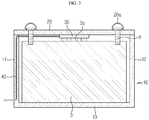
- FIG. 3 is a cross-sectioned view schematically showing the auxiliary battery storage device according to an embodiment of the present disclosure
- FIG. 4 is an enlarged view showing a power cable and an inlet of a cable passage of FIG. 2 .
- the auxiliary battery storage device 5 includes a case body 10, a case body cover 20, a terminal connection member 30, and a power cable 40.
- the auxiliary battery storage device 5 may be disposed at, for example, a bonnet or a rear trunk.
- the case body 10 may include a lower plate 13 and four side plates 11, 12 forming walls, and may be formed in a box shape with an open top portion.
- the auxiliary battery 3 may be placed in the inner space formed inside the case body 10. At this time, a power terminal 3a of the auxiliary battery is provided to face the open top portion of the case body 10.
- the lower plate 13 of the case body 10 may be fixed horizontally to a bottom surface of the bonnet or the trunk by a component such as a bracket.
- the side plates 11, 12 of the case body 10 define the inner space of the case body 10.
- the side plates 11, 12 may be formed at least higher than the height of the auxiliary battery 3 so that the auxiliary battery 3 is fully inserted into the inner space of the case body 10.
- the auxiliary battery 3 accommodated in the case body 10 may be protected from external impact by the side plates 11, 12.
- the side plates 11, 12 may be used as a wiring path of the power cable 40, explained later.
- the case body 10 is designed to have a rectangular parallelepiped box shape, but the shape of the case body 10 may be changed depending on the volume or the installation place of the auxiliary battery 3.
- the case body cover 20 is a component that closes the open top portion of the case body 10.
- the case body cover 20 according to this embodiment has a plate shape sized corresponding to the area of the open top portion of the case body 10 and is provided to be hinged to the case body 10.
- the case body cover 20 is rotatably coupled to any one side plate 11 of the side plates 11, 12 of the case body 10 by a hinge to open and close the top portion of the case body 10. That is, the top portion of the case body 10 may be opened or closed by rotating the case body cover 20.
- a terminal connection member 30 serving as is a component electrically connected to the power terminal 3a of the auxiliary battery is fixedly coupled to an inner surface of the case body cover 20.
- the terminal connection member 30 may be configured as a male connector having protruding pins 31, and the power terminal 3a of the auxiliary battery may be configured as a female connector having a socket that may be coupled with the protruding pins 31 in a receptacle manner.
- the terminal connection member 30 may be disposed at a center of the inner surface of the case body cover 20 so that the terminal connection member 30 is connected to the power terminal 3a of the auxiliary battery when the top portion of the case body 10 is completely closed by the case body cover 20.
- the protruding pins 31 of the terminal connection member 30 are connected to the power terminal 3a of the auxiliary battery, and if the case body cover 20 is opened, the protruding pins 31 of the terminal connection member 30 are disconnected from the power terminal 3a of the auxiliary battery.
- the position of the terminal connection member 30 may be changed corresponding to the position of the power terminal 3a of the auxiliary device.
- the terminal connection member 30 may be located at any position on the inner surface of the case body cover 20 as long as the terminal connection member 30 contacts the power terminal 3a of the auxiliary battery when the top portion of the case body 10 is closed by the case body cover 20.
- the main and the female connectors may be connected in any way such as a point contact method other than the receptacle method, as long as the main and the female connectors can be contacted with each other.
- the auxiliary battery storage device may further include a fastening member 20a that fixes the case body cover 20 and the auxiliary battery 3 in a state where the top portion of the case body 10 is closed by the case body cover 20.
- a bolt may be employed having a gripping ring formed in a head portion thereof.
- a bolt may be inserted into bolt fastening holes H, which are provided in corner regions of the case body cover 20 and the auxiliary battery 3 in one-to-one relationship, to integrally fix the case body cover 20 and the auxiliary battery 3.
- a worker may grip the gripping ring and turn the bolt, so that the bolt may be tightened without using a tool such as a spanner.
- the power cable 40 is a component for electrically connecting the auxiliary battery 3 and the main battery 2 and allows the auxiliary battery 3 to be separated from the main battery 2 and placed in a trunk space that is easily accessible to the driver.
- the power cable 40 is connected to the main battery 2 having one side connected to the terminal connection member 30 and the other side installed to the body frame. Thus, if the top portion of the case body 10 is closed by the case body cover 20, the power of the auxiliary battery 3 may be supplied to the main battery 2.
- the power cable 40 may extend from the terminal connection member 30 through the side plate 11 of the case body 10 to the outside of the case body 10 toward the main battery 2.
- the side plate 11 of the case body has a hollow structure in which a cable passage is provided.
- Two openings forming an entrance and an exit of the cable passage are respectively located at a top end and an outer side of the side plate 11 to which the case body cover 20 are hinged, and the cable passage may be formed to extend straightly downward from an inlet 14 located at the top end of the side plate 11 approximately to an outlet adjacent to a bottom end of the side plate 11.
- the top portion of the side plate 11 where the inlet 14 of the cable passage is located may be depressed compared to regions other than the top portion.
- the top portion of the side plate 11 corresponding to the inlet 14 of the cable passage may be concavely recessed relative to other portions.
- the cable passage is provided in the side plate 11 of the case body 10 as described above, the interference between the power cable 40 and the auxiliary battery 3 in the case body 10 may be minimized. Also, when the top portion of the case body 10 is closed by the case body cover 20, the power cable 40 may not interfere with the case body cover 20 at all.
- the auxiliary battery storage device 5 If the auxiliary battery storage device 5 according to the present disclosure having the above structure and operation is used, it is possible to protect the auxiliary battery 3 from external impact. Moreover, since the power terminal 3a of the auxiliary battery is connected to or disconnected from the power cable 40 by putting the auxiliary battery 3 into the case body 10 and opening or closing the case body 10 by the case body cover 20, it is not necessary to carry out the wiring work in a state of wearing safety equipment, different from the conventional art. Thus, the auxiliary battery 3 may be safely and easily exchanged even by an unskilled person.
- auxiliary battery storage device 5 according to another embodiment of the present disclosure will be described.
- the same reference numerals as those in the former embodiment denote the same components and will not be described in detail again, and features different from the former embodiment will be described in detail.
- FIGS. 5 and 6 are cross-sectioned views showing an auxiliary battery storage device 5 according to another embodiment of the present disclosure to illustrate the process of mounting or separating the case body cover 20 and loading or unloading the auxiliary battery 3
- FIGS. 7 and 8 are diagrams for illustrating the states before and after a hooking protrusion 21 of the case body cover 20 is operated according to another embodiment of the present disclosure.
- the auxiliary battery storage device 5 is configured to allow the worker to exchange the auxiliary battery 3 more conveniently than the former embodiment.
- the worker when fixing the case body cover 20 and the auxiliary battery 3, the worker must directly fasten the bolt, and if there is no tool such as a spanner, the fastening force for the bolt may not be sufficient.
- the case body cover 20 and the auxiliary battery 3 may be fixed and separated by turning on/off an opening/closing button, thereby eliminating the inconvenience of the former embodiment.
- hooking grooves 16 are provided at the two side plates 11, 12 of the case body 10, and hooking protrusions 21 engaging with the hooking grooves 16 are provided on the case body cover 20.
- the case body cover 20 may close or open the case body 10 as the hooking protrusions 21 and the hooking grooves 16 are engaged or disengaged.
- the hooking protrusion 21 may be configured to be horizontally movable by an electromagnetic force so as to be inserted into or released from the hooking groove 16.
- the case body cover 20 of this embodiment includes an electromagnet 22 and a pair of springs 23 therein.
- the hooking protrusion 21 may be mounted vertically to the case body cover 20 in a state where the top end of the hooking protrusion 21 is connected to the pair of springs 23.
- the pair of springs 23 may be spaced apart from each other by a predetermined distance in the width direction of the hooking protrusion, and the electromagnet may be disposed in the middle between the springs 23 while keeping a constant gap from the hooking protrusion 21.
- Four assemblies in which the electromagnet 22, the pair of springs 23 and the hooking protrusion 21 are combined may be assembled at four corners of the case body cover 20, respectively.
- the operating mechanism of the hooking protrusion 21 will be briefly described.
- the electromagnet 22 is a metal rod around which a coil is wound. If an electric current flows through the coil, an electromagnetic force is generated. Thus, as shown in FIG. 7 , if a switch is turned on so that a current flows through the electromagnet 22, the hooking protrusion 21 is pulled toward the electromagnet 22 and released from the hooking groove 16.
- at least the top end of the hooking protrusion 21 is made of metal.
- the hooking protrusion 21 may be elastically biased toward the hooking groove 16 by the elastic force of the spring 23 to engage with the hooking groove 16.
- the operation button may be disposed at an outer surface of the case cover 20, or the operation button may also be configured to turn the switch on/off wirelessly.
- the hooking protrusion 21 may further include a top end mounted to the case body cover 20 in a state of being connected to the spring 23, and a jaw 21a and a stopper 21b disposed below the top end.
- the jaw 21a is a portion that is substantially engaged with the hooking groove 16 in the hooking protrusion 21. That is, depending on the location of the jaw 21a with respect to the hooking groove 16 by the electromagnet 22 and the spring 23, it is determined whether the case body cover 20 and the case body 10 are coupled or separated.
- the stopper 21b is a portion that extends horizontally opposite to the jaw 21a.
- the stopper 21b may extend at least to a position at which the stopper may contact the upper surface of the auxiliary battery 3. As shown in FIG. 5 , when the top portion of the case body 10 is closed by the case body cover 20, the stopper 21b supports the upper surface of the auxiliary battery 3 downward.
- the gap between the case body cover 20 and the auxiliary battery 3 may be kept constant.
- the auxiliary battery storage device 5 may further include a lifting unit 50 for supporting a lower portion of the auxiliary battery 3 and moving the auxiliary battery 3 up and down to a preset height in the inner space of the case body 10.
- the lifting unit 50 relieves the effort of the worker when inserting or removing the auxiliary battery 3 into/from the case body 10.
- the lifting unit 50 is very useful.
- the lifting unit 50 may include a support plate 51 having a table shape and disposed to contact the lower surface of the auxiliary battery 3, a lifting rod 52 vertically connected to the support plate 51, and a driving motor 53 for moving the lifting rod 52 up and down.
- the support plate 51 is formed in a plate shape sized corresponding to the lower surface of the auxiliary battery 3a and is provided to have a substantially table shape to stably support the auxiliary battery 3.
- a rubber pad may be further provided on the upper surface of the support plate 51 to secure adhesion with the auxiliary battery 3.
- One side of the lifting rod 52 is connected to a lower portion of the support plate 51, and the other side thereof is connected to the driving motor 53 through the lower plate 13 of the case body 10.
- At least two lifting rods 52 may be provided to be vertically moved by the driving motor 53.
- the lifting rod 52 may be moved up and down in a rack and pinion manner.
- the driving motor 53 is a component for moving the lifting rod 52 up and down. Although not shown in detail, for example, if the driving motor 53 rotates a pinion, the pinion may move a rack corresponding to the lifting rod 52 up and down.
- a hydro-pneumatic actuator that generates an impellent force in the vertical direction may be used.
- the driving motor 53 may be embedded under the support surface where the case body 10 may be placed.
- a switch for operating the driving motor 53 may be placed on the side surface of the case body cover 20 or the case body 10 along with the switch for manipulating the hooking protrusion 21.
- the auxiliary battery storage device 5 according to another embodiment of the present disclosure is used, it will be very easy to attach or detach the case body cover 20 to/from the case body 10, fix the case body cover 20 and the auxiliary battery 3 to each other, and load or unload the auxiliary battery 3.
- the auxiliary battery storage device 5 may be applied to a vehicle such as an electric vehicle and a hybrid electric vehicle, which uses the auxiliary battery 3 or a similar fuel cell.
Landscapes
- Engineering & Computer Science (AREA)
- Power Engineering (AREA)
- Transportation (AREA)
- Mechanical Engineering (AREA)
- Chemical & Material Sciences (AREA)
- Chemical Kinetics & Catalysis (AREA)
- Electrochemistry (AREA)
- General Chemical & Material Sciences (AREA)
- Sustainable Energy (AREA)
- Life Sciences & Earth Sciences (AREA)
- Sustainable Development (AREA)
- Manufacturing & Machinery (AREA)
- Combustion & Propulsion (AREA)
- Microelectronics & Electronic Packaging (AREA)
- Battery Mounting, Suspending (AREA)
- Arrangement Or Mounting Of Propulsion Units For Vehicles (AREA)
- Electric Propulsion And Braking For Vehicles (AREA)
Abstract
Description
- The present disclosure relates to an auxiliary battery storage device, and more particularly, to a storage device capable of exchanging an auxiliary battery safety and conveniently.
- The present application claims priority to Korean Patent Application No.
10-2018-0028609 filed on March 12, 2018 - Generally, a battery module mounted on a high-output product such as an electric vehicle includes a plurality of cells connected in series or in parallel, since a high voltage is to be supplied to a load.
- If the battery module including the plurality of cells is discharged, the state of charges (SOCs) of the cells become different from each other due to the difference in the self-discharge rate of the cells.
- If the battery module is continuously discharged in a state where the SOC is unbalanced, certain cells having low SOC are overdischarged, which makes it difficult to stably operate the battery module.
- Conventionally, in order to solve the SOC imbalance between the cells, a buck method for eliminating the SOC imbalance between the cells by discharging cells having relatively high SOC and a boost method for eliminating the SOC imbalance between the cells by charging cells having relatively low SOC have been widely used.
- The buck method has a problem that energy is wasted during the cell balancing process, and the boost method has a disadvantage that the circuit design becomes complicated because a charge circuit must be connected to every cell.
- Among known cell balancing methods, there is a method of using an auxiliary battery as disclosed in Korean Unexamined Patent No.
10-2014-0028350 - In the method of utilizing the auxiliary battery, the auxiliary battery is connected to cells having relatively high SOC, and the electric energy stored in the cells are discharged to charge the auxiliary battery. If so, the buck-type cell balancing is achieved, and energy is not wasted in this process.
- Also, if the auxiliary battery is charged to some extent, the auxiliary battery is connected to cells having relatively low SOC to discharge the electric energy stored in the auxiliary battery so that the cells having relatively low SOC are charged. Then, unlike the existing boost method, it is possible to realize cell balancing by recycling the energy stored in the auxiliary battery even though there is no separate current source for generating the charging current.
- However, the cell balancing method using the auxiliary battery has a problem that the auxiliary battery is rapidly degraded because the auxiliary battery is frequently charged and discharged. If the battery is degraded, internal resistance is increased to generate heat, and negative reaction occurs inside the battery to generate gas. Thus, if the auxiliary battery is degraded, safety of the cell balancing is deteriorated.
- To solve this problem, the auxiliary battery should be exchanged periodically. However, in the conventional technology, since the auxiliary battery is installed in the exterior of the battery along with a plurality of cells, it is troublesome to disassemble the exterior of the battery in order to exchange the auxiliary battery. In particular, in the case of an electric vehicle, since the battery is mounted below a body frame, lifting equipment and maintenance experts are needed to lift the electric vehicle and exchange the auxiliary battery.
- As a solution thereto, as disclosed in Korean Unexamined Patent Publication No.
10-2016-0046221 - However, even though the auxiliary battery is installed in a space directly accessible to a driver, such as a car bonnet or a rear trunk, it is still not easy for an unskilled person to exchange the auxiliary battery due to space constraints, resultant complicated wiring and safety reasons.
- The present disclosure is designed to solve the problems of the related art, and therefore the present disclosure is directed to providing an auxiliary battery storage device, which allows an auxiliary battery to be electrically connected to a main battery while the auxiliary battery is being stored so that the auxiliary battery may be easily exchanged even by an unskilled person.
- These and other objects and advantages of the present disclosure may be understood from the following detailed description and will become more fully apparent from the exemplary embodiments of the present disclosure. Also, it will be easily understood that the objects and advantages of the present disclosure may be realized by the means shown in the appended claims and combinations thereof.
- In one aspect of the present disclosure, there is provided an auxiliary battery storage device for storing an auxiliary battery that is used for performing cell balancing to a main battery adopted in an electric vehicle or supplying power to the main battery having low state of charge (SOC), the auxiliary battery storage device comprising: a case body formed in a box shape with an open top portion to have an inner space in which the auxiliary battery is stored; a case body cover coupled to the case body to open or close the open top portion of the case body; a terminal connection member fixed to an inner surface of the case body cover to contact a power terminal of the auxiliary battery when the top portion of the case body is closed by the case body cover; and a power cable configured to extend from the terminal connection member to the main battery.
- The terminal connection member may include a protruding pin provided to be connected to or disconnected from the power terminal of the auxiliary battery in a receptacle manner.
- The auxiliary battery storage device may further comprise a fastening member configured to fix the case body cover to the auxiliary battery, wherein the fastening member may be at least one bolt that has a gripping ring at a head portion thereof and is integrally connected to the case body cover and the auxiliary battery.
- The case body may include a cable passage formed in at least one side plate thereof so that the power cable passes therethrough.
- The case body cover may be hinged to one side plate of the case body, the cable passage may have two openings forming an entrance and an exit thereof so that the two openings are located at a top end and an outer side of the side plate, and the top end of the side plate at which the opening is located may be depressed down compared to other regions.
- The case body may have hooking grooves formed in side plates thereof facing each other, and the case body cover may have hooking protrusions engaged with the hooking grooves so that the case body and the case body cover are coupled to each other, and the hooking protrusions may be respectively moved by an electromagnetic force to be engaged with or disengaged from the hooking grooves.
- The case body cover may include an electromagnet disposed at a position spaced apart from the hooking protrusion by a predetermined distance to pull the hooking protrusion by an electromagnetic force to be disengaged from the hooking groove; and a spring configured to elastically bias the hooking protrusion toward the hooking groove so that the hooking protrusion is engaged with the hooking groove.
- The hooking protrusion may include a jaw engaged with the hooking groove; and a stopper configured to extend opposite to the jaw to support an upper surface of the auxiliary battery downward.
- The auxiliary battery storage device may further comprise a lifting unit configured to move the auxiliary battery up and down to a preset height in the case body.
- The lifting unit may include a support plate formed with a table shape to support the auxiliary battery inside the case body; a lifting rod configured to vertically pass through a lower plate of the case body and be connected to the support plate; and a driving motor configured to move the lifting rod up and down.
- In another aspect of the present disclosure, there is also provided an electric vehicle, comprising the auxiliary battery storage device described above.
- According to one embodiment of the present disclosure, since the auxiliary battery and the main battery may be electrically connected only by inserting the auxiliary battery into the case body and covering the case body by the case body cover, the auxiliary battery may be safely and easily exchanged even by an unskilled person.
- According to another embodiment of the present disclosure, since the case body cover and the auxiliary battery are coupled to keep the gap therebetween constant, the electrical connection between the connector on the case body cover and the power terminal of the auxiliary battery may be stably maintained even when external shocks or vibrations are applied thereto.
- According to still another embodiment of the present disclosure, it may become very easy to mount or separate the case body cover and to load or unload the auxiliary battery.
- The accompanying drawings illustrate a preferred embodiment of the present disclosure and together with the foregoing disclosure, serve to provide further understanding of the technical features of the present disclosure, and thus, the present disclosure is not construed as being limited to the drawing.
-
FIG. 1 is a diagram for schematically illustrating loading locations of an auxiliary battery and an auxiliary battery storage device according to an embodiment of the present disclosure. -
FIG. 2 is a perspective view schematically showing the auxiliary battery storage device according to an embodiment of the present disclosure. -
FIG. 3 is a cross-sectioned view schematically showing the auxiliary battery storage device according to an embodiment of the present disclosure. -
FIG. 4 is an enlarged view showing a power cable and an inlet of a cable passage ofFIG. 2 . -
FIGS. 5 and6 are cross-sectioned views showing an auxiliary battery storage device according to another embodiment of the present disclosure to illustrate the process of mounting or separating the case body cover and loading or unloading the auxiliary battery. -
FIGS. 7 and 8 are diagrams for illustrating the states before and after a hooking protrusion of the case body cover is operated according to another embodiment of the present disclosure. - Hereinafter, preferred embodiments of the present disclosure will be described in detail with reference to the accompanying drawings. Prior to the description, it should be understood that the terms used in the specification and the appended claims should not be construed as limited to general and dictionary meanings, but interpreted based on the meanings and concepts corresponding to technical aspects of the present disclosure on the basis of the principle that the inventor is allowed to define terms appropriately for the best explanation.
- Therefore, the description proposed herein is just a preferable example for the purpose of illustrations only, not intended to limit the scope of the disclosure, so it should be understood that other equivalents and modifications could be made thereto without departing from the scope of the disclosure.
- An
auxiliary battery 3 mentioned in this specification may mean a battery used for performing cell balancing to amain battery 2 adopted in an electric vehicle 1 or supplying power to themain battery 2 with a low state of charge (SOC). For example, in themain battery 2, theauxiliary battery 3 discharges the electric energy stored in cells having relatively high SOC to equalize the SOC with the other cells, and the discharged electric energy is used to charge theauxiliary battery 3. In addition, theauxiliary battery 3 is connected to cells having relatively low SOC to discharge the electric energy stored in theauxiliary battery 3 so that the cells having relatively low SOC are charged to equalize the SOC with the other cells. - The
auxiliary battery 3 may be installed at a location at which theauxiliary battery 3 may be easily maintained and easily exchanged at emergency separately from themain battery 2. An auxiliary battery storage device 5 may be understood as an article used to accommodate and store theauxiliary battery 3. The auxiliary battery storage device 5 according to the present disclosure may also be used to accommodate a fuel cell (serving for starting a general vehicle or supplying power to various devices) having a similar function and structure to theauxiliary battery 3. - As shown in
FIG. 1 , themain battery 2 may be coupled to a lower frame of the vehicle, and theauxiliary battery 3 may be mounted to a bonnet or a rear trunk of the vehicle. Themain battery 2 and theauxiliary battery 3 may be electrically connected through apower cable 40. - If the
auxiliary battery 3 breaks down or has a trouble, a driver may open the bonnet or the rear trunk to exchange theauxiliary battery 3. The auxiliary battery storage device 5 according to the present disclosure is a device for casing theauxiliary battery 3, and when theauxiliary battery 3 is exchanged, a newauxiliary battery 3 may be accommodated in the auxiliary battery storage device 5 and simultaneously connected to the auxiliary battery storage device 5. - As will be described later in detail, if the auxiliary battery storage device 5 according to the present disclosure is used, a new
auxiliary battery 3 is electrically connected to themain battery 2 only by mounting the newauxiliary battery 3 to the storage device. Thus, theauxiliary battery 3 may be exchanged safety and easily even by an unskilled person. Hereinafter, the auxiliary battery storage device 5 will be described in detail with reference toFIGS. 2 to 4 . -
FIG. 2 is a perspective view schematically showing the auxiliary battery storage device according to an embodiment of the present disclosure,FIG. 3 is a cross-sectioned view schematically showing the auxiliary battery storage device according to an embodiment of the present disclosure, andFIG. 4 is an enlarged view showing a power cable and an inlet of a cable passage ofFIG. 2 . - Referring to
FIGS. 2 to 4 , the auxiliary battery storage device 5 according to an embodiment of the present disclosure includes acase body 10, acase body cover 20, aterminal connection member 30, and apower cable 40. The auxiliary battery storage device 5 may be disposed at, for example, a bonnet or a rear trunk. - The
case body 10 may include alower plate 13 and fourside plates - The
auxiliary battery 3 may be placed in the inner space formed inside thecase body 10. At this time, apower terminal 3a of the auxiliary battery is provided to face the open top portion of thecase body 10. - Though not shown in the figures for convenience, the
lower plate 13 of thecase body 10 may be fixed horizontally to a bottom surface of the bonnet or the trunk by a component such as a bracket. - The
side plates case body 10 define the inner space of thecase body 10. In particular, theside plates auxiliary battery 3 so that theauxiliary battery 3 is fully inserted into the inner space of thecase body 10. Theauxiliary battery 3 accommodated in thecase body 10 may be protected from external impact by theside plates side plates power cable 40, explained later. - Meanwhile, in this embodiment, the
case body 10 is designed to have a rectangular parallelepiped box shape, but the shape of thecase body 10 may be changed depending on the volume or the installation place of theauxiliary battery 3. - The
case body cover 20 is a component that closes the open top portion of thecase body 10. The case body cover 20 according to this embodiment has a plate shape sized corresponding to the area of the open top portion of thecase body 10 and is provided to be hinged to thecase body 10. - For example, the
case body cover 20 is rotatably coupled to any oneside plate 11 of theside plates case body 10 by a hinge to open and close the top portion of thecase body 10. That is, the top portion of thecase body 10 may be opened or closed by rotating thecase body cover 20. - A
terminal connection member 30 serving as is a component electrically connected to thepower terminal 3a of the auxiliary battery is fixedly coupled to an inner surface of thecase body cover 20. - The
terminal connection member 30 according to this embodiment may be configured as a male connector having protrudingpins 31, and thepower terminal 3a of the auxiliary battery may be configured as a female connector having a socket that may be coupled with the protruding pins 31 in a receptacle manner. - As shown in
FIG. 3 , theterminal connection member 30 may be disposed at a center of the inner surface of the case body cover 20 so that theterminal connection member 30 is connected to thepower terminal 3a of the auxiliary battery when the top portion of thecase body 10 is completely closed by thecase body cover 20. - Thus, if the top portion of the
case body 10 is closed by thecase body cover 20, the protruding pins 31 of theterminal connection member 30 are connected to thepower terminal 3a of the auxiliary battery, and if thecase body cover 20 is opened, the protruding pins 31 of theterminal connection member 30 are disconnected from thepower terminal 3a of the auxiliary battery. - The position of the
terminal connection member 30 may be changed corresponding to the position of thepower terminal 3a of the auxiliary device. Namely, theterminal connection member 30 may be located at any position on the inner surface of the case body cover 20 as long as theterminal connection member 30 contacts thepower terminal 3a of the auxiliary battery when the top portion of thecase body 10 is closed by thecase body cover 20. In addition, the main and the female connectors may be connected in any way such as a point contact method other than the receptacle method, as long as the main and the female connectors can be contacted with each other. - Meanwhile, the auxiliary battery storage device according to the present disclosure may further include a
fastening member 20a that fixes thecase body cover 20 and theauxiliary battery 3 in a state where the top portion of thecase body 10 is closed by thecase body cover 20. - As the
fastening member 20a, a bolt may be employed having a gripping ring formed in a head portion thereof. As shown inFIG. 2 , a bolt may be inserted into bolt fastening holes H, which are provided in corner regions of thecase body cover 20 and theauxiliary battery 3 in one-to-one relationship, to integrally fix thecase body cover 20 and theauxiliary battery 3. At this time, a worker may grip the gripping ring and turn the bolt, so that the bolt may be tightened without using a tool such as a spanner. - In this way, as the
case body cover 20 and theauxiliary battery 3 are fastened by the bolt, a gap may not be generated between thecase body cover 20 and theauxiliary battery 3 even when shock or vibration is applied thereto while the vehicle is running. Thus, the contact state between the main and thefemale connectors 30, 5a may be stably maintained. - The
power cable 40 is a component for electrically connecting theauxiliary battery 3 and themain battery 2 and allows theauxiliary battery 3 to be separated from themain battery 2 and placed in a trunk space that is easily accessible to the driver. - The
power cable 40 is connected to themain battery 2 having one side connected to theterminal connection member 30 and the other side installed to the body frame. Thus, if the top portion of thecase body 10 is closed by thecase body cover 20, the power of theauxiliary battery 3 may be supplied to themain battery 2. - As shown in
FIGS. 2 and3 , thepower cable 40 according to this embodiment may extend from theterminal connection member 30 through theside plate 11 of thecase body 10 to the outside of thecase body 10 toward themain battery 2. To this end, theside plate 11 of the case body has a hollow structure in which a cable passage is provided. - Two openings forming an entrance and an exit of the cable passage are respectively located at a top end and an outer side of the
side plate 11 to which the case body cover 20 are hinged, and the cable passage may be formed to extend straightly downward from aninlet 14 located at the top end of theside plate 11 approximately to an outlet adjacent to a bottom end of theside plate 11. - The top portion of the
side plate 11 where theinlet 14 of the cable passage is located may be depressed compared to regions other than the top portion. In other words, as shown inFIG. 4 , the top portion of theside plate 11 corresponding to theinlet 14 of the cable passage may be concavely recessed relative to other portions. - Since the cable passage is provided in the
side plate 11 of thecase body 10 as described above, the interference between thepower cable 40 and theauxiliary battery 3 in thecase body 10 may be minimized. Also, when the top portion of thecase body 10 is closed by thecase body cover 20, thepower cable 40 may not interfere with the case body cover 20 at all. - If the auxiliary battery storage device 5 according to the present disclosure having the above structure and operation is used, it is possible to protect the
auxiliary battery 3 from external impact. Moreover, since thepower terminal 3a of the auxiliary battery is connected to or disconnected from thepower cable 40 by putting theauxiliary battery 3 into thecase body 10 and opening or closing thecase body 10 by thecase body cover 20, it is not necessary to carry out the wiring work in a state of wearing safety equipment, different from the conventional art. Thus, theauxiliary battery 3 may be safely and easily exchanged even by an unskilled person. - Subsequently, an auxiliary battery storage device 5 according to another embodiment of the present disclosure will be described. The same reference numerals as those in the former embodiment denote the same components and will not be described in detail again, and features different from the former embodiment will be described in detail.
-
FIGS. 5 and6 are cross-sectioned views showing an auxiliary battery storage device 5 according to another embodiment of the present disclosure to illustrate the process of mounting or separating thecase body cover 20 and loading or unloading theauxiliary battery 3, andFIGS. 7 and 8 are diagrams for illustrating the states before and after a hookingprotrusion 21 of thecase body cover 20 is operated according to another embodiment of the present disclosure. - The auxiliary battery storage device 5 according to another embodiment of the present disclosure is configured to allow the worker to exchange the
auxiliary battery 3 more conveniently than the former embodiment. In the former embodiment, when fixing thecase body cover 20 and theauxiliary battery 3, the worker must directly fasten the bolt, and if there is no tool such as a spanner, the fastening force for the bolt may not be sufficient. Meanwhile, in this embodiment, thecase body cover 20 and theauxiliary battery 3 may be fixed and separated by turning on/off an opening/closing button, thereby eliminating the inconvenience of the former embodiment. - As shown in
FIGS. 5 and6 , hookinggrooves 16 are provided at the twoside plates case body 10, and hookingprotrusions 21 engaging with the hookinggrooves 16 are provided on thecase body cover 20. The case body cover 20 may close or open thecase body 10 as the hookingprotrusions 21 and the hookinggrooves 16 are engaged or disengaged. At this time, the hookingprotrusion 21 may be configured to be horizontally movable by an electromagnetic force so as to be inserted into or released from the hookinggroove 16. - As shown in
FIGS. 7 and 8 , the case body cover 20 of this embodiment includes anelectromagnet 22 and a pair ofsprings 23 therein. The hookingprotrusion 21 may be mounted vertically to the case body cover 20 in a state where the top end of the hookingprotrusion 21 is connected to the pair ofsprings 23. - The pair of
springs 23 may be spaced apart from each other by a predetermined distance in the width direction of the hooking protrusion, and the electromagnet may be disposed in the middle between thesprings 23 while keeping a constant gap from the hookingprotrusion 21. Four assemblies in which theelectromagnet 22, the pair ofsprings 23 and the hookingprotrusion 21 are combined may be assembled at four corners of thecase body cover 20, respectively. - The operating mechanism of the hooking
protrusion 21 will be briefly described. Theelectromagnet 22 is a metal rod around which a coil is wound. If an electric current flows through the coil, an electromagnetic force is generated. Thus, as shown inFIG. 7 , if a switch is turned on so that a current flows through theelectromagnet 22, the hookingprotrusion 21 is pulled toward theelectromagnet 22 and released from the hookinggroove 16. Here, at least the top end of the hookingprotrusion 21 is made of metal. - Conversely, as shown in
FIG. 8 , if the switch is turned off to cut off the current to theelectromagnet 22, the hookingprotrusion 21 may be elastically biased toward the hookinggroove 16 by the elastic force of thespring 23 to engage with the hookinggroove 16. - Even though an operation button for turning on/off the switch is conceptually depicted in the figures, the operation button may be disposed at an outer surface of the
case cover 20, or the operation button may also be configured to turn the switch on/off wirelessly. - In particular, as shown in the enlarged view of
FIG. 5 , the hookingprotrusion 21 may further include a top end mounted to the case body cover 20 in a state of being connected to thespring 23, and ajaw 21a and astopper 21b disposed below the top end. - The
jaw 21a is a portion that is substantially engaged with the hookinggroove 16 in the hookingprotrusion 21. That is, depending on the location of thejaw 21a with respect to the hookinggroove 16 by theelectromagnet 22 and thespring 23, it is determined whether thecase body cover 20 and thecase body 10 are coupled or separated. - The
stopper 21b is a portion that extends horizontally opposite to thejaw 21a. Thestopper 21b may extend at least to a position at which the stopper may contact the upper surface of theauxiliary battery 3. As shown inFIG. 5 , when the top portion of thecase body 10 is closed by thecase body cover 20, thestopper 21b supports the upper surface of theauxiliary battery 3 downward. - Since the
case body cover 20 is engaged with thecase body 10 and theauxiliary battery 3 is supported downward by thestopper 21b of thecase body cover 20, the gap between thecase body cover 20 and theauxiliary battery 3 may be kept constant. Thus, it is possible to prevent a clearance from being formed between the male connector of thecase body cover 20 and the female connector of thepower terminal 3a of the auxiliary battery. - Meanwhile, the auxiliary battery storage device 5 according to another embodiment of the present disclosure may further include a
lifting unit 50 for supporting a lower portion of theauxiliary battery 3 and moving theauxiliary battery 3 up and down to a preset height in the inner space of thecase body 10. The liftingunit 50 relieves the effort of the worker when inserting or removing theauxiliary battery 3 into/from thecase body 10. In particular, if the inner space of thecase body 10 has a great depth and theauxiliary battery 3 is heavy due to a very large capacity, the liftingunit 50 is very useful. - Referring to
FIGS. 5 and6 , the liftingunit 50 may include asupport plate 51 having a table shape and disposed to contact the lower surface of theauxiliary battery 3, a liftingrod 52 vertically connected to thesupport plate 51, and a drivingmotor 53 for moving the liftingrod 52 up and down. - The
support plate 51 is formed in a plate shape sized corresponding to the lower surface of theauxiliary battery 3a and is provided to have a substantially table shape to stably support theauxiliary battery 3. A rubber pad may be further provided on the upper surface of thesupport plate 51 to secure adhesion with theauxiliary battery 3. - One side of the lifting
rod 52 is connected to a lower portion of thesupport plate 51, and the other side thereof is connected to the drivingmotor 53 through thelower plate 13 of thecase body 10. At least two liftingrods 52 may be provided to be vertically moved by the drivingmotor 53. For example, the liftingrod 52 may be moved up and down in a rack and pinion manner. - The driving
motor 53 is a component for moving the liftingrod 52 up and down. Although not shown in detail, for example, if the drivingmotor 53 rotates a pinion, the pinion may move a rack corresponding to the liftingrod 52 up and down. As an alternative of the liftingunit 50 by the drivingmotor 53, a hydro-pneumatic actuator that generates an impellent force in the vertical direction may be used. - The driving
motor 53 may be embedded under the support surface where thecase body 10 may be placed. For example, a switch for operating the drivingmotor 53 may be placed on the side surface of the case body cover 20 or thecase body 10 along with the switch for manipulating the hookingprotrusion 21. - The auxiliary battery storage device 5 according to another embodiment of the present disclosure is used, it will be very easy to attach or detach the case body cover 20 to/from the
case body 10, fix thecase body cover 20 and theauxiliary battery 3 to each other, and load or unload theauxiliary battery 3. - The auxiliary battery storage device 5 may be applied to a vehicle such as an electric vehicle and a hybrid electric vehicle, which uses the
auxiliary battery 3 or a similar fuel cell. - The present disclosure has been described in detail. However, it should be understood that the detailed description and specific examples, while indicating preferred embodiments of the disclosure, are given by way of illustration only, since various changes and modifications within the scope of the disclosure will become apparent to those skilled in the art from this detailed description.
- Meanwhile, even though the terms expressing directions such as "upper", "lower", "left" and "right" are used in the specification, they are just for convenience of description and can be expressed differently depending on the location of a viewer or a subject, as apparent to those skilled in the art.
Claims (11)
- An auxiliary battery storage device for storing an auxiliary battery that is used for performing cell balancing to a main battery adopted in an electric vehicle or supplying power to the main battery having low state of charge (SOC), the auxiliary battery storage device comprising:a case body formed in a box shape with an open top portion to have an inner space in which the auxiliary battery is stored;a case body cover coupled to the case body to open or close the open top portion of the case body;a terminal connection member fixed to an inner surface of the case body cover to contact a power terminal of the auxiliary battery when the top portion of the case body is closed by the case body cover; anda power cable configured to extend from the terminal connection member to the main battery.
- The auxiliary battery storage device according to claim 1,
wherein the terminal connection member includes a protruding pin provided to be connected to or disconnected from the power terminal of the auxiliary battery in a receptacle manner. - The auxiliary battery storage device according to claim 1, further comprising:a fastening member configured to fix the case body cover to the auxiliary battery,wherein the fastening member is at least one bolt that has a gripping ring at a head portion thereof and is integrally connected to the case body cover and the auxiliary battery.
- The auxiliary battery storage device according to claim 1,
wherein the case body includes a cable passage formed in at least one side plate thereof so that the power cable passes therethrough. - The auxiliary battery storage device according to claim 4,
wherein the case body cover is hinged to one side plate of the case body,
wherein the cable passage has two openings forming an entrance and an exit thereof so that the two openings are located at a top end and an outer side of the side plate, and
wherein the top end of the side plate at which the opening is located is depressed down compared to other regions. - The auxiliary battery storage device according to claim 4,
wherein the case body has hooking grooves formed in side plates thereof facing each other, and the case body cover has hooking protrusions engaged with the hooking grooves so that the case body and the case body cover are coupled to each other, and
wherein the hooking protrusions are respectively moved by an electromagnetic force to be engaged with or disengaged from the hooking grooves. - The auxiliary battery storage device according to claim 6,
wherein the case body cover includes:an electromagnet disposed at a position spaced apart from the hooking protrusion by a predetermined distance to pull the hooking protrusion by an electromagnetic force to be disengaged from the hooking groove; anda spring configured to elastically bias the hooking protrusion toward the hooking groove so that the hooking protrusion is engaged with the hooking groove. - The auxiliary battery storage device according to claim 6,
wherein the hooking protrusion includes:a jaw engaged with the hooking groove; anda stopper configured to extend opposite to the jaw to support an upper surface of the auxiliary battery downward. - The auxiliary battery storage device according to claim 1, further comprising:
a lifting unit configured to move the auxiliary battery up and down to a preset height in the case body. - The auxiliary battery storage device according to claim 9,
wherein the lifting unit includes:a support plate formed with a table shape to support the auxiliary battery inside the case body;a lifting rod configured to vertically pass through a lower plate of the case body and be connected to the support plate; anda driving motor configured to move the lifting rod up and down. - An electric vehicle, comprising the auxiliary battery storage device according to any one of claims 1 to 10.
Applications Claiming Priority (2)
| Application Number | Priority Date | Filing Date | Title |
|---|---|---|---|
| KR1020180028609A KR102275879B1 (en) | 2018-03-12 | 2018-03-12 | Auxiliary Battery storage device for Electric vehicle |
| PCT/KR2019/001997 WO2019177274A1 (en) | 2018-03-12 | 2019-02-19 | Auxiliary battery accommodating device for electric vehicle |
Publications (3)
| Publication Number | Publication Date |
|---|---|
| EP3674131A1 true EP3674131A1 (en) | 2020-07-01 |
| EP3674131A4 EP3674131A4 (en) | 2020-11-18 |
| EP3674131B1 EP3674131B1 (en) | 2025-02-19 |
Family
ID=67908458
Family Applications (1)
| Application Number | Title | Priority Date | Filing Date |
|---|---|---|---|
| EP19766988.0A Active EP3674131B1 (en) | 2018-03-12 | 2019-02-19 | Auxiliary battery accommodating device for electric vehicle |
Country Status (8)
| Country | Link |
|---|---|
| US (1) | US11390174B2 (en) |
| EP (1) | EP3674131B1 (en) |
| JP (1) | JP7045581B2 (en) |
| KR (1) | KR102275879B1 (en) |
| CN (1) | CN211543275U (en) |
| ES (1) | ES3015985T3 (en) |
| HU (1) | HUE070912T2 (en) |
| WO (1) | WO2019177274A1 (en) |
Families Citing this family (14)
| Publication number | Priority date | Publication date | Assignee | Title |
|---|---|---|---|---|
| CN110962564B (en) * | 2019-12-04 | 2020-11-24 | 江苏飞船股份有限公司 | Power battery mounting mechanism of electric automobile |
| US12519335B2 (en) | 2020-03-30 | 2026-01-06 | Panasonic Energy Co., Ltd. | Secondary battery system |
| CN112109535B (en) * | 2020-08-25 | 2022-02-01 | 东风汽车集团有限公司 | Battery locking mechanism |
| KR102468744B1 (en) * | 2020-12-17 | 2022-11-18 | 한국항공우주연구원 | Satellite projectile capable of charging cubesat |
| JP7574335B2 (en) * | 2021-02-09 | 2024-10-28 | 本田技研工業株式会社 | Vehicles for travel |
| JP7487152B2 (en) * | 2021-07-05 | 2024-05-20 | 株式会社豊田自動織機 | Fuel Cell Unit |
| CN113258203B (en) * | 2021-07-06 | 2021-09-28 | 深圳市小樱桃实业有限公司 | New energy automobile battery fixing device |
| CN114335871B (en) * | 2021-12-08 | 2023-05-09 | 中科检测技术服务(重庆)有限公司 | New energy automobile battery dismounting device |
| CN114435164B (en) * | 2022-03-24 | 2022-09-09 | 深圳市联兆电子有限公司 | Automatic charging system of storage battery for electric automobile |
| CN217306685U (en) * | 2022-06-02 | 2022-08-26 | 宁德时代新能源科技股份有限公司 | Isolator Panel Assemblies, Batteries and Consumers |
| CN115320514A (en) * | 2022-08-13 | 2022-11-11 | 长春捷翼汽车零部件有限公司 | Automobile and electric appliance control system and method thereof |
| KR102884734B1 (en) * | 2022-12-22 | 2025-11-12 | 주식회사 젠트로피 | battery pack exchange type electric motorcycle |
| GB2633567A (en) * | 2023-09-13 | 2025-03-19 | Mercedes Benz Group Ag | A portable battery for an electric vehicle comprising a traction battery |
| EP4531177A1 (en) * | 2023-09-27 | 2025-04-02 | Automotive Cells Company SE | Electric battery housing and method of assembling the same |
Family Cites Families (46)
| Publication number | Priority date | Publication date | Assignee | Title |
|---|---|---|---|---|
| JPS60131963U (en) | 1984-02-14 | 1985-09-03 | 三菱農機株式会社 | Battery support device |
| JPS6122914U (en) | 1984-07-14 | 1986-02-10 | 株式会社島津製作所 | fixing screw |
| JPH0416359Y2 (en) | 1985-05-02 | 1992-04-13 | ||
| JPH0737565A (en) | 1993-07-20 | 1995-02-07 | Toyota Autom Loom Works Ltd | Mounting structure for battery |
| JPH07315780A (en) | 1994-05-20 | 1995-12-05 | Toyota Autom Loom Works Ltd | Battery forklift |
| JPH07329858A (en) | 1994-06-11 | 1995-12-19 | Honda Motor Co Ltd | Battery attachment / detachment structure for electric assisted bicycles |
| KR970002224U (en) * | 1995-06-12 | 1997-01-24 | 전윤식 | Electric fan |
| JPH09274906A (en) | 1996-04-05 | 1997-10-21 | Toyota Motor Corp | In-vehicle battery structure |
| JPH11208388A (en) * | 1998-01-26 | 1999-08-03 | Clarion Co Ltd | Battery mounting structure |
| DE69916669T2 (en) | 1998-01-07 | 2005-04-28 | Clarion Co., Ltd. | Vehicle-mounted record carrier reproducing apparatus |
| JPH11341700A (en) | 1998-05-23 | 1999-12-10 | Honda Access Corp | On-vehicle power supply equipment |
| KR100356667B1 (en) | 1999-12-21 | 2002-10-19 | 기아자동차주식회사 | vehicle battery having an electric chargeable battery used as sub battery |
| JP2001229899A (en) | 2000-02-18 | 2001-08-24 | Tadayuki Sudo | Car battery utilization container |
| JP2004179120A (en) | 2002-11-29 | 2004-06-24 | Fuji Photo Film Co Ltd | Battery lid lock device |
| JP2004327223A (en) * | 2003-04-24 | 2004-11-18 | Matsushita Electric Ind Co Ltd | Battery storage device, power supply device, and electric vehicle |
| FR2871943A1 (en) | 2004-06-18 | 2005-12-23 | Renault Sas | DEVICE FOR POSITIONING AND FIXING A MOTOR VEHICLE HOUSING, IN PARTICULAR A BATTERY, AND ASSOCIATED METHOD |
| JP4613676B2 (en) * | 2005-04-12 | 2011-01-19 | 株式会社トヨトミ | Small household power supply |
| JP5220588B2 (en) | 2005-05-02 | 2013-06-26 | エルジー・ケム・リミテッド | Medium or large improved battery pack with improved safety |
| KR100903185B1 (en) | 2005-05-02 | 2009-06-17 | 주식회사 엘지화학 | Improved medium and large battery packs with improved safety |
| WO2008108091A1 (en) | 2007-03-08 | 2008-09-12 | Nikon Corporation | Battery receiving device, portable device, output device, and head mount display |
| JP5151214B2 (en) * | 2007-03-30 | 2013-02-27 | パナソニック株式会社 | Battery storage mechanism |
| JP5143824B2 (en) | 2007-04-02 | 2013-02-13 | 見敏 石井 | Battery storage device |
| US8146694B2 (en) * | 2009-01-20 | 2012-04-03 | Vahid Hamidi | Swappable modulated battery packs system for electrically driven vehicle |
| EP2637233B1 (en) * | 2010-11-04 | 2017-09-06 | Makita Corporation | Battery pack |
| JP6058260B2 (en) | 2011-10-28 | 2017-01-11 | 株式会社東芝 | Storage battery unit |
| KR101304220B1 (en) | 2011-12-23 | 2013-09-05 | 대동공업주식회사 | A battery cover and battery mounting device for electric vehicle |
| WO2013143460A1 (en) * | 2012-03-27 | 2013-10-03 | 台湾立凯绿能移动股份有限公司 | Fixing device group for removable battery of electric vehicle, and locking method thereof |
| KR101882007B1 (en) * | 2012-07-18 | 2018-07-25 | 에스케이이노베이션 주식회사 | Battery pack |
| KR20140028350A (en) | 2012-08-28 | 2014-03-10 | 에스케이이노베이션 주식회사 | Battery apparatus using auxiliary cell for cell balancing |
| KR101429747B1 (en) | 2012-12-20 | 2014-08-12 | 한국항공우주연구원 | Battery pack including assistant battery, moving object and control method thereof |
| JP2014147197A (en) | 2013-01-29 | 2014-08-14 | Hitachi Automotive Systems Ltd | Battery control device |
| JP6274504B2 (en) | 2013-11-29 | 2018-02-07 | 日産自動車株式会社 | Battery system |
| KR101795829B1 (en) | 2013-12-03 | 2017-11-08 | 주식회사 엘지화학 | Battery pack |
| NO340313B1 (en) * | 2014-01-08 | 2017-03-27 | Jakob Hatteland Logistics As | Remote controlled vehicle for picking up storage containers from a storage system, storage system for storage of containers and method for replacing a power source |
| JP6346758B2 (en) | 2014-02-28 | 2018-06-20 | ヤマハ発動機株式会社 | Electric assist bicycle and battery case |
| DE102014206646A1 (en) | 2014-04-07 | 2015-10-08 | Robert Bosch Gmbh | Energy storage unit, in particular battery module, and energy storage system with a plurality of energy storage units |
| KR101746139B1 (en) | 2014-10-20 | 2017-06-12 | 주식회사 엘지화학 | Apparatus for Cell Balancing Using Auxiliary Battery and Method thereof |
| US9827865B2 (en) | 2014-12-30 | 2017-11-28 | General Electric Company | Systems and methods for recharging vehicle-mounted energy storage devices |
| KR101674991B1 (en) | 2016-01-15 | 2016-11-11 | 경상북도(농업기술원) | Battery cover for farming machine having improved assembly structure |
| KR102010017B1 (en) | 2016-02-05 | 2019-08-12 | 주식회사 엘지화학 | Secondary battery module improved in preventing structure of battery overcharge |
| KR101647825B1 (en) | 2016-04-11 | 2016-08-11 | 김정연 | Battery Pack for Electric Vehicles |
| US20170366019A1 (en) | 2016-06-16 | 2017-12-21 | EcoReco Global Corporation | Battery Switching System and Method Thereof |
| CA3024416C (en) * | 2016-06-27 | 2024-05-28 | Volvo Group Canada Inc. | Interface sealing component for a battery cover assembly, and related systems and methods |
| KR101876629B1 (en) | 2016-09-09 | 2018-07-10 | 한국산업기술대학교산학협력단 | Apparatus and method for monitoring condition based on bicdata analysis |
| KR102162968B1 (en) * | 2017-04-07 | 2020-10-07 | 주식회사 엘지화학 | Battery Pack with extendible battery module |
| DE112018003415T5 (en) * | 2017-07-03 | 2020-04-23 | Gs Yuasa International Ltd. | ENERGY STORAGE DEVICE, VEHICLE AND MOTORCYCLE |
-
2018
- 2018-03-12 KR KR1020180028609A patent/KR102275879B1/en active Active
-
2019
- 2019-02-19 HU HUE19766988A patent/HUE070912T2/en unknown
- 2019-02-19 JP JP2019571216A patent/JP7045581B2/en active Active
- 2019-02-19 ES ES19766988T patent/ES3015985T3/en active Active
- 2019-02-19 EP EP19766988.0A patent/EP3674131B1/en active Active
- 2019-02-19 WO PCT/KR2019/001997 patent/WO2019177274A1/en not_active Ceased
- 2019-02-19 US US16/624,823 patent/US11390174B2/en active Active
- 2019-02-19 CN CN201990000217.9U patent/CN211543275U/en active Active
Also Published As
| Publication number | Publication date |
|---|---|
| EP3674131B1 (en) | 2025-02-19 |
| WO2019177274A1 (en) | 2019-09-19 |
| KR102275879B1 (en) | 2021-07-08 |
| ES3015985T3 (en) | 2025-05-08 |
| US20200122590A1 (en) | 2020-04-23 |
| US11390174B2 (en) | 2022-07-19 |
| HUE070912T2 (en) | 2025-07-28 |
| JP7045581B2 (en) | 2022-04-01 |
| EP3674131A4 (en) | 2020-11-18 |
| KR20190107399A (en) | 2019-09-20 |
| JP2020524884A (en) | 2020-08-20 |
| CN211543275U (en) | 2020-09-22 |
Similar Documents
| Publication | Publication Date | Title |
|---|---|---|
| EP3674131B1 (en) | Auxiliary battery accommodating device for electric vehicle | |
| EP3331058B1 (en) | Electrical box for battery pack and battery pack structure using same | |
| US9487163B2 (en) | Charging/discharging harness routing structure in electric vehicle | |
| US11367908B2 (en) | Battery modules, a battery pack, and a method for replacing the battery modules | |
| KR101806995B1 (en) | Battery pack | |
| EP3783690B1 (en) | Battery pack manufacturing apparatus and method, and battery pack | |
| KR102065106B1 (en) | Secondary Battery Pack | |
| EP3010072A1 (en) | Battery pack | |
| EP2624332B1 (en) | Pouring structure for battery pack | |
| WO2017022394A1 (en) | Electric vehicle | |
| KR101308031B1 (en) | Battery storage tray for elecric vehicle | |
| CN111055721A (en) | Battery quick-changing device, engineering machinery and quick-changing method | |
| KR20220067292A (en) | Battery System | |
| KR20240144848A (en) | Battery module assembly | |
| JP7363581B2 (en) | Vehicles equipped with lithium-ion batteries | |
| JP7363580B2 (en) | Vehicles equipped with lithium-ion batteries | |
| JP2022115495A (en) | Electric vehicle mounted with battery pack | |
| CN109964332A (en) | Rechargeable battery module and method of operating the rechargeable battery module | |
| US12533976B2 (en) | Charging device | |
| US20250239712A1 (en) | Battery module assembly | |
| EP4439780B1 (en) | Battery module assembly | |
| CN104733670A (en) | Traction battery with battery management system | |
| KR20130126212A (en) | Components feeder | |
| JP2010012962A (en) | Power supply device for vehicle |
Legal Events
| Date | Code | Title | Description |
|---|---|---|---|
| STAA | Information on the status of an ep patent application or granted ep patent |
Free format text: STATUS: THE INTERNATIONAL PUBLICATION HAS BEEN MADE |
|
| PUAI | Public reference made under article 153(3) epc to a published international application that has entered the european phase |
Free format text: ORIGINAL CODE: 0009012 |
|
| STAA | Information on the status of an ep patent application or granted ep patent |
Free format text: STATUS: REQUEST FOR EXAMINATION WAS MADE |
|
| 17P | Request for examination filed |
Effective date: 20200323 |
|
| AK | Designated contracting states |
Kind code of ref document: A1 Designated state(s): AL AT BE BG CH CY CZ DE DK EE ES FI FR GB GR HR HU IE IS IT LI LT LU LV MC MK MT NL NO PL PT RO RS SE SI SK SM TR |
|
| AX | Request for extension of the european patent |
Extension state: BA ME |
|
| A4 | Supplementary search report drawn up and despatched |
Effective date: 20201015 |
|
| RIC1 | Information provided on ipc code assigned before grant |
Ipc: B60L 50/50 20190101ALI20201009BHEP Ipc: H01M 2/10 20060101ALI20201009BHEP Ipc: H01M 16/00 20060101ALI20201009BHEP Ipc: B60L 53/18 20190101ALI20201009BHEP Ipc: B60L 58/22 20190101ALI20201009BHEP Ipc: B60L 50/60 20190101AFI20201009BHEP Ipc: H01M 10/42 20060101ALI20201009BHEP Ipc: H02J 7/00 20060101ALI20201009BHEP Ipc: B60L 58/18 20190101ALI20201009BHEP Ipc: B60L 58/20 20190101ALI20201009BHEP Ipc: B60L 53/80 20190101ALI20201009BHEP Ipc: B60L 58/12 20190101ALI20201009BHEP Ipc: B60L 50/64 20190101ALI20201009BHEP |
|
| DAV | Request for validation of the european patent (deleted) | ||
| DAX | Request for extension of the european patent (deleted) | ||
| STAA | Information on the status of an ep patent application or granted ep patent |
Free format text: STATUS: EXAMINATION IS IN PROGRESS |
|
| RAP1 | Party data changed (applicant data changed or rights of an application transferred) |
Owner name: LG ENERGY SOLUTION LTD. |
|
| 17Q | First examination report despatched |
Effective date: 20220103 |
|
| RAP3 | Party data changed (applicant data changed or rights of an application transferred) |
Owner name: LG ENERGY SOLUTION, LTD. |
|
| REG | Reference to a national code |
Ref country code: DE Ref legal event code: R079 Free format text: PREVIOUS MAIN CLASS: B60L0050640000 Ipc: H01M0050271000 Ref country code: DE Ref legal event code: R079 Ref document number: 602019066183 Country of ref document: DE Free format text: PREVIOUS MAIN CLASS: B60L0050640000 Ipc: H01M0050271000 |
|
| RIC1 | Information provided on ipc code assigned before grant |
Ipc: B60L 58/12 20190101ALI20240730BHEP Ipc: B60L 50/64 20190101ALI20240730BHEP Ipc: H01M 50/262 20210101ALI20240730BHEP Ipc: H01M 16/00 20060101ALI20240730BHEP Ipc: B60L 58/22 20190101ALI20240730BHEP Ipc: B60L 58/20 20190101ALI20240730BHEP Ipc: B60L 50/50 20190101ALI20240730BHEP Ipc: H02J 7/00 20060101ALI20240730BHEP Ipc: H01M 10/42 20060101ALI20240730BHEP Ipc: H02J 7/34 20060101ALI20240730BHEP Ipc: H01M 50/298 20210101ALI20240730BHEP Ipc: H01M 50/296 20210101ALI20240730BHEP Ipc: B60L 53/18 20190101ALI20240730BHEP Ipc: B60L 58/18 20190101ALI20240730BHEP Ipc: B60L 53/80 20190101ALI20240730BHEP Ipc: B60L 50/60 20190101ALI20240730BHEP Ipc: H01M 50/271 20210101AFI20240730BHEP |
|
| GRAP | Despatch of communication of intention to grant a patent |
Free format text: ORIGINAL CODE: EPIDOSNIGR1 |
|
| STAA | Information on the status of an ep patent application or granted ep patent |
Free format text: STATUS: GRANT OF PATENT IS INTENDED |
|
| INTG | Intention to grant announced |
Effective date: 20241029 |
|
| P01 | Opt-out of the competence of the unified patent court (upc) registered |
Free format text: CASE NUMBER: APP_59647/2024 Effective date: 20241104 |
|
| GRAS | Grant fee paid |
Free format text: ORIGINAL CODE: EPIDOSNIGR3 |
|
| GRAA | (expected) grant |
Free format text: ORIGINAL CODE: 0009210 |
|
| STAA | Information on the status of an ep patent application or granted ep patent |
Free format text: STATUS: THE PATENT HAS BEEN GRANTED |
|
| AK | Designated contracting states |
Kind code of ref document: B1 Designated state(s): AL AT BE BG CH CY CZ DE DK EE ES FI FR GB GR HR HU IE IS IT LI LT LU LV MC MK MT NL NO PL PT RO RS SE SI SK SM TR |
|
| REG | Reference to a national code |
Ref country code: GB Ref legal event code: FG4D |
|
| REG | Reference to a national code |
Ref country code: CH Ref legal event code: EP |
|
| REG | Reference to a national code |
Ref country code: DE Ref legal event code: R096 Ref document number: 602019066183 Country of ref document: DE |
|
| REG | Reference to a national code |
Ref country code: IE Ref legal event code: FG4D |
|
| REG | Reference to a national code |
Ref country code: ES Ref legal event code: FG2A Ref document number: 3015985 Country of ref document: ES Kind code of ref document: T3 Effective date: 20250508 |
|
| REG | Reference to a national code |
Ref country code: NL Ref legal event code: MP Effective date: 20250219 |
|
| PG25 | Lapsed in a contracting state [announced via postgrant information from national office to epo] |
Ref country code: RS Free format text: LAPSE BECAUSE OF FAILURE TO SUBMIT A TRANSLATION OF THE DESCRIPTION OR TO PAY THE FEE WITHIN THE PRESCRIBED TIME-LIMIT Effective date: 20250519 |
|
| PG25 | Lapsed in a contracting state [announced via postgrant information from national office to epo] |
Ref country code: FI Free format text: LAPSE BECAUSE OF FAILURE TO SUBMIT A TRANSLATION OF THE DESCRIPTION OR TO PAY THE FEE WITHIN THE PRESCRIBED TIME-LIMIT Effective date: 20250219 |
|
| PG25 | Lapsed in a contracting state [announced via postgrant information from national office to epo] |
Ref country code: PL Free format text: LAPSE BECAUSE OF FAILURE TO SUBMIT A TRANSLATION OF THE DESCRIPTION OR TO PAY THE FEE WITHIN THE PRESCRIBED TIME-LIMIT Effective date: 20250219 |
|
| REG | Reference to a national code |
Ref country code: LT Ref legal event code: MG9D |
|
| PG25 | Lapsed in a contracting state [announced via postgrant information from national office to epo] |
Ref country code: NO Free format text: LAPSE BECAUSE OF FAILURE TO SUBMIT A TRANSLATION OF THE DESCRIPTION OR TO PAY THE FEE WITHIN THE PRESCRIBED TIME-LIMIT Effective date: 20250519 Ref country code: IS Free format text: LAPSE BECAUSE OF FAILURE TO SUBMIT A TRANSLATION OF THE DESCRIPTION OR TO PAY THE FEE WITHIN THE PRESCRIBED TIME-LIMIT Effective date: 20250619 |
|
| PG25 | Lapsed in a contracting state [announced via postgrant information from national office to epo] |
Ref country code: NL Free format text: LAPSE BECAUSE OF FAILURE TO SUBMIT A TRANSLATION OF THE DESCRIPTION OR TO PAY THE FEE WITHIN THE PRESCRIBED TIME-LIMIT Effective date: 20250219 |
|
| PG25 | Lapsed in a contracting state [announced via postgrant information from national office to epo] |
Ref country code: HR Free format text: LAPSE BECAUSE OF FAILURE TO SUBMIT A TRANSLATION OF THE DESCRIPTION OR TO PAY THE FEE WITHIN THE PRESCRIBED TIME-LIMIT Effective date: 20250219 |
|
| PG25 | Lapsed in a contracting state [announced via postgrant information from national office to epo] |
Ref country code: LV Free format text: LAPSE BECAUSE OF FAILURE TO SUBMIT A TRANSLATION OF THE DESCRIPTION OR TO PAY THE FEE WITHIN THE PRESCRIBED TIME-LIMIT Effective date: 20250219 Ref country code: PT Free format text: LAPSE BECAUSE OF FAILURE TO SUBMIT A TRANSLATION OF THE DESCRIPTION OR TO PAY THE FEE WITHIN THE PRESCRIBED TIME-LIMIT Effective date: 20250620 |
|
| PG25 | Lapsed in a contracting state [announced via postgrant information from national office to epo] |
Ref country code: BG Free format text: LAPSE BECAUSE OF FAILURE TO SUBMIT A TRANSLATION OF THE DESCRIPTION OR TO PAY THE FEE WITHIN THE PRESCRIBED TIME-LIMIT Effective date: 20250219 Ref country code: GR Free format text: LAPSE BECAUSE OF FAILURE TO SUBMIT A TRANSLATION OF THE DESCRIPTION OR TO PAY THE FEE WITHIN THE PRESCRIBED TIME-LIMIT Effective date: 20250520 |
|
| REG | Reference to a national code |
Ref country code: HU Ref legal event code: AG4A Ref document number: E070912 Country of ref document: HU |
|
| REG | Reference to a national code |
Ref country code: AT Ref legal event code: MK05 Ref document number: 1769234 Country of ref document: AT Kind code of ref document: T Effective date: 20250219 |
|
| PG25 | Lapsed in a contracting state [announced via postgrant information from national office to epo] |
Ref country code: SE Free format text: LAPSE BECAUSE OF FAILURE TO SUBMIT A TRANSLATION OF THE DESCRIPTION OR TO PAY THE FEE WITHIN THE PRESCRIBED TIME-LIMIT Effective date: 20250219 |
|
| REG | Reference to a national code |
Ref country code: CH Ref legal event code: PL |
|
| PG25 | Lapsed in a contracting state [announced via postgrant information from national office to epo] |
Ref country code: SM Free format text: LAPSE BECAUSE OF FAILURE TO SUBMIT A TRANSLATION OF THE DESCRIPTION OR TO PAY THE FEE WITHIN THE PRESCRIBED TIME-LIMIT Effective date: 20250219 |
|
| PG25 | Lapsed in a contracting state [announced via postgrant information from national office to epo] |
Ref country code: DK Free format text: LAPSE BECAUSE OF FAILURE TO SUBMIT A TRANSLATION OF THE DESCRIPTION OR TO PAY THE FEE WITHIN THE PRESCRIBED TIME-LIMIT Effective date: 20250219 |
|
| PG25 | Lapsed in a contracting state [announced via postgrant information from national office to epo] |
Ref country code: LU Free format text: LAPSE BECAUSE OF NON-PAYMENT OF DUE FEES Effective date: 20250219 Ref country code: IT Free format text: LAPSE BECAUSE OF FAILURE TO SUBMIT A TRANSLATION OF THE DESCRIPTION OR TO PAY THE FEE WITHIN THE PRESCRIBED TIME-LIMIT Effective date: 20250219 |
|
| PG25 | Lapsed in a contracting state [announced via postgrant information from national office to epo] |
Ref country code: AT Free format text: LAPSE BECAUSE OF FAILURE TO SUBMIT A TRANSLATION OF THE DESCRIPTION OR TO PAY THE FEE WITHIN THE PRESCRIBED TIME-LIMIT Effective date: 20250219 |
|
| PG25 | Lapsed in a contracting state [announced via postgrant information from national office to epo] |
Ref country code: CH Free format text: LAPSE BECAUSE OF NON-PAYMENT OF DUE FEES Effective date: 20250228 |
|
| PG25 | Lapsed in a contracting state [announced via postgrant information from national office to epo] |
Ref country code: EE Free format text: LAPSE BECAUSE OF FAILURE TO SUBMIT A TRANSLATION OF THE DESCRIPTION OR TO PAY THE FEE WITHIN THE PRESCRIBED TIME-LIMIT Effective date: 20250219 Ref country code: CZ Free format text: LAPSE BECAUSE OF FAILURE TO SUBMIT A TRANSLATION OF THE DESCRIPTION OR TO PAY THE FEE WITHIN THE PRESCRIBED TIME-LIMIT Effective date: 20250219 |
|
| PG25 | Lapsed in a contracting state [announced via postgrant information from national office to epo] |
Ref country code: RO Free format text: LAPSE BECAUSE OF FAILURE TO SUBMIT A TRANSLATION OF THE DESCRIPTION OR TO PAY THE FEE WITHIN THE PRESCRIBED TIME-LIMIT Effective date: 20250219 |
|
| PG25 | Lapsed in a contracting state [announced via postgrant information from national office to epo] |
Ref country code: SK Free format text: LAPSE BECAUSE OF FAILURE TO SUBMIT A TRANSLATION OF THE DESCRIPTION OR TO PAY THE FEE WITHIN THE PRESCRIBED TIME-LIMIT Effective date: 20250219 |
|
| REG | Reference to a national code |
Ref country code: DE Ref legal event code: R097 Ref document number: 602019066183 Country of ref document: DE |
|
| PG25 | Lapsed in a contracting state [announced via postgrant information from national office to epo] |
Ref country code: MC Free format text: LAPSE BECAUSE OF FAILURE TO SUBMIT A TRANSLATION OF THE DESCRIPTION OR TO PAY THE FEE WITHIN THE PRESCRIBED TIME-LIMIT Effective date: 20250219 |
|
| PLBE | No opposition filed within time limit |
Free format text: ORIGINAL CODE: 0009261 |
|
| STAA | Information on the status of an ep patent application or granted ep patent |
Free format text: STATUS: NO OPPOSITION FILED WITHIN TIME LIMIT |
|
| PG25 | Lapsed in a contracting state [announced via postgrant information from national office to epo] |
Ref country code: IE Free format text: LAPSE BECAUSE OF NON-PAYMENT OF DUE FEES Effective date: 20250219 |
|
| 26N | No opposition filed |
Effective date: 20251120 |
|
| PGFP | Annual fee paid to national office [announced via postgrant information from national office to epo] |
Ref country code: HU Payment date: 20260227 Year of fee payment: 8 |
|
| PGFP | Annual fee paid to national office [announced via postgrant information from national office to epo] |
Ref country code: GB Payment date: 20260122 Year of fee payment: 8 |
|
| PGFP | Annual fee paid to national office [announced via postgrant information from national office to epo] |
Ref country code: ES Payment date: 20260324 Year of fee payment: 8 |
|
| PGFP | Annual fee paid to national office [announced via postgrant information from national office to epo] |
Ref country code: DE Payment date: 20260120 Year of fee payment: 8 |
|
| PGFP | Annual fee paid to national office [announced via postgrant information from national office to epo] |
Ref country code: BE Payment date: 20260121 Year of fee payment: 8 |
|
| PGFP | Annual fee paid to national office [announced via postgrant information from national office to epo] |
Ref country code: FR Payment date: 20260121 Year of fee payment: 8 |