EP3672857B1 - Vakuumzugsystem - Google Patents
Vakuumzugsystem Download PDFInfo
- Publication number
- EP3672857B1 EP3672857B1 EP17797864.0A EP17797864A EP3672857B1 EP 3672857 B1 EP3672857 B1 EP 3672857B1 EP 17797864 A EP17797864 A EP 17797864A EP 3672857 B1 EP3672857 B1 EP 3672857B1
- Authority
- EP
- European Patent Office
- Prior art keywords
- vehicle
- ring
- door
- pipe
- tunnel
- Prior art date
- Legal status (The legal status is an assumption and is not a legal conclusion. Google has not performed a legal analysis and makes no representation as to the accuracy of the status listed.)
- Active
Links
Images
Classifications
-
- B—PERFORMING OPERATIONS; TRANSPORTING
- B61—RAILWAYS
- B61B—RAILWAY SYSTEMS; EQUIPMENT THEREFOR NOT OTHERWISE PROVIDED FOR
- B61B1/00—General arrangement of stations, platforms, or sidings; Railway networks; Rail vehicle marshalling systems
- B61B1/02—General arrangement of stations and platforms including protection devices for the passengers
-
- B—PERFORMING OPERATIONS; TRANSPORTING
- B61—RAILWAYS
- B61B—RAILWAY SYSTEMS; EQUIPMENT THEREFOR NOT OTHERWISE PROVIDED FOR
- B61B13/00—Other railway systems
- B61B13/10—Tunnel systems
-
- B—PERFORMING OPERATIONS; TRANSPORTING
- B61—RAILWAYS
- B61D—BODY DETAILS OR KINDS OF RAILWAY VEHICLES
- B61D19/00—Door arrangements specially adapted for rail vehicles
- B61D19/02—Door arrangements specially adapted for rail vehicles for carriages
-
- E—FIXED CONSTRUCTIONS
- E01—CONSTRUCTION OF ROADS, RAILWAYS, OR BRIDGES
- E01F—ADDITIONAL WORK, SUCH AS EQUIPPING ROADS OR THE CONSTRUCTION OF PLATFORMS, HELICOPTER LANDING STAGES, SIGNS, SNOW FENCES, OR THE LIKE
- E01F1/00—Construction of station or like platforms or refuge islands or like islands in traffic areas, e.g. intersection or filling-station islands; Kerbs specially adapted for islands in traffic areas
-
- F—MECHANICAL ENGINEERING; LIGHTING; HEATING; WEAPONS; BLASTING
- F16—ENGINEERING ELEMENTS AND UNITS; GENERAL MEASURES FOR PRODUCING AND MAINTAINING EFFECTIVE FUNCTIONING OF MACHINES OR INSTALLATIONS; THERMAL INSULATION IN GENERAL
- F16J—PISTONS; CYLINDERS; SEALINGS
- F16J15/00—Sealings
- F16J15/46—Sealings with packing ring expanded or pressed into place by fluid pressure, e.g. inflatable packings
-
- Y—GENERAL TAGGING OF NEW TECHNOLOGICAL DEVELOPMENTS; GENERAL TAGGING OF CROSS-SECTIONAL TECHNOLOGIES SPANNING OVER SEVERAL SECTIONS OF THE IPC; TECHNICAL SUBJECTS COVERED BY FORMER USPC CROSS-REFERENCE ART COLLECTIONS [XRACs] AND DIGESTS
- Y02—TECHNOLOGIES OR APPLICATIONS FOR MITIGATION OR ADAPTATION AGAINST CLIMATE CHANGE
- Y02T—CLIMATE CHANGE MITIGATION TECHNOLOGIES RELATED TO TRANSPORTATION
- Y02T30/00—Transportation of goods or passengers via railways, e.g. energy recovery or reducing air resistance
Definitions
- the invention relates to a vacuum train system according to the preamble of claim 1.
- a Vacuum Train or Vactrain is basically a vehicle which runs in a pipe (or tunnel) from which the air has been partially or almost completely evacuated to reduce or to almost eliminate aerodynamic drag. With magnetic levitation (or similar means) for guiding and propelling of the vehicles of the vacuum train rolling resistance can also be eliminated. An outstanding performance and efficiency becomes possible.
- the cabin of the vehicle is obviously pressurised to a level which is comfortable for the passengers and crew (1.0 Bar). Swiss-metro and Hyperloop are the most prominent examples of the Vactrain concept.
- DE 22 13 210 A1 shows a vacuum train system wherein an inflatable toroid seal is provided between the station door and a frontal train door.
- US 5 433 155 A shows a vacuum maglev train system with extendable seals around the station doors.
- WO 2010/099748 A1 shows a telescopically extendable door at the station.
- FR 2 852 277 A1 shows a sliding door for normal trains under atmospheric pression with inflatable door seals for improving sealing of the train.
- a vacuum train system comprising at least one vehicle with at least one door system .
- the door system shall allow for a swift opening of the doors of the vehicle and the doors of the station in order to minimize the time that the vehicle has to be at a standstill at the station, in particular at a standstill without allowing passengers and/or goods to enter or leave the vehicle.
- the inflatable and deflatable seals as claimed provide for a mechanically simple solution, essentially without moving parts for sealing, except for the expanding and contracting seal itself. This allows for a quick sealing action to isolate both doors from the vacuum within the pipe or tunnel. It also allows the positioning of the seal near to the doors of the vehicle and the station. Thereby the amount of air, which has to be introduced into the space between the doors resp. into the space between the vehicle and station before the corresponding doors can be opened can be minimized. And as well and very important, as explained below, it allows to minimize the time for removing the air from the sealed area between the doors resp. between the vehicle and the wall of the pipe after the doors have been closed.
- the ring-shaped seals can be of circular or rectangular or quadratic ring shape.
- the cross section of the ring-shaped seals can be circular or may have a different shape, which is suited to their function.
- the material or the material combination from which the ring-shaped seal is made allows for an expansion to its inflated size and shape and for deflation.
- the seals may be made of reinforced rubber as for example known from automobile tyres and may additionally have an outer layer from a softer material, in particular a plastic material, which allows for a good sealing against the vehicle hull and the inside of the pipe or tunnel.
- the seals must be suitable for the given environment with vacuum and in particular shall not release gases and vapours into the vacuum.
- the contact areas on both the hull and the pipe/tunnel wall can also have a special shape or form eg. rills or grooves, respectively to enhance the sealing effect.
- the ring-shaped seals are preferably inflated pneumatically by a gas and deflated by removing the gas from the seal.
- the gas may be air or an inert gas or an air/inert gas mixture.
- the ring-shaped seals may be inflated by a liquid and deflated by removing the liquid from the seals.
- the liquid may include a percentage of gas in order to improve the compressibility of the seals and thus to improve the sealing properties towards the vehicle hull and the inside of the pipe or tunnel.
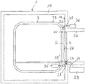
- FIG. 1 shows a schematic sectional view of an embodiment of a vacuum train system with an example of the door system for the vacuum train.
- a vacuum train 1 comprises basically a vehicle and a track for the vehicle which is designed as a pipe (or tunnel) from which the air has been partially or completely evacuated to reduce or eliminate aerodynamic drag. With magnetic levitation (or similar means) rolling resistance can also be eliminated. An outstanding performance and efficiency becomes possible.
- the cabin of the vehicle is obviously pressurised to a level which is comfortable for the passengers and crew (1.0 Bar).
- a vacuum train is shown in a much simplified schematic view in order to explain the basic features. Accordingly, the vacuum train 1 includes at least one vehicle 3 with a passenger cabin 13.
- This vehicle can be propelled and guided in the pipes or tunnel by a MAGLEV system (Magnetic Levitation system) or by any other suitable means.
- the MAGLEV system respectively the system for propulsion and guidance is not shown in the drawing.
- the present invention for the door system will work with any system. Together with the pipes and/or tunnels 10 in which the vehicle is travelling, the MAGLEV system resp. the system for propulsion and guidance forms the track of the vacuum train. At some points along the track there will be stations to allow passengers and goods to enter and exit the vehicles. To this end, doors 2 on the vehicle and doors 4 at the station are provided, which are only schematically indicated in the Figure. Obviously, at standstill at the station, the door or doors of the vehicle align with the door or doors of the station.
- the vehicle remains in the vacuum of the pipes at the stations.
- the gap between the vehicle and the inside walls of the pipes is sealed off during the boarding process at each door by at least one inflatable seal to prevent air from the station to seep into the vacuum in the pipes. Doors permits short boarding processes and short standstill times at stations. This is an important physical consequence of the chosen construction as shown below.
- the vehicle must wait in the station until the vacuum pressure between the vehicle door and the corresponding station door has been reduced to the low pressure or vacuum, respectively, in the pipes.
- the design and underlying principles of the door system for the vacuum train according to the present invention is illustrated in the following by an example of the door system as shown in the Figure. It shows the vehicle 3 stopped so that its door 2 is exactly aligned with the door 4 of the station 20. This of course applies as well if there are several vehicle doors and several station doors.
- vehicle door seal 21 which may be a pneumatically inflatable and deflatable seal or a fixed seal.
- station door seal 24 which may be a pneumatically inflatable and deflatable seal or a fixed seal.
- two inflatable and deflatable ring-shaped seals 22 are provided, which are positioned to surround both doors when the doors are in their corresponding position and which in their inflated state as shown seal both doors and the space 26 between the doors against the vacuum within the pipe by filling the gap between the vehicle outer surface 33 and the inner pipe wall 11 at the station and which do not fill the gap when being in their deflated state.
- the (pneumatically) inflatable and deflatable ring-shaped seals 22 can be inflated by at least one pump 36 connected to the pneumatic seal 22 through channels 35 of which only one channel is indicated in the Figure. This applies to the pneumatic ring-shaped seal 22 which is part of the station.
- a pump 36' and one channel 35' are indicated in the Figure at the vehicle below the passenger floor.
- Inflation of the inflatable seals 22 can as well be done via a tank filled with compressed gas, in particular compressed air, instead of or in addition to a pump. Deflation of the seals can be done via at least one valve (not shown) which opens up channels 35 and/or 35' so that the compressed gas within the seal will exit. Deflation can also be helped by at least one pump.
- the invention shown here satisfies the requirements of a modern high-speed transportation system and allows much shorter standstill times than the concept of a so-called airlock.
- This is a chamber into which the vehicle is introduced after the boarding process has taken place in a station under normal atmospheric conditions. It is then sealed off at the ends and aligned with a select vacuum pipe (track), into which the vehicle is transferred for travel to its chosen destination. In this way, only the layer of air immediately surrounding the vehicle (t ⁇ 10 cm) has to be evacuated before the transfer.
- the first option for reducing the pump-down time and consequently the stand-still times at stations is to minimise the volume V, which has to be evacuated.
- the vacuum train doors capture an air volume, V, of 0.2 m 3 between them and this only requires a pump-down time of about 22 seconds. This is a suitable match for the speed of a vacuum train. It can be 100 to 400 times quicker than the airlock solution shown above. As an option for the airlock solution, more pumps can be used but the total pumping speed will have to be increased by factor 100 respectively 400. This would be an unnecessary waste.
- the vacuum train door shown here is not only many times quicker. It would also be much simpler and much cheaper.
- a door system according to the present invention will be a necessity for vacuum trains. They offer short standstill times in the stations and contribute to the short overall travel times expected for vactrains.
- Airlocks make little or no sense, considering that vactrain doors according to the present invention are many times quicker and cheaper. They are too slow and do not match the speed requirements of vacuum trains.
Landscapes
- Engineering & Computer Science (AREA)
- Mechanical Engineering (AREA)
- Transportation (AREA)
- Architecture (AREA)
- General Engineering & Computer Science (AREA)
- Civil Engineering (AREA)
- Structural Engineering (AREA)
- Physics & Mathematics (AREA)
- Fluid Mechanics (AREA)
- Seal Device For Vehicle (AREA)
- Specific Sealing Or Ventilating Devices For Doors And Windows (AREA)
- Platform Screen Doors And Railroad Systems (AREA)
Claims (3)
- Ein Vakuumzugsystem (1) mit mindestens einem Fahrzeug (3) mit mindestens einer Fahrzeugtür (2) und einem Gleis für das Fahrzeug, wobei das Gleis mindestens eine Vakuumröhre und/oder einen Vakuumtunnel (10) für das Fahrzeug und mindestens eine Station (20) außerhalb der Röhre und/oder des Tunnels mit mindestens einer Stationstür (4) umfasst, die innerhalb der Wand der Röhre und/oder des Tunnels angeordnet ist, um die Station selektiv zur Röhre und/oder zum Tunnel hin zu schliessen und zu öffnen, wobei die Fahrzeugtür und die Stationstür so angeordnet sind, dass sie sich in einer entsprechenden Position befinden, wenn sich das Fahrzeug in seiner Ruheposition an der Station befindet, so dass das Fahrzeug zugänglich ist, wenn die Fahrzeugtür und die Stationstür in der Ruheposition des Fahrzeugs geöffnet sind, und mindestens eine aufblasbare und entleerbare ringförmige Dichtung (22) umfasst, die so positioniert ist, dass sie die Fahrzeugtür und die Stationstür (2, 4) umgibt, wenn sich die Türen in ihrer entsprechenden Position befinden, und die in ihrem aufgeblasenen Zustand, den Raum zwischen der Aussenfläche des Fahrzeugs (33) und der Wand der Röhre und/oder des Tunnels (11) an der Station ausfüllt und die beiden Türen (2, 4) und den Raum (26) zwischen den Türen gegen das Vakuum im Inneren der Röhren und/oder Tunnel abdichtet, und welche aufblasbare und entleerbare ringförmige Dichtung (22) den Raum nicht ausfüllt, wenn sie sich in ihrem entleerten Zustand befindet, wobei eine ringförmige Dichtung (22) dauerhaft um die Stationstür (4) herum angeordnet ist und durch mindestens eine Fluidpumpe (36) und/oder durch mindestens einen ausserhalb der Röhre und/oder des Tunnels angeordneten Druckgasbehälter aufblasbar ist, dadurch gekennzeichnet, dass eine zweite ringförmige Dichtung permanent um die Fahrzeugtür herum angeordnet ist und durch mindestens eine Fluidpumpe (36') und/oder durch einen Druckgasbehälter, der innerhalb des Fahrzeugs angeordnet ist, aufblasbar ist und der Durchmesser des Rings einer der beiden Dichtungen grösser ist als derjenige der anderen Dichtung, so dass die ringförmigen Dichtungen in radialer Richtung von der Mitte der Stationstür aus aufeinander folgen.
- Das Vakuumzugsystem nach Anspruch 1, wobei das Material oder die Materialkombination, aus dem bzw. der die ringförmige Dichtung (22) besteht, verstärkten Gummi umfasst und vorzugsweise zusätzlich eine äussere Schicht der Dichtung umfasst, die ein Kunststoffmaterial umfasst, das eine bessere Abdichtung der ringförmigen Dichtung gegen den Rumpf des Fahrzeugs und das Innere der Röhre oder des Tunnels im Vergleich zum Gummimaterial ermöglicht.
- Das Vakuumzugsystem nach einem der Ansprüche 1 oder 2, wobei an den Positionen, an denen die ringförmige Dichtung (22) in ihrem aufgeblasenen Zustand mit dem Rumpf des Fahrzeugs und dem Inneren der Röhre oder des Tunnels in Kontakt stehen wird, am Rumpf des Fahrzeugs und/oder am Inneren der Röhre oder des Tunnels ein Material vorgesehen ist, das die Dichtungseigenschaften der ringförmigen Dichtung gegenüber dem Fahrzeug und der Röhre oder dem Tunnel verbessert, und/oder wobei an den Positionen, an denen die ringförmige Dichtung in ihrem aufgeblasenen Zustand mit dem Rumpf des Fahrzeugs und dem Inneren der Röhre oder des Tunnels in Kontakt kommt, mindestens eine Nut am Rumpf des Fahrzeugs und/oder am Inneren der Röhre oder des Tunnels vorgesehen ist, die so angeordnet ist, dass sie den Kontakt der Dichtung mit dem Rumpf und/oder der Wand verbessert.
Applications Claiming Priority (1)
| Application Number | Priority Date | Filing Date | Title |
|---|---|---|---|
| PCT/EP2017/073310 WO2019052656A1 (en) | 2017-09-15 | 2017-09-15 | DOOR SYSTEM FOR A VACUUM TRAIN |
Publications (2)
| Publication Number | Publication Date |
|---|---|
| EP3672857A1 EP3672857A1 (de) | 2020-07-01 |
| EP3672857B1 true EP3672857B1 (de) | 2022-12-21 |
Family
ID=60327270
Family Applications (1)
| Application Number | Title | Priority Date | Filing Date |
|---|---|---|---|
| EP17797864.0A Active EP3672857B1 (de) | 2017-09-15 | 2017-09-15 | Vakuumzugsystem |
Country Status (10)
| Country | Link |
|---|---|
| US (1) | US11492018B2 (de) |
| EP (1) | EP3672857B1 (de) |
| JP (1) | JP2020533231A (de) |
| KR (1) | KR20200053491A (de) |
| CN (1) | CN111051176B (de) |
| AU (1) | AU2017431376C1 (de) |
| BR (1) | BR112020004653A2 (de) |
| CA (1) | CA3075551A1 (de) |
| RU (1) | RU2020109478A (de) |
| WO (1) | WO2019052656A1 (de) |
Families Citing this family (10)
| Publication number | Priority date | Publication date | Assignee | Title |
|---|---|---|---|---|
| US11319098B2 (en) * | 2017-03-31 | 2022-05-03 | The Boeing Company | Vacuum volume reduction system and method with fluid fill assembly for a vacuum tube vehicle station |
| EP3656644B1 (de) * | 2018-11-21 | 2026-03-18 | SpeedInnov | Schienenfahrzeug, das ein perfektioniertes system zum schutz gegen druckwellen umfasst |
| CN113895468B (zh) * | 2020-06-22 | 2023-03-14 | 中国航天科工飞航技术研究院(中国航天海鹰机电技术研究院) | 一种适用于真空管道高速磁悬浮列车的接驳廊桥 |
| CN115563904A (zh) * | 2022-11-07 | 2023-01-03 | 中车株洲电力机车有限公司 | 动态气密性的计算方法及相关组件 |
| US20240300547A1 (en) * | 2023-03-09 | 2024-09-12 | Hamilton Sundstrand Corporation | Hyperloop environmental control system |
| US12459548B2 (en) * | 2023-03-09 | 2025-11-04 | Hamilton Sundstrand Corporation | Hyperloop environmental control system |
| US20240300550A1 (en) * | 2023-03-09 | 2024-09-12 | Hamilton Sundstrand Corporation | Hyperloop environmental control system |
| US12522259B2 (en) * | 2023-03-09 | 2026-01-13 | Hamilton Sundstrand Corporation | Hyperloop environmental control system |
| CN120057042B (zh) * | 2025-02-20 | 2025-10-24 | 中铁第一勘察设计院集团有限公司 | 低真空隧道超高速列车连接用通道系统及其运行方法 |
| CN120251048B (zh) * | 2025-05-27 | 2025-08-15 | 沈阳品奇巴马克交通设备能源技术有限公司 | 一种全高型站台安全门 |
Family Cites Families (32)
| Publication number | Priority date | Publication date | Assignee | Title |
|---|---|---|---|---|
| DE207878C (de) | ||||
| US3178779A (en) * | 1962-06-28 | 1965-04-20 | North American Aviation Inc | Multi-cell inflatable seal |
| US3325042A (en) * | 1964-11-04 | 1967-06-13 | American Sterilizer Co | Inflatable seal |
| DE2213210A1 (de) * | 1972-03-16 | 1973-10-04 | Boes Christian | Vakuum-helium-rohrschnellbahn |
| US3840208A (en) * | 1973-05-10 | 1974-10-08 | A Schudel | Bubble-tight inflatable seal for butterfly valve with offset disc |
| DE2439032C3 (de) | 1974-08-14 | 1981-06-04 | G. Siempelkamp Gmbh & Co, 4150 Krefeld | Vorrichtung zum Stapeln und Entstapeln von plattenförmigem Gut im Zuge der Herstellung von Spanplatten, Faserplatten u.dgl. |
| DE2627518C3 (de) * | 1976-06-18 | 1979-09-13 | Wayss & Freytag Ag, 6000 Frankfurt | Schildschwanzdichtung für Vortriebsschilde |
| US4441278A (en) * | 1981-11-12 | 1984-04-10 | The Presray Corporation | Mounting for endless sealing strips |
| US4804173A (en) | 1985-06-03 | 1989-02-14 | Roberts Corporation | Method and apparatus for moving individual sheets from a stack of sheets |
| US5282424A (en) * | 1991-11-18 | 1994-02-01 | Neill Gerard K O | High speed transport system |
| US5653175A (en) * | 1995-09-15 | 1997-08-05 | Milligan; George Truett | Vacuum highway vehicle |
| DE19716039C2 (de) | 1997-04-17 | 2001-03-08 | Schuler Automation Gmbh & Co | Vorrichtung zum Überführen von plattenartigen Teilen aus einer ersten Position in eine zweite Position |
| US7792609B2 (en) | 2002-09-26 | 2010-09-07 | Trumpf Maschinen Austria Gmbh & Co. Kg. | Gripping device for manipulating device and method for operation thereof |
| FR2852277B1 (fr) * | 2003-03-12 | 2006-11-24 | Vehicule ferroviaire comprenant une porte d'intercirculation a joint d'etancheite gonflable et procede de realisation correspondant | |
| US7178810B1 (en) * | 2004-11-02 | 2007-02-20 | The Presray Corporation | Mounting arrangement for inflatable seals |
| US7487616B2 (en) * | 2005-04-05 | 2009-02-10 | Central Sales & Service, Inc. | Rail car door sealing gasket |
| DE102005050829A1 (de) | 2005-10-24 | 2007-04-26 | Karl Lindner | Bearbeitungsvorrichtung mit einem verfahrbaren Spindelantrieb |
| US20080000756A1 (en) | 2006-06-30 | 2008-01-03 | Behnke Merlin E | High speed linear pick-and-place |
| EP1902815A3 (de) | 2006-09-20 | 2008-04-30 | Grob, Margret | Bearbeitungslinie mit mehreren Transportvorrichtungen |
| ITMI20070968A1 (it) | 2007-05-11 | 2008-11-12 | Meccano System S R L | Apparecchiatura di carico/scarico in asservimento ad un centro di taglio di lastre. |
| DE102008032302A1 (de) | 2008-07-09 | 2010-01-14 | Weinmann Holzbausystemtechnik Gmbh | Vorrichtung zum Fördern eines Werkstücks |
| CN101823488A (zh) * | 2009-03-03 | 2010-09-08 | 刘忠臣 | 真空管道对接技术及永磁浮高速列车系统 |
| CN101879901B (zh) * | 2009-05-08 | 2012-06-13 | 宁波市镇海西门专利技术开发有限公司 | 真空管道交通的站台通道 |
| DE102009022784A1 (de) | 2009-05-19 | 2010-11-25 | Burkhardt Gmbh | Plattenbearbeitungsmaschine von Platten aus Stein, Holz, Metall und/oder deren Ersatzwerkstoffen |
| IT1394376B1 (it) | 2009-06-23 | 2012-06-15 | Biesse Spa | Macchina per la lavorazione di componenti di legno o simili |
| JP5236797B2 (ja) | 2011-12-02 | 2013-07-17 | フリースペースエンジニアリング株式会社 | ワーク加工用搬送システム |
| ITBO20120241A1 (it) | 2012-05-03 | 2013-11-04 | Biesse Spa | Metodo e macchina per la lavorazione di componenti di legno o simili |
| DE102012207818A1 (de) | 2012-05-10 | 2013-11-14 | Trumpf Sachsen Gmbh | Verfahren und Vorrichtung zum Trennen von Bearbeitungsprodukten an einer Werkzeugmaschine |
| CN104260729B (zh) * | 2014-09-12 | 2017-03-08 | 王昕鑫 | 一种磁浮隧道的抽吸保真装置及其方法 |
| KR101641164B1 (ko) | 2014-11-25 | 2016-07-20 | 유도스타자동화 주식회사 | 중량측정장치를 갖춘 다관절 로봇 |
| CN104528376A (zh) | 2014-12-20 | 2015-04-22 | 佛山振宣精密科技工业有限公司 | 一种电视机面板加工用物料输送装置 |
| US10247310B2 (en) * | 2016-09-22 | 2019-04-02 | Pawling Engineered Products Inc. | Self-retaining, easily removable pneumatic seal |
-
2017
- 2017-09-15 CA CA3075551A patent/CA3075551A1/en active Pending
- 2017-09-15 RU RU2020109478A patent/RU2020109478A/ru unknown
- 2017-09-15 US US16/643,868 patent/US11492018B2/en active Active
- 2017-09-15 KR KR1020207006937A patent/KR20200053491A/ko not_active Withdrawn
- 2017-09-15 CN CN201780094649.6A patent/CN111051176B/zh active Active
- 2017-09-15 BR BR112020004653-1A patent/BR112020004653A2/pt not_active Application Discontinuation
- 2017-09-15 WO PCT/EP2017/073310 patent/WO2019052656A1/en not_active Ceased
- 2017-09-15 JP JP2020514566A patent/JP2020533231A/ja active Pending
- 2017-09-15 EP EP17797864.0A patent/EP3672857B1/de active Active
- 2017-09-15 AU AU2017431376A patent/AU2017431376C1/en active Active
Also Published As
| Publication number | Publication date |
|---|---|
| WO2019052656A1 (en) | 2019-03-21 |
| CN111051176A (zh) | 2020-04-21 |
| RU2020109478A (ru) | 2021-10-15 |
| CA3075551A1 (en) | 2019-03-21 |
| BR112020004653A2 (pt) | 2020-09-24 |
| EP3672857A1 (de) | 2020-07-01 |
| US20200189620A1 (en) | 2020-06-18 |
| US11492018B2 (en) | 2022-11-08 |
| JP2020533231A (ja) | 2020-11-19 |
| AU2017431376A1 (en) | 2020-03-19 |
| AU2017431376B2 (en) | 2024-08-01 |
| AU2017431376C1 (en) | 2024-11-14 |
| KR20200053491A (ko) | 2020-05-18 |
| CN111051176B (zh) | 2023-11-07 |
Similar Documents
| Publication | Publication Date | Title |
|---|---|---|
| EP3672857B1 (de) | Vakuumzugsystem | |
| US10745160B2 (en) | Vacuum volume reduction system for a vacuum tube vehicle station | |
| CN109532850B (zh) | 一种用于真空管道磁悬浮车辆的旅客上下车通道 | |
| KR20110069391A (ko) | 튜브 철도 시스템의 진공 분할 관리 시스템 및 진공 차단막 장치 | |
| CN108545083A (zh) | 真空管道高速列车旅客乘降系统 | |
| WO2008043308A1 (en) | A super high-speed ralway train system traveling in a vacuum tunnel /tube | |
| US20230399030A1 (en) | A tube transport system for very high vehicle speeds, a specific tube assembly to achieve high vacuum, and method of operating a tube transport system | |
| CN110615009A (zh) | 一种超高速真空磁悬浮隧道防灾救援系统与救援方法 | |
| WO2019179308A1 (zh) | 一种管道局部减压包裹快速交通运输装置 | |
| WO2017153735A1 (en) | Chamber | |
| CN209617127U (zh) | 一种用于真空管道磁悬浮车辆的旅客上下车通道 | |
| CN104260729B (zh) | 一种磁浮隧道的抽吸保真装置及其方法 | |
| EP4103440B1 (de) | Andocken eines radfahrzeugs an eine station unter verwendung eines kniefahrwerksystems | |
| CN112590827A (zh) | 低真空管道的乘降系统、运行车辆及运输系统 | |
| KR960704753A (ko) | 비행선용 화물실(A cargo compartment for a lighter-than-air vehicle) | |
| US11319098B2 (en) | Vacuum volume reduction system and method with fluid fill assembly for a vacuum tube vehicle station | |
| CN216969630U (zh) | 真空管道高速磁浮交通具有真空度保持功能的站台门系统 | |
| CA3199847A1 (en) | Vacuum valve for a vacuum conveying system | |
| CN213973963U (zh) | 低真空管道的乘降系统、运行车辆及运输系统 | |
| CN212289820U (zh) | 交通运输系统 | |
| CA3193013A1 (en) | Vacuum valve for a vacuum transport system | |
| US20230383864A1 (en) | Modular vacuum valve system for a vacuum transport system | |
| CN110871815B (zh) | 真空管道运输系统 | |
| CN111923935B (zh) | 交通运输系统 | |
| CN121734122A (zh) | 一种用于真空管道磁悬浮列车的快速登舱装置及方法 |
Legal Events
| Date | Code | Title | Description |
|---|---|---|---|
| STAA | Information on the status of an ep patent application or granted ep patent |
Free format text: STATUS: UNKNOWN |
|
| STAA | Information on the status of an ep patent application or granted ep patent |
Free format text: STATUS: THE INTERNATIONAL PUBLICATION HAS BEEN MADE |
|
| PUAI | Public reference made under article 153(3) epc to a published international application that has entered the european phase |
Free format text: ORIGINAL CODE: 0009012 |
|
| STAA | Information on the status of an ep patent application or granted ep patent |
Free format text: STATUS: REQUEST FOR EXAMINATION WAS MADE |
|
| 17P | Request for examination filed |
Effective date: 20200324 |
|
| AK | Designated contracting states |
Kind code of ref document: A1 Designated state(s): AL AT BE BG CH CY CZ DE DK EE ES FI FR GB GR HR HU IE IS IT LI LT LU LV MC MK MT NL NO PL PT RO RS SE SI SK SM TR |
|
| AX | Request for extension of the european patent |
Extension state: BA ME |
|
| DAV | Request for validation of the european patent (deleted) | ||
| DAX | Request for extension of the european patent (deleted) | ||
| GRAP | Despatch of communication of intention to grant a patent |
Free format text: ORIGINAL CODE: EPIDOSNIGR1 |
|
| STAA | Information on the status of an ep patent application or granted ep patent |
Free format text: STATUS: GRANT OF PATENT IS INTENDED |
|
| INTG | Intention to grant announced |
Effective date: 20220719 |
|
| GRAS | Grant fee paid |
Free format text: ORIGINAL CODE: EPIDOSNIGR3 |
|
| GRAA | (expected) grant |
Free format text: ORIGINAL CODE: 0009210 |
|
| STAA | Information on the status of an ep patent application or granted ep patent |
Free format text: STATUS: THE PATENT HAS BEEN GRANTED |
|
| AK | Designated contracting states |
Kind code of ref document: B1 Designated state(s): AL AT BE BG CH CY CZ DE DK EE ES FI FR GB GR HR HU IE IS IT LI LT LU LV MC MK MT NL NO PL PT RO RS SE SI SK SM TR |
|
| REG | Reference to a national code |
Ref country code: GB Ref legal event code: FG4D |
|
| REG | Reference to a national code |
Ref country code: CH Ref legal event code: EP |
|
| REG | Reference to a national code |
Ref country code: DE Ref legal event code: R096 Ref document number: 602017064836 Country of ref document: DE |
|
| REG | Reference to a national code |
Ref country code: AT Ref legal event code: REF Ref document number: 1538897 Country of ref document: AT Kind code of ref document: T Effective date: 20230115 |
|
| REG | Reference to a national code |
Ref country code: IE Ref legal event code: FG4D |
|
| REG | Reference to a national code |
Ref country code: LT Ref legal event code: MG9D |
|
| REG | Reference to a national code |
Ref country code: NL Ref legal event code: MP Effective date: 20221221 |
|
| PG25 | Lapsed in a contracting state [announced via postgrant information from national office to epo] |
Ref country code: SE Free format text: LAPSE BECAUSE OF FAILURE TO SUBMIT A TRANSLATION OF THE DESCRIPTION OR TO PAY THE FEE WITHIN THE PRESCRIBED TIME-LIMIT Effective date: 20221221 Ref country code: NO Free format text: LAPSE BECAUSE OF FAILURE TO SUBMIT A TRANSLATION OF THE DESCRIPTION OR TO PAY THE FEE WITHIN THE PRESCRIBED TIME-LIMIT Effective date: 20230321 Ref country code: LT Free format text: LAPSE BECAUSE OF FAILURE TO SUBMIT A TRANSLATION OF THE DESCRIPTION OR TO PAY THE FEE WITHIN THE PRESCRIBED TIME-LIMIT Effective date: 20221221 Ref country code: FI Free format text: LAPSE BECAUSE OF FAILURE TO SUBMIT A TRANSLATION OF THE DESCRIPTION OR TO PAY THE FEE WITHIN THE PRESCRIBED TIME-LIMIT Effective date: 20221221 |
|
| REG | Reference to a national code |
Ref country code: AT Ref legal event code: MK05 Ref document number: 1538897 Country of ref document: AT Kind code of ref document: T Effective date: 20221221 |
|
| PG25 | Lapsed in a contracting state [announced via postgrant information from national office to epo] |
Ref country code: RS Free format text: LAPSE BECAUSE OF FAILURE TO SUBMIT A TRANSLATION OF THE DESCRIPTION OR TO PAY THE FEE WITHIN THE PRESCRIBED TIME-LIMIT Effective date: 20221221 Ref country code: LV Free format text: LAPSE BECAUSE OF FAILURE TO SUBMIT A TRANSLATION OF THE DESCRIPTION OR TO PAY THE FEE WITHIN THE PRESCRIBED TIME-LIMIT Effective date: 20221221 Ref country code: HR Free format text: LAPSE BECAUSE OF FAILURE TO SUBMIT A TRANSLATION OF THE DESCRIPTION OR TO PAY THE FEE WITHIN THE PRESCRIBED TIME-LIMIT Effective date: 20221221 Ref country code: GR Free format text: LAPSE BECAUSE OF FAILURE TO SUBMIT A TRANSLATION OF THE DESCRIPTION OR TO PAY THE FEE WITHIN THE PRESCRIBED TIME-LIMIT Effective date: 20230322 |
|
| P01 | Opt-out of the competence of the unified patent court (upc) registered |
Effective date: 20230515 |
|
| PG25 | Lapsed in a contracting state [announced via postgrant information from national office to epo] |
Ref country code: NL Free format text: LAPSE BECAUSE OF FAILURE TO SUBMIT A TRANSLATION OF THE DESCRIPTION OR TO PAY THE FEE WITHIN THE PRESCRIBED TIME-LIMIT Effective date: 20221221 |
|
| PG25 | Lapsed in a contracting state [announced via postgrant information from national office to epo] |
Ref country code: SM Free format text: LAPSE BECAUSE OF FAILURE TO SUBMIT A TRANSLATION OF THE DESCRIPTION OR TO PAY THE FEE WITHIN THE PRESCRIBED TIME-LIMIT Effective date: 20221221 Ref country code: RO Free format text: LAPSE BECAUSE OF FAILURE TO SUBMIT A TRANSLATION OF THE DESCRIPTION OR TO PAY THE FEE WITHIN THE PRESCRIBED TIME-LIMIT Effective date: 20221221 Ref country code: PT Free format text: LAPSE BECAUSE OF FAILURE TO SUBMIT A TRANSLATION OF THE DESCRIPTION OR TO PAY THE FEE WITHIN THE PRESCRIBED TIME-LIMIT Effective date: 20230421 Ref country code: ES Free format text: LAPSE BECAUSE OF FAILURE TO SUBMIT A TRANSLATION OF THE DESCRIPTION OR TO PAY THE FEE WITHIN THE PRESCRIBED TIME-LIMIT Effective date: 20221221 Ref country code: EE Free format text: LAPSE BECAUSE OF FAILURE TO SUBMIT A TRANSLATION OF THE DESCRIPTION OR TO PAY THE FEE WITHIN THE PRESCRIBED TIME-LIMIT Effective date: 20221221 Ref country code: CZ Free format text: LAPSE BECAUSE OF FAILURE TO SUBMIT A TRANSLATION OF THE DESCRIPTION OR TO PAY THE FEE WITHIN THE PRESCRIBED TIME-LIMIT Effective date: 20221221 Ref country code: AT Free format text: LAPSE BECAUSE OF FAILURE TO SUBMIT A TRANSLATION OF THE DESCRIPTION OR TO PAY THE FEE WITHIN THE PRESCRIBED TIME-LIMIT Effective date: 20221221 |
|
| PG25 | Lapsed in a contracting state [announced via postgrant information from national office to epo] |
Ref country code: SK Free format text: LAPSE BECAUSE OF FAILURE TO SUBMIT A TRANSLATION OF THE DESCRIPTION OR TO PAY THE FEE WITHIN THE PRESCRIBED TIME-LIMIT Effective date: 20221221 Ref country code: PL Free format text: LAPSE BECAUSE OF FAILURE TO SUBMIT A TRANSLATION OF THE DESCRIPTION OR TO PAY THE FEE WITHIN THE PRESCRIBED TIME-LIMIT Effective date: 20221221 Ref country code: IS Free format text: LAPSE BECAUSE OF FAILURE TO SUBMIT A TRANSLATION OF THE DESCRIPTION OR TO PAY THE FEE WITHIN THE PRESCRIBED TIME-LIMIT Effective date: 20230421 Ref country code: AL Free format text: LAPSE BECAUSE OF FAILURE TO SUBMIT A TRANSLATION OF THE DESCRIPTION OR TO PAY THE FEE WITHIN THE PRESCRIBED TIME-LIMIT Effective date: 20221221 |
|
| REG | Reference to a national code |
Ref country code: DE Ref legal event code: R097 Ref document number: 602017064836 Country of ref document: DE |
|
| PLBE | No opposition filed within time limit |
Free format text: ORIGINAL CODE: 0009261 |
|
| STAA | Information on the status of an ep patent application or granted ep patent |
Free format text: STATUS: NO OPPOSITION FILED WITHIN TIME LIMIT |
|
| PG25 | Lapsed in a contracting state [announced via postgrant information from national office to epo] |
Ref country code: DK Free format text: LAPSE BECAUSE OF FAILURE TO SUBMIT A TRANSLATION OF THE DESCRIPTION OR TO PAY THE FEE WITHIN THE PRESCRIBED TIME-LIMIT Effective date: 20221221 |
|
| 26N | No opposition filed |
Effective date: 20230922 |
|
| PG25 | Lapsed in a contracting state [announced via postgrant information from national office to epo] |
Ref country code: SI Free format text: LAPSE BECAUSE OF FAILURE TO SUBMIT A TRANSLATION OF THE DESCRIPTION OR TO PAY THE FEE WITHIN THE PRESCRIBED TIME-LIMIT Effective date: 20221221 |
|
| PG25 | Lapsed in a contracting state [announced via postgrant information from national office to epo] |
Ref country code: LU Free format text: LAPSE BECAUSE OF NON-PAYMENT OF DUE FEES Effective date: 20230915 |
|
| REG | Reference to a national code |
Ref country code: BE Ref legal event code: MM Effective date: 20230930 |
|
| PG25 | Lapsed in a contracting state [announced via postgrant information from national office to epo] |
Ref country code: LU Free format text: LAPSE BECAUSE OF NON-PAYMENT OF DUE FEES Effective date: 20230915 Ref country code: IT Free format text: LAPSE BECAUSE OF FAILURE TO SUBMIT A TRANSLATION OF THE DESCRIPTION OR TO PAY THE FEE WITHIN THE PRESCRIBED TIME-LIMIT Effective date: 20221221 Ref country code: MC Free format text: LAPSE BECAUSE OF FAILURE TO SUBMIT A TRANSLATION OF THE DESCRIPTION OR TO PAY THE FEE WITHIN THE PRESCRIBED TIME-LIMIT Effective date: 20221221 |
|
| REG | Reference to a national code |
Ref country code: IE Ref legal event code: MM4A |
|
| PG25 | Lapsed in a contracting state [announced via postgrant information from national office to epo] |
Ref country code: IE Free format text: LAPSE BECAUSE OF NON-PAYMENT OF DUE FEES Effective date: 20230915 |
|
| PG25 | Lapsed in a contracting state [announced via postgrant information from national office to epo] |
Ref country code: IE Free format text: LAPSE BECAUSE OF NON-PAYMENT OF DUE FEES Effective date: 20230915 |
|
| PG25 | Lapsed in a contracting state [announced via postgrant information from national office to epo] |
Ref country code: BE Free format text: LAPSE BECAUSE OF NON-PAYMENT OF DUE FEES Effective date: 20230930 |
|
| PG25 | Lapsed in a contracting state [announced via postgrant information from national office to epo] |
Ref country code: BG Free format text: LAPSE BECAUSE OF FAILURE TO SUBMIT A TRANSLATION OF THE DESCRIPTION OR TO PAY THE FEE WITHIN THE PRESCRIBED TIME-LIMIT Effective date: 20221221 |
|
| PG25 | Lapsed in a contracting state [announced via postgrant information from national office to epo] |
Ref country code: BG Free format text: LAPSE BECAUSE OF FAILURE TO SUBMIT A TRANSLATION OF THE DESCRIPTION OR TO PAY THE FEE WITHIN THE PRESCRIBED TIME-LIMIT Effective date: 20221221 |
|
| PG25 | Lapsed in a contracting state [announced via postgrant information from national office to epo] |
Ref country code: CY Free format text: LAPSE BECAUSE OF FAILURE TO SUBMIT A TRANSLATION OF THE DESCRIPTION OR TO PAY THE FEE WITHIN THE PRESCRIBED TIME-LIMIT; INVALID AB INITIO Effective date: 20170915 |
|
| PG25 | Lapsed in a contracting state [announced via postgrant information from national office to epo] |
Ref country code: HU Free format text: LAPSE BECAUSE OF FAILURE TO SUBMIT A TRANSLATION OF THE DESCRIPTION OR TO PAY THE FEE WITHIN THE PRESCRIBED TIME-LIMIT; INVALID AB INITIO Effective date: 20170915 |
|
| PGFP | Annual fee paid to national office [announced via postgrant information from national office to epo] |
Ref country code: DE Payment date: 20250818 Year of fee payment: 9 |
|
| PGFP | Annual fee paid to national office [announced via postgrant information from national office to epo] |
Ref country code: GB Payment date: 20250816 Year of fee payment: 9 |
|
| PGFP | Annual fee paid to national office [announced via postgrant information from national office to epo] |
Ref country code: FR Payment date: 20250816 Year of fee payment: 9 |
|
| PG25 | Lapsed in a contracting state [announced via postgrant information from national office to epo] |
Ref country code: TR Free format text: LAPSE BECAUSE OF FAILURE TO SUBMIT A TRANSLATION OF THE DESCRIPTION OR TO PAY THE FEE WITHIN THE PRESCRIBED TIME-LIMIT Effective date: 20221221 |
|
| REG | Reference to a national code |
Ref country code: CH Ref legal event code: U11 Free format text: ST27 STATUS EVENT CODE: U-0-0-U10-U11 (AS PROVIDED BY THE NATIONAL OFFICE) Effective date: 20251212 |
|
| PGFP | Annual fee paid to national office [announced via postgrant information from national office to epo] |
Ref country code: CH Payment date: 20251212 Year of fee payment: 9 |