EP3672840B1 - Belt assembly for a vehicle seat - Google Patents
Belt assembly for a vehicle seat Download PDFInfo
- Publication number
- EP3672840B1 EP3672840B1 EP18745872.4A EP18745872A EP3672840B1 EP 3672840 B1 EP3672840 B1 EP 3672840B1 EP 18745872 A EP18745872 A EP 18745872A EP 3672840 B1 EP3672840 B1 EP 3672840B1
- Authority
- EP
- European Patent Office
- Prior art keywords
- vehicle
- holding device
- belt
- seat
- vehicle seat
- Prior art date
- Legal status (The legal status is an assumption and is not a legal conclusion. Google has not performed a legal analysis and makes no representation as to the accuracy of the status listed.)
- Active
Links
- 230000001419 dependent effect Effects 0.000 claims description 4
- 230000014759 maintenance of location Effects 0.000 claims 1
- 238000005253 cladding Methods 0.000 description 4
- 230000000694 effects Effects 0.000 description 2
- 230000000712 assembly Effects 0.000 description 1
- 238000000429 assembly Methods 0.000 description 1
- 230000005540 biological transmission Effects 0.000 description 1
- 238000004891 communication Methods 0.000 description 1
- 230000008878 coupling Effects 0.000 description 1
- 238000010168 coupling process Methods 0.000 description 1
- 238000005859 coupling reaction Methods 0.000 description 1
- 238000011161 development Methods 0.000 description 1
- 230000018109 developmental process Effects 0.000 description 1
- 238000005516 engineering process Methods 0.000 description 1
- 230000000717 retained effect Effects 0.000 description 1
Images
Classifications
-
- B—PERFORMING OPERATIONS; TRANSPORTING
- B60—VEHICLES IN GENERAL
- B60R—VEHICLES, VEHICLE FITTINGS, OR VEHICLE PARTS, NOT OTHERWISE PROVIDED FOR
- B60R22/00—Safety belts or body harnesses in vehicles
- B60R22/18—Anchoring devices
- B60R22/20—Anchoring devices adjustable in position, e.g. in height
- B60R2022/208—Anchoring devices adjustable in position, e.g. in height by automatic or remote control means
-
- B—PERFORMING OPERATIONS; TRANSPORTING
- B60—VEHICLES IN GENERAL
- B60R—VEHICLES, VEHICLE FITTINGS, OR VEHICLE PARTS, NOT OTHERWISE PROVIDED FOR
- B60R22/00—Safety belts or body harnesses in vehicles
- B60R22/18—Anchoring devices
- B60R22/24—Anchoring devices secured to the side, door, or roof of the vehicle
Definitions
- the invention relates to a belt arrangement for a vehicle seat according to the preamble of claim 1. Furthermore, the invention relates to a vehicle with at least one vehicle seat and such a belt arrangement according to the preamble of claim 7.
- Airbags and belt assemblies are currently used in vehicles to protect occupants in an upright sitting position in an accident situation.
- Corresponding belt arrangements and vehicles are known in numerous variations.
- the belt arrangements can have a belt strap and at least one deflection element for the belt strap.
- the deflecting element can be arranged on a movably mounted holding device, wherein the deflection point of the belt strap can be adjustably supported on the vehicle by the holding device.
- novel belt arrangements are being developed and integrated in the vehicle.
- a holding device for a safety belt with manual position adjustment in the vertical direction of the vehicle is known, which is attached to a structure or a body of a vehicle, such as, for example, to a roof strut or a vehicle pillar.
- Motor vehicle with at least one seat and a seat belt system assigned to the seat comprising a belt strap fastened on one side to a belt attachment point, which is guided to a belt retractor via a deflection device arranged above the belt attachment point, the deflection device being guided by an associated Guide element is displaceably mounted, whereby the distance between the belt attachment point and the deflection device can be changed, wherein the guide element supports the deflection device in such a way that the distance between the belt attachment point and the deflection device by moving the deflection device starting from a maximum of this distance by at least 20% of the Can be shortened to a maximum and / or by at least 30 cm and / or by at least 30% of the distance between a seat surface of the seat and a roof of the vehicle interior of the motor vehicle.
- a seat arrangement for a vehicle which has at least one first row of seats with at least one driver's seat and one passenger seat and a second row of seats with at least one driver-side rear seat and one passenger-side rear seat.
- the passenger seat or the rear seat on the passenger side can be moved from a position of use into a position of non-use.
- the rear seat on the passenger side or the passenger seat can be displaced into a communication position in the resulting free space in such a way that the backrest of the passenger side rear seat or the passenger seat is located between the backrest of the driver's seat and the backrest of the driver's rear seat.
- the seat belt for the front passenger seat is connected to the vehicle body in the area of the roof pillar between the B-pillar and C-pillar of the vehicle by means of an articulated arm.
- the invention is based on the object of providing a belt arrangement for a vehicle and a vehicle with such a belt arrangement which, while driving, improves a restraint effect on an occupant who is sitting on a corresponding vehicle seat.
- a holding device which has a deflection element for a belt strap is rotatable about a pivot point a body element supported, wherein a drive rotates the holding device about the pivot point.
- the predetermined alignment of the holding device is dependent on the current inclination of the corresponding backrest.
- a belt arrangement is understood to mean a structural unit with the belt strap, by means of which the occupant is secured on the corresponding vehicle seat. This means that in an accident situation the belt strap ties the occupant to the vehicle seat and holds the occupant back in the vehicle seat.
- the belt arrangement can have elements such as deflection elements through which the belt webbing is guided, and fastening areas for the belt webbing, which are connected to a body. Alternatively, these elements can also be integrated into the vehicle seat.
- the belt strap is usually attached at its ends via the attachment areas to the vehicle body and / or a vehicle seat and can be deflected via the at least one deflection element.
- the belt arrangement can correspond to a three-point belt, in which the belt strap is coupled to the body at three connection points in an applied position. Alternatively, the belt arrangement can correspond to another known design with more than three connection points, for example a five-point belt.
- At least one vehicle seat is arranged in a corresponding vehicle, a position of the vehicle seat and an inclination of a seat back or backrest being adjustable.
- the inclination is understood here to be an angle between a seat surface and the backrest of the vehicle seat.
- a belt arrangement is assigned to each vehicle seat.
- the deflecting element arranged on the holding device can also be rotated about the pivot point.
- the course of the belt webbing which influences the restraint properties of the belt arrangement according to the invention, can be changed here.
- the alignment of the holding device and thereby the alignment of the deflecting element can be adapted automatically by the drive.
- the drive can fix the holding device in a predetermined orientation.
- the position of the deflecting element can be fixed in an advantageous manner and an undesired change in the position of the deflecting element due to forces acting can be reduced.
- the desired course of the belt webbing can advantageously also be retained in the accident situation, the belt webbing reliably tying the occupant to the vehicle seat.
- the holding device can be arranged on a vehicle pillar.
- the belt strap can for example run at least partially behind a panel of the vehicle pillar.
- the belt strap can run from a lower connection point designed as a belt retractor to the deflection point behind the cladding.
- the vehicle pillar can correspond to a B-pillar or a C-pillar or a D-pillar.
- the holding device and the pivot point can be mounted movably in the vertical direction of the vehicle and / or in the longitudinal direction of the vehicle.
- the holding device and the pivot point are moved along the vehicle pillar.
- a height adjustment and / or length adjustment of the at least one deflecting element can also take place by the height and / or length adjustment of the holding device, thereby taking into account different body sizes of the occupants and / or different positions of the vehicle seat and the connection the occupants of the vehicle seat can be further optimized.
- the holding device and the pivot point can be arranged on a telescopic arm which can be extended from the vehicle pillar and which moves the holding device in the vertical direction of the vehicle and / or in the longitudinal direction of the vehicle.
- a telescopic arm By extending and retracting the telescopic arm, an effective height and / or longitudinal adjustment of the position of the holding device and the position of the pivot point can advantageously take place even with so-called half vehicle pillars.
- At least one sensor can detect a change in the inclination of the backrest, the drive rotating the holding device around the pivot point as a function of the current inclination of the backrest.
- a corresponding alignment of the holding device can be automatically adopted for every inclination of the backrest.
- the alignment of the holding device can advantageously be adjusted promptly.
- the holding device can be arranged on the vehicle pillar and the drive can be arranged in the vehicle pillar.
- the drive can for example be arranged behind the cladding.
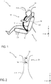
- a vehicle 1 has at least one vehicle seat 2 and a corresponding belt arrangement 10.
- a position of the at least one vehicle seat 2 and an inclination of a backrest 2.2 of the at least one vehicle seat 2 can be adjusted by the occupant 30.
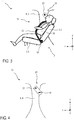
- Fig. 1 an upright starting position and in Fig. 3 an inclined comfort position of the vehicle seat 2 is shown.
- the belt arrangement 10 for the vehicle seat 2 comprises a belt strap 12 and at least one deflection element 14 for the belt strap 12, which is arranged on a movably mounted holding device 20.
- the holding device 20 is mounted on a body element 4 so as to be rotatable about a pivot point 22, a drive, which is not visible, rotates the holding device 20 about the pivot point 22.
- the illustrated embodiment of the belt arrangement 10 comprises a lower first connection point (not shown) designed as a belt retractor, an upper second connection point designed as a deflection element 14 and a belt buckle insertable into a belt lock 16.
- the belt buckle inserted into the belt lock 16 forms a third connection point and a second deflection point.
- the webbing 12 is guided by the webbing retractor, the deflecting element 14 and the belt buckle.
- the movable belt buckle can have an eyelet (not shown in greater detail), the belt buckle being threaded onto the belt strap 12 through the eyelet. In the operating state, the belt buckle forms a variable deflection.
- a cladding of the vehicle 1 according to the invention can be the belt strap 12 Cover at least partially between the lower connection point and the deflection element 14.
- the illustrated position of the belt strap 12 corresponds in each case to an operating position. In a rest position not shown, the belt buckle is not inserted into the belt lock 16.
- the non-visible drive can correspond to a screw drive, for example a worm drive.
- the transmission technology that transmits the power of the drive to the holding device 20 can also be covered by the cladding.
- the drive fixes the holding device 20 in a predetermined orientation. As a result, the position of the deflecting element 14 and the resulting belt webbing are also determined.
- a vehicle 1 according to the invention can have a plurality of vehicle seats 2.
- a belt arrangement 10 according to the invention is assigned to each vehicle seat 2. If the vehicle 1 according to the invention is able to drive autonomously, all vehicle seats 2 can have an in Fig. 3 Have the comfort position shown, which can be set individually by the respective occupant 30.
- the illustrated embodiment of the belt arrangement 10 relates to a three-point belt, wherein an embodiment as a five-point belt can also be imagined and implemented.
- the deflecting element 14 arranged on the holding device 20 corresponds to a stationary deflection which is arranged at head or shoulder height of the occupant 30.
- the holding device 20 is arranged on a vehicle pillar 6.
- the body element 4, around which the holding device 20 is rotatably mounted about the pivot point 22, is designed as a vehicle pillar 6.
- the holding device 20 and the pivot point 22 are movably supported in the vertical direction z of the vehicle and / or in the longitudinal direction x of the vehicle along the vehicle pillar 6.
- the position of the holding device 20 in the vertical direction of the vehicle z and / or in the vehicle longitudinal direction x is changed. This makes it possible to adapt the belt arrangement 10 according to the invention to a size of the occupant 30 and / or to a position of the vehicle seat 2.
- Figs. 1 to 4 It can also be seen that the predetermined alignment of the holding device 20 is dependent on a current inclination of the corresponding backrest 2.2. As a result, the position of the deflecting element 14 is adapted to the current inclination of the backrest 2.2 while driving, both in the vertical direction of the vehicle z and in the longitudinal direction of the vehicle x. This results in an early coupling of the belt webbing 12 to the occupant 30, as a result of which improved protection of the occupant 30 is possible.
- the holding device 20 and the pivot point 22 are arranged on a telescopic arm which can be extended out of the vehicle pillar 6 and which moves the holding device 20 in the vertical direction z of the vehicle.
- This design is particularly useful for vehicles 1 with half a B-pillar or half a C-pillar or for vehicles 1 without a B-pillar or without a C-pillar.
- At least one sensor can detect a change in the inclination of the backrest 2.2, the drive rotating the holding device 20 about the pivot point 22 as a function of the current inclination of the backrest 2.2.
- the holding device 20 can be arranged on the vehicle pillar 6 and the drive in the vehicle pillar 6.
Landscapes
- Engineering & Computer Science (AREA)
- Mechanical Engineering (AREA)
- Automotive Seat Belt Assembly (AREA)
Description
Die Erfindung betrifft eine Gurtanordnung für einen Fahrzeugsitz gemäß der Gattung des Patentanspruchs 1. Des Weiteren betrifft die Erfindung ein Fahrzeug mit mindestens einem Fahrzeugsitz und einer solchen Gurtanordnung gemäß der Gattung des Patentanspruchs 7.The invention relates to a belt arrangement for a vehicle seat according to the preamble of
Derzeit werden in Fahrzeugen Airbags und Gurtanordnungen eingesetzt, um Insassen in einer Unfallsituation in einer aufrechten Sitzposition zu schützen. Korrespondierende Gurtanordnungen und Fahrzeuge sind in zahlreichen Variationen bekannt. Die Gurtanordnungen können hierbei ein Gurtband und mindestens ein Umlenkelement für das Gurtband aufweisen. Das Umlenkelement kann an einer beweglich gelagerten Haltevorrichtung angeordnet werden, wobei der Umlenkpunkt des Gurtbands durch die Haltevorrichtung verstellbar am Fahrzeug gelagert werden kann. Um zukünftigen Anforderungen bei automatisiert fahrenden Fahrzeugen und daraus resultierenden Komfortstellungen der Fahrzeugsitze gerecht zu werden, werden neuartige Gurtanordnungen entwickelt und im Fahrzeug integriert.Airbags and belt assemblies are currently used in vehicles to protect occupants in an upright sitting position in an accident situation. Corresponding belt arrangements and vehicles are known in numerous variations. The belt arrangements can have a belt strap and at least one deflection element for the belt strap. The deflecting element can be arranged on a movably mounted holding device, wherein the deflection point of the belt strap can be adjustably supported on the vehicle by the holding device. In order to meet future requirements for automated vehicles and the resulting comfort positions of the vehicle seats, novel belt arrangements are being developed and integrated in the vehicle.
Aus der
Aus der
Aus der
Der Erfindung liegt die Aufgabe zu Grunde, eine Gurtanordnung für ein Fahrzeug und ein Fahrzeug mit einer solchen Gurtanordnung bereitzustellen, welche während der Fahrt eine Rückhaltewirkung auf einen Insassen verbessert, welcher auf einem korrespondierenden Fahrzeugsitz sitzt.The invention is based on the object of providing a belt arrangement for a vehicle and a vehicle with such a belt arrangement which, while driving, improves a restraint effect on an occupant who is sitting on a corresponding vehicle seat.
Diese Aufgabe wird durch eine Gurtanordnung mit den Merkmalen des Patentanspruchs 1 und durch ein Fahrzeug mit den Merkmalen des Patentanspruchs 7 gelöst. Vorteilhafte Ausgestaltungen mit zweckmäßigen Weiterbildungen der Erfindung sind in den abhängigen Patentansprüchen angegeben.This object is achieved by a belt arrangement with the features of
Um eine Gurtanordnung für ein Fahrzeug und ein Fahrzeug mit einer solchen Gurtanordnung bereitzustellen, welche eine Rückhaltewirkung auf einen Insassen während der Fahrt verbessert, welcher auf einem korrespondierenden Fahrzeugsitz sitzt, ist eine Haltevorrichtung, welche ein Umlenkelement für ein Gurtband aufweist, um einen Drehpunkt drehbar an einem Karosserieelement gelagert, wobei ein Antrieb die Haltevorrichtung um den Drehpunkt dreht. Hierbei ist die vorgegebene Ausrichtung der Haltevorrichtung von der aktuellen Neigung der korrespondierenden Rückenlehne abhängig. Dadurch kann in vorteilhafter Weise eine Lageveränderung der Rückenlehne in Fahrzeuglängsrichtung und in Fahrzeughochrichtung durch die Haltevorrichtung während der Fahrt ausgeglichen werden. Dadurch ist auch bei einer sehr flach eingestellten Rückenlehne ein Gurtbandverlauf umsetzbar, welcher den Insassen in vorteilhafter Weise sicher an den Fahrzeugsitz anbindet.In order to provide a belt arrangement for a vehicle and a vehicle with such a belt arrangement which improves a restraint effect on an occupant while driving who is sitting on a corresponding vehicle seat, a holding device which has a deflection element for a belt strap is rotatable about a pivot point a body element supported, wherein a drive rotates the holding device about the pivot point. The predetermined alignment of the holding device is dependent on the current inclination of the corresponding backrest. As a result, a change in position of the backrest in the longitudinal direction of the vehicle and in the vertical direction of the vehicle can be compensated for by the holding device while driving. As a result, even when the backrest is set very flat, a belt webbing can be implemented, which advantageously securely connects the occupant to the vehicle seat.
Unter einer Gurtanordnung wird im Folgenden eine Baueinheit mit dem Gurtband verstanden, über welches der Insasse auf dem korrespondierenden Fahrzeugsitz gesichert wird. Das heißt, dass das Gurtband in einer Unfallsituation den Insassen am Fahrzeugsitz anbindet und den Insassen im Fahrzeugsitz zurückhält. Hierbei kann die Gurtanordnung Elemente, wie beispielsweise Umlenkelemente, durch welche das Gurtband geführt ist, und Befestigungsbereiche für das Gurtband aufweisen, welche mit einer Karosserie verbunden sind. Alternativ können diese Elemente auch in den Fahrzeugsitz integriert werden. Üblicherweise ist das Gurtband an seinen Enden über die Befestigungsbereiche an der Fahrzeugkarosserie und/oder einem Fahrzeugsitz befestigt und über das mindestens eine Umlenkungselement umlenkbar. Die Gurtanordnung kann einem Dreipunktgurt entsprechen, bei welchem das Gurtband in einer angelegten Stellung an drei Anbindungspunkten mit der Karosserie gekoppelt ist. Alternativ kann die Gurtanordnung einer anderen bekannten Ausführung mit mehr als drei Anbindungspunkten entsprechen, beispielsweise einem Fünfpunktgurt.In the following, a belt arrangement is understood to mean a structural unit with the belt strap, by means of which the occupant is secured on the corresponding vehicle seat. This means that in an accident situation the belt strap ties the occupant to the vehicle seat and holds the occupant back in the vehicle seat. Here, the belt arrangement can have elements such as deflection elements through which the belt webbing is guided, and fastening areas for the belt webbing, which are connected to a body. Alternatively, these elements can also be integrated into the vehicle seat. The belt strap is usually attached at its ends via the attachment areas to the vehicle body and / or a vehicle seat and can be deflected via the at least one deflection element. The belt arrangement can correspond to a three-point belt, in which the belt strap is coupled to the body at three connection points in an applied position. Alternatively, the belt arrangement can correspond to another known design with more than three connection points, for example a five-point belt.
In einem korrespondierenden Fahrzeug ist mindestens ein Fahrzeugsitz angeordnet, wobei eine Position des Fahrzeugsitzes und eine Neigung einer Sitzlehne bzw. Rückenlehne einstellbar ist. Unter der Neigung wird hierbei ein Winkel zwischen einer Sitzfläche und der Rückenlehne des Fahrzeugsitzes verstanden. Jedem Fahrzeugsitz ist jeweils eine Gurtanordnung zugeordnet.At least one vehicle seat is arranged in a corresponding vehicle, a position of the vehicle seat and an inclination of a seat back or backrest being adjustable. The inclination is understood here to be an angle between a seat surface and the backrest of the vehicle seat. A belt arrangement is assigned to each vehicle seat.
In vorteilhafter Weise kann durch das Drehen der Haltevorrichtung um den Drehpunkt das an der Haltevorrichtung angeordnete Umlenkelement ebenfalls um den Drehpunkt gedreht werden. Hierbei kann der Gurtbandverlauf verändert werden, welcher die Rückhalteeigenschaften der erfindungsgemäßen Gurtanordnung beeinflusst. Durch den Antrieb kann die Ausrichtung der Haltevorrichtung und dadurch die Ausrichtung des Umlenkelements automatisiert angepasst werden.In an advantageous manner, by rotating the holding device about the pivot point, the deflecting element arranged on the holding device can also be rotated about the pivot point. The course of the belt webbing, which influences the restraint properties of the belt arrangement according to the invention, can be changed here. The alignment of the holding device and thereby the alignment of the deflecting element can be adapted automatically by the drive.
In vorteilhafter Ausgestaltung der erfindungsgemäßen Gurtanordnung kann der Antrieb die Haltevorrichtung in einer vorgegebenen Ausrichtung festlegen. Dadurch kann die Position des Umlenkelements in vorteilhafter Weise fixiert werden, und eine ungewollte Veränderung der Position des Umlenkelements durch wirkende Kräfte reduziert werden. Dadurch kann der gewünscht Gurtbandverlauf in vorteilhafter Weise auch in der Unfallsituation erhalten bleiben, wobei das Gurtband den Insassen zuverlässig am Fahrzeugsitz anbindet.In an advantageous embodiment of the belt arrangement according to the invention, the drive can fix the holding device in a predetermined orientation. As a result, the position of the deflecting element can be fixed in an advantageous manner and an undesired change in the position of the deflecting element due to forces acting can be reduced. As a result, the desired course of the belt webbing can advantageously also be retained in the accident situation, the belt webbing reliably tying the occupant to the vehicle seat.
In weiterer vorteilhafter Ausgestaltung der erfindungsgemäßen Gurtanordnung kann die Haltevorrichtung an einer Fahrzeugsäule angeordnet werden. Das Gurtband kann beispielsweise zumindest teilweise hinter einer Verkleidung der Fahrzeugsäule verlaufen. Beispielsweise kann das Gurtband von einem unteren als Gurtaufroller ausgeführten Anbindungspunkt zu dem Umlenkpunkt hinter der Verkleidung verlaufen. Die Fahrzeugsäule kann einer B-Säule oder einer C-Säule oder einer D-Säule entsprechen.In a further advantageous embodiment of the belt arrangement according to the invention, the holding device can be arranged on a vehicle pillar. The belt strap can for example run at least partially behind a panel of the vehicle pillar. For example, the belt strap can run from a lower connection point designed as a belt retractor to the deflection point behind the cladding. The vehicle pillar can correspond to a B-pillar or a C-pillar or a D-pillar.
In weiterer vorteilhafter Ausgestaltung der erfindungsgemäßen Gurtanordnung kann die Haltevorrichtung und der Drehpunkt in Fahrzeughochrichtung und/oder in Fahrzeuglängsrichtung bewegbar gelagert werden. Hierbei kann die Haltevorrichtung und der Drehpunkt entlang der Fahrzeugsäule bewegt werden. In vorteilhafter Weise kann eine Höhenverstellung und/oder Längsverstellung des mindestens einen Umlenkelements weiterhin durch die Höhen- und/oder Längsverstellung der Haltevorrichtung erfolgen, dadurch kann auf unterschiedliche Körpergrößen der Insassen und/oder auf unterschiedliche Positionen des Fahrzeugsitzes in vorteilhafter Weise Rücksicht genommen und die Anbindung der Insassen an den Fahrzeugsitz weiter optimiert werden.In a further advantageous embodiment of the belt arrangement according to the invention, the holding device and the pivot point can be mounted movably in the vertical direction of the vehicle and / or in the longitudinal direction of the vehicle. Here can the holding device and the pivot point are moved along the vehicle pillar. In an advantageous manner, a height adjustment and / or length adjustment of the at least one deflecting element can also take place by the height and / or length adjustment of the holding device, thereby taking into account different body sizes of the occupants and / or different positions of the vehicle seat and the connection the occupants of the vehicle seat can be further optimized.
In weiterer vorteilhafter Ausgestaltung der erfindungsgemäßen Gurtanordnung kann die Haltevorrichtung und der Drehpunkt an einem aus der Fahrzeugsäule ausfahrbaren Teleskoparm angeordnet werden, welcher die Haltevorrichtung in Fahrzeughochrichtung und/oder in Fahrzeuglängsrichtung bewegt. Durch das Ausfahren und Einfahren des Teleskoparms kann in vorteilhafter Weise eine effektive Höhen- und/oder Längsverstellung der Position der Haltevorrichtung und der Position des Drehpunkts auch bei sogenannten halben Fahrzeugsäulen erfolgen.In a further advantageous embodiment of the belt arrangement according to the invention, the holding device and the pivot point can be arranged on a telescopic arm which can be extended from the vehicle pillar and which moves the holding device in the vertical direction of the vehicle and / or in the longitudinal direction of the vehicle. By extending and retracting the telescopic arm, an effective height and / or longitudinal adjustment of the position of the holding device and the position of the pivot point can advantageously take place even with so-called half vehicle pillars.
In vorteilhafter Ausgestaltung des erfindungsgemäßen Fahrzeugs kann mindestens ein Sensor eine Veränderung der Neigung der Rückenlehne detektieren, wobei der Antrieb die Haltevorrichtung in Abhängigkeit der aktuellen Neigung der Rückenlehne um den Drehpunkt dreht. Dadurch kann zu jeder Neigung der Rückenlehne eine korrespondierende Ausrichtung der Haltevorrichtung automatisiert eingenommen werden. Zudem kann die Anpassung der Ausrichtung der Haltevorrichtung in vorteilhafter Weise zeitnah erfolgen.In an advantageous embodiment of the vehicle according to the invention, at least one sensor can detect a change in the inclination of the backrest, the drive rotating the holding device around the pivot point as a function of the current inclination of the backrest. As a result, a corresponding alignment of the holding device can be automatically adopted for every inclination of the backrest. In addition, the alignment of the holding device can advantageously be adjusted promptly.
In weiterer vorteilhafter Ausgestaltung des erfindungsgemäßen Fahrzeugs kann die Haltevorrichtung an der Fahrzeugsäule und der Antrieb in der Fahrzeugsäule angeordnet werden. Der Antrieb kann beispielsweise hinter der Verkleidung angeordnet werden. Dadurch unterscheidet sich die erfindungsgemäße Gurtanordnung für die Insassen von der äußeren Erscheinung kaum von bekannten Gurtanordnungen.In a further advantageous embodiment of the vehicle according to the invention, the holding device can be arranged on the vehicle pillar and the drive can be arranged in the vehicle pillar. The drive can for example be arranged behind the cladding. As a result, the belt arrangement according to the invention for the occupants hardly differs from known belt arrangements in terms of its external appearance.
Die für die erfindungsgemäße Gurtanordnung beschriebenen Vorteile und bevorzugten Ausführungsformen gelten auch für das erfindungsgemäße Fahrzeug.The advantages and preferred embodiments described for the belt arrangement according to the invention also apply to the vehicle according to the invention.
Die vorstehend in der Beschreibung genannten Merkmale und Merkmalskombinationen sowie die nachfolgend in der Figurenbeschreibung genannten und/oder in den Figuren alleine gezeigten Merkmale und Merkmalskombinationen sind nicht nur in der jeweils angegebenen Kombination, sondern auch in anderen Kombinationen oder in Alleinstellung verwendbar, ohne den Rahmen der Erfindung zu verlassen. Es sind somit auch Ausführungen als von der Erfindung umfasst und offenbart anzusehen, die in den Figuren nicht explizit gezeigt oder erläutert sind, jedoch durch separierte Merkmalskombinationen aus den erläuterten Ausführungen hervorgehen und erzeugbar sind.The features and combinations of features mentioned above in the description as well as the features and combinations of features mentioned below in the description of the figures and / or shown alone in the figures can be used not only in the respectively specified combination, but also in other combinations or on their own, without the scope of the Invention to leave. There are thus also embodiments to be regarded as encompassed and disclosed by the invention, which are not explicitly shown or explained in the figures, but emerge from the explained embodiments and can be generated by separate combinations of features.
Ein Ausführungsbeispiel der Erfindung ist in der Zeichnung dargestellt und wird in der nachfolgenden Beschreibung näher erläutert. In der Zeichnung bezeichnen gleiche Bezugszeichen Komponenten bzw. Elemente, die gleiche bzw. analoge Funktionen ausführen. Hierbei zeigt/zeigen:
- Fig. 1
- eine schematische Darstellung eines Ausschnitts eines erfindungsgemäßen Fahrzeugs mit einem Fahrzeugsitz und einer erfindungsgemäßen Gurtanordnung in einer Ausgangstellung;
- Fig. 2
- eine schematische Darstellung einer Haltevorrichtung der erfindungsgemäßen Gurtanordnung aus
Fig. 1 in der Ausgangstellung; - Fig. 3
- eine schematische Darstellung des erfindungsgemäßen Fahrzeugs und der erfindungsgemäßen Gurtanordnung aus
Fig. 1 in einer Komfortstellung; und - Fig. 4
- eine schematische Darstellung der Haltevorrichtung der erfindungsgemäßen Gurtanordnung aus
Fig. 3 in der Komfortstellung.
- Fig. 1
- a schematic representation of a section of a vehicle according to the invention with a vehicle seat and a belt arrangement according to the invention in an initial position;
- Fig. 2
- a schematic representation of a holding device of the belt arrangement according to the invention
Fig. 1 in the starting position; - Fig. 3
- a schematic representation of the vehicle according to the invention and the belt arrangement according to the invention
Fig. 1 in a comfort position; and - Fig. 4
- a schematic representation of the holding device of the belt arrangement according to the invention
Fig. 3 in the comfort position.
Wie aus
Wie aus
Erfindungsgemäß ist die Haltevorrichtung 20 um einen Drehpunkt 22 drehbar an einem Karosserieelement 4 gelagert, wobei ein nicht sichtbarer Antrieb die Haltevorrichtung 20 um den Drehpunkt 22 dreht.According to the invention, the holding
Wie aus
Ein nicht näher dargestelltes erfindungsgemäßes Fahrzeug 1 kann mehrere Fahrzeugsitze 2 aufweisen. Jedem Fahrzeugsitz 2 wird hierbei eine erfindungsgemäße Gurtanordnung 10 zugeordnet. Ist das erfindungsgemäße Fahrzeug 1 in der Lage autonom zu fahren, können während der Fahrt alle Fahrzeugsitze 2 eine in
Wie aus
Wie aus
Wie aus
In einem alternativen nicht dargestellten Ausführungsbeispiel der erfindungsgemäßen Gurtanordnung 10, sind die Haltevorrichtung 20 und der Drehpunkt 22 an einem aus der Fahrzeugsäule 6 ausfahrbaren Teleskoparm angeordnet, welcher die Haltevorrichtung 20 in Fahrzeughochrichtung z bewegt. Diese Ausführung ist insbesondere bei Fahrzeugen 1 mit halber B-Säule oder halber C-Säule oder bei Fahrzeugen 1 ohne B-Säule oder ohne C-Säule sinnvoll.In an alternative embodiment of the
Wie aus
- 11
- Fahrzeugvehicle
- 22
- FahrzeugsitzVehicle seat
- 2.22.2
- Rückenlehnebackrest
- 2.42.4
- SitzflächeSeat
- 44th
- KarosserieelementBody element
- 66th
- FahrzeugsäuleVehicle pillar
- 1010
- GurtanordnungBelt arrangement
- 1212
- GurtbandWebbing
- 1414th
- UmlenkelementDeflection element
- 1616
- GurtschlossSeat belt buckle
- 2020th
- HaltevorrichtungHolding device
- 2222nd
- Drehpunktpivot point
- 3030th
- Insasseinmate
- xx
- FahrzeuglängsrichtungVehicle longitudinal direction
- yy
- FahrzeugquerrichtungVehicle transverse direction
- zz
- FahrzeughochrichtungVehicle vertical direction
Claims (9)
- Belt arrangement (10) for a vehicle seat (2), having a belt strap (12) and at least one deflection element (14) for the belt strap (12), which is arranged on a movably mounted holding device (20) and ties a passenger (30) on the vehicle seat (2), in an accident situation, to the vehicle seat (2) and retains said passenger in the vehicle seat (2),
wherein the holding device (20) is mounted so as to rotate about a pivot point (22) on a body element (4), wherein a drive rotates the holding device (20) about the pivot point (22) and changes a profile of the belt strap (12) in order to influence the retention properties, wherein an orientation of the holding device (20) is dependent on a current inclination of a corresponding backrest (2.2) of the vehicle seat (2), such that a position change of the backrest (2.2) in the vehicle longitudinal direction (x) and in the vehicle vertical direction (z) can be compensated for by the holding device (20) during driving. - Belt arrangement according to claim 1,
characterised in that
the drive fixes the holding device (20) in a predetermined orientation. - Belt arrangement according to claim 1 or 2,
characterised in that
the holding device (20) is arranged on a vehicle pillar (6). - Belt arrangement according to any of claims 1 to 3,
characterised in that
the holding device (20) and the pivot point (22) are mounted so as to be movable in the vehicle vertical direction (z) and/or in the vehicle longitudinal direction (x). - Belt arrangement according to claim 3 or 4,
characterised in that
the holding device (20) and the pivot point (22) can be moved along the vehicle pillar (6). - Belt arrangement according to any of claims 3 to 5,
characterised in that
the holding device (20) and the pivot point (22) are arranged on a telescopic arm which can be extended out of the vehicle pillar (6) and which moves the holding device (20) in the vehicle vertical direction (z) and/or in the vehicle longitudinal direction (x). - Vehicle (1) having at least one vehicle seat (2) and a belt arrangement (10), wherein a position of the at least one vehicle seat (2) and an inclination of a backrest (2.2) of the at least one vehicle seat (2) are adjustable,
characterised in that
the belt arrangement (10) is designed according to at least one of claims 1 to 6. - Vehicle according to claim 7,
characterised in that
at least one sensor detects a change in the inclination of the backrest (2.2), wherein the drive rotates the holding device (20) about the pivot point (22) depending on the current inclination of the backrest (2.2). - Vehicle according to claim 7 or 8,
characterised in that
the holding device (20) is arranged on the vehicle pillar (6) and the drive is arranged in the vehicle pillar (6).
Applications Claiming Priority (2)
| Application Number | Priority Date | Filing Date | Title |
|---|---|---|---|
| DE102017008021.6A DE102017008021B4 (en) | 2017-08-24 | 2017-08-24 | Belt arrangement for a vehicle seat |
| PCT/EP2018/069710 WO2019037971A1 (en) | 2017-08-24 | 2018-07-20 | Belt assembly for a vehicle seat |
Publications (2)
| Publication Number | Publication Date |
|---|---|
| EP3672840A1 EP3672840A1 (en) | 2020-07-01 |
| EP3672840B1 true EP3672840B1 (en) | 2020-12-02 |
Family
ID=63014515
Family Applications (1)
| Application Number | Title | Priority Date | Filing Date |
|---|---|---|---|
| EP18745872.4A Active EP3672840B1 (en) | 2017-08-24 | 2018-07-20 | Belt assembly for a vehicle seat |
Country Status (4)
| Country | Link |
|---|---|
| EP (1) | EP3672840B1 (en) |
| CN (1) | CN110944882B (en) |
| DE (1) | DE102017008021B4 (en) |
| WO (1) | WO2019037971A1 (en) |
Families Citing this family (3)
| Publication number | Priority date | Publication date | Assignee | Title |
|---|---|---|---|---|
| DE102019008566B4 (en) * | 2019-12-11 | 2024-03-14 | Mercedes-Benz Group AG | Seat belt device |
| DE102023104524A1 (en) | 2023-02-24 | 2023-12-28 | Audi Aktiengesellschaft | Belt guide arrangement for a webbing of a vehicle seat |
| DE102023106691A1 (en) | 2023-03-17 | 2024-09-19 | Audi Aktiengesellschaft | Motor vehicle |
Family Cites Families (9)
| Publication number | Priority date | Publication date | Assignee | Title |
|---|---|---|---|---|
| FR2626826B2 (en) * | 1987-10-07 | 1991-05-24 | Ecia Equip Composants Ind Auto | HOLDING DEVICE FOR A SEAT BELT WITH MANUAL POSITION ADJUSTMENT |
| DE4001119A1 (en) * | 1990-01-17 | 1991-07-18 | Bayerische Motoren Werke Ag | Car bench seat safety belt - has screwed spindle adjusting coiling mechanisms dependent on number of passengers |
| DE19602021C1 (en) | 1996-01-20 | 1996-12-19 | Daimler Benz Ag | Bearing for safety belt deflector loop for motor vehicles |
| DE10021382A1 (en) | 2000-05-03 | 2001-11-08 | Takata Europ Gmbh | Seatbelt device for vehicle; has belt held on belt roller tensioned by spiral spring, with device to prevent belt from unrolling and belt guide device over passenger's shoulder to guide belt |
| DE102006021284A1 (en) | 2006-05-05 | 2007-11-08 | Johnson Controls Gmbh | Seating arrangement for a motor vehicle has a first row of seats with driver and co-driver seats and a second row of seats with backseats on the driver and co-driver sides |
| DE102011112831A1 (en) * | 2011-09-12 | 2013-03-14 | Trw Automotive Gmbh | Gurtbringersystem |
| DE102011113923A1 (en) | 2011-09-21 | 2013-03-21 | GM Global Technology Operations LLC (n. d. Gesetzen des Staates Delaware) | Motor vehicle has seat with swiveling backrest that swivels from vertical usage position into horizontal non-usage position and vice versa, where safety belt device is assigned to vehicle seat with safety belt |
| DE102014210302A1 (en) * | 2014-04-07 | 2015-10-08 | Brose Fahrzeugteile Gmbh & Co. Kg, Coburg | Method for adjusting a safety belt and adjustment device for a safety belt |
| DE102016015234B4 (en) * | 2016-12-21 | 2021-07-29 | Audi Ag | Motor vehicle with a seat belt system |
-
2017
- 2017-08-24 DE DE102017008021.6A patent/DE102017008021B4/en active Active
-
2018
- 2018-07-20 EP EP18745872.4A patent/EP3672840B1/en active Active
- 2018-07-20 WO PCT/EP2018/069710 patent/WO2019037971A1/en active Search and Examination
- 2018-07-20 CN CN201880047319.6A patent/CN110944882B/en active Active
Non-Patent Citations (1)
| Title |
|---|
| None * |
Also Published As
| Publication number | Publication date |
|---|---|
| WO2019037971A1 (en) | 2019-02-28 |
| EP3672840A1 (en) | 2020-07-01 |
| DE102017008021B4 (en) | 2021-07-29 |
| CN110944882A (en) | 2020-03-31 |
| CN110944882B (en) | 2022-07-05 |
| DE102017008021A1 (en) | 2019-02-28 |
Similar Documents
| Publication | Publication Date | Title |
|---|---|---|
| EP3519244B1 (en) | Seat system for a motor vehicle | |
| EP3672840B1 (en) | Belt assembly for a vehicle seat | |
| WO2019105959A1 (en) | Module base element for a vehicle occupant protection system and vehicle occupant protection system | |
| DE102017202644A1 (en) | Occupant protection device | |
| WO2005073033A1 (en) | Driver restraining system in a motor vehicle | |
| DE102015207882B4 (en) | A vehicle occupant protection device, motor vehicle, and method of operating a vehicle occupant protection device | |
| EP2189337B1 (en) | Safety device for vehicles | |
| DE3719656A1 (en) | Safety device for vehicles | |
| DE10209235B4 (en) | Safety device for a comfort seat | |
| DE102016015234B4 (en) | Motor vehicle with a seat belt system | |
| DE102020117211B4 (en) | Belt guidance system for a seat belt | |
| WO2019110477A1 (en) | Vehicle seat | |
| DE102019008566B4 (en) | Seat belt device | |
| WO2019048256A1 (en) | Vehicle seat and vehicle seat system for a motor vehicle | |
| DE102017007771B4 (en) | Method for operating an occupant protection device of an occupant protection device and occupant protection device | |
| DE102006056532B4 (en) | Vehicle with a belt guide element | |
| EP0024446B1 (en) | Safety belt arrangement for the occupants of vehicles, especially motor vehicles | |
| WO2016102032A1 (en) | Seat back for a vehicle seat, vehicle seat, and vehicle | |
| DE19522684A1 (en) | Safety belt system for seat in vehicles | |
| DE102009014390B4 (en) | Occupant restraint system | |
| EP3863888B1 (en) | Seat arrangement in a motor vehicle with a protection system for a passenger | |
| DE10340229B4 (en) | Safety device for locking a longitudinal seat offset | |
| DE10260400A1 (en) | Safety device for vehicle, especially motor vehicle, has force adjustment facility so retraining force can be set by a controller depending on detected maximum available displacement distance | |
| DE102023104524A1 (en) | Belt guide arrangement for a webbing of a vehicle seat | |
| DE102023106691A1 (en) | Motor vehicle |
Legal Events
| Date | Code | Title | Description |
|---|---|---|---|
| STAA | Information on the status of an ep patent application or granted ep patent |
Free format text: STATUS: UNKNOWN |
|
| STAA | Information on the status of an ep patent application or granted ep patent |
Free format text: STATUS: THE INTERNATIONAL PUBLICATION HAS BEEN MADE |
|
| PUAI | Public reference made under article 153(3) epc to a published international application that has entered the european phase |
Free format text: ORIGINAL CODE: 0009012 |
|
| STAA | Information on the status of an ep patent application or granted ep patent |
Free format text: STATUS: REQUEST FOR EXAMINATION WAS MADE |
|
| 17P | Request for examination filed |
Effective date: 20200324 |
|
| AK | Designated contracting states |
Kind code of ref document: A1 Designated state(s): AL AT BE BG CH CY CZ DE DK EE ES FI FR GB GR HR HU IE IS IT LI LT LU LV MC MK MT NL NO PL PT RO RS SE SI SK SM TR |
|
| AX | Request for extension of the european patent |
Extension state: BA ME |
|
| GRAP | Despatch of communication of intention to grant a patent |
Free format text: ORIGINAL CODE: EPIDOSNIGR1 |
|
| STAA | Information on the status of an ep patent application or granted ep patent |
Free format text: STATUS: GRANT OF PATENT IS INTENDED |
|
| DAV | Request for validation of the european patent (deleted) | ||
| DAX | Request for extension of the european patent (deleted) | ||
| INTG | Intention to grant announced |
Effective date: 20200921 |
|
| RIN1 | Information on inventor provided before grant (corrected) |
Inventor name: FUERST, FRANZ Inventor name: GRUNDHEBER, CHRISTOPH Inventor name: JAKOBS, BERND Inventor name: KROENES, WALTER |
|
| GRAS | Grant fee paid |
Free format text: ORIGINAL CODE: EPIDOSNIGR3 |
|
| GRAA | (expected) grant |
Free format text: ORIGINAL CODE: 0009210 |
|
| STAA | Information on the status of an ep patent application or granted ep patent |
Free format text: STATUS: THE PATENT HAS BEEN GRANTED |
|
| AK | Designated contracting states |
Kind code of ref document: B1 Designated state(s): AL AT BE BG CH CY CZ DE DK EE ES FI FR GB GR HR HU IE IS IT LI LT LU LV MC MK MT NL NO PL PT RO RS SE SI SK SM TR |
|
| REG | Reference to a national code |
Ref country code: GB Ref legal event code: FG4D Free format text: NOT ENGLISH |
|
| REG | Reference to a national code |
Ref country code: AT Ref legal event code: REF Ref document number: 1340580 Country of ref document: AT Kind code of ref document: T Effective date: 20201215 Ref country code: CH Ref legal event code: EP |
|
| REG | Reference to a national code |
Ref country code: IE Ref legal event code: FG4D Free format text: LANGUAGE OF EP DOCUMENT: GERMAN |
|
| REG | Reference to a national code |
Ref country code: DE Ref legal event code: R096 Ref document number: 502018003199 Country of ref document: DE |
|
| PG25 | Lapsed in a contracting state [announced via postgrant information from national office to epo] |
Ref country code: FI Free format text: LAPSE BECAUSE OF FAILURE TO SUBMIT A TRANSLATION OF THE DESCRIPTION OR TO PAY THE FEE WITHIN THE PRESCRIBED TIME-LIMIT Effective date: 20201202 Ref country code: RS Free format text: LAPSE BECAUSE OF FAILURE TO SUBMIT A TRANSLATION OF THE DESCRIPTION OR TO PAY THE FEE WITHIN THE PRESCRIBED TIME-LIMIT Effective date: 20201202 Ref country code: GR Free format text: LAPSE BECAUSE OF FAILURE TO SUBMIT A TRANSLATION OF THE DESCRIPTION OR TO PAY THE FEE WITHIN THE PRESCRIBED TIME-LIMIT Effective date: 20210303 Ref country code: NO Free format text: LAPSE BECAUSE OF FAILURE TO SUBMIT A TRANSLATION OF THE DESCRIPTION OR TO PAY THE FEE WITHIN THE PRESCRIBED TIME-LIMIT Effective date: 20210302 |
|
| REG | Reference to a national code |
Ref country code: NL Ref legal event code: MP Effective date: 20201202 |
|
| PG25 | Lapsed in a contracting state [announced via postgrant information from national office to epo] |
Ref country code: BG Free format text: LAPSE BECAUSE OF FAILURE TO SUBMIT A TRANSLATION OF THE DESCRIPTION OR TO PAY THE FEE WITHIN THE PRESCRIBED TIME-LIMIT Effective date: 20210302 Ref country code: PL Free format text: LAPSE BECAUSE OF FAILURE TO SUBMIT A TRANSLATION OF THE DESCRIPTION OR TO PAY THE FEE WITHIN THE PRESCRIBED TIME-LIMIT Effective date: 20201202 Ref country code: LV Free format text: LAPSE BECAUSE OF FAILURE TO SUBMIT A TRANSLATION OF THE DESCRIPTION OR TO PAY THE FEE WITHIN THE PRESCRIBED TIME-LIMIT Effective date: 20201202 Ref country code: SE Free format text: LAPSE BECAUSE OF FAILURE TO SUBMIT A TRANSLATION OF THE DESCRIPTION OR TO PAY THE FEE WITHIN THE PRESCRIBED TIME-LIMIT Effective date: 20201202 |
|
| PG25 | Lapsed in a contracting state [announced via postgrant information from national office to epo] |
Ref country code: NL Free format text: LAPSE BECAUSE OF FAILURE TO SUBMIT A TRANSLATION OF THE DESCRIPTION OR TO PAY THE FEE WITHIN THE PRESCRIBED TIME-LIMIT Effective date: 20201202 Ref country code: HR Free format text: LAPSE BECAUSE OF FAILURE TO SUBMIT A TRANSLATION OF THE DESCRIPTION OR TO PAY THE FEE WITHIN THE PRESCRIBED TIME-LIMIT Effective date: 20201202 |
|
| REG | Reference to a national code |
Ref country code: LT Ref legal event code: MG9D |
|
| PG25 | Lapsed in a contracting state [announced via postgrant information from national office to epo] |
Ref country code: SM Free format text: LAPSE BECAUSE OF FAILURE TO SUBMIT A TRANSLATION OF THE DESCRIPTION OR TO PAY THE FEE WITHIN THE PRESCRIBED TIME-LIMIT Effective date: 20201202 Ref country code: SK Free format text: LAPSE BECAUSE OF FAILURE TO SUBMIT A TRANSLATION OF THE DESCRIPTION OR TO PAY THE FEE WITHIN THE PRESCRIBED TIME-LIMIT Effective date: 20201202 Ref country code: CZ Free format text: LAPSE BECAUSE OF FAILURE TO SUBMIT A TRANSLATION OF THE DESCRIPTION OR TO PAY THE FEE WITHIN THE PRESCRIBED TIME-LIMIT Effective date: 20201202 Ref country code: EE Free format text: LAPSE BECAUSE OF FAILURE TO SUBMIT A TRANSLATION OF THE DESCRIPTION OR TO PAY THE FEE WITHIN THE PRESCRIBED TIME-LIMIT Effective date: 20201202 Ref country code: PT Free format text: LAPSE BECAUSE OF FAILURE TO SUBMIT A TRANSLATION OF THE DESCRIPTION OR TO PAY THE FEE WITHIN THE PRESCRIBED TIME-LIMIT Effective date: 20210405 Ref country code: RO Free format text: LAPSE BECAUSE OF FAILURE TO SUBMIT A TRANSLATION OF THE DESCRIPTION OR TO PAY THE FEE WITHIN THE PRESCRIBED TIME-LIMIT Effective date: 20201202 Ref country code: LT Free format text: LAPSE BECAUSE OF FAILURE TO SUBMIT A TRANSLATION OF THE DESCRIPTION OR TO PAY THE FEE WITHIN THE PRESCRIBED TIME-LIMIT Effective date: 20201202 |
|
| REG | Reference to a national code |
Ref country code: DE Ref legal event code: R097 Ref document number: 502018003199 Country of ref document: DE |
|
| PG25 | Lapsed in a contracting state [announced via postgrant information from national office to epo] |
Ref country code: IS Free format text: LAPSE BECAUSE OF FAILURE TO SUBMIT A TRANSLATION OF THE DESCRIPTION OR TO PAY THE FEE WITHIN THE PRESCRIBED TIME-LIMIT Effective date: 20210402 |
|
| PLBE | No opposition filed within time limit |
Free format text: ORIGINAL CODE: 0009261 |
|
| STAA | Information on the status of an ep patent application or granted ep patent |
Free format text: STATUS: NO OPPOSITION FILED WITHIN TIME LIMIT |
|
| PG25 | Lapsed in a contracting state [announced via postgrant information from national office to epo] |
Ref country code: AL Free format text: LAPSE BECAUSE OF FAILURE TO SUBMIT A TRANSLATION OF THE DESCRIPTION OR TO PAY THE FEE WITHIN THE PRESCRIBED TIME-LIMIT Effective date: 20201202 Ref country code: IT Free format text: LAPSE BECAUSE OF FAILURE TO SUBMIT A TRANSLATION OF THE DESCRIPTION OR TO PAY THE FEE WITHIN THE PRESCRIBED TIME-LIMIT Effective date: 20201202 |
|
| 26N | No opposition filed |
Effective date: 20210903 |
|
| PG25 | Lapsed in a contracting state [announced via postgrant information from national office to epo] |
Ref country code: SI Free format text: LAPSE BECAUSE OF FAILURE TO SUBMIT A TRANSLATION OF THE DESCRIPTION OR TO PAY THE FEE WITHIN THE PRESCRIBED TIME-LIMIT Effective date: 20201202 Ref country code: DK Free format text: LAPSE BECAUSE OF FAILURE TO SUBMIT A TRANSLATION OF THE DESCRIPTION OR TO PAY THE FEE WITHIN THE PRESCRIBED TIME-LIMIT Effective date: 20201202 |
|
| PG25 | Lapsed in a contracting state [announced via postgrant information from national office to epo] |
Ref country code: ES Free format text: LAPSE BECAUSE OF FAILURE TO SUBMIT A TRANSLATION OF THE DESCRIPTION OR TO PAY THE FEE WITHIN THE PRESCRIBED TIME-LIMIT Effective date: 20201202 |
|
| REG | Reference to a national code |
Ref country code: CH Ref legal event code: PL |
|
| PG25 | Lapsed in a contracting state [announced via postgrant information from national office to epo] |
Ref country code: MC Free format text: LAPSE BECAUSE OF FAILURE TO SUBMIT A TRANSLATION OF THE DESCRIPTION OR TO PAY THE FEE WITHIN THE PRESCRIBED TIME-LIMIT Effective date: 20201202 |
|
| REG | Reference to a national code |
Ref country code: BE Ref legal event code: MM Effective date: 20210731 |
|
| PG25 | Lapsed in a contracting state [announced via postgrant information from national office to epo] |
Ref country code: LI Free format text: LAPSE BECAUSE OF NON-PAYMENT OF DUE FEES Effective date: 20210731 Ref country code: CH Free format text: LAPSE BECAUSE OF NON-PAYMENT OF DUE FEES Effective date: 20210731 |
|
| PG25 | Lapsed in a contracting state [announced via postgrant information from national office to epo] |
Ref country code: IS Free format text: LAPSE BECAUSE OF FAILURE TO SUBMIT A TRANSLATION OF THE DESCRIPTION OR TO PAY THE FEE WITHIN THE PRESCRIBED TIME-LIMIT Effective date: 20210402 Ref country code: LU Free format text: LAPSE BECAUSE OF NON-PAYMENT OF DUE FEES Effective date: 20210720 |
|
| PG25 | Lapsed in a contracting state [announced via postgrant information from national office to epo] |
Ref country code: IE Free format text: LAPSE BECAUSE OF NON-PAYMENT OF DUE FEES Effective date: 20210720 Ref country code: BE Free format text: LAPSE BECAUSE OF NON-PAYMENT OF DUE FEES Effective date: 20210731 |
|
| PG25 | Lapsed in a contracting state [announced via postgrant information from national office to epo] |
Ref country code: CY Free format text: LAPSE BECAUSE OF FAILURE TO SUBMIT A TRANSLATION OF THE DESCRIPTION OR TO PAY THE FEE WITHIN THE PRESCRIBED TIME-LIMIT Effective date: 20201202 |
|
| P01 | Opt-out of the competence of the unified patent court (upc) registered |
Effective date: 20230530 |
|
| PG25 | Lapsed in a contracting state [announced via postgrant information from national office to epo] |
Ref country code: HU Free format text: LAPSE BECAUSE OF FAILURE TO SUBMIT A TRANSLATION OF THE DESCRIPTION OR TO PAY THE FEE WITHIN THE PRESCRIBED TIME-LIMIT; INVALID AB INITIO Effective date: 20180720 |
|
| PG25 | Lapsed in a contracting state [announced via postgrant information from national office to epo] |
Ref country code: MK Free format text: LAPSE BECAUSE OF FAILURE TO SUBMIT A TRANSLATION OF THE DESCRIPTION OR TO PAY THE FEE WITHIN THE PRESCRIBED TIME-LIMIT Effective date: 20201202 |
|
| REG | Reference to a national code |
Ref country code: AT Ref legal event code: MM01 Ref document number: 1340580 Country of ref document: AT Kind code of ref document: T Effective date: 20230720 |
|
| PG25 | Lapsed in a contracting state [announced via postgrant information from national office to epo] |
Ref country code: MT Free format text: LAPSE BECAUSE OF FAILURE TO SUBMIT A TRANSLATION OF THE DESCRIPTION OR TO PAY THE FEE WITHIN THE PRESCRIBED TIME-LIMIT Effective date: 20201202 |
|
| PGFP | Annual fee paid to national office [announced via postgrant information from national office to epo] |
Ref country code: DE Payment date: 20240731 Year of fee payment: 7 |
|
| PGFP | Annual fee paid to national office [announced via postgrant information from national office to epo] |
Ref country code: GB Payment date: 20240723 Year of fee payment: 7 |
|
| PGFP | Annual fee paid to national office [announced via postgrant information from national office to epo] |
Ref country code: FR Payment date: 20240724 Year of fee payment: 7 |
|
| PG25 | Lapsed in a contracting state [announced via postgrant information from national office to epo] |
Ref country code: AT Free format text: LAPSE BECAUSE OF NON-PAYMENT OF DUE FEES Effective date: 20230720 |
|
| PG25 | Lapsed in a contracting state [announced via postgrant information from national office to epo] |
Ref country code: AT Free format text: LAPSE BECAUSE OF NON-PAYMENT OF DUE FEES Effective date: 20230720 |