EP3672741B1 - Système d'entraînement et module d' une installation de profilage pour une installation de profilage - Google Patents
Système d'entraînement et module d' une installation de profilage pour une installation de profilage Download PDFInfo
- Publication number
- EP3672741B1 EP3672741B1 EP19783032.6A EP19783032A EP3672741B1 EP 3672741 B1 EP3672741 B1 EP 3672741B1 EP 19783032 A EP19783032 A EP 19783032A EP 3672741 B1 EP3672741 B1 EP 3672741B1
- Authority
- EP
- European Patent Office
- Prior art keywords
- module
- roller
- rollers
- modules
- profiling
- Prior art date
- Legal status (The legal status is an assumption and is not a legal conclusion. Google has not performed a legal analysis and makes no representation as to the accuracy of the status listed.)
- Active
Links
- 238000009434 installation Methods 0.000 title description 3
- 230000005540 biological transmission Effects 0.000 claims description 28
- 230000008878 coupling Effects 0.000 claims description 6
- 238000010168 coupling process Methods 0.000 claims description 6
- 238000005859 coupling reaction Methods 0.000 claims description 6
- 238000007493 shaping process Methods 0.000 claims description 5
- 239000002184 metal Substances 0.000 claims description 3
- 125000006850 spacer group Chemical group 0.000 claims description 3
- 238000004519 manufacturing process Methods 0.000 description 5
- 239000000314 lubricant Substances 0.000 description 2
- 238000003860 storage Methods 0.000 description 2
- 230000006978 adaptation Effects 0.000 description 1
- 230000001419 dependent effect Effects 0.000 description 1
- 230000010354 integration Effects 0.000 description 1
- 239000000463 material Substances 0.000 description 1
- 238000005259 measurement Methods 0.000 description 1
- 238000000034 method Methods 0.000 description 1
- 238000005192 partition Methods 0.000 description 1
- 238000004904 shortening Methods 0.000 description 1
Images

Classifications
-
- B—PERFORMING OPERATIONS; TRANSPORTING
- B21—MECHANICAL METAL-WORKING WITHOUT ESSENTIALLY REMOVING MATERIAL; PUNCHING METAL
- B21D—WORKING OR PROCESSING OF SHEET METAL OR METAL TUBES, RODS OR PROFILES WITHOUT ESSENTIALLY REMOVING MATERIAL; PUNCHING METAL
- B21D5/00—Bending sheet metal along straight lines, e.g. to form simple curves
- B21D5/06—Bending sheet metal along straight lines, e.g. to form simple curves by drawing procedure making use of dies or forming-rollers, e.g. making profiles
- B21D5/08—Bending sheet metal along straight lines, e.g. to form simple curves by drawing procedure making use of dies or forming-rollers, e.g. making profiles making use of forming-rollers
-
- B—PERFORMING OPERATIONS; TRANSPORTING
- B21—MECHANICAL METAL-WORKING WITHOUT ESSENTIALLY REMOVING MATERIAL; PUNCHING METAL
- B21D—WORKING OR PROCESSING OF SHEET METAL OR METAL TUBES, RODS OR PROFILES WITHOUT ESSENTIALLY REMOVING MATERIAL; PUNCHING METAL
- B21D5/00—Bending sheet metal along straight lines, e.g. to form simple curves
- B21D5/06—Bending sheet metal along straight lines, e.g. to form simple curves by drawing procedure making use of dies or forming-rollers, e.g. making profiles
- B21D5/10—Bending sheet metal along straight lines, e.g. to form simple curves by drawing procedure making use of dies or forming-rollers, e.g. making profiles for making tubes
- B21D5/12—Bending sheet metal along straight lines, e.g. to form simple curves by drawing procedure making use of dies or forming-rollers, e.g. making profiles for making tubes making use of forming-rollers
Definitions
- the present invention relates to a drive system for a profiling system for longitudinally shaping a metal strip or an initial profile into a profile or tube by means of a plurality of roller forming tools in the form of top rollers and bottom rollers, the top rollers being driven together and the bottom rollers being driven together.
- the invention also relates to a profiling module with such a drive system.
- Such a drive system for profiling systems is known, with drive means for a common drive of the upper rollers or lower rollers being arranged in an elongated cuboid housing and having a transmission input shaft on the longitudinal side of the housing opposite the upper rollers or lower rollers, and the drive means via a coupling via a common one Gearboxes can be driven with a drive motor.
- the spindles of the upper and lower rollers intervene directly in the drive means as an output shaft.
- This type of drive systems are designed in different lengths depending on the length and type of deformation of the objects to be deformed.
- the jointly driven upper rollers and lower rollers are driven by a motor and a common transmission, so that when the Costly adjustments result.
- such systems cannot simply be extended or shortened in length.
- the present invention is therefore based on the object of proposing a drive system that is suitable for a profiling system and, in particular, can be integrated into a profiling module and can be varied in a simple manner with regard to the length or the drive, depending on the user's wishes, with the integration into a profiling module, a profiling system of any length can be created depending on the choice.
- the drive system has gear output shafts for upper rollers and lower rollers, which are each mounted in an upper roller module or a lower roller module with an elongated cuboid housing.
- the respective roller module with which the upper roller module and the lower roller module are jointly referred to below, there are drive means for a common drive of the gear output shafts mounted in the roller module for the roller forming tools.
- the drive means in the cuboid housing can be designed in various ways, for example via a drive shaft with gear wheels for driving the individual gear output shafts for the roller forming tools or preferably via a chain of gear wheels directly on the gear output shafts for the roller forming tools.
- the roller modules thus have transmission output shafts protruding from the housing on one longitudinal side of the cuboid housing and openings for at least one transmission input shaft on the opposite side.
- This transmission input shaft can already be firmly integrated in the housing and protrude from the housing or can also be inserted into the corresponding opening when the motor drive is connected.
- the roller modules can each be arranged one above the other and detachably connected as a unit and can be arranged one on top of the other (upper roller module and lower roller module) and next to one another (lower roller module next to lower roller module or upper roller module next to upper roller module).
- the drive of one or more top roller modules can be operated separately from the drive of one or more top roller modules via corresponding clutches that are either plugged onto the outside of the gearbox input shaft or have an independent gearbox input shaft inserted into the opening of the housing several sub-roll modules can be realized. This makes it possible, depending on the requirements, to configure the drive unit in a simple manner and to provide it with only one drive or with a separate drive for the top rollers or the bottom rollers, which allows the roller forming tools to be optimally coordinated with one another.
- the respective roller modules i.e. all upper roller modules and all lower roller modules, can each be connected to a module connecting element that can be arranged outside the respective roller module.
- This can be more than two role modules.
- roller modules of different lengths or different roller modules with different spacings for the roller forming tools can be equipped.
- the roller modules have connecting shafts that protrude from the housing or are contained in the module connecting element and are inserted into openings provided for this purpose in the housing.
- roll modules can be provided in a profiling module that correspond approximately to half the width of the profiling module, so that the profiling module can be operated either with only one top roll module and one bottom roll module or with two top roll modules and two bottom roll modules.
- a further roller module can thus be connected in a driving manner in a simple manner through the upper roller module or lower roller module lying on one level.
- An appropriately equipped gear is located in the module connecting element.
- connection element is made from top roller module to top roller module or bottom roller module to bottom roller module.
- a corresponding configured module connection unit which can be arranged outside the respective housing of the roller module, an upper roller module can be connected to a lower roller module on the drive side. This is also done in such a way that it can either be plugged into the opening of the module housing from the outside, provided with corresponding connecting shafts, or conversely, it can be plugged onto connecting shafts protruding from the openings.
- a module connection unit is required when the upper roller modules and the lower roller modules are to be driven with only one drive unit and not separately from one another. If only one upper roller module and one lower roller module are used, the module connection element can be used as a module connection unit. This structure also enables the drive system to be configured easily in accordance with the wishes of the user.
- the top roller module with the gearbox input shaft also being able to be used as a bottom roller module and the top roller module without a gearbox input shaft also being able to be used as a bottom roller module.
- the individual roller modules are designed identically, so that an upper roller module can easily be operated as a lower roller module and vice versa.
- each roller module contains at least one opening to insert a transmission input shaft or already has a transmission input shaft. All roller modules are thus designed identically and differ only in that the corresponding opening in the housing on the side facing the drive is either closed or have transmission input shafts. It is the same with connecting shafts between the roller modules. This considerably simplifies production and reduces the costs for such a system.
- the roller modules can expediently be connected to one another via plug connections and can be fixed to one another. This can be done, for example, through openings provided in the housing and arranged on the top and bottom, through which connecting rods can be pushed, by means of which the roller modules can be screwed via corresponding threads provided on the connecting rods.
- This profiling module according to the invention for a profiling system is characterized by a drive system described above and is adapted to be able to implement a profiling system that can be adjusted depending on the application, in particular in length but also with regard to the roll forming tools, by stringing together a plurality of such profiling modules.
- a profiling module contains two upper roller modules arranged in one plane and two lower roller modules arranged in a plane below the upper roller modules, each of which is provided with a module connection element for the drive connection of the two upper roller modules and the two lower roller modules.
- a roll module size can be realized that is suitable for a profiling module that can be transported with a conventional truck.
- the use of two roller modules each also allows the removal of an upper roller module and a lower roller module if necessary, if a shortening or a change in the distances between the roller forming tools is necessary.
- a modular system for any number of profiling modules can be provided due to the resulting roll module size.
- the upper roller modules and the lower roller modules can be increased with the aid of spacer units and thus the vertical distance between the transmission output shafts between the upper roller module and the lower roller module can be increased individually.
- the upper roller modules and the lower roller modules are advantageously motor-driven and controllable separately from one another, so that the requirements of the profiling material can be optimally addressed.
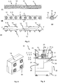
- Figure 1 shows the drive system 1 with two servomotors 2, 2 'in the exemplary game, which drive roller modules 5, 5', 6, 6 'via a motor gear 3, 3' and a coupling 4, 4 '.
- the upper roller modules 5, 5 ' are driven by the motor 2 and the lower roller modules 6, 6' are driven by the motor 2 '.
- the upper roller module 5 ' is shown removed from its operating position in this illustration.
- the role modules 5, 5 ', 6, 6' are further explained below in connection with the Figures 2 and 3 explained.
- the roller modules 5, 5 ', 6, 6' have an elongated housing 8 in which the in Figure 3 drive means shown are housed.
- the longitudinal housing side 13 on the drive side has non-visible openings from which, in this exemplary embodiment, the transmission input shaft 15 protrude for attachment to the clutch 4, 4 '.
- the housing 8 has transmission output shafts 7 which can be non-positively connected via intermediate pieces (not shown) in the usual manner to the corresponding roll forming tools, which are also not shown.
- a connecting shaft 16 protrudes from the housing 8 and is arranged as an extension of the corresponding transmission output shaft 7.
- the connecting shaft 16 can also be the transmission output shaft 7 at the same time.
- the connecting shaft 16 is used to couple a module connecting element 9, 9 'in order to drive the upper roller modules 5, 5' or the lower roller modules 6, 6 'to one another in this way.
- the connecting shaft 16 protrudes from the housing 8 and is inserted into a corresponding opening 29 in the respective module connecting element 9, 9 ′.
- the connecting shaft 16 is arranged in the module connecting element 9, 9 ′.
- the upper roller modules 5, 5 ' are firmly connected to the lower roller modules 6, 6' by means of screw connections via connecting pins 10, which are provided through openings 11 in the housings 8 of the roller modules 5, 5 ', 6, 6'.
- FIG. 2 shows the roller modules 5, 5 ', 6, 6' already explained above and the module connecting elements 9, 9 '.
- the figures show the housing 8 with the housing tops 14 and the openings 11 for the connecting pins 10, which can be pushed through the housing 8.
- the transmission input shaft 15 protruding from the housing 8 and the connecting shaft 16 in the upper roller module 5 and the lower roller module 6 can be seen.
- the upper roller module 5 'and the lower roller module 6' only have the connecting shaft 16 for coupling to the corresponding driven upper roller module 5 or lower roller module 6.
- there are thus two different roller modules the upper roller module with the lower roller module 6 or the upper roller module 5 'with the lower roller module 6' being easily exchanged.
- the roller modules 5, 5 ', 6, 6' are basically constructed in the same way, and are either closed by closing the respective opening provided in the longitudinal side 13 of the housing or by inserting gear input shafts 15 or connecting shaft 16 with regard to the use of the respective roller module 5, 5 ' , 6, 6 'set.
- the module connecting elements 9, 9 ' have gear wheels (not shown) inside for transmitting the drive forces between the upper roller modules 5, 5' and lower roller modules 6, 6 '.
- FIG 3 shows in the Figures 3A to 3D the elements already described above again in detail a roller module 5, 6 (in this exemplary embodiment) as it can, however, also be used for the roller modules 5 ', 6'.
- the transmission output shafts 7 are rotated by means of gear wheels 18 arranged next to one another in the housing 8 and arranged on the transmission output shafts 7, only one gear wheel 18 ′ being driven via the transmission input shaft 15 becomes.
- spacing elements not shown
- the drive system in Figure 1 uses two motors 2, 2 '. In principle, it is also possible to operate the drive system with just one drive motor, with the arrangement as in Figure 1 or in Figure 2 shown, on the connecting shafts 16 an in Figure 4
- the module connection unit 19 shown with four openings 30 with a connecting gear arranged therein is attached, so that the drive in this embodiment according to FIG Figure 1 takes place only with the motor 2 via the top roller module 5 for all other roller modules 5, 6, 6 '. If only one upper roller module 5 and one lower roller module 6 or one lower roller module 6 ′ is used in a drive with the motor 2, a module connection element 9, 9 ′ can be used instead of the module connection unit 19.
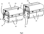
- FIG. 5 shows, in perspective, two profiling modules 20, 20 ', in which such a drive system as shown in FIGS Figures 1 to 4 is shown, is integrated and which have the same structure.
- Each profiling module 20, 20 ' can be seen to have a cover hood 21 via which the transmission output shafts for coupling the schematically illustrated roll forming tools 17 and the area in which the forming takes place are accessible.
- the covering hood 21 serves to cover a work / production area 22 and is articulated to a housing 33 surrounding the drive area 23.
- the drive area 23, in which the motors 2, 2 ', motor gears 3, 3' and clutch 4, 4 'and the drive system 1 are accommodated, is arranged behind it as seen from the operator's side.
- the roller modules 5, 5 'and 6, 6' are located in the drive area 23 and the roller forming tools 17 that can be connected to the roller modules are located in the work / production area 22 and are passed through the partition 35 via intermediate pieces 34 from the gear output shafts 7 of the roller modules 5, 5 'or 6, 6' driven.
- the profiling module 20 also has a supply area 24 below the work / production area 22 and the drive area 23 for laying cables with structured duct systems for separate laying of lines and hoses. In front of it there is a storage area 25 for additional accessories such as, for example, lubricant devices in the form of a lubricant pan 27, a computer system for recording measurement data, etc. Underneath there is an installation and transport area 31.
- a drawer 28 and also a folding compartment 32 are provided as a tool storage area in this area.
- the profiling modules 20, which are independent operational units, can be connected to a system control (not shown) and selected via a program, can be connected to other profiling modules 20 on both sides and inserted into the profiling system or easily removed from it.
Landscapes
- Engineering & Computer Science (AREA)
- Mechanical Engineering (AREA)
- Rollers For Roller Conveyors For Transfer (AREA)
- Rolls And Other Rotary Bodies (AREA)
- Bending Of Plates, Rods, And Pipes (AREA)
Claims (9)
- Système d'entraînement (1) pour une installation de profilage servant à façonner longitudinalement une bande métallique ou un profilé de départ en un profilé ou tube au moyen d'une pluralité d'outils de façonnage à rouleaux (17) sous la forme de rouleaux supérieurs et de rouleaux inférieurs, les rouleaux supérieurs étant entraînés conjointement et les rouleaux inférieurs étant entraînés conjointement, au moins un module de rouleaux supérieurs (5, 5') et au moins un module de rouleaux inférieurs (6, 6') étant dotés d'un boîtier allongé parallélépipédique (8) dans lequel se trouvent des moyens d'entraînement (18) pour un entraînement commun des rouleaux supérieurs ou rouleaux inférieurs par des arbres de sortie de transmission (7, 7') pour les rouleaux supérieurs ou les rouleaux inférieurs qui sont montés respectivement dans l'au moins un module de rouleaux supérieurs (5, 5') et l'au moins un module de rouleaux inférieurs (6, 6') et dépassent d'un côté longitudinal de boîtier (12), et lequel module comprend un arbre d'entrée de transmission (15) sur le côté longitudinal de boîtier (13) opposé aux rouleaux supérieurs ou rouleaux inférieurs, l'au moins un module de rouleaux supérieurs (5, 5') et l'au moins un module de rouleaux inférieurs (6, 6') pouvant être superposés respectivement en tant qu'unité et pouvant être reliés de manière amovible l'un à l'autre et les arbres de sortie de transmission (7, 7') pour les rouleaux supérieurs et les rouleaux inférieurs pouvant être entraînés par un moteur d'entraînement (2) par le biais d'un embrayage (4) par l'intermédiaire d'une transmission commune (3) ou pouvant être entraînés séparément les uns des autres par un embrayage (4, 4'), une transmission (3, 3') et un moteur d'entraînement (2, 2') respectivement associés.
- Système d'entraînement (1) selon la revendication 1, caractérisé par un élément de liaison de module (9, 9') pouvant être disposé à l'extérieur du module de rouleaux respectif (5, 5' ; 6, 6'), élément à l'aide duquel les arbres de sortie de transmission respectifs (7') d'un premier module de rouleaux supérieurs (5) ou module de rouleaux inférieurs (6) peuvent être reliés, côté entraînement, aux arbres de sortie de transmission (7') d'un autre module de rouleaux supérieurs (5') ou module de rouleaux inférieurs (6').
- Système d'entraînement (1) selon la revendication 1 ou la revendication 2, caractérisé par une unité de liaison de module (19) pouvant être disposée à l'extérieur du module de rouleaux respectif (5, 5' ; 6, 6'), unité à l'aide de laquelle au moins un module de rouleaux supérieurs (5, 5') peut être relié à un module de rouleaux inférieurs (6, 6') côté entraînement.
- Système d'entraînement (1) selon l'une des revendications précédentes, caractérisé en ce que l'au moins un module de rouleaux supérieurs (5, 5') et l'au moins un module de rouleaux inférieurs (6, 6') sont construits de manière identique en termes de structure et de manière identique au boîtier (8).
- Système d'entraînement (1) selon l'une des revendications précédentes, caractérisé en ce que l'au moins un module de rouleaux supérieurs (5, 5') et l'au moins un module de rouleaux inférieurs (6, 6') peuvent être reliés et fixés les uns aux autres par le biais de liaisons enfichables (10).
- Module de profilage (20) pour une installation de profilage servant à façonner longitudinalement une bande métallique ou un profilé de départ en un profilé ou tube au moyen d'une pluralité d'outils de façonnage à rouleaux (17) sous la forme de rouleaux supérieurs et de rouleaux inférieurs, les rouleaux supérieurs étant entraînés conjointement et les rouleaux inférieurs étant entraînés conjointement, caractérisé par un système d'entraînement (1) selon l'une des revendications précédentes.
- Module de profilage (20) selon la revendication 6, caractérisé en ce que deux modules de rouleaux supérieurs 85, 5') disposés dans un plan et deux modules de rouleaux inférieurs (6, 6') disposés dans un plan en dessous des modules de rouleaux supérieurs (5, 5'), lesquels sont dotés respectivement d'un élément de liaison de module (9, 9') pour la liaison par entraînement des deux modules de rouleaux supérieurs (5, 5') et des deux modules de rouleaux inférieurs (6, 6').
- Module de profilage (20) selon la revendication 7, caractérisé en ce que les modules de rouleaux supérieurs (5, 5') et les modules de rouleaux inférieurs (6, 6') sont entraînés de manière motorisée et peuvent être commandés séparément les uns des autres.
- Module de profilage (20) selon l'une des revendications précédentes 6 à 8, caractérisé en ce que les modules de rouleaux supérieurs (5, 5') et les modules de rouleaux inférieurs (6, 6') peuvent être élevés à l'aide d'unités d'espacement.
Priority Applications (1)
| Application Number | Priority Date | Filing Date | Title |
|---|---|---|---|
| PL19783032T PL3672741T3 (pl) | 2018-10-22 | 2019-10-08 | Układ napędowy i moduł profilujący do instalacji profilującej |
Applications Claiming Priority (2)
| Application Number | Priority Date | Filing Date | Title |
|---|---|---|---|
| EP18201776.4A EP3643420A1 (fr) | 2018-10-22 | 2018-10-22 | Système d'entraînement et module d' une installation de profilage pour une installation de profilage |
| PCT/EP2019/077173 WO2020083635A1 (fr) | 2018-10-22 | 2019-10-08 | Système d'entraînement et module de profilage pour une installation de profilage |
Publications (2)
| Publication Number | Publication Date |
|---|---|
| EP3672741A1 EP3672741A1 (fr) | 2020-07-01 |
| EP3672741B1 true EP3672741B1 (fr) | 2021-05-05 |
Family
ID=63965257
Family Applications (2)
| Application Number | Title | Priority Date | Filing Date |
|---|---|---|---|
| EP18201776.4A Withdrawn EP3643420A1 (fr) | 2018-10-22 | 2018-10-22 | Système d'entraînement et module d' une installation de profilage pour une installation de profilage |
| EP19783032.6A Active EP3672741B1 (fr) | 2018-10-22 | 2019-10-08 | Système d'entraînement et module d' une installation de profilage pour une installation de profilage |
Family Applications Before (1)
| Application Number | Title | Priority Date | Filing Date |
|---|---|---|---|
| EP18201776.4A Withdrawn EP3643420A1 (fr) | 2018-10-22 | 2018-10-22 | Système d'entraînement et module d' une installation de profilage pour une installation de profilage |
Country Status (4)
| Country | Link |
|---|---|
| EP (2) | EP3643420A1 (fr) |
| ES (1) | ES2887955T3 (fr) |
| PL (1) | PL3672741T3 (fr) |
| WO (1) | WO2020083635A1 (fr) |
Family Cites Families (4)
| Publication number | Priority date | Publication date | Assignee | Title |
|---|---|---|---|---|
| US4831857A (en) * | 1988-03-18 | 1989-05-23 | Tishken Products Co. | Machine with quick disconnect between spindle drive train and power transmission |
| US6053022A (en) * | 1998-09-14 | 2000-04-25 | Morgan Construction Company | Modular rolling mill |
| AT515177B1 (de) * | 2013-12-10 | 2015-08-15 | Asmag Holding Gmbh | Antriebssystem sowie damit ausgerüstete Profilieranlage |
| CN203695670U (zh) * | 2014-02-20 | 2014-07-09 | 杭州一波机械有限公司 | C/z檩条互换生产线 |
-
2018
- 2018-10-22 EP EP18201776.4A patent/EP3643420A1/fr not_active Withdrawn
-
2019
- 2019-10-08 EP EP19783032.6A patent/EP3672741B1/fr active Active
- 2019-10-08 PL PL19783032T patent/PL3672741T3/pl unknown
- 2019-10-08 WO PCT/EP2019/077173 patent/WO2020083635A1/fr unknown
- 2019-10-08 ES ES19783032T patent/ES2887955T3/es active Active
Also Published As
| Publication number | Publication date |
|---|---|
| PL3672741T3 (pl) | 2021-12-13 |
| WO2020083635A1 (fr) | 2020-04-30 |
| EP3672741A1 (fr) | 2020-07-01 |
| ES2887955T3 (es) | 2021-12-29 |
| EP3643420A1 (fr) | 2020-04-29 |
Similar Documents
| Publication | Publication Date | Title |
|---|---|---|
| DE852326C (de) | Untersetzungsgetriebe | |
| DE69912646T2 (de) | Einstellbare schiene zum fördern von produkten | |
| WO2015144613A1 (fr) | Bras de robot et kit de montage | |
| DE3234981C3 (de) | Stanz-Biege-Maschine zum Bearbeiten von Draht oder Band | |
| DE3917036A1 (de) | Luftdurchlassvorrichtung fuer belueftungsoeffnungen | |
| DE3224896C2 (fr) | ||
| WO2015165555A1 (fr) | Dispositif actionneur pour frein de véhicule à commande électromécanique | |
| EP3918897A1 (fr) | Dispositif de dosage, en particulier pour un semoir | |
| DE202015105566U1 (de) | Lineares Stellglied | |
| EP3672741B1 (fr) | Système d'entraînement et module d' une installation de profilage pour une installation de profilage | |
| DE2707699B2 (de) | Zahnradgetriebe mit veränderbarer Übersetzung | |
| DE112013004544T5 (de) | Antriebseinheit für Kettenantriebe im Bergbau | |
| DE19835167A1 (de) | Führungsschiene für Geräte zur Beton- bzw. Gesteinsbearbeitung | |
| DE202013103426U1 (de) | Vorrichtung zur Erzeugung einer Bohrung in einem Werkstück oder eines Gewindes in einer Bohrung eines Werkstücks | |
| DE69824888T2 (de) | Fütterungsgitter | |
| EP0211188A1 (fr) | Dispositif de recouvrement | |
| EP3643419B1 (fr) | Installation de profilage avec système d'installation de profilage modulaire | |
| EP0089074B1 (fr) | Disposition pour séparer des conducteurs individuels l'un de l'autre dans un câble-ruban plat | |
| DE20106862U1 (de) | Rotierende Stützstruktur für die Werkzeuge in einer Motorharke und dazugehörige Motorharke | |
| DE19637973B4 (de) | Gewinnungshobel mit höhenverstellbarem Firstmeißelträger | |
| EP0458139A2 (fr) | Filière pour l'extrusion d'un dispositif de guidage de câble | |
| EP3354610B1 (fr) | Plieuse | |
| DE202017100411U1 (de) | Falzmaschine | |
| DE2623066A1 (de) | Antriebsstation fuer eine foerder- und gewinnungsanlage fuer bergbau-gewinnungsbetriebe | |
| EP2359714A1 (fr) | Dispositif de positionnement d'un tiroir coulissant sur des rails de tiroir |
Legal Events
| Date | Code | Title | Description |
|---|---|---|---|
| STAA | Information on the status of an ep patent application or granted ep patent |
Free format text: STATUS: UNKNOWN |
|
| STAA | Information on the status of an ep patent application or granted ep patent |
Free format text: STATUS: EXAMINATION IS IN PROGRESS |
|
| PUAI | Public reference made under article 153(3) epc to a published international application that has entered the european phase |
Free format text: ORIGINAL CODE: 0009012 |
|
| 17P | Request for examination filed |
Effective date: 20200227 |
|
| AK | Designated contracting states |
Kind code of ref document: A1 Designated state(s): AL AT BE BG CH CY CZ DE DK EE ES FI FR GB GR HR HU IE IS IT LI LT LU LV MC MK MT NL NO PL PT RO RS SE SI SK SM TR |
|
| AX | Request for extension of the european patent |
Extension state: BA ME |
|
| GRAP | Despatch of communication of intention to grant a patent |
Free format text: ORIGINAL CODE: EPIDOSNIGR1 |
|
| STAA | Information on the status of an ep patent application or granted ep patent |
Free format text: STATUS: GRANT OF PATENT IS INTENDED |
|
| INTG | Intention to grant announced |
Effective date: 20201111 |
|
| GRAS | Grant fee paid |
Free format text: ORIGINAL CODE: EPIDOSNIGR3 |
|
| STAA | Information on the status of an ep patent application or granted ep patent |
Free format text: STATUS: GRANT OF PATENT IS INTENDED |
|
| GRAJ | Information related to disapproval of communication of intention to grant by the applicant or resumption of examination proceedings by the epo deleted |
Free format text: ORIGINAL CODE: EPIDOSDIGR1 |
|
| GRAL | Information related to payment of fee for publishing/printing deleted |
Free format text: ORIGINAL CODE: EPIDOSDIGR3 |
|
| STAA | Information on the status of an ep patent application or granted ep patent |
Free format text: STATUS: EXAMINATION IS IN PROGRESS |
|
| INTC | Intention to grant announced (deleted) | ||
| GRAP | Despatch of communication of intention to grant a patent |
Free format text: ORIGINAL CODE: EPIDOSNIGR1 |
|
| STAA | Information on the status of an ep patent application or granted ep patent |
Free format text: STATUS: GRANT OF PATENT IS INTENDED |
|
| GRAA | (expected) grant |
Free format text: ORIGINAL CODE: 0009210 |
|
| STAA | Information on the status of an ep patent application or granted ep patent |
Free format text: STATUS: THE PATENT HAS BEEN GRANTED |
|
| DAV | Request for validation of the european patent (deleted) | ||
| DAX | Request for extension of the european patent (deleted) | ||
| INTG | Intention to grant announced |
Effective date: 20210317 |
|
| AK | Designated contracting states |
Kind code of ref document: B1 Designated state(s): AL AT BE BG CH CY CZ DE DK EE ES FI FR GB GR HR HU IE IS IT LI LT LU LV MC MK MT NL NO PL PT RO RS SE SI SK SM TR |
|
| REG | Reference to a national code |
Ref country code: GB Ref legal event code: FG4D Free format text: NOT ENGLISH |
|
| REG | Reference to a national code |
Ref country code: CH Ref legal event code: EP |
|
| REG | Reference to a national code |
Ref country code: AT Ref legal event code: REF Ref document number: 1389156 Country of ref document: AT Kind code of ref document: T Effective date: 20210515 |
|
| REG | Reference to a national code |
Ref country code: DE Ref legal event code: R096 Ref document number: 502019001379 Country of ref document: DE |
|
| REG | Reference to a national code |
Ref country code: IE Ref legal event code: FG4D Free format text: LANGUAGE OF EP DOCUMENT: GERMAN |
|
| REG | Reference to a national code |
Ref country code: NL Ref legal event code: FP |
|
| REG | Reference to a national code |
Ref country code: LT Ref legal event code: MG9D |
|
| PG25 | Lapsed in a contracting state [announced via postgrant information from national office to epo] |
Ref country code: FI Free format text: LAPSE BECAUSE OF FAILURE TO SUBMIT A TRANSLATION OF THE DESCRIPTION OR TO PAY THE FEE WITHIN THE PRESCRIBED TIME-LIMIT Effective date: 20210505 Ref country code: HR Free format text: LAPSE BECAUSE OF FAILURE TO SUBMIT A TRANSLATION OF THE DESCRIPTION OR TO PAY THE FEE WITHIN THE PRESCRIBED TIME-LIMIT Effective date: 20210505 Ref country code: LT Free format text: LAPSE BECAUSE OF FAILURE TO SUBMIT A TRANSLATION OF THE DESCRIPTION OR TO PAY THE FEE WITHIN THE PRESCRIBED TIME-LIMIT Effective date: 20210505 Ref country code: BG Free format text: LAPSE BECAUSE OF FAILURE TO SUBMIT A TRANSLATION OF THE DESCRIPTION OR TO PAY THE FEE WITHIN THE PRESCRIBED TIME-LIMIT Effective date: 20210805 |
|
| PG25 | Lapsed in a contracting state [announced via postgrant information from national office to epo] |
Ref country code: GR Free format text: LAPSE BECAUSE OF FAILURE TO SUBMIT A TRANSLATION OF THE DESCRIPTION OR TO PAY THE FEE WITHIN THE PRESCRIBED TIME-LIMIT Effective date: 20210806 Ref country code: IS Free format text: LAPSE BECAUSE OF FAILURE TO SUBMIT A TRANSLATION OF THE DESCRIPTION OR TO PAY THE FEE WITHIN THE PRESCRIBED TIME-LIMIT Effective date: 20210905 Ref country code: RS Free format text: LAPSE BECAUSE OF FAILURE TO SUBMIT A TRANSLATION OF THE DESCRIPTION OR TO PAY THE FEE WITHIN THE PRESCRIBED TIME-LIMIT Effective date: 20210505 Ref country code: PT Free format text: LAPSE BECAUSE OF FAILURE TO SUBMIT A TRANSLATION OF THE DESCRIPTION OR TO PAY THE FEE WITHIN THE PRESCRIBED TIME-LIMIT Effective date: 20210906 Ref country code: SE Free format text: LAPSE BECAUSE OF FAILURE TO SUBMIT A TRANSLATION OF THE DESCRIPTION OR TO PAY THE FEE WITHIN THE PRESCRIBED TIME-LIMIT Effective date: 20210505 Ref country code: LV Free format text: LAPSE BECAUSE OF FAILURE TO SUBMIT A TRANSLATION OF THE DESCRIPTION OR TO PAY THE FEE WITHIN THE PRESCRIBED TIME-LIMIT Effective date: 20210505 Ref country code: NO Free format text: LAPSE BECAUSE OF FAILURE TO SUBMIT A TRANSLATION OF THE DESCRIPTION OR TO PAY THE FEE WITHIN THE PRESCRIBED TIME-LIMIT Effective date: 20210805 |
|
| REG | Reference to a national code |
Ref country code: ES Ref legal event code: FG2A Ref document number: 2887955 Country of ref document: ES Kind code of ref document: T3 Effective date: 20211229 |
|
| PG25 | Lapsed in a contracting state [announced via postgrant information from national office to epo] |
Ref country code: SM Free format text: LAPSE BECAUSE OF FAILURE TO SUBMIT A TRANSLATION OF THE DESCRIPTION OR TO PAY THE FEE WITHIN THE PRESCRIBED TIME-LIMIT Effective date: 20210505 Ref country code: RO Free format text: LAPSE BECAUSE OF FAILURE TO SUBMIT A TRANSLATION OF THE DESCRIPTION OR TO PAY THE FEE WITHIN THE PRESCRIBED TIME-LIMIT Effective date: 20210505 Ref country code: DK Free format text: LAPSE BECAUSE OF FAILURE TO SUBMIT A TRANSLATION OF THE DESCRIPTION OR TO PAY THE FEE WITHIN THE PRESCRIBED TIME-LIMIT Effective date: 20210505 Ref country code: CZ Free format text: LAPSE BECAUSE OF FAILURE TO SUBMIT A TRANSLATION OF THE DESCRIPTION OR TO PAY THE FEE WITHIN THE PRESCRIBED TIME-LIMIT Effective date: 20210505 Ref country code: EE Free format text: LAPSE BECAUSE OF FAILURE TO SUBMIT A TRANSLATION OF THE DESCRIPTION OR TO PAY THE FEE WITHIN THE PRESCRIBED TIME-LIMIT Effective date: 20210505 Ref country code: SK Free format text: LAPSE BECAUSE OF FAILURE TO SUBMIT A TRANSLATION OF THE DESCRIPTION OR TO PAY THE FEE WITHIN THE PRESCRIBED TIME-LIMIT Effective date: 20210505 |
|
| REG | Reference to a national code |
Ref country code: DE Ref legal event code: R082 Ref document number: 502019001379 Country of ref document: DE Representative=s name: WITTE, WELLER & PARTNER PATENTANWAELTE MBB, DE |
|
| REG | Reference to a national code |
Ref country code: DE Ref legal event code: R097 Ref document number: 502019001379 Country of ref document: DE |
|
| PLBE | No opposition filed within time limit |
Free format text: ORIGINAL CODE: 0009261 |
|
| STAA | Information on the status of an ep patent application or granted ep patent |
Free format text: STATUS: NO OPPOSITION FILED WITHIN TIME LIMIT |
|
| 26N | No opposition filed |
Effective date: 20220208 |
|
| PG25 | Lapsed in a contracting state [announced via postgrant information from national office to epo] |
Ref country code: IS Free format text: LAPSE BECAUSE OF FAILURE TO SUBMIT A TRANSLATION OF THE DESCRIPTION OR TO PAY THE FEE WITHIN THE PRESCRIBED TIME-LIMIT Effective date: 20210905 Ref country code: AL Free format text: LAPSE BECAUSE OF FAILURE TO SUBMIT A TRANSLATION OF THE DESCRIPTION OR TO PAY THE FEE WITHIN THE PRESCRIBED TIME-LIMIT Effective date: 20210505 |
|
| PG25 | Lapsed in a contracting state [announced via postgrant information from national office to epo] |
Ref country code: MC Free format text: LAPSE BECAUSE OF FAILURE TO SUBMIT A TRANSLATION OF THE DESCRIPTION OR TO PAY THE FEE WITHIN THE PRESCRIBED TIME-LIMIT Effective date: 20210505 |
|
| PG25 | Lapsed in a contracting state [announced via postgrant information from national office to epo] |
Ref country code: LU Free format text: LAPSE BECAUSE OF NON-PAYMENT OF DUE FEES Effective date: 20211008 |
|
| PG25 | Lapsed in a contracting state [announced via postgrant information from national office to epo] |
Ref country code: FR Free format text: LAPSE BECAUSE OF NON-PAYMENT OF DUE FEES Effective date: 20211031 |
|
| PG25 | Lapsed in a contracting state [announced via postgrant information from national office to epo] |
Ref country code: IE Free format text: LAPSE BECAUSE OF NON-PAYMENT OF DUE FEES Effective date: 20211008 |
|
| PG25 | Lapsed in a contracting state [announced via postgrant information from national office to epo] |
Ref country code: CY Free format text: LAPSE BECAUSE OF FAILURE TO SUBMIT A TRANSLATION OF THE DESCRIPTION OR TO PAY THE FEE WITHIN THE PRESCRIBED TIME-LIMIT Effective date: 20210505 |
|
| PG25 | Lapsed in a contracting state [announced via postgrant information from national office to epo] |
Ref country code: HU Free format text: LAPSE BECAUSE OF FAILURE TO SUBMIT A TRANSLATION OF THE DESCRIPTION OR TO PAY THE FEE WITHIN THE PRESCRIBED TIME-LIMIT; INVALID AB INITIO Effective date: 20191008 |
|
| PGFP | Annual fee paid to national office [announced via postgrant information from national office to epo] |
Ref country code: PL Payment date: 20230928 Year of fee payment: 5 Ref country code: NL Payment date: 20231019 Year of fee payment: 5 |
|
| PGFP | Annual fee paid to national office [announced via postgrant information from national office to epo] |
Ref country code: ES Payment date: 20231227 Year of fee payment: 5 |
|
| PGFP | Annual fee paid to national office [announced via postgrant information from national office to epo] |
Ref country code: IT Payment date: 20231026 Year of fee payment: 5 Ref country code: DE Payment date: 20231127 Year of fee payment: 5 Ref country code: CH Payment date: 20231102 Year of fee payment: 5 |
|
| PGFP | Annual fee paid to national office [announced via postgrant information from national office to epo] |
Ref country code: BE Payment date: 20231019 Year of fee payment: 5 |
|
| PG25 | Lapsed in a contracting state [announced via postgrant information from national office to epo] |
Ref country code: MK Free format text: LAPSE BECAUSE OF FAILURE TO SUBMIT A TRANSLATION OF THE DESCRIPTION OR TO PAY THE FEE WITHIN THE PRESCRIBED TIME-LIMIT Effective date: 20210505 |