EP3671995B1 - Appareil de connexion pour un disjoncteur d'un appareillage de commutation moyenne tension - Google Patents
Appareil de connexion pour un disjoncteur d'un appareillage de commutation moyenne tension Download PDFInfo
- Publication number
- EP3671995B1 EP3671995B1 EP18215584.6A EP18215584A EP3671995B1 EP 3671995 B1 EP3671995 B1 EP 3671995B1 EP 18215584 A EP18215584 A EP 18215584A EP 3671995 B1 EP3671995 B1 EP 3671995B1
- Authority
- EP
- European Patent Office
- Prior art keywords
- cable connection
- circuit breaker
- connection box
- electrical link
- breaker compartment
- Prior art date
- Legal status (The legal status is an assumption and is not a legal conclusion. Google has not performed a legal analysis and makes no representation as to the accuracy of the status listed.)
- Active
Links
- 230000001419 dependent effect Effects 0.000 claims description 5
- 239000004020 conductor Substances 0.000 description 3
- 238000004519 manufacturing process Methods 0.000 description 2
- 230000003014 reinforcing effect Effects 0.000 description 2
- 239000004593 Epoxy Substances 0.000 description 1
- 239000011810 insulating material Substances 0.000 description 1
- 239000002184 metal Substances 0.000 description 1
- 239000003973 paint Substances 0.000 description 1
- 239000007787 solid Substances 0.000 description 1
- 238000005507 spraying Methods 0.000 description 1
Images

Classifications
-
- H—ELECTRICITY
- H02—GENERATION; CONVERSION OR DISTRIBUTION OF ELECTRIC POWER
- H02B—BOARDS, SUBSTATIONS OR SWITCHING ARRANGEMENTS FOR THE SUPPLY OR DISTRIBUTION OF ELECTRIC POWER
- H02B13/00—Arrangement of switchgear in which switches are enclosed in, or structurally associated with, a casing, e.g. cubicle
- H02B13/02—Arrangement of switchgear in which switches are enclosed in, or structurally associated with, a casing, e.g. cubicle with metal casing
- H02B13/035—Gas-insulated switchgear
- H02B13/0358—Connections to in or out conductors
Definitions
- the present invention relates to a connection apparatus for circuit breaker of a medium voltage switchgear, to circuit breaker apparatus for a medium voltage switchgear, and to a cable connection box for a circuit breaker of a medium voltage switchgear.
- JP3409484B2 describes that a horizontal reinforcing plate is fixed to the side wall of a cylindrical container. fittings are welded to the upper surface of a fitting plate and right and left mid-phase cable sockets are positioned in spaces formed on the right and left sides of the fittings, and he lower and upper end sections of insulating connecting rods are respectively connected and fixed to the fittings and reinforcing plate through connecting metallic parts. It is described that such a case does not occur that the fitting plate is bent and connecting conductors, etc., in the container cannot maintain prescribed insulating distances, and that consequently, a gas-insulated switchgear can have a sufficiently strong strength and, at the same time, the switchgear can be worked easily.
- DE19809839A1 relates to metal-enclosed, gas-insulated switchgears, especially medium voltage switchgears, with three-position disconnectors and power breakers, especially vacuum power breakers, arranged together in containers filled with gas. It is described that the containers have ducts for connecting the three-position disconnectors to the busbars of the switchgear which are arranged outside the container and ducts for connecting the power breakers to the cable terminals of the switchgears which are arranged outside the container.
- the switchgears are embodied as modular structured switch panels having hermetically sealed first switching chambers accommodating the three-position disconnectors and the busbars and hermetically sealed second chambers accommodating the power breakers, and that the first and second switching chambers are interconnected by modular connector devices and have gas-tight cable ducts.
- DE19852410A1 describes that the switching system has a wall lead through from the interior of the switching system to an output cable for connection to a cable with a certain shape of connecting head, and that an isolating adapter used for connecting another design of connecting cable can be connected to one side of the wall lead through, so that the connecting cable can be coupled to the other side.
- US6242708B1 describes a modular three position vacuum isolator switch that is operable to connect a stationary contact to either of two moveable contacts or an intermediate position which is out of electrical engagement with either of the moveable contacts. It is described that one of the moveable contacts is grounded and the other is connected a power source, and that the stationary contact is connected to two electrical connectors, and that one of the two electrical connectors is connected to a breaker and the second is connected to a corresponding input on a second similar isolator switch model, which itself is connected to a second line source. It is described that the stationary contact is connected to the circuit interrupter for connecting the circuit interrupter to either of the two line sources, to ground, or to isolate the circuit interrupter by placing the isolator switch module in the intermediate position.
- MV switchgear panels usually provide a cable compartment where several cables for each phase are connected in parallel. As a MV cable requires an electrical termination, a certain distance between these cables must be respected. The parallel cables are arranged in one line.
- connection apparatus and a circuit breaker compartment for circuit breaker of a medium voltage switchgear as defined in appended claim 1.
- connection apparatus and a circuit breaker compartment for circuit breaker of a medium voltage switchgear.
- the connection apparatus comprises an electrical link, and a cable connection box for a phase of the medium voltage switchgear
- the electrical link is configured to connect to the circuit breaker compartment of a medium voltage switchgear.
- the cable connection box is configured to connect to the electrical link.
- the cable connection box comprises three or more cable connection sockets in a zig zag arrangement.
- the electrical link and the cable connection box are configured such that when the electrical link is connected to the circuit breaker compartment and the cable connection box is connected to the electrical link, a rear wall of the cable connection box faces a wall of the circuit breaker compartment and the two or more cable connection sockets face away from the wall of the circuit breaker compartment.
- the electrical link is configured such that when the electrical link is connected to the circuit breaker compartment a section of the electrical link has a longitudinal axis that lies in a plane parallel to the wall of the circuit breaker compartment.
- the electrical link can extend away from a wall of a circuit breaker compartment, for example perpendicularly, then go through a 90 degree bend, such that the part that connects to a cable connection box is now orientated in a direction parallel to the wall of the circuit breaker compartment.
- the cable connection box has a centre axis parallel to the rear wall of the cable connection box. Centres of consecutive cable connection sockets lie on either side of the centre axis of the cable connection box.
- connection sockets zig zag either side of a centre line that can be defined as the line centred between the zig zagging sockets.
- the cable connection sockets face away from the wall of the circuit breaker box.
- the first cable connection socket is positioned on one side of a centre axis
- the second is positioned on the other side of the centre axis
- the third is positioned on the same side of the centre axis as the first cable connection socket, and this arrangement continues for other sockets when present.
- the cable connection sockets are positioned or lie in a zig zag arrangement either side of a centre axis of the cable connection box that is parallel to a rear wall of the cable connection box.
- the electrical link and the cable connection box are configured such that when the electrical link is connected to the circuit breaker compartment and the cable connection box is connected to the electrical link, the longitudinal axis of the electrical link is parallel to the centre axis of the cable connection box.
- the centre axis of the cable connection box lies in the plane parallel to the wall of the circuit breaker compartment offset to one side of the longitudinal axis of the electrical link.
- the longitudinal axis of the electrical link and the centre axis of the cable connection box share the same axis.
- the electrical link and the cable connection box are configured such that when the electrical link is connected to the circuit breaker compartment and the cable connection box is connected to the electrical link, the longitudinal axis of the electrical link is at an angle to the centre axis of the cable connection box.
- the cable connection box comprises a busbar configured to connect to the two or more cable connection sockets.
- the busbar When the busbar is connected to the three or more cable connection sockets two sides of the busbar are parallel to the centre axis of the cable connection box.
- the cable connection box comprises a busbar configured to connect to the three or more cable connection sockets.
- the busbar When the busbar is connected to the three or more cable connection sockets two sides of the busbar are substantially parallel to one another and follow the zig zag arrangement of the cable connection sockets.
- a cable connection socket of the three or more cable connection sockets that is adjacent to the electrical link when the cable connection box is connected to the electrical link has a lateral hole.
- the cable connection box is configured to be connected to the electrical link via a screw extending through the lateral hole.
- the lateral hole is formed from a locking ring with a male left hand thread at its outer surface that matches a female left hand thread of a tube-shaped extension of the cable connection box.
- the cable connection box comprises four or more cable connection sockets in a zig zag arrangement.
- a circuit breaker apparatus for a medium voltage switchgear.
- the circuit breaker apparatus comprises a circuit breaker compartment, three electrical links, and three cable connection boxes.
- Each electrical link is connected to the circuit breaker compartment.
- Each cable connection box is connected to a respective electrical link.
- Each cable connection box comprises three or more cable connection sockets in a zig zag arrangement.
- a rear wall of each cable connection box faces a wall of the circuit breaker compartment and the two or more cable connection sockets of each cable connection box face away from the wall of the circuit breaker compartment.
- a section of each electrical link has a longitudinal axis that lies in a plane parallel to the wall of the circuit breaker compartment.
- the longitudinal axes of the plurality of electrical links are parallel to one another.
- each cable connection box has a centre axis parallel to the rear wall of the cable connection box. Centres of consecutive cable connection sockets lie on either side of the centre axis of the cable connection box. The centre axes of the plurality of cable connection boxes are parallel to one another.
- each electrical link is parallel to the centre axis of the cable connection box to which it is connected.
- each cable connection box lies in the plane parallel to the wall of the circuit breaker compartment.
- the longitudinal axis of each electrical link is offset to a same side of the centre axis of each cable connection box to which it is attached.
- the wall of the circuit breaker compartment has a first edge parallel to a second edge.
- the longitudinal axes of the plurality of electrical links are parallel to the first edge and second edge.
- a distance between the first edge and the longitudinal axis of an electrical link adjacent to the first edge is greater than a distance between the second edge and the longitudinal axis of an electrical link adjacent to the second edge.
- each electrical link and the centre axis of the corresponding cable connection box to which the electrical link is connected share the same axis.
- each electrical link is at an angle to the centre axis of the cable connection box to which it is connected.
- each cable connection box lies in the plane parallel to the wall of the circuit breaker compartment.
- the longitudinal axis of each electrical link is angled in the same direction referred to the centre axis of each cable connection box to which it is attached.
- the wall of the circuit breaker compartment has a first edge parallel to a second edge.
- the centre axes of the plurality of cable connection boxes are parallel to the first edge and second edge.
- a distance between the first edge and the centre axis of a cable connection box adjacent to the first edge is equal to a distance between the second edge and the centre axis of a cable connection box adjacent to the second edge.
- Figs. 1 -9 show examples of connection apparatus for circuit breaker of a medium voltage switchgear, along with examples of a circuit breaker apparatus for a medium voltage switchgear such as GIS, and examples of a cable connection box for a circuit breaker of a medium voltage switchgear.
- connection apparatus for a circuit breaker of a medium voltage switchgear.
- the connection apparatus comprises an electrical link 300, 320, and a cable connection box 200, 240.
- the electrical link is configured to connect to a circuit breaker compartment 100 of a medium voltage switchgear.
- the cable connection box is configured to connect to the electrical link.
- the cable connection box comprises three or more cable connection sockets 210 in a zig zag arrangement.
- the electrical link and the cable connection box are configured such that when the electrical link is connected to the circuit breaker compartment and the cable connection box is connected to the electrical link, a rear wall 201, 241 of the cable connection box faces a wall 110 of the circuit breaker compartment and the two or more cable connection sockets face away from the wall of the circuit breaker compartment.
- the electrical link 300, 320 is configured such that when the electrical link is connected to the circuit breaker compartment 100 a section of the electrical link has a longitudinal axis 302, 322 that lies in a plane parallel to the wall 110 of the circuit breaker compartment.
- the cable connection box 200, 240 has a centre axis 202, 242 parallel to the rear wall 201, 241 of the cable connection box. Centres of consecutive cable connection sockets 210 lie on either side of the centre axis of the cable connection box.
- the electrical link 300 and the cable connection box 200, 240 are configured such that when the electrical link is connected to the circuit breaker compartment and the cable connection box is connected to the electrical link, the longitudinal axis 302 of the electrical link is parallel to the centre axis 202, 242 of the cable connection box.
- the centre axis 242 of the cable connection box 240 lies in the plane parallel to the wall 110 of the circuit breaker compartment offset to one side of the longitudinal axis 302 of the electrical link 300.
- the longitudinal axis 302 of the electrical link 300 and the centre axis 202 of the cable connection box 200 share the same axis.
- the electrical link 320 and the cable connection box 240 are configured such that when the electrical link is connected to the circuit breaker compartment and the cable connection box is connected to the electrical link, the longitudinal axis 322 of the electrical link is at an angle to the centre axis 242 of the cable connection box.
- the cable connection box comprises a busbar 205 configured to connect to the three or more cable connection sockets 210.
- the busbar When the busbar is connected to the three or more cable connection sockets two sides of the busbar are parallel to the centre axis 202 of the cable connection box 200.
- the cable connection box 240 comprises a busbar 245 configured to connect to the three or more cable connection sockets 210.
- busbar When the busbar is connected to the three or more cable connection sockets, two sides of the busbar are substantially parallel to one another and follow the zig zag arrangement of the cable connection sockets.
- a cable connection socket of the three or more cable connection sockets 210 that is adjacent to the electrical link 300, 320 when the cable connection box 200, 240 is connected to the electrical link has a lateral hole.
- the cable connection box is configured to be connected to the electrical link via a screw 280 extending through the lateral hole.
- the lateral hole is formed from a locking ring 270 with a male left hand thread 278 at its outer surface that matches a female left hand thread 268 of a tube-shaped extension 260 of the cable connection box 200, 240.
- the cable connection box 200, 240 comprises four or more cable connection sockets 210 in a zig zag arrangement.
- the figures also show a circuit breaker apparatus for a medium voltage switchgear.
- the circuit breaker apparatus comprises a circuit breaker compartment 100, a plurality of electrical links 300, 320, and a plurality of cable connection boxes 200, 240.
- Each electrical link is connected to the circuit breaker compartment 100.
- Each cable connection box is connected to a respective electrical link.
- Each cable connection box comprises two or more cable connection sockets 210 in a zig zag arrangement.
- a rear wall 201, 241 of each cable connection box faces a wall 110 of the circuit breaker compartment and the three or more cable connection sockets of each cable connection box face away from the wall of the circuit breaker compartment.
- each electrical link 300, 320 has a longitudinal axis 302, 322 that lies in a plane parallel to the wall 110 of the circuit breaker compartment, and wherein the longitudinal axes of the plurality of electrical links are parallel to one another.
- each cable connection box 200, 240 has a centre axis 202, 242 parallel to the rear wall 201, 241 of the cable connection box. Centres of consecutive cable connection sockets 210 lie on either side of the centre axis of the cable connection box, and wherein the centre axes of the plurality of cable connection boxes are parallel to one another.
- each electrical link 300 is parallel to the centre axis 202, 242 of the cable connection box 200, 240 to which it is connected.
- each cable connection box 240 lies in the plane parallel to the wall 110 of the circuit breaker compartment.
- the longitudinal axis 302 of each electrical link 300 is offset to a same side of the centre axis of each cable connection box to which it is attached.
- the wall 110 of the circuit breaker compartment has a first edge 111 parallel to a second edge 112.
- the longitudinal axes 302 of the plurality of electrical links 300 are parallel to the first edge and second edge.
- a distance between the first edge 111 and the longitudinal axis 302 of an electrical link 300 adjacent to the first edge is greater than a distance between the second edge 112 and the longitudinal axis 302 of an electrical link 300 adjacent to the second edge.
- a distance between the first edge and the centre axis 202, 242 of a cable connection box 200, 240 adjacent to the first edge 111 is equal to a distance between the second edge 112 and the centre axis 202, 242 of a cable connection box 200, 240 adjacent to the second edge.
- each electrical link 300 and the centre axis 202 of the corresponding cable connection box 200 to which the electrical link is connected share the same axis.
- the wall 110 of the circuit breaker compartment has a first edge 111 parallel to a second edge 112.
- the longitudinal axes 302 of the plurality of electrical links 300 are parallel to the first edge and second edge.
- a distance between the first edge and the longitudinal axis of an electrical link 300 adjacent to the first edge is equal to a distance between the second edge and the longitudinal axis of an electrical link 300 adjacent to the second edge.
- each electrical link 320 is at an angle to the centre axis 242 of the cable connection box 240 to which it is connected.
- each cable connection box 200, 240 lies in the plane parallel to the wall 110 of the circuit breaker compartment.
- the longitudinal axis 322 of each electrical link 320 is angled in the same direction referred to the centre axis of each cable connection box to which it is attached.
- the wall 110 of the circuit breaker compartment has a first edge 111 parallel to a second edge 112, and wherein the centre axes 202, 242 of the plurality of cable connection boxes 200, 240 are parallel to the first edge and second edge.
- a distance between the first edge 111 and the centre axis 202, 242 of a cable connection box 200, 240 adjacent to the first edge is equal to a distance between the second edge 112 and the centre axis 202, 242 of a cable connection box 200, 240 adjacent to the second edge.
- each of the cable connection boxes comprises four or more cable connection sockets 210 in a zig zag arrangement.
- the circuit breaker apparatus comprises three electrical links 300, 320 and three cable connection boxes 200, 240.
- the figures also show a cable connection box 200, 240 for a circuit breaker of a medium voltage switchgear.
- the cable connection box comprises three or more cable connection sockets 210 in a zig zag arrangement.
- the cable connection box is configured to connect to an electrical link 300, 320 that is connected to a circuit breaker compartment 100 of a medium voltage switchgear.
- the cable connection box 200, 240 has a centre axis 202, 242 parallel to the rear wall 201, 241 of the cable connection box. Centres of consecutive cable connection sockets 210 lie on either side of the centre axis of the cable connection box.
- the cable connection box comprises a busbar 205 configured to connect to the three or more cable connection sockets 210.
- the busbar When the busbar is connected to the three or more cable connection sockets two sides of the busbar are parallel to the centre axis of the cable connection box 200.
- the cable connection box comprises a busbar 245 configured to connect to the three or more cable connection sockets 210.
- busbar When the busbar is connected to the three or more cable connection sockets two sides of the busbar are substantially parallel to one another and follow the zig zag arrangement of the cable connection sockets.
- a cable connection socket of the three or more cable connection sockets 210 that is adjacent to the electrical link 300, 320 when the cable connection box 200, 240 is connected to the electrical link has a lateral hole.
- the cable connection box is configured to be connected to the electrical link via a screw 280 extending through the lateral hole.
- the lateral hole is formed from a locking ring 270 with a male left hand thread 278 at its outer surface that matches a female left hand thread 268 of tube-shaped extension 260 of the cable connection box 200, 240.
- the cable connection box comprises four or more cable connection sockets 210 in a zig zag arrangement.
- parallel cables of a phase of a MV switchgear are in a zig zag-line for space saving.
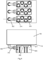
- figure 1 shows a part of a medium voltage switchgear in the form of a Gas insulated Switchgear (GIS) as an example.
- GIS Gas insulated Switchgear
- a circuit breaker CB compartment 100 is shown, along with a solid insulated cable connection box 200.
- the cable connection box 200 comprises a rear wall 201 facing towards a wall 110 of the CB compartment 100.
- the cable connection box 200 further comprises a centre axis 202.
- An electrical link 300 with a longitudinal axis 302 is located between the CB compartment 100 and the cable connection box 200.
- the lower part of the figure is a view from the side; the upper part is a bottom view.
- the cable connection boxes in these examples comprise busbar and sockets as internal conductors that are surrounded by an insulating material, for example epoxy, that is covered by a conductive, earthed layer, for example made from electric paint or from metal layer spraying.
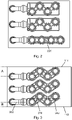
- Figure 2 shows for comparison the same GIS where one phase is equipped with a cable connection box 220 with four sockets in a line.
- the sockets have the same distance from each other. It is evident how the zig zag arrangement saves space in a first direction from the left to the right in figure 2 .
- This space can for example be used for the assembly of current transformers CTs or voltage transformers VTs.
- In a second direction, from the top to the bottom in figure 2 more space is required. This space is available anyway in most cases, as the required distance between the cable sockets is generally less than the space between the phases.
- Figure 3 shows an embodiment of a cable connection box 240 with a cente axis 242, where the individual sockets are staged in a way that space is available for the corresponding socket of the neighbouring phase. Due to the staging, the axes 242 and 302 are still parallel, but have an offset.Here, it can be advantageous to have an asymmetric arrangement of the phases, i.e. the distance from the lateral phases to the sidewalls of the compartment is different; A is not the same as B.
- FIG. 4 shows that the staging of the cable connections can be combined with symmetric phase distances when for example the electrical links 320 include a corresponding offset and the axes 322 are not parallel to the axes 242.
- Busbar 225 represents the case when the sockets are in a line, and the busbar 225 has a certain thickness and a certain cross-section for carrying the current.
- Feature 226 represents a connection to the electrical link 300 or 320, which is described in more detail with respect to figure 6 .
- busbar 205 is sufficient for the cable connection box 200.
- the general shape of 205 is the same as the shape of the busbar 225.
- Busbar 205 has to be wider than busbar 225 to connect the zig zag sockets. However, as the total cross-section does not have to be increased, busbar 205 can be thinner than busbar 225.
- Busbar 245 with a zig zag shape is provided. This shape is more complex regarding the manufacturing process, but it enables the space saving staging shown in the figures 3 and 4 .
- Busbar 245 can be bended from a profile; alternatively, it can nowadays be laser-cut from a sheet.
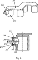
- FIG. 6 shows more detail on connection 226 referred to above, relating to how to connect a cable connection box with an electrical link.
- the leftmost socket 210 provides a screw-connection to the left.
- This screw connection comprises a tube-shaped extension 260 from the socket to the left side.
- the front surface 265 can be firmly connected for example to an electrical link 300 by tightening the screw 280 using a standard wrench from inside of the socket 210.
- the screw 280 rests on the locking ring 270.
- the locking ring provides a male left-hand thread 278 at its outer surface to match with the female left-hand thread 268.
- the locking ring 270 is screwed into the tube-shaped extension 260, using the feature 275 for turning the locking ring 270.
- the electrical link 300 is added at the left side and screw 280 is inserted and tightened. Due to the fact that the locking ring has a left-hand thread, it cannot become loose while screw 280 is tightened.
- the leftmost surface of the locking ring 270 does not protrude at the leftmost end of the tube-shaped extension 260, as the electrical contact between the tube shaped extension 260 and the electrical link 300 has to be established by the front surface 265.
- the mechanical contact has to be established by the surface 265 and the screw 280.
- the socket 210 with the extension 260 can for example be manufactured by founding.
- the busbar 255 and the further sockets can also be founded in the same step of production.
Claims (24)
- Appareil de connexion et compartiment de disjoncteur pour disjoncteur d'un appareillage de commutation moyenne tension, l'appareil de connexion comprenant :- une liaison électrique (300, 320) pour une phase de l'appareillage de commutation moyenne tension ; et- une boîte de connexion de câble (200, 240) pour la phase de l'appareillage de commutation moyenne tension ;la liaison électrique étant configurée pour se connecter au compartiment de disjoncteur (100) ;la boîte de connexion de câble étant configurée pour se connecter à la liaison électrique ;la boîte de connexion de câble comprenant trois ou plus de trois prises de connexion de câble (210) pour la phase de l'appareillage de commutation moyenne tension dans un agencement en zigzag ;la liaison électrique et la boîte de connexion de câble étant configurées de telle sorte que lorsque la liaison électrique est connectée au compartiment de disjoncteur et que la boîte de connexion de câble est connectée à la liaison électrique, une paroi arrière (201, 241) de la boîte de connexion de câble fait face à une paroi (110) du compartiment de disjoncteur et les trois ou plus de trois prises de connexion de câble étant orientées à l'opposé de la paroi du compartiment de disjoncteur ; etune prise de connexion de câble des trois ou plus de trois prises de connexion de câble (210) qui est adjacente à la liaison électrique (300, 320) lorsque la boîte de connexion de câble (200, 240) est connectée à la liaison électrique ayant un trou latéral, et la boîte de connexion de câble étant configurée pour être connectée à la liaison électrique par l'intermédiaire d'une vis (280) s'étendant à travers le trou latéral.
- Appareil de connexion et compartiment de disjoncteur selon la revendication 1, la liaison électrique (300, 320) étant configurée de telle sorte que lorsque la liaison électrique est connectée au compartiment de disjoncteur (100), une section de la liaison électrique a un axe longitudinal qui se trouve dans un plan parallèle à la paroi du compartiment de disjoncteur.
- Appareil de connexion et compartiment de disjoncteur selon l'une quelconque des revendications 1 à 2, la boîte de connexion de câble (200, 240) ayant un axe central parallèle à la paroi arrière de la boîte de connexion de câble, et les centres des prises de connexion de câble consécutives (210) se trouvant de part et d'autre de l'axe central de la boîte de connexion de câble.
- Appareil de connexion et compartiment de disjoncteur selon la revendication 3 lorsqu'elle dépend de la revendication 2, la liaison électrique (300) et la boîte de connexion de câble (200, 240) étant configurées de telle sorte que lorsque la liaison électrique est connectée au compartiment de disjoncteur et que la boîte de connexion de câble est connectée à la liaison électrique, l'axe longitudinal de la liaison électrique est parallèle à l'axe central de la boîte de connexion de câble.
- Appareil de connexion et compartiment de disjoncteur selon la revendication 4, l'axe central de la boîte de connexion de câble (240) se trouvant dans le plan parallèle à la paroi du compartiment de disjoncteur décalé d'un côté de l'axe longitudinal de la liaison électrique (300).
- Appareil de connexion et compartiment de disjoncteur selon la revendication 4, l'axe longitudinal de la liaison électrique (300) et l'axe central de la boîte de connexion de câbles (240) partageant le même axe.
- Appareil de connexion et compartiment de disjoncteur selon la revendication 3 lorsqu'elle dépend de la revendication 2, la liaison électrique (320) et la boîte de connexion de câble (200, 240) étant configurées de telle sorte que lorsque la liaison électrique est connectée au compartiment de disjoncteur et que la boîte de connexion de câble est connectée à la liaison électrique, l'axe longitudinal de la liaison électrique fait un angle avec l'axe central de la boîte de connexion de câble.
- Appareil de connexion et compartiment de disjoncteur selon l'une quelconque des revendications 3 à 7, la boîte de connexion de câble comprenant une barre omnibus (205) connectée aux trois ou plus de trois prises de connexion de câble (210), et deux côtés de la barre omnibus étant parallèles à l'axe central de la boîte de connexion de câble (200, 240).
- Appareil de connexion et compartiment de disjoncteur selon l'une quelconque des revendications 3 à 7, la boîte de connexion de câble comprenant une barre omnibus (245) connectée aux trois ou plus de trois prises de connexion de câble (210), et deux côtés de la barre omnibus étant sensiblement parallèles l'un à l'autre et suivant l'agencement en zigzag des prises de connexion de câble.
- Appareil de connexion et compartiment de disjoncteur selon la revendication 1, le trou latéral étant formé à partir d'une bague de verrouillage (270) avec un filetage mâle gauche (278) sur sa surface extérieure qui correspond à un filetage femelle gauche (268) de l'extension en forme de tube (260) de la prise de connexion de câble (210).
- Appareil de connexion et compartiment de disjoncteur selon l'une quelconque des revendications 1 à 10, la boîte de connexion de câble comprenant quatre ou plus de quatre prises de connexion de câble (210) dans un agencement en zigzag.
- Appareil disjoncteur pour un appareillage de commutation moyenne tension, l'appareil disjoncteur comprenant :- un compartiment de disjoncteur (100) ;- trois liaisons électriques (300, 320), chacune pour différentes phases de l'appareillage de commutation moyenne tension ; et- trois boîtes de connexion de câbles (200, 240), chacune pour les différentes phases de l'appareillage de commutation moyenne tension ;chaque liaison électrique étant connectée au compartiment de disjoncteur (100) ;chaque boîte de connexion de câble étant connectée à une liaison électrique respective ;chaque boîte de connexion de câble comprenant trois ou plus de trois prises de connexion de câble (210), chacune pour les différentes phases de l'appareillage de commutation moyenne tension dans un agencement en zigzag ;une paroi arrière de chaque boîte de connexion de câble faisant face à une paroi du compartiment de disjoncteur et les trois ou plus de trois prises de connexion de câble de chaque boîte de connexion de câble étant orientées à l'opposé de la paroi du compartiment de disjoncteur ; etune prise de connexion de câble des trois ou plus de trois prises de connexion de câble (210) qui est adjacente à la liaison électrique (300, 320) lorsque la boîte de connexion de câble (200, 240) est connectée à la liaison électrique ayant un trou latéral, et la boîte de connexion de câble étant configurée pour être connectée à la liaison électrique par l'intermédiaire d'une vis (280) s'étendant à travers le trou latéral.
- Appareil disjoncteur selon la revendication 12, une section de chaque liaison électrique ayant un axe longitudinal qui se trouve dans un plan parallèle à la paroi du compartiment de disjoncteur, et les axes longitudinaux des trois liaisons électriques étant parallèles les uns aux autres.
- Appareil disjoncteur selon l'une quelconque des revendications 12 à 13, chaque boîte de connexion de câble (200, 240) ayant un axe central parallèle à la paroi de la boîte de connexion de câble, et des centres des prises de connexion de câble consécutives (210) se trouvant de part et d'autre de l'axe central de la boîte de connexion de câble, et les axes centraux des trois boîtes de connexion de câble étant parallèles les uns aux autres.
- Appareil disjoncteur selon la revendication 14 lorsqu'elle dépend de la revendication 13, l'axe longitudinal de chaque liaison électrique étant parallèle à l'axe central de la boîte de connexion de câble auquel il est connecté.
- Appareil disjoncteur selon la revendication 15, l'axe central de chaque boîte de connexion de câble (240) se trouvant dans le plan parallèle à la paroi du compartiment de disjoncteur, et l'axe longitudinal de chaque liaison électrique (300) étant décalé d'un même côté de l'axe central de chaque boîte de connexion de câble à laquelle il est attaché.
- Appareil disjoncteur selon la revendication 16, la paroi du compartiment de disjoncteur ayant un premier bord parallèle à un second bord, et les axes longitudinaux des trois liaisons électriques étant parallèles au premier bord et au second bord.
- Appareil disjoncteur selon la revendication 17, une distance entre le premier bord et l'axe longitudinal d'une liaison électrique (300) adjacente au premier bord étant supérieure à une distance entre le second bord et l'axe longitudinal d'une liaison électrique (300) adjacente au second bord.
- Appareil disjoncteur selon la revendication 15, l'axe longitudinal de chaque liaison électrique (300) et l'axe central de la boîte de connexion de câble correspondant (240) auquel la liaison électrique est connectée partageant le même axe.
- Appareil disjoncteur selon la revendication 14 lorsqu'elle dépend de la revendication 13, l'axe longitudinal de chaque liaison électrique (320) faisant un angle avec l'axe central de la boîte de connexion de câble (200, 240) auquel il est connecté.
- Appareil disjoncteur selon la revendication 20, l'axe central de chaque boîte de connexion de câble (200, 240) se trouvant dans le plan parallèle à la paroi du compartiment de disjoncteur, et l'axe longitudinal de chaque liaison électrique (320) étant à un angle dans la même direction que l'axe central de chaque boîte de connexion de câble à laquelle il est attaché.
- Appareil disjoncteur selon la revendication 21, la paroi du compartiment de disjoncteur ayant un premier bord parallèle à un second bord, et les axes centraux des trois boîtes de connexion de câble étant parallèles au premier bord et au second bord.
- Appareil disjoncteur selon la revendication 22, une distance entre le premier bord et l'axe central d'une boîte de connexion de câble (200, 240) adjacente au premier bord étant égale à une distance entre le second bord et l'axe central d'une boîte de connexion de câble (200, 240) adjacente au second bord.
- Appareil disjoncteur selon l'une quelconque des revendications 12 à 23, chacune des boîtes de connexion de câble comprenant quatre ou plus de quatre prises de connexion de câble (210) dans un agencement en zigzag.
Priority Applications (1)
| Application Number | Priority Date | Filing Date | Title |
|---|---|---|---|
| EP18215584.6A EP3671995B1 (fr) | 2018-12-21 | 2018-12-21 | Appareil de connexion pour un disjoncteur d'un appareillage de commutation moyenne tension |
Applications Claiming Priority (1)
| Application Number | Priority Date | Filing Date | Title |
|---|---|---|---|
| EP18215584.6A EP3671995B1 (fr) | 2018-12-21 | 2018-12-21 | Appareil de connexion pour un disjoncteur d'un appareillage de commutation moyenne tension |
Publications (2)
| Publication Number | Publication Date |
|---|---|
| EP3671995A1 EP3671995A1 (fr) | 2020-06-24 |
| EP3671995B1 true EP3671995B1 (fr) | 2022-05-11 |
Family
ID=64959161
Family Applications (1)
| Application Number | Title | Priority Date | Filing Date |
|---|---|---|---|
| EP18215584.6A Active EP3671995B1 (fr) | 2018-12-21 | 2018-12-21 | Appareil de connexion pour un disjoncteur d'un appareillage de commutation moyenne tension |
Country Status (1)
| Country | Link |
|---|---|
| EP (1) | EP3671995B1 (fr) |
Family Cites Families (4)
| Publication number | Priority date | Publication date | Assignee | Title |
|---|---|---|---|---|
| JP3409484B2 (ja) * | 1994-12-27 | 2003-05-26 | 日新電機株式会社 | ガス絶縁開閉装置 |
| DE19809839A1 (de) * | 1998-03-02 | 1999-09-09 | Siemens Ag | Metallgekapselte, gasisolierte Schaltanlage mit gasgefüllten Behältern |
| DE19852410A1 (de) * | 1998-11-13 | 2000-05-18 | Abb Patent Gmbh | Gekapselte Mittelspannungsschaltanlage |
| US6242708B1 (en) * | 2000-01-03 | 2001-06-05 | Eaton Corporation | Isolator switch |
-
2018
- 2018-12-21 EP EP18215584.6A patent/EP3671995B1/fr active Active
Also Published As
| Publication number | Publication date |
|---|---|
| EP3671995A1 (fr) | 2020-06-24 |
Similar Documents
| Publication | Publication Date | Title |
|---|---|---|
| CN1038373C (zh) | 金属外壳内充高压气体的多相高压开关装置 | |
| US8481881B2 (en) | Electric circuit breaker and switchgear panel with circuit breaker | |
| KR100905020B1 (ko) | 스위치기어의 모선연결장치 및 그의 모선연결방법 | |
| EP1107408B1 (fr) | Installation de commutation à isolation gazeuse | |
| US4745522A (en) | Gas-insulated switchgear apparatus | |
| KR100374240B1 (ko) | 스위치 기어 및 특정 높이 금속 폐쇄형 스위치 기어 | |
| JP2007097332A (ja) | ガス絶縁スイッチギヤ | |
| US11901709B2 (en) | Gas-insulated switchgear | |
| US10164412B1 (en) | Switchgear with a two-high circuit interrupter configuration | |
| EP0459593B1 (fr) | Module à compartiments pour un système de distribution moyenne tension modulaire à enceinte métallique, et système de distribution assemblé avec ces modules | |
| EP1496585B1 (fr) | Armoire de distribution metallique fermee | |
| US6016247A (en) | Electricity distribution substation | |
| EP3671995B1 (fr) | Appareil de connexion pour un disjoncteur d'un appareillage de commutation moyenne tension | |
| CN101617450B (zh) | 高压开关设备 | |
| KR950003867B1 (ko) | 금속함체형 스위치기어 | |
| US20130201607A1 (en) | Pressurised gas-insulated multi-phase control panel | |
| JPH08340610A (ja) | ガス絶縁開閉装置 | |
| KR20110084833A (ko) | 가스로 절연된 고전압 측정 유닛 | |
| KR20180044563A (ko) | 가스절연개폐장치 연결 유닛 | |
| JPH0746726A (ja) | 金属閉鎖形スイッチギヤ | |
| KR100928933B1 (ko) | 고체 절연 부하개폐기 및 고체 절연 부하개폐기용전압변성기 접속장치 | |
| EP3671972B1 (fr) | Appareil de connexion pour un compartiment d'appareillage de commutation moyenne tension | |
| JPH01303002A (ja) | 受電用ガス絶縁開閉装置 | |
| JPH0226162Y2 (fr) | ||
| CN112602242B (zh) | 多相开关设备 |
Legal Events
| Date | Code | Title | Description |
|---|---|---|---|
| PUAI | Public reference made under article 153(3) epc to a published international application that has entered the european phase |
Free format text: ORIGINAL CODE: 0009012 |
|
| STAA | Information on the status of an ep patent application or granted ep patent |
Free format text: STATUS: THE APPLICATION HAS BEEN PUBLISHED |
|
| AK | Designated contracting states |
Kind code of ref document: A1 Designated state(s): AL AT BE BG CH CY CZ DE DK EE ES FI FR GB GR HR HU IE IS IT LI LT LU LV MC MK MT NL NO PL PT RO RS SE SI SK SM TR |
|
| AX | Request for extension of the european patent |
Extension state: BA ME |
|
| STAA | Information on the status of an ep patent application or granted ep patent |
Free format text: STATUS: REQUEST FOR EXAMINATION WAS MADE |
|
| 17P | Request for examination filed |
Effective date: 20201215 |
|
| RBV | Designated contracting states (corrected) |
Designated state(s): AL AT BE BG CH CY CZ DE DK EE ES FI FR GB GR HR HU IE IS IT LI LT LU LV MC MK MT NL NO PL PT RO RS SE SI SK SM TR |
|
| GRAP | Despatch of communication of intention to grant a patent |
Free format text: ORIGINAL CODE: EPIDOSNIGR1 |
|
| STAA | Information on the status of an ep patent application or granted ep patent |
Free format text: STATUS: GRANT OF PATENT IS INTENDED |
|
| INTG | Intention to grant announced |
Effective date: 20211214 |
|
| GRAS | Grant fee paid |
Free format text: ORIGINAL CODE: EPIDOSNIGR3 |
|
| GRAA | (expected) grant |
Free format text: ORIGINAL CODE: 0009210 |
|
| STAA | Information on the status of an ep patent application or granted ep patent |
Free format text: STATUS: THE PATENT HAS BEEN GRANTED |
|
| AK | Designated contracting states |
Kind code of ref document: B1 Designated state(s): AL AT BE BG CH CY CZ DE DK EE ES FI FR GB GR HR HU IE IS IT LI LT LU LV MC MK MT NL NO PL PT RO RS SE SI SK SM TR |
|
| RAP3 | Party data changed (applicant data changed or rights of an application transferred) |
Owner name: ABB SCHWEIZ AG |
|
| REG | Reference to a national code |
Ref country code: GB Ref legal event code: FG4D |
|
| REG | Reference to a national code |
Ref country code: CH Ref legal event code: EP |
|
| REG | Reference to a national code |
Ref country code: AT Ref legal event code: REF Ref document number: 1492280 Country of ref document: AT Kind code of ref document: T Effective date: 20220515 |
|
| REG | Reference to a national code |
Ref country code: DE Ref legal event code: R096 Ref document number: 602018035358 Country of ref document: DE |
|
| REG | Reference to a national code |
Ref country code: IE Ref legal event code: FG4D |
|
| REG | Reference to a national code |
Ref country code: LT Ref legal event code: MG9D |
|
| REG | Reference to a national code |
Ref country code: NL Ref legal event code: MP Effective date: 20220511 |
|
| REG | Reference to a national code |
Ref country code: AT Ref legal event code: MK05 Ref document number: 1492280 Country of ref document: AT Kind code of ref document: T Effective date: 20220511 |
|
| PG25 | Lapsed in a contracting state [announced via postgrant information from national office to epo] |
Ref country code: SE Free format text: LAPSE BECAUSE OF FAILURE TO SUBMIT A TRANSLATION OF THE DESCRIPTION OR TO PAY THE FEE WITHIN THE PRESCRIBED TIME-LIMIT Effective date: 20220511 Ref country code: PT Free format text: LAPSE BECAUSE OF FAILURE TO SUBMIT A TRANSLATION OF THE DESCRIPTION OR TO PAY THE FEE WITHIN THE PRESCRIBED TIME-LIMIT Effective date: 20220912 Ref country code: NO Free format text: LAPSE BECAUSE OF FAILURE TO SUBMIT A TRANSLATION OF THE DESCRIPTION OR TO PAY THE FEE WITHIN THE PRESCRIBED TIME-LIMIT Effective date: 20220811 Ref country code: NL Free format text: LAPSE BECAUSE OF FAILURE TO SUBMIT A TRANSLATION OF THE DESCRIPTION OR TO PAY THE FEE WITHIN THE PRESCRIBED TIME-LIMIT Effective date: 20220511 Ref country code: LT Free format text: LAPSE BECAUSE OF FAILURE TO SUBMIT A TRANSLATION OF THE DESCRIPTION OR TO PAY THE FEE WITHIN THE PRESCRIBED TIME-LIMIT Effective date: 20220511 Ref country code: HR Free format text: LAPSE BECAUSE OF FAILURE TO SUBMIT A TRANSLATION OF THE DESCRIPTION OR TO PAY THE FEE WITHIN THE PRESCRIBED TIME-LIMIT Effective date: 20220511 Ref country code: GR Free format text: LAPSE BECAUSE OF FAILURE TO SUBMIT A TRANSLATION OF THE DESCRIPTION OR TO PAY THE FEE WITHIN THE PRESCRIBED TIME-LIMIT Effective date: 20220812 Ref country code: FI Free format text: LAPSE BECAUSE OF FAILURE TO SUBMIT A TRANSLATION OF THE DESCRIPTION OR TO PAY THE FEE WITHIN THE PRESCRIBED TIME-LIMIT Effective date: 20220511 Ref country code: ES Free format text: LAPSE BECAUSE OF FAILURE TO SUBMIT A TRANSLATION OF THE DESCRIPTION OR TO PAY THE FEE WITHIN THE PRESCRIBED TIME-LIMIT Effective date: 20220511 Ref country code: BG Free format text: LAPSE BECAUSE OF FAILURE TO SUBMIT A TRANSLATION OF THE DESCRIPTION OR TO PAY THE FEE WITHIN THE PRESCRIBED TIME-LIMIT Effective date: 20220811 Ref country code: AT Free format text: LAPSE BECAUSE OF FAILURE TO SUBMIT A TRANSLATION OF THE DESCRIPTION OR TO PAY THE FEE WITHIN THE PRESCRIBED TIME-LIMIT Effective date: 20220511 |
|
| PG25 | Lapsed in a contracting state [announced via postgrant information from national office to epo] |
Ref country code: RS Free format text: LAPSE BECAUSE OF FAILURE TO SUBMIT A TRANSLATION OF THE DESCRIPTION OR TO PAY THE FEE WITHIN THE PRESCRIBED TIME-LIMIT Effective date: 20220511 Ref country code: PL Free format text: LAPSE BECAUSE OF FAILURE TO SUBMIT A TRANSLATION OF THE DESCRIPTION OR TO PAY THE FEE WITHIN THE PRESCRIBED TIME-LIMIT Effective date: 20220511 Ref country code: LV Free format text: LAPSE BECAUSE OF FAILURE TO SUBMIT A TRANSLATION OF THE DESCRIPTION OR TO PAY THE FEE WITHIN THE PRESCRIBED TIME-LIMIT Effective date: 20220511 Ref country code: IS Free format text: LAPSE BECAUSE OF FAILURE TO SUBMIT A TRANSLATION OF THE DESCRIPTION OR TO PAY THE FEE WITHIN THE PRESCRIBED TIME-LIMIT Effective date: 20220911 |
|
| PG25 | Lapsed in a contracting state [announced via postgrant information from national office to epo] |
Ref country code: SM Free format text: LAPSE BECAUSE OF FAILURE TO SUBMIT A TRANSLATION OF THE DESCRIPTION OR TO PAY THE FEE WITHIN THE PRESCRIBED TIME-LIMIT Effective date: 20220511 Ref country code: SK Free format text: LAPSE BECAUSE OF FAILURE TO SUBMIT A TRANSLATION OF THE DESCRIPTION OR TO PAY THE FEE WITHIN THE PRESCRIBED TIME-LIMIT Effective date: 20220511 Ref country code: RO Free format text: LAPSE BECAUSE OF FAILURE TO SUBMIT A TRANSLATION OF THE DESCRIPTION OR TO PAY THE FEE WITHIN THE PRESCRIBED TIME-LIMIT Effective date: 20220511 Ref country code: EE Free format text: LAPSE BECAUSE OF FAILURE TO SUBMIT A TRANSLATION OF THE DESCRIPTION OR TO PAY THE FEE WITHIN THE PRESCRIBED TIME-LIMIT Effective date: 20220511 Ref country code: DK Free format text: LAPSE BECAUSE OF FAILURE TO SUBMIT A TRANSLATION OF THE DESCRIPTION OR TO PAY THE FEE WITHIN THE PRESCRIBED TIME-LIMIT Effective date: 20220511 Ref country code: CZ Free format text: LAPSE BECAUSE OF FAILURE TO SUBMIT A TRANSLATION OF THE DESCRIPTION OR TO PAY THE FEE WITHIN THE PRESCRIBED TIME-LIMIT Effective date: 20220511 |
|
| REG | Reference to a national code |
Ref country code: DE Ref legal event code: R097 Ref document number: 602018035358 Country of ref document: DE |
|
| PLBE | No opposition filed within time limit |
Free format text: ORIGINAL CODE: 0009261 |
|
| STAA | Information on the status of an ep patent application or granted ep patent |
Free format text: STATUS: NO OPPOSITION FILED WITHIN TIME LIMIT |
|
| PG25 | Lapsed in a contracting state [announced via postgrant information from national office to epo] |
Ref country code: AL Free format text: LAPSE BECAUSE OF FAILURE TO SUBMIT A TRANSLATION OF THE DESCRIPTION OR TO PAY THE FEE WITHIN THE PRESCRIBED TIME-LIMIT Effective date: 20220511 |
|
| 26N | No opposition filed |
Effective date: 20230214 |
|
| PG25 | Lapsed in a contracting state [announced via postgrant information from national office to epo] |
Ref country code: SI Free format text: LAPSE BECAUSE OF FAILURE TO SUBMIT A TRANSLATION OF THE DESCRIPTION OR TO PAY THE FEE WITHIN THE PRESCRIBED TIME-LIMIT Effective date: 20220511 |
|
| REG | Reference to a national code |
Ref country code: CH Ref legal event code: PL |
|
| GBPC | Gb: european patent ceased through non-payment of renewal fee |
Effective date: 20221221 |
|
| REG | Reference to a national code |
Ref country code: BE Ref legal event code: MM Effective date: 20221231 |
|
| PG25 | Lapsed in a contracting state [announced via postgrant information from national office to epo] |
Ref country code: LU Free format text: LAPSE BECAUSE OF NON-PAYMENT OF DUE FEES Effective date: 20221221 |
|
| PG25 | Lapsed in a contracting state [announced via postgrant information from national office to epo] |
Ref country code: LI Free format text: LAPSE BECAUSE OF NON-PAYMENT OF DUE FEES Effective date: 20221231 Ref country code: IE Free format text: LAPSE BECAUSE OF NON-PAYMENT OF DUE FEES Effective date: 20221221 Ref country code: GB Free format text: LAPSE BECAUSE OF NON-PAYMENT OF DUE FEES Effective date: 20221221 Ref country code: CH Free format text: LAPSE BECAUSE OF NON-PAYMENT OF DUE FEES Effective date: 20221231 |
|
| PG25 | Lapsed in a contracting state [announced via postgrant information from national office to epo] |
Ref country code: BE Free format text: LAPSE BECAUSE OF NON-PAYMENT OF DUE FEES Effective date: 20221231 |
|
| PG25 | Lapsed in a contracting state [announced via postgrant information from national office to epo] |
Ref country code: IT Free format text: LAPSE BECAUSE OF FAILURE TO SUBMIT A TRANSLATION OF THE DESCRIPTION OR TO PAY THE FEE WITHIN THE PRESCRIBED TIME-LIMIT Effective date: 20220511 |
|
| PGFP | Annual fee paid to national office [announced via postgrant information from national office to epo] |
Ref country code: FR Payment date: 20231222 Year of fee payment: 6 Ref country code: DE Payment date: 20231214 Year of fee payment: 6 |
|
| PG25 | Lapsed in a contracting state [announced via postgrant information from national office to epo] |
Ref country code: HU Free format text: LAPSE BECAUSE OF FAILURE TO SUBMIT A TRANSLATION OF THE DESCRIPTION OR TO PAY THE FEE WITHIN THE PRESCRIBED TIME-LIMIT; INVALID AB INITIO Effective date: 20181221 |
|
| PG25 | Lapsed in a contracting state [announced via postgrant information from national office to epo] |
Ref country code: CY Free format text: LAPSE BECAUSE OF FAILURE TO SUBMIT A TRANSLATION OF THE DESCRIPTION OR TO PAY THE FEE WITHIN THE PRESCRIBED TIME-LIMIT Effective date: 20220511 |