EP3671081A2 - Kühlschrank - Google Patents
Kühlschrank Download PDFInfo
- Publication number
- EP3671081A2 EP3671081A2 EP19213114.2A EP19213114A EP3671081A2 EP 3671081 A2 EP3671081 A2 EP 3671081A2 EP 19213114 A EP19213114 A EP 19213114A EP 3671081 A2 EP3671081 A2 EP 3671081A2
- Authority
- EP
- European Patent Office
- Prior art keywords
- roller
- storage component
- rail
- transverse
- storage
- Prior art date
- Legal status (The legal status is an assumption and is not a legal conclusion. Google has not performed a legal analysis and makes no representation as to the accuracy of the status listed.)
- Withdrawn
Links
Images


Classifications
-
- F—MECHANICAL ENGINEERING; LIGHTING; HEATING; WEAPONS; BLASTING
- F25—REFRIGERATION OR COOLING; COMBINED HEATING AND REFRIGERATION SYSTEMS; HEAT PUMP SYSTEMS; MANUFACTURE OR STORAGE OF ICE; LIQUEFACTION SOLIDIFICATION OF GASES
- F25D—REFRIGERATORS; COLD ROOMS; ICE-BOXES; COOLING OR FREEZING APPARATUS NOT OTHERWISE PROVIDED FOR
- F25D25/00—Charging, supporting, and discharging the articles to be cooled
- F25D25/02—Charging, supporting, and discharging the articles to be cooled by shelves
- F25D25/024—Slidable shelves
- F25D25/025—Drawers
-
- F—MECHANICAL ENGINEERING; LIGHTING; HEATING; WEAPONS; BLASTING
- F25—REFRIGERATION OR COOLING; COMBINED HEATING AND REFRIGERATION SYSTEMS; HEAT PUMP SYSTEMS; MANUFACTURE OR STORAGE OF ICE; LIQUEFACTION SOLIDIFICATION OF GASES
- F25D—REFRIGERATORS; COLD ROOMS; ICE-BOXES; COOLING OR FREEZING APPARATUS NOT OTHERWISE PROVIDED FOR
- F25D11/00—Self-contained movable devices, e.g. domestic refrigerators
-
- F—MECHANICAL ENGINEERING; LIGHTING; HEATING; WEAPONS; BLASTING
- F25—REFRIGERATION OR COOLING; COMBINED HEATING AND REFRIGERATION SYSTEMS; HEAT PUMP SYSTEMS; MANUFACTURE OR STORAGE OF ICE; LIQUEFACTION SOLIDIFICATION OF GASES
- F25D—REFRIGERATORS; COLD ROOMS; ICE-BOXES; COOLING OR FREEZING APPARATUS NOT OTHERWISE PROVIDED FOR
- F25D25/00—Charging, supporting, and discharging the articles to be cooled
- F25D25/02—Charging, supporting, and discharging the articles to be cooled by shelves
- F25D25/024—Slidable shelves
Definitions
- Embodiments of the invention relate to a refrigerator.
- CN1105280C discloses a refrigerator tray assembly that can be inserted into and extracted from a refrigerating chamber.
- the tray assembly has a tray that can be slidably mounted on a guiding component on two side walls of the refrigerating chamber, a vertical roller mounted on two ends of the tray and in contact with the guiding component, and a transverse roller mounted on two sides of the tray and in contact with a side wall of the refrigerating chamber.
- the tray assembly enables the tray to be inserted into and extracted from the refrigerating chamber quite conveniently. Therefore, shaking in a left-right direction generated when the tray is inserted and extracted is avoided.
- An objective of embodiments of the invention is to provide a refrigerator having a storage component with improved sliding performance.
- An aspect of the embodiments of the invention relates to a refrigerator.
- the refrigerator includes: a storage chamber, having a front opening and a posterior chamber wall facing the front opening; a rail located in the storage chamber; a storage component, suitable for moving, along the rail and in a front-back direction, between a first extreme position and a second extreme position, where the storage component is closest to the posterior chamber wall when the storage component is in the first extreme position; a first roller and a second roller that are at least partially located between the storage component and the rail in a vertical direction, where the storage component is suitable for being supported on the rail by the first roller and the second roller, and the second roller is in front of the first roller at least when the storage component is in the first extreme position; and a transverse roller at least partially located between the storage component and the rail in a horizontal direction to prevent the storage component from moving in a transverse direction of the storage chamber, where when the storage component is in the first extreme position, the transverse roller is located between the first roller and the second roller in the front-back direction.
- the storage component is supported by the first roller and the second roller that are spaced apart in the front-back direction, and prevents, by using the transverse roller, the storage component from shaking in the transverse direction of the storage chamber, thereby making front-back movement of the storage component more smooth and more stable.
- the transverse roller being located between the first roller and the second roller makes it possible to prevent, by using the transverse roller, the storage component from shaking in the transverse direction throughout entire movement.
- the transverse roller is fixed on the rail and the transverse roller is in proximity to the second roller at least when the storage component is in the first extreme position.
- the refrigerator includes an anti-overturn portion located between the rail and the storage component. After the storage component moves forward by a predetermined journey, the anti-overturn portion is in contact with the transverse roller to prevent the storage component from overturning downward.
- the transverse roller is fixed in the front of the rail, and the anti-overturn portion is located in the rear of the storage component.
- the anti-overturn portion is formed by the second roller.
- the anti-overturn portion includes a fourth roller.
- the fourth roller is fixed in the rear of the storage component and is at least partially located between the rail and the storage component. After the storage component moves forward by the predetermined journey, the fourth roller is in contact with the transverse roller to prevent the storage component from overturning downward.
- a projection of the transverse roller in the front-back direction and a projection of the first roller in the front-back direction at least partially overlap. After the storage component moves forward by a predetermined journey, the transverse roller is in contact with the first roller to prevent the storage component from overturning downward.
- the second roller and the transverse roller are fixed in the front of the rail, and the first roller is located in the rear of the storage component.
- the transverse roller is located above the second roller in the vertical direction.
- the rail includes a bottom rail and a side rail coupled to one side of the bottom rail and extending upward.
- the transverse roller is fixed on the side rail.
- the second roller is fixed on the bottom rail.
- the rail includes a bottom rail.
- the first roller is fixed in the rear of the storage component and suitable for moving along the bottom rail.
- the front of the bottom rail has a protruding portion.
- the transverse roller is located in front of the protruding portion.
- the transverse roller is located between the protruding portion and the second roller.
- the transverse roller is located above the protruding portion and the second roller.
- a refrigerator including: a storage chamber having a front opening; a rail; a storage component suitable for sliding along the rail in a front-back direction; a transverse roller at least partially located between the storage component and the rail in a horizontal direction, where the transverse roller is fixed in the front of the rail and suitable for being in contact with a side wall of the storage component; and an anti-overturn portion fixed in the rear of the storage component, where the anti-overturn portion is suitable for being in contact with the transverse roller.
- the refrigerator includes a first roller disposed in the rear of the storage component.
- the anti-overturn portion is formed by the first roller.
- the first roller is used to support the storage component in a vertical direction and slide along the rail.
- the refrigerator includes a first roller and a second roller that are located between the storage component and the rail in a vertical direction.
- the storage component is suitable for being supported on the rail by the first roller and the second roller.
- the transverse roller is located between the first roller and the second roller in the front-back direction.
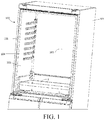
- a refrigerator 100 includes a heat insulation case body 101.
- the case body 101 has a storage chamber 102 and the storage chamber 102 has a front opening 104.
- the storage chamber 102 may be closed with one door or a pair of doors (not shown in the figure).
- the storage chamber 102 has a pair of rails 1.
- the rail 1 is fixed on a corresponding side chamber wall 103 of the storage chamber 102 by using a fixing apparatus (not shown in the figure).
- a fixing apparatus not shown in the figure.
- the refrigerator 100 includes a storage component 2. Two sides of the storage component 2 can respectively slide along corresponding rails 1 and move in a front-back direction. The storage component 2 can move forward towards the front opening 104 of the storage chamber 102 so that at least a part of the storage component 2 is pulled out of the storage chamber 102.
- the storage component 2 can move between a first extreme position and a second extreme position.
- a distance between the storage component 2 and the posterior chamber wall 105 of the storage chamber 102 facing the front opening 104 is smallest when the storage component 2 is in the first extreme position.
- a distance between the storage component 2 and the posterior chamber wall 105 is largest when the storage component 2 is in the second extreme position.
- the storage component 2 is in the first extreme position relative to the rail 1.
- the storage component 2 is in the second extreme position relative to the rail 1.
- the storage component 2 moves in a front-back direction independent of a door used to close the storage chamber 102. It is easy to understand that in some alternative embodiments, the storage component 2 may also move with the movement of the door.
- the storage component 2 may include a container, for example, an upward opening drawer or tray. In some other embodiments, the storage component 2 may also include a shelf roughly shaped as a plate.
- a first roller 3 and a second roller 4 are between the storage component 2 and the rail 1.
- the storage component 2 is supported on the rail 1 by the first roller 3 and the second roller 4.
- the first roller 3 and the second roller 4 each include a wheel body rolling about a horizontally extending axis.
- the first roller 3 and the second roller 4 roll while bearing the weight of the storage component 2.
- the first roller 3 and the second roller 4 are at least partially located between the storage component 2 and the rail 1 in the vertical direction.
- the first roller 3 and the second roller 4 are spaced apart in the front-back direction, and the second roller 4 is located in front of the first roller 3.
- the second roller 4 may be in proximity to the front opening of the storage chamber 102.
- the first roller 3 may be located in the rear of the storage chamber 102.
- At least one of the first roller 3 and the second roller 4 is fixed on the rail 1 to support the storage component 2.
- a roller fixed on the rail 1 is abutted against the storage component 2 and rolls.
- the second roller 4 is fixed in the front of the rail 1 and is closer to the front opening of the storage chamber 102.
- the second roller 4 slides along a corresponding part of the storage component 2 and supports the storage component 2.
- the first roller 3 may be fixed on the storage component 2, and the storage component 2 is supported on the rail 1 by the first roller 3. When the storage component 2 is in motion, the first roller 3 slides along the rail 1. By using the first roller 3 and the second roller 4, the storage component 2 is supported and can smoothly move along the rail 1.
- the first roller 3 may be fixed in the rear of the storage component 2. In the present embodiment, there is a gap between the first roller 3 and a posterior wall 21 of the storage component 2.
- the refrigerator 100 includes a transverse roller 5 located between the storage component 2 and the rail 1 in a transverse direction of the storage chamber 102, so that the storage component 2 is prevented from moving in a left-right direction in front-back movement. Therefore, shaking of the storage component 2 is reduced.
- the transverse roller 5 may have a wheel body rolling about a vertically extending axis.
- the transverse roller 5 is mounted on the rail 1 and is in contact with a side wall 22 of the storage component 2.
- the side wall 22 of the storage component 2 slides along the transverse roller 5. Therefore, the shaking of the storage component 2 in the transverse direction of the storage chamber 102 is reduced.
- the transverse roller 5 may also be mounted on the storage component 2 and suitable for being in contact with the rail 1 or the side chamber wall 103 so as to reduce the shaking of the storage component 2 in the left-right direction.
- An elastic body 51 may be sleeved on the transverse roller 5.
- the elastic body 51 is in contact with the side wall 22 of the storage component 2. This not only helps to reduce noise produced when the storage component 2 is in motion, but also helps to further reduce the shaking of the storage component 2.
- the transverse roller 5 fixed on the rail 1 is closer to the second roller 4 between the first roller 3 and the second roller 4. This helps to increase a journey length of the transverse roller 5 in contact with the storage component 2. It is understandable that in the alternative embodiment in which the transverse roller 5 is fixed on the storage component 2, the transverse roller 5 may be closer to the first roller 3.
- the transverse roller 5 when the storage component 2 is in the first extreme position, the transverse roller 5 may be located between the first roller 3 and the second roller 4 in the front-back direction. If the second roller 4 remains in contact with the storage component 2, the transverse roller 5 may also be in contact with the storage component 2.
- the transverse roller 5 is located between the first roller 3 and the second roller 4 in the front-back direction.
- the transverse roller 5 may be located above the second roller 4 in the vertical direction, so that the transverse roller 5 is prevented from reducing a pull-out distance of the storage component 2.
- the rail 1 may include a protruding portion 7 located in the front of the rail 1.
- the protruding portion 7 is located behind the second roller 4.
- the first roller 3 fixed in the rear of the storage component 2 is in contact with the protruding portion 7 when sliding to the front of the rail 1, thereby reminding a user that the storage component 2 is pulled out to a design limit and the storage component 2 does not need to be pulled out any more.
- the storage component 2 may include an anti-overturn portion 6 at least partially located in a gap between the rail 1 and the storage component 2.
- the anti-overturn portion 6 may protrude from the side wall 22 of the storage component 2. After the storage component 2 moves forward by a predetermined journey, the anti-overturn portion 6 is in contact with the transverse roller 5. This can prevent a front end of the storage component 2, which is filled with a heavy object and whose center of gravity is located outside the storage component 2, from excessively overturning downward and falling off from the refrigerator 100.
- the transverse roller 5 may be located between the protruding portion 7 and the second roller 4 in the front-back direction. Therefore, only after the storage component 2 overcomes hindrance of the protruding portion 7 and continues to move forward, for example, the storage component 2 moves forward and passes over the entire protruding portion 7 or passes over a part of the protruding portion, the anti-overturn portion 6 becomes in contact with the transverse roller 5 to prevent the storage component 2 from excessively overturning and falling off.
- the transverse roller 5 may be located above the protruding portion 7, which is more helpful in preventing the storage component 2 from excessively overturning downward. Projections of the anti-overturn portion 6 and the protruding portion 7 in the front-back direction may not overlap, and therefore the anti-overturn portion 6 may not be in contact with the protruding portion 7. After the storage component 2 overcomes the hindrance of the protruding portion 7 and continues to move forward, the anti-overturn portion 6 becomes in contact with the transverse roller 5 to prevent the storage component 2 from excessively overturning and falling off.
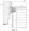
- the rail 1 may include a bottom rail 11 and a side rail 12 connected to the bottom rail 11 and extending upward.
- the second roller 4 is fixed on the bottom rail 11.
- the first roller 3 slides along the bottom rail 11.
- the transverse roller 5 may be fixed on the side rail 12.
- the anti-overturn portion 6 may be located between the side rail 12 and the side wall 22 of the storage component 2.
- the anti-overturn portion 6 may be disposed in proximity to the first roller 3. As shown in FIG. 3 , FIG. 4 , and FIG. 6 , the anti-overturn portion 6 may include a fourth roller 8 at least partially located between the side rail 12 and the side wall 22 in the left-right direction. Projections of the fourth roller 8 and the transverse roller 5 in the front-back direction at least partially overlap, so that after the storage component 2 moves forward by a predetermined journey, the fourth roller 8 is abutted against the transverse roller 5 to prevent the storage component 2 from overturning downward.
- the fourth roller 8 may be suspended and pass over the protruding portion 7.
- the fourth roller 8 may be coupled to the first roller 3.
- the fourth roller 8 and the first roller 3 may have a same central axis.
- the diameter of the fourth roller 8 is less than that of the first roller 3, so that the fourth roller 8 is suspended when the storage component 2 is in motion.
- An elastic sheath may be sleeved on the fourth roller 8.
- the anti-overturn portion may not be rotatably disposed on the side wall 22 of the storage component 2.
- the anti-overturn portion 6 may be integrally formed on the side wall 22 or separately assembled onto the storage component 2 (for example, the anti-overturn portion 6 is disposed on the second roller 4).
- FIG. 7 is a schematic sectional view of a storage unit according to another embodiment of the invention.
- a difference of the present embodiment from the foregoing embodiments is in that in addition to supporting the storage component 2, the first roller 43 extends in between the rail 1 and the storage component 2, and projections of the first roller 43 and the transverse roller 5 in the front-back direction at least partially overlap, so that after the storage component 2 is pulled out by the predetermined journey, the first roller 43 is abutted against the transverse roller 5 to prevent the storage component 2 from overturning downward.
- the anti-overturn portion 6 is formed by the first roller 43.
- Other components are disposed in the same way as those in the embodiments described above.
Landscapes
- Engineering & Computer Science (AREA)
- Chemical & Material Sciences (AREA)
- Combustion & Propulsion (AREA)
- Physics & Mathematics (AREA)
- Mechanical Engineering (AREA)
- Thermal Sciences (AREA)
- General Engineering & Computer Science (AREA)
- Refrigerator Housings (AREA)
Applications Claiming Priority (1)
| Application Number | Priority Date | Filing Date | Title |
|---|---|---|---|
| CN201811540539.0A CN111322805B (zh) | 2018-12-17 | 2018-12-17 | 冰箱 |
Publications (2)
| Publication Number | Publication Date |
|---|---|
| EP3671081A2 true EP3671081A2 (de) | 2020-06-24 |
| EP3671081A3 EP3671081A3 (de) | 2020-09-16 |
Family
ID=68766580
Family Applications (1)
| Application Number | Title | Priority Date | Filing Date |
|---|---|---|---|
| EP19213114.2A Withdrawn EP3671081A3 (de) | 2018-12-17 | 2019-12-03 | Kühlschrank |
Country Status (2)
| Country | Link |
|---|---|
| EP (1) | EP3671081A3 (de) |
| CN (1) | CN111322805B (de) |
Families Citing this family (2)
| Publication number | Priority date | Publication date | Assignee | Title |
|---|---|---|---|---|
| CN112197497B (zh) * | 2020-09-17 | 2025-01-14 | 广东凯得智能科技股份有限公司 | 一种可进行自动推出功能的冷藏装置 |
| CN112197496B (zh) * | 2020-09-17 | 2025-01-14 | 广东凯得智能科技股份有限公司 | 一种具有自动推出功能的冷藏装置 |
Citations (1)
| Publication number | Priority date | Publication date | Assignee | Title |
|---|---|---|---|---|
| CN1105280C (zh) | 1996-10-21 | 2003-04-09 | 大宇电子株式会社 | 冰箱托盘组件 |
Family Cites Families (14)
| Publication number | Priority date | Publication date | Assignee | Title |
|---|---|---|---|---|
| JPH02106686A (ja) * | 1988-10-13 | 1990-04-18 | Mitsubishi Electric Corp | 引出しケースの自動開閉装置 |
| DE4027468A1 (de) * | 1990-08-30 | 1992-03-05 | Willach Gmbh Geb | Schubladenfuehrung |
| JPH0534055A (ja) * | 1991-07-31 | 1993-02-09 | Toshiba Corp | 貯蔵庫 |
| JPH10300336A (ja) * | 1997-04-23 | 1998-11-13 | Matsushita Refrig Co Ltd | 冷蔵庫 |
| JP3648052B2 (ja) * | 1998-04-15 | 2005-05-18 | 三菱電機株式会社 | 冷蔵庫 |
| KR100802174B1 (ko) * | 2005-11-16 | 2008-02-12 | 엘지전자 주식회사 | 냉장고용 바스켓 출납구조 |
| KR101486347B1 (ko) * | 2008-04-15 | 2015-01-26 | 엘지전자 주식회사 | 냉장고 |
| US9033437B2 (en) * | 2013-03-15 | 2015-05-19 | Whirlpool Corporation | Slide assembly for refrigerator storage drawer |
| US20140265807A1 (en) * | 2013-03-15 | 2014-09-18 | Whirlpool Corporation | Apparatus, system, and method for storage in a refrigerated appliance |
| US9212848B2 (en) * | 2013-03-15 | 2015-12-15 | Whirlpool Corporation | Apparatus, system, and method for storage in a refrigerated appliance |
| CN103292560B (zh) * | 2013-05-10 | 2016-03-09 | 海信容声(广东)冰箱有限公司 | 一种冰箱抽屉推拉结构 |
| CN203586664U (zh) * | 2013-12-10 | 2014-05-07 | 广东奥马电器股份有限公司 | 装配滚轮的冰箱下横条结构 |
| KR102373219B1 (ko) * | 2015-12-10 | 2022-03-17 | 삼성전자주식회사 | 냉장고 |
| CN206641606U (zh) * | 2016-12-23 | 2017-11-17 | 杨怡雄 | 收纳柜 |
-
2018
- 2018-12-17 CN CN201811540539.0A patent/CN111322805B/zh active Active
-
2019
- 2019-12-03 EP EP19213114.2A patent/EP3671081A3/de not_active Withdrawn
Patent Citations (1)
| Publication number | Priority date | Publication date | Assignee | Title |
|---|---|---|---|---|
| CN1105280C (zh) | 1996-10-21 | 2003-04-09 | 大宇电子株式会社 | 冰箱托盘组件 |
Also Published As
| Publication number | Publication date |
|---|---|
| EP3671081A3 (de) | 2020-09-16 |
| CN111322805B (zh) | 2022-10-28 |
| CN111322805A (zh) | 2020-06-23 |
Similar Documents
| Publication | Publication Date | Title |
|---|---|---|
| KR101896466B1 (ko) | 냉장고 | |
| EP2175218B1 (de) | Kühlanlage | |
| EP2728284A2 (de) | Kühlschrank | |
| US20150230604A1 (en) | Drawer pull-out guide | |
| JP3419988B2 (ja) | 冷蔵庫 | |
| KR102440262B1 (ko) | 냉장고 | |
| EP3671081A2 (de) | Kühlschrank | |
| US20210321767A1 (en) | Sliding element guide system | |
| JP2017020718A (ja) | 冷蔵庫の引出装置 | |
| US10551113B1 (en) | Appliance equipped with a cascading basket system | |
| CN205425607U (zh) | 抽屉及具有该抽屉的冰箱 | |
| US2997356A (en) | Sliding shelf | |
| KR101965980B1 (ko) | 선반 장착용 슬라이딩 레일 | |
| CN107314591B (zh) | 抽屉组件及冰箱 | |
| JP5971524B2 (ja) | ウォールキャビネット | |
| KR20140000100A (ko) | 드로어를 구비한 냉장고 | |
| US2586138A (en) | Stove drawer track | |
| JP6985861B2 (ja) | 冷蔵庫 | |
| JP3212164U (ja) | 減音ガイドレール付引き戸型収納家具 | |
| JP6178100B2 (ja) | 冷蔵庫 | |
| KR101662942B1 (ko) | 냉장고 | |
| JP2009014266A (ja) | 冷蔵庫 | |
| JP2696023B2 (ja) | 貯蔵庫 | |
| JP2001091148A (ja) | 貯蔵庫における引出式扉の構造 | |
| EP3845845A1 (de) | Haushaltsgerät |
Legal Events
| Date | Code | Title | Description |
|---|---|---|---|
| PUAI | Public reference made under article 153(3) epc to a published international application that has entered the european phase |
Free format text: ORIGINAL CODE: 0009012 |
|
| STAA | Information on the status of an ep patent application or granted ep patent |
Free format text: STATUS: THE APPLICATION HAS BEEN PUBLISHED |
|
| AK | Designated contracting states |
Kind code of ref document: A2 Designated state(s): AL AT BE BG CH CY CZ DE DK EE ES FI FR GB GR HR HU IE IS IT LI LT LU LV MC MK MT NL NO PL PT RO RS SE SI SK SM TR |
|
| AX | Request for extension of the european patent |
Extension state: BA ME |
|
| PUAL | Search report despatched |
Free format text: ORIGINAL CODE: 0009013 |
|
| AK | Designated contracting states |
Kind code of ref document: A3 Designated state(s): AL AT BE BG CH CY CZ DE DK EE ES FI FR GB GR HR HU IE IS IT LI LT LU LV MC MK MT NL NO PL PT RO RS SE SI SK SM TR |
|
| AX | Request for extension of the european patent |
Extension state: BA ME |
|
| RIC1 | Information provided on ipc code assigned before grant |
Ipc: F25D 25/02 20060101AFI20200810BHEP |
|
| STAA | Information on the status of an ep patent application or granted ep patent |
Free format text: STATUS: REQUEST FOR EXAMINATION WAS MADE |
|
| 17P | Request for examination filed |
Effective date: 20210316 |
|
| RBV | Designated contracting states (corrected) |
Designated state(s): AL AT BE BG CH CY CZ DE DK EE ES FI FR GB GR HR HU IE IS IT LI LT LU LV MC MK MT NL NO PL PT RO RS SE SI SK SM TR |
|
| GRAP | Despatch of communication of intention to grant a patent |
Free format text: ORIGINAL CODE: EPIDOSNIGR1 |
|
| STAA | Information on the status of an ep patent application or granted ep patent |
Free format text: STATUS: GRANT OF PATENT IS INTENDED |
|
| INTG | Intention to grant announced |
Effective date: 20230522 |
|
| STAA | Information on the status of an ep patent application or granted ep patent |
Free format text: STATUS: THE APPLICATION IS DEEMED TO BE WITHDRAWN |
|
| 18D | Application deemed to be withdrawn |
Effective date: 20231003 |