EP3671064B1 - Klimaanlage - Google Patents
Klimaanlage Download PDFInfo
- Publication number
- EP3671064B1 EP3671064B1 EP17921841.7A EP17921841A EP3671064B1 EP 3671064 B1 EP3671064 B1 EP 3671064B1 EP 17921841 A EP17921841 A EP 17921841A EP 3671064 B1 EP3671064 B1 EP 3671064B1
- Authority
- EP
- European Patent Office
- Prior art keywords
- connection
- compressor
- thermo
- temperature
- connection state
- Prior art date
- Legal status (The legal status is an assumption and is not a legal conclusion. Google has not performed a legal analysis and makes no representation as to the accuracy of the status listed.)
- Active
Links
- 238000010257 thawing Methods 0.000 claims description 68
- 238000004804 winding Methods 0.000 claims description 54
- 238000004378 air conditioning Methods 0.000 claims description 49
- 238000000034 method Methods 0.000 claims description 27
- 230000008569 process Effects 0.000 claims description 20
- 238000012937 correction Methods 0.000 claims description 3
- 238000005259 measurement Methods 0.000 claims description 2
- 238000010438 heat treatment Methods 0.000 description 39
- 239000003507 refrigerant Substances 0.000 description 23
- 238000001816 cooling Methods 0.000 description 16
- 238000010586 diagram Methods 0.000 description 16
- 230000000694 effects Effects 0.000 description 4
- 238000005057 refrigeration Methods 0.000 description 4
- 230000033001 locomotion Effects 0.000 description 3
- 238000012545 processing Methods 0.000 description 3
- 238000013459 approach Methods 0.000 description 2
- 230000008859 change Effects 0.000 description 2
- 238000001514 detection method Methods 0.000 description 2
- 230000007613 environmental effect Effects 0.000 description 2
- 238000001704 evaporation Methods 0.000 description 2
- 239000011521 glass Substances 0.000 description 2
- 239000000155 melt Substances 0.000 description 2
- 230000004044 response Effects 0.000 description 2
- 230000006641 stabilisation Effects 0.000 description 2
- 238000011105 stabilization Methods 0.000 description 2
- 230000001360 synchronised effect Effects 0.000 description 2
- 240000008574 Capsicum frutescens Species 0.000 description 1
- 230000002159 abnormal effect Effects 0.000 description 1
- 230000009471 action Effects 0.000 description 1
- 230000007423 decrease Effects 0.000 description 1
- 230000003247 decreasing effect Effects 0.000 description 1
- 238000011161 development Methods 0.000 description 1
- 238000005516 engineering process Methods 0.000 description 1
- 230000001771 impaired effect Effects 0.000 description 1
- 230000009467 reduction Effects 0.000 description 1
Images


Classifications
-
- F—MECHANICAL ENGINEERING; LIGHTING; HEATING; WEAPONS; BLASTING
- F25—REFRIGERATION OR COOLING; COMBINED HEATING AND REFRIGERATION SYSTEMS; HEAT PUMP SYSTEMS; MANUFACTURE OR STORAGE OF ICE; LIQUEFACTION SOLIDIFICATION OF GASES
- F25B—REFRIGERATION MACHINES, PLANTS OR SYSTEMS; COMBINED HEATING AND REFRIGERATION SYSTEMS; HEAT PUMP SYSTEMS
- F25B49/00—Arrangement or mounting of control or safety devices
- F25B49/02—Arrangement or mounting of control or safety devices for compression type machines, plants or systems
- F25B49/025—Motor control arrangements
-
- F—MECHANICAL ENGINEERING; LIGHTING; HEATING; WEAPONS; BLASTING
- F25—REFRIGERATION OR COOLING; COMBINED HEATING AND REFRIGERATION SYSTEMS; HEAT PUMP SYSTEMS; MANUFACTURE OR STORAGE OF ICE; LIQUEFACTION SOLIDIFICATION OF GASES
- F25B—REFRIGERATION MACHINES, PLANTS OR SYSTEMS; COMBINED HEATING AND REFRIGERATION SYSTEMS; HEAT PUMP SYSTEMS
- F25B13/00—Compression machines, plants or systems, with reversible cycle
-
- H—ELECTRICITY
- H02—GENERATION; CONVERSION OR DISTRIBUTION OF ELECTRIC POWER
- H02P—CONTROL OR REGULATION OF ELECTRIC MOTORS, ELECTRIC GENERATORS OR DYNAMO-ELECTRIC CONVERTERS; CONTROLLING TRANSFORMERS, REACTORS OR CHOKE COILS
- H02P25/00—Arrangements or methods for the control of AC motors characterised by the kind of AC motor or by structural details
- H02P25/16—Arrangements or methods for the control of AC motors characterised by the kind of AC motor or by structural details characterised by the circuit arrangement or by the kind of wiring
- H02P25/18—Arrangements or methods for the control of AC motors characterised by the kind of AC motor or by structural details characterised by the circuit arrangement or by the kind of wiring with arrangements for switching the windings, e.g. with mechanical switches or relays
- H02P25/184—Arrangements or methods for the control of AC motors characterised by the kind of AC motor or by structural details characterised by the circuit arrangement or by the kind of wiring with arrangements for switching the windings, e.g. with mechanical switches or relays wherein the motor speed is changed by switching from a delta to a star, e.g. wye, connection of its windings, or vice versa
-
- F—MECHANICAL ENGINEERING; LIGHTING; HEATING; WEAPONS; BLASTING
- F25—REFRIGERATION OR COOLING; COMBINED HEATING AND REFRIGERATION SYSTEMS; HEAT PUMP SYSTEMS; MANUFACTURE OR STORAGE OF ICE; LIQUEFACTION SOLIDIFICATION OF GASES
- F25B—REFRIGERATION MACHINES, PLANTS OR SYSTEMS; COMBINED HEATING AND REFRIGERATION SYSTEMS; HEAT PUMP SYSTEMS
- F25B2313/00—Compression machines, plants or systems with reversible cycle not otherwise provided for
- F25B2313/031—Sensor arrangements
- F25B2313/0314—Temperature sensors near the indoor heat exchanger
-
- F—MECHANICAL ENGINEERING; LIGHTING; HEATING; WEAPONS; BLASTING
- F25—REFRIGERATION OR COOLING; COMBINED HEATING AND REFRIGERATION SYSTEMS; HEAT PUMP SYSTEMS; MANUFACTURE OR STORAGE OF ICE; LIQUEFACTION SOLIDIFICATION OF GASES
- F25B—REFRIGERATION MACHINES, PLANTS OR SYSTEMS; COMBINED HEATING AND REFRIGERATION SYSTEMS; HEAT PUMP SYSTEMS
- F25B2313/00—Compression machines, plants or systems with reversible cycle not otherwise provided for
- F25B2313/031—Sensor arrangements
- F25B2313/0315—Temperature sensors near the outdoor heat exchanger
-
- F—MECHANICAL ENGINEERING; LIGHTING; HEATING; WEAPONS; BLASTING
- F25—REFRIGERATION OR COOLING; COMBINED HEATING AND REFRIGERATION SYSTEMS; HEAT PUMP SYSTEMS; MANUFACTURE OR STORAGE OF ICE; LIQUEFACTION SOLIDIFICATION OF GASES
- F25B—REFRIGERATION MACHINES, PLANTS OR SYSTEMS; COMBINED HEATING AND REFRIGERATION SYSTEMS; HEAT PUMP SYSTEMS
- F25B2500/00—Problems to be solved
- F25B2500/29—High ambient temperatures
-
- F—MECHANICAL ENGINEERING; LIGHTING; HEATING; WEAPONS; BLASTING
- F25—REFRIGERATION OR COOLING; COMBINED HEATING AND REFRIGERATION SYSTEMS; HEAT PUMP SYSTEMS; MANUFACTURE OR STORAGE OF ICE; LIQUEFACTION SOLIDIFICATION OF GASES
- F25B—REFRIGERATION MACHINES, PLANTS OR SYSTEMS; COMBINED HEATING AND REFRIGERATION SYSTEMS; HEAT PUMP SYSTEMS
- F25B2600/00—Control issues
- F25B2600/02—Compressor control
- F25B2600/021—Inverters therefor
-
- F—MECHANICAL ENGINEERING; LIGHTING; HEATING; WEAPONS; BLASTING
- F25—REFRIGERATION OR COOLING; COMBINED HEATING AND REFRIGERATION SYSTEMS; HEAT PUMP SYSTEMS; MANUFACTURE OR STORAGE OF ICE; LIQUEFACTION SOLIDIFICATION OF GASES
- F25B—REFRIGERATION MACHINES, PLANTS OR SYSTEMS; COMBINED HEATING AND REFRIGERATION SYSTEMS; HEAT PUMP SYSTEMS
- F25B2600/00—Control issues
- F25B2600/02—Compressor control
- F25B2600/024—Compressor control by controlling the electric parameters, e.g. current or voltage
-
- F—MECHANICAL ENGINEERING; LIGHTING; HEATING; WEAPONS; BLASTING
- F25—REFRIGERATION OR COOLING; COMBINED HEATING AND REFRIGERATION SYSTEMS; HEAT PUMP SYSTEMS; MANUFACTURE OR STORAGE OF ICE; LIQUEFACTION SOLIDIFICATION OF GASES
- F25B—REFRIGERATION MACHINES, PLANTS OR SYSTEMS; COMBINED HEATING AND REFRIGERATION SYSTEMS; HEAT PUMP SYSTEMS
- F25B2600/00—Control issues
- F25B2600/02—Compressor control
- F25B2600/025—Compressor control by controlling speed
- F25B2600/0251—Compressor control by controlling speed with on-off operation
-
- F—MECHANICAL ENGINEERING; LIGHTING; HEATING; WEAPONS; BLASTING
- F25—REFRIGERATION OR COOLING; COMBINED HEATING AND REFRIGERATION SYSTEMS; HEAT PUMP SYSTEMS; MANUFACTURE OR STORAGE OF ICE; LIQUEFACTION SOLIDIFICATION OF GASES
- F25B—REFRIGERATION MACHINES, PLANTS OR SYSTEMS; COMBINED HEATING AND REFRIGERATION SYSTEMS; HEAT PUMP SYSTEMS
- F25B2700/00—Sensing or detecting of parameters; Sensors therefor
- F25B2700/21—Temperatures
- F25B2700/2104—Temperatures of an indoor room or compartment
-
- F—MECHANICAL ENGINEERING; LIGHTING; HEATING; WEAPONS; BLASTING
- F25—REFRIGERATION OR COOLING; COMBINED HEATING AND REFRIGERATION SYSTEMS; HEAT PUMP SYSTEMS; MANUFACTURE OR STORAGE OF ICE; LIQUEFACTION SOLIDIFICATION OF GASES
- F25B—REFRIGERATION MACHINES, PLANTS OR SYSTEMS; COMBINED HEATING AND REFRIGERATION SYSTEMS; HEAT PUMP SYSTEMS
- F25B2700/00—Sensing or detecting of parameters; Sensors therefor
- F25B2700/21—Temperatures
- F25B2700/2115—Temperatures of a compressor or the drive means therefor
-
- Y—GENERAL TAGGING OF NEW TECHNOLOGICAL DEVELOPMENTS; GENERAL TAGGING OF CROSS-SECTIONAL TECHNOLOGIES SPANNING OVER SEVERAL SECTIONS OF THE IPC; TECHNICAL SUBJECTS COVERED BY FORMER USPC CROSS-REFERENCE ART COLLECTIONS [XRACs] AND DIGESTS
- Y02—TECHNOLOGIES OR APPLICATIONS FOR MITIGATION OR ADAPTATION AGAINST CLIMATE CHANGE
- Y02B—CLIMATE CHANGE MITIGATION TECHNOLOGIES RELATED TO BUILDINGS, e.g. HOUSING, HOUSE APPLIANCES OR RELATED END-USER APPLICATIONS
- Y02B30/00—Energy efficient heating, ventilation or air conditioning [HVAC]
- Y02B30/70—Efficient control or regulation technologies, e.g. for control of refrigerant flow, motor or heating
Definitions
- the present invention relates to an air-conditioning apparatus equipped with a compressor, and more particularly, to connection switching of stator windings of an electric motor incorporated in the compressor.
- a permanent magnet motor driven by an inverter is in common use, where the permanent magnet motor uses permanent magnets for a rotor.
- the permanent magnet motor which can operate on a small amount of current if the number of turns in stator windings is increased, is capable of high-efficiency operation with inverter losses due to current being reduced.
- Patent Literature 1 proposes a system provided with a connection switching device configured to switch a connection method for stator windings of an electric motor between a star connection and delta connection in response to instructions.
- the star connection suitable for a low-speed range of a compressor is selected, and when the operating frequency is equal to or higher than the predetermined frequency, the delta connection suitable for a high-speed range of the compressor is selected.
- Patent Literature 2 proposes a system that switches a coil connection in each phase between a serial connection and parallel connection according to a deviation between a set temperature of an indoor unit and room temperature.
- JP 2009 216324 A discloses switching between a star shaped connection and a triangle connection at optimum timing with consideration to an operating state. Moreover, JP 2009 216324 A discloses an air-conditioning apparatus according to the preamble of claim 1.
- JP 2002 061925 A discloses suppressing the starting and stopping motions of a compressor by matching the air conditioning capacity of an air conditioner to the operating state of the conditioner.
- US 2005/155369 A1 discloses that in an air conditioner provided with a capacity variable compressor unit including an inverter, the capacity of the capacity variable compressor unit is controlled in response to air-conditioning load data including temperature difference between a set temperature and an indoor temperature.
- JP 2012 029416 A provides an air conditioner comprising: outdoor equipment including the compressor having a permanent magnet synchronous motor constituted of a rotor provided with a permanent magnet and a stator provided with a coil, an inverter for controlling the rotation number of the compressor, a switch capable of changing the connection of the coil, and coil connection control means for controlling the switch; and indoor equipment constituting a refrigeration cycle together with the compressor and the outdoor equipment.
- the connection of the coil in respective phases can be changed to series or parallel according to an operation state of the compressor.
- connection switching it is necessary to perform a switching operation with operation of the compressor stopped by stopping inverter output from the viewpoint of product safety. In this case, the connection switching always involves a shutdown. Consequently, in practical use, even if energy efficiency in a low-load region and high capacity in a high-load region are fully satisfied, a function to maintain comfort, which is an essential function of the air-conditioning apparatus, might be impaired considerably:
- the present invention has been made in view of the above problems and has an object to provide an air-conditioning apparatus that combines energy efficiency in a low-load region and high capacity in a high-load region without impairing user comfort.
- An air-conditioning apparatus comprises: a compressor incorporating an electric motor; a temperature sensor configured to detect indoor temperature; a drive circuit configured to drive the electric motor; a connection switching device configured to switch connection of stator windings of the electric motor between a first connection state and a second connection state higher in line-to-line voltage than the first connection state; and a controller configured to enter thermo-off when the indoor temperature reaches a target temperature or a correction temperature set based on the target temperature and cause the connection switching device to switch connection, the thermo-off being entered by stopping the compressor via the drive circuit. Then, when a thermo-off count reaches a reference count with the electric motor being in the first connection state, the controller causes the connection switching device to switch the connection of the stator windings from the first connection state to the second connection state.
- the air-conditioning apparatus switches the electric motor from the first connection state to the second connection state higher in line-to-line voltage than the first connection state in synchronization with thermo-off. This allows connection to be switched without increasing stop frequency of the compressor from conventional stop frequency and thereby combines energy efficiency in a low-load region and high capacity in a high-load region without impairing user comfort.
- each phase of the stator windings is made up of plural windings, and in the first connection state, the stator windings are connected in parallel on a phase by phase basis while in the second connection state, the stator windings are connected in series on a phase by phase basis, similar effects are obtained.
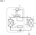
- Fig. 1 is a schematic diagram showing a configuration example of a refrigerant circuit of an air-conditioning apparatus according to Embodiment 1 of the present invention.
- the air-conditioning apparatus includes an indoor unit 1 placed on an indoor side to be air-conditioned and an outdoor unit 2 placed on an outdoor side.
- the indoor unit 1 includes an indoor-side heat exchanger 5.
- the outdoor unit 2 includes a compressor 3, a four-way valve 4, an outdoor-side heat exchanger 6, and an expansion valve 7.
- the compressor 3, four-way valve 4, outdoor-side heat exchanger 6, expansion valve 7, and indoor-side heat exchanger 5 are connected in an annular manner through refrigerant pipes, forming a refrigerant circuit 100.
- the four-way valve 4 is used to switch the air-conditioning apparatus between cooling operation and heating operation and is illustrated in Fig. 1 as having been switched to cooling operation.
- the refrigerant circuit 100 is filled with refrigerant.
- the type of refrigerant is not specifically limited.
- the indoor unit 1 further includes an indoor-side fan 8 for use to send air to the indoor-side heat exchanger 5.
- the indoor-side fan 8 is placed on the windward side of the indoor-side heat exchanger 5.
- the indoor-side fan 8 may be placed on the leeward side of the indoor-side heat exchanger 5.
- the outdoor unit 2 further includes an outdoor-side fan 9 for use to send air to the outdoor-side heat exchanger 6.
- the outdoor-side fan 9 is placed on the leeward side of the outdoor-side heat exchanger 6.
- the four-way valve 4 may be replaced by another selector valve having a similar function.
- a temperature sensor 10 is attached to an outer shell of the compressor 3 of the outdoor unit 2.
- the temperature sensor 10 is used to detect temperature of the compressor 3.
- the temperature sensor 10 may be installed in another location as long as the temperature of the compressor 3 can be estimated, and may be installed on a refrigerant pipe on a route from the compressor 3 to the four-way valve 4 instead of the outer shell of the compressor 3.
- a temperature sensor 11 is attached to the indoor unit 1 on the windward side of the indoor-side fan 8.
- the temperature sensor 11 is used to detect air temperature before inflow into the indoor-side heat exchanger 5, i.e., to detect room temperature. Note that the location of the temperature sensor 11 is not limited to the one shown in Fig. 1 as long as the room temperature can be detected.
- a temperature sensor 12 is attached to a pipe wall of a refrigerant pipe serving as a refrigerant inlet of the outdoor-side heat exchanger 6 during heating.
- the temperature sensor 12 is used to detect evaporating temperature when the outdoor-side heat exchanger 6 functions as an evaporator.
- the temperature sensor 12 may be installed in another location as long as the temperature of the outdoor-side heat exchanger 6 can be estimated.
- the number of temperature sensors is not limited to 3 shown in Fig. 1 , and may be more than 3.
- Information on the temperatures detected by the temperature sensors 10 to 12 is outputted to a control board 20 provided in the outdoor unit 2. Details of the control board 20 will be described later.
- refrigerant is enclosed in the refrigerant circuit 100 and is compressed by the compressor 3.
- refrigerant compressed by the compressor 3 is condensed and liquefied by the outdoor-side heat exchanger 6, expanded by the expansion valve 7, and then evaporated by the indoor-side heat exchanger 5, subsequently returning to the compressor 3 and thereby going through a refrigeration cycle formed by a cooling circuit.
- refrigerant compressed by the compressor 3 is condensed and liquefied by the indoor-side heat exchanger 5, expanded by the expansion valve 7, and evaporated by the outdoor-side heat exchanger 6, subsequently returning to the compressor 3 and thereby going through a refrigeration cycle formed by a heating circuit.
- the air-conditioning device of Fig. 1 controls various parts such that the temperature detected by the indoor-side temperature sensor 11 will conform to a target value. That is, the air-conditioning device controls rotational speed of the compressor 3, an opening degree of the expansion valve 7, a volume of air sent by the indoor-side fan 8, and a volume of air sent by the outdoor-side fan 9. The control is performed based on the temperatures detected by the temperature sensor 10, temperature sensor 11, and temperature sensor 12 and cooling capacity or heating capacity is controlled. This control is performed by the control board 20 of the outdoor unit 2.
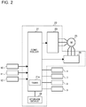
- Fig. 2 is a control block diagram of a control system of the air-conditioning apparatus including the control board 20 of Fig. 1 .
- a controller 21, storage device 22, drive circuit 23, and connection switching device 24 are mounted on the control board 20.
- the controller 21 is made up of a microprocessor or DSP (digital analog processor).
- the controller 21 incorporates a timer 21a.
- the storage device 22 prestores a reference count of thermo-off and stores a thermo-off count, the times at which thermo-off occurred, and other similar data.
- the controller 21 is connected with the drive circuit 23.
- the controller 21 controls output frequency of a three-phase AC voltage outputted from the drive circuit 23.
- the drive circuit 23 outputs the three-phase AC voltage using an inverter and drives a three-phase permanent magnet motor 25 incorporated in the compressor 3.
- the connection switching device 24 switches a connection method for the stator windings of the permanent magnet motor 25 from the delta connection to the star connection or from the star connection to the delta connection. Details of the connection switching device 24 will be described later.
- the electric motor incorporated in the compressor 3 may be a three-phase motor other than a permanent magnet motor.
- thermo-off control and defrosting operation such as described below.
- thermo-off control and defrosting operation will be outlined.
- thermo-off temperature is the target temperature + ⁇ in the case of heating, and the target temperature - ⁇ in the case of cooling.
- thermo-on temperature is the target temperature - ⁇ in the case of heating, and the target temperature + ⁇ in the case of cooling.
- ⁇ and ⁇ are values set as appropriate to avoid hunting resulting from on-off action.
- the thermo-off temperature corresponds to a correction temperature of the present invention, and equals the target temperature when ⁇ is 0.
- Fig. 3 is a timing chart of defrosting control.
- the defrosting operation is an example of operation performed conventionally, and will be outlined below.
- condition a a definite period of time elapses after resumption of heating operation
- condition b a prescribed value Tdef_on
- the controller 21 determines that conditions for starting defrosting operation are satisfied and starts defrosting operation. That is, the controller 21 determines that frost has formed on the outdoor-side heat exchanger 6 and starts defrosting operation.
- the controller 21 In defrosting operation, after stopping the compressor 3, the controller 21 forms a cooling circuit by switching the four-way valve 4 and melts frost by a reverse defrosting method that involves restarting the compressor 3 and circulating the refrigerant. The defrosting operation is continued until the temperature detected by the temperature sensor 12 reaches or exceeds a prescribed value Tdef_off. When the temperature detected by the temperature sensor 12 reaches or exceeds the prescribed value Tdef_off (condition c), the controller 21 determines that a condition for finishing the defrosting operation is satisfied and finishes the defrosting operation. In finishing the defrosting operation, the controller 21 stops the compressor 3 first, returns to the heating circuit by switching the four-way valve 4, and resumes heating operation by restarting the compressor 3. Note that according to the present embodiment, when the stator windings of the permanent magnet motor 25 are star-connected, defrosting operation is also performed under other conditions in addition to the above conditions.
- Fig. 4 is a circuit diagram showing details of the connection switching device 24.
- Fig. 5 is an external view of the compressor 3.
- the compressor 3 incorporates the permanent magnet motor 25.
- the stator windings of the permanent magnet motor 25 are connected to the drive circuit 23 and connection switching device 24.
- Three C contact relays 24a, 24b, and 24c are used as the connection switching device 24.
- the permanent magnet motor 25 has six leads. The six leads are connected to the outside of the compressor 3 through glass terminals 16a and 16b shown in Fig. 5 . Three of the six leads are connected to the drive circuit 23, and the remaining three leads are connected to the three C contact relays 24a, 24b, and 24c, respectively.
- An ⁇ -contact of the C contact relay 24a is connected to a W phase output terminal of the drive circuit 23, and an ⁇ -contact of the C contact relay 24b is connected to a V phase output terminal of the drive circuit 23.
- An ⁇ -contact of the C contact relay 24c is connected to a U phase output terminal of the drive circuit 23.
- a b-contact of the C contact relay 24a, a b-contact of the C contact relay 24b, and a b-contact of the C contact relay 24c are connected with one another.
- connection switching device 24 configured in this way, the delta connection is formed when the relay contacts of the three C contact relays 24a, 24b, and 24c are switched to the a-contact side, and the star connection is formed when the relay contacts are switched to the b-contact side.
- connection switching device 24 is configured such that the star connection will be used when the coils are not energized and that the delta connection will be used when the coils are energized.
- the connection switching device 24 may be configured such that the star connection will be used when the coils are energized and that the delta connection will be used when the coils are not energized.
- the controller 21 performs capacity control in relation to an operating state of the refrigeration cycle based on the temperatures detected by the plural temperature sensors 10 to 12. In the course of the control if conditions for switching to the star connection are satisfied during operation with the delta connection the controller 21 switches the connection from the delta connection to the star connection by controlling the connection switching device 24. In this case, the relay contacts of the C contact relays 24a, 24b, and 24c of the connection switching device 24 are switched from the a-contacts to the b-contacts. On the other hand, if conditions for switching to the delta connection are satisfied during operation with the star connection, the controller 21 switches the connection from the star connection to the delta connection by controlling the connection switching device 24.
- the C contact relays 24a, 24b, and 24c of the connection switching device 24 are switched from the b-contacts to the a-contacts. Furthermore, at the same time with relay switching, the controller 21 switches various control constants used to drive the compressor 3. Note that relay switching is done when the compressor 3 is stopped by taking individual variation of the three relays and product safety into consideration.
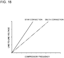
- a motor when a line-to-line voltage is high, because an amount of current required to generate necessary torque is reduced, a motor has high efficiency, but undergoes an increase in an induced voltage. Furthermore, because the induced voltage is proportional to rotation speed, the line-to-line voltage reaches a maximum inverter output at a lower rotation speed. Conversely, when the line-to-line voltage is low, the motor can operate up to a higher rotation speed, but the current needed to generate necessary torque increases. For example, as shown in Fig. 18 , it is a known fact that the line-to-line voltage in the star connection is higher than the line-to-line voltage in the delta connection, and is ⁇ 3 times the delta connection.
- a threshold is determined based solely on compressor frequency or inverter output voltage and switching is done between the delta connection and star connection each time the threshold is crossed, a shutdown has to be caused each time the determined threshold is crossed.
- Such a situation goes against the user's intent.
- the compressor has to be stopped to switch the connection, which increases the number of compressor stops in a season as a whole compared to conventional cases, resulting in lower comfort than conventionally the case.
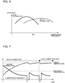
- Fig. 6 is a schematic diagram showing efficiencies of a star connection and delta connection vs. compressor frequency as well as an intersection of efficiency curves. Compressor frequency can be used as one of criteria for determining whether operation with the star connection is more efficient than operation with the delta connection.
- the efficiencies of the star connection and delta connection form curves each having an efficiency peak and superiority in efficiency switches at an intersection (Nc) of the curves. Strictly speaking, the position of the intersection changes with environmental factors such as inside and outside temperatures, but the changes are negligible in considering reductions in annual power consumption under standard conditions, and do not affect the general trend.
- a frequency threshold for switching control between the star connection and delta connection it is sufficient that one efficiency intersection under standard conditions is established as a representative point.
- the use of the delta connection is continued.
- the star connection is used as a principle.
- connection is switched from the above viewpoint.
- connection switching from the delta connection to the star connection and connection switching from the star connection to the delta connection will be described individually.
- Fig. 7 is a schematic diagram showing an example of changes, with time, of compressor frequency in a low-load region during heating.
- the compressor frequency falls.
- thermo-off occurs to stop the compressor 3 (A1, A2). Switching from the delta connection to the star connection during the thermo-off eliminates the need to add a compressor stop for connection switching.
- thermo-off the number of compressor stops due to thermo-off reaches N times and the frequency just before the thermo-off is equal to or lower than the frequency threshold all the N times.
- N 2 as an example, but N may be an integer equal to or larger than 2 and may be set as appropriate according to housing performance.
- thermo-off For example, if a long time passes from the first count to the Nth count there is no point in counting thermo-off cumulatively because it is likely that environmental conditions including outside temperature have changed. Thus, the condition that switching from the delta connection to the star connection is done if thermo-off occurs N times successively within a definite period of time is more appropriate. Also, if a shift to defrosting operation takes place before the thermo-off count reaches N, the thermo-off count is reset. That is, because air-conditioning conditions under which a shift to defrosting operation takes place often require high capacity, the delta connection is maintained.
- thermo-off time continues for a long time
- switching to the star connection may be done by determining that the load is low, i.e., high capacity operation is unnecessary even if the number of times has not reached N.
- a permanent magnet of the electric motor is demagnetized at high temperatures more easily than in the operation with the delta connection. If refrigerant leaks, operation is performed on low refrigerant and discharge temperature tends to rise.
- the temperature detected by the temperature sensor 10 i.e., the temperature of the compressor 3 is equal to or higher than a reference temperature, even if the conditions for switching to the star connection are satisfied, switching to the star connection is not done from the viewpoint of compressor protection.
- the controller 21 performs connection switching control by reflecting the above-mentioned switching conditions and a process of the control will be described based on flowcharts.
- Figs. 8 to 10 are flowcharts showing a control process performed by the controller when switching from the delta connection to the star connection, and computations for the control process are performed concurrently.
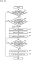
- Fig. 8 is a flowchart (Part 1) of connection switching control for switching stator windings of the electric motor 25 from the delta connection to the star connection, showing an example in which the thermo-off count and compressor frequency are used as conditions.
- the controller 21 determines whether indoor temperature has reached the thermo-off temperature (S11) and enters thermo-off when the thermo-off temperature is reached (S12). With the compressor 3 stopped due to the thermo-off, the following processes are performed.
- the count n is stored in the storage device 22 and the value of the count n is updated. In so doing, the value of the count n and the time at which the count n is reached are stored in the storage device 22 as well.
- the count n indicates the thermo-off count when the indoor temperature reaches the thermo-off temperature, resulting in thermo-off and the compressor frequency just before the thermo-off becomes equal to or lower than the frequency threshold.
- the controller 21 determines whether the count n has reached a set value N (S15).
- step 16 corresponds to a third reference time of the present invention and is set from the viewpoint that a shift to connection switching control should take place after the air-conditioning apparatus enters stable operation.
- step 17 corresponds to a second reference time of the present invention and is set from the viewpoint of determining whether the load is low.
- the controller 21 determines whether the temperature of the compressor 3 is lower than the reference temperature (S18). When it is determined that the temperature of the compressor 3 is equal to or lower than the reference temperature, the controller 21 switches from the delta connection to the star connection by controlling the connection switching device 24 (S19). Here, the C contact relays 24a, 24b, and 24c are switched from the b-contacts to the a-contacts. When the condition is not satisfied (NO) in the determination of any of steps 11, 15, 16 (S11, S15, S16), the processing is finished.
- Fig. 9 is a flowchart (Part 2) of connection switching control for switching the stator windings of the electric motor from the delta connection to the star connection, showing an example in which thermo-off time is reflected as a switching condition.
- the process of the flowchart is started with a start of thermo-off serving as a trigger.
- the controller 21 measures the time duration of the thermo-off state (S21). The time measurement is continued until thermo-on (S23), and when it is determined that the measured time exceeds the reference time (S22), next it is determined whether a connection switching process has already been performed (S24).
- the controller 21 goes to step 19 (S19) of Fig. 8 and performs a connection switching process.
- the reference time in step 22 (S22) corresponds to a first reference time of the present invention.
- Fig. 10 is a flowchart (Part 3) of connection switching control for switching the stator windings of the electric motor from the delta connection to the star connection, showing an example in which a compressor stop is reflected as a switching condition.
- the process of the flowchart is started with a compressor stop serving as a trigger when the compressor stops due to defrosting or an abnormal condition.
- thermo-off occurs N times continuously in the flowchart of Fig. 8 . Note that when it is said that thermo-off occurs N times continuously, this means that the compressor does not stop due to another factor between thermo-off and next thermo-off.
- connection switching control described above is applied to either of heating operation and cooling operation.
- Step (S13) of Fig. 8 may be omitted and the switching process may be performed based solely on the thermo-off count.
- the fact that operation of the air-conditioning apparatus is being continued in a low-load region is determined based on continuous occurrence of thermo-off and operation in non-low-load region (i.e., high-load region) is determined based on occurrence of defrosting.
- the air-conditioning apparatus has a means of detecting or estimating air conditioning loads, determination of air conditioning loads may be made based on detection information or estimation information on the air conditioning loads.
- the present embodiment switches connection from the delta connection to the star connection, offering the following advantageous effects.
- the connection switching device 24 switches connection from the delta connection to the star connection during a thermo-off period. That is, switching from the delta connection to the star connection is done in synchronization with thermo-off.
- This makes it possible to switch connection without increasing stop frequency of the compressor 3 compared to conventional stop frequency and thereby reduce unpleasantness caused by a compressor stop during connection switching.
- the shift from the delta connection to the star connection improves energy efficiency. Also, accuracy of determination as to which connection is more appropriate for operation is increased. This makes it possible to reduce unnecessary connection switching and maintain comfort. In this way, the present embodiment combines energy efficiency in a low-load region and high capacity in a high-load region without impairing comfort.
- connection is switched when the thermo-off count reaches the reference count N and a state in which an operating frequency of the compressor 3 during thermo-off is equal to or lower than the frequency threshold continues to amount to the reference count N.
- connection is switched by taking into consideration the thermo-off count and the operating frequency of the compressor 3 during thermo-off. This further increases accuracy of determination on switching to the star connection, making it possible to combine energy efficiency in a low-load region and high capacity in a high-load region without impairing comfort.
- thermo-off time reaches or exceeds the first reference time
- connection is switched regardless of the thermo-off count and compressor frequency.
- a duration of thermo-off reaches or exceeds a definite period of time
- high capacity operation of the compressor 3 is unnecessary and connection is switched from the viewpoint of energy efficiency.
- thermo-off count is reset. If a long period of time is required until the reference count N is reached, the compressor 3 is in a driving state that cannot be said to be in a low-load region. Therefore, the driving state with the stator windings delta-connected is maintained.
- thermo-off count is reset.
- defrosting operation is performed to remove frost from the outdoor-side heat exchanger 6, the thermo-off count is reset.
- the fact that defrosting operation was performed means that the compressor 3 is not in a low-load state, and thus operation is continued with the stator windings delta-connected.
- connection switching is not controlled regardless of the presence or absence of the switching conditions. This is because for a definite period of time after the start of operation of the air-conditioning apparatus, the operation is transitional and accuracy of load determination is low, and thus connection is switched when the operation is stabilized.
- connection is switched in the thermo-off period in which the reference count is reached.
- Fig. 11 is a schematic diagram showing an example of changes, with time, of compressor frequency during heating if load fluctuations occur.
- the air conditioning load acts in such a direction as to require high capacity, and thus it is desirable that the time until a restart is short.
- the time taken to eliminate differential pressure in the refrigerant circuit 100 is reduced by switching the four-way valve 4 and thereby reversing a refrigerant circulation before and after defrosting operation. That is, by inserting defrosting operation during switching from the star connection to the delta connection in heating operation, the waiting time for equalization of refrigerant pressure to prevent compressor failures is reduced. Consequently, downtime for connection switching can be reduced while curbing increases in the number of times of defrosting in the entire heating period, and switching can be done while maintaining comfort.
- Air conditioning load fluctuations are temporary, and even if high frequency is required temporarily, if the air conditioning load goes toward stabilization when the compressor frequency falls below the frequency threshold again between B2 and B3 or if it is determined, based on air conditioning load detection information, estimation information, or other information, that operation at a frequency lower than the frequency threshold Nc will continue, switching from the star connection to the delta connection does not have to be done. For example, if the compressor frequency is lower than Nc between B2 and B3, switching from the star connection to the delta connection does not have to be done.
- Fig. 12 is a schematic diagram showing an example of changes, with time, of compressor frequency during heating if target value fluctuations occur.
- the target temperature rises at time C1, and the compressor frequency increases accordingly. Since operation is performed at frequencies above the frequency threshold Nc at time C1a, even though it is appropriate to operate using the delta connection, an attempt to perform a connection switching operation by stopping the compressor just after changing the set temperature runs counter to the intent of the user who is trying to increase the room temperature and will cause the user to feel odd.
- the room temperature is increased with the star connection kept as it is until time C2, switching to the delta connection is done between C2 and C3, defrosting operation is started at C3, and heating operation is resumed at C4.
- the indoor temperature reaches the target temperature and thermo-off occurs between C1 and C2, the operation of switching to the delta connection does not have to be done.
- Fig. 13 is a flowchart (Part 1) of connection switching control for switching the stator windings of the electric motor from the star connection to the delta connection, showing an example in which operating time and outdoor-side heat exchanger temperature are used as start conditions of defrosting operation.
- the connection switching control is performed when the stator windings of the permanent magnet motor 25 are star-connected.
- the controller 21 determines whether a definite period of time has passed since the start of heating operation after an end of defrosting (S31). When it is determined that a definite period of time has passed, next the controller 21 determines whether the temperature detected by the temperature sensor 12 is equal to or lower than the prescribed value (Tdef_on) (S32).
- the controller 21 determines that a condition for starting defrosting operation is satisfied. However, in the present embodiment, instead of shifting to defrosting operation immediately, first the controller 21 stops the compressor 3 (S33). With the compressor 3 stopped, the controller 21 switches from the star connection to the delta connection by controlling the connection switching device 24 (S34). Subsequently, the controller 21 starts defrosting operation using the delta connection (S35). That is, the controller 21 forms a cooling circuit by switching the four-way valve 4 and melts frost by the reverse defrosting method that involves restarting the compressor 3 and circulating the refrigerant.
- the defrosting operation is continued until the temperature detected by the temperature sensor 12 reaches or exceeds the prescribed value (Tdef_off) (S36).
- the controller 21 finishes the defrosting operation (S37). In finishing the defrosting operation, first the controller 21 stops the compressor 3, returns to the heating circuit by switching the four-way valve 4, and resumes heating operation by restarting the compressor 3 (S38).
- step 31 (S31) above may be omitted.
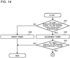
- Fig. 14 is a flowchart (Part 2) of connection switching control for switching the stator windings of the electric motor from the star connection to the delta connection, showing an example in which compressor frequency is used as a start condition of defrosting operation.
- the process of the flow chart is performed periodically.
- the controller 21 determines whether the compressor frequency is equal to or higher than the frequency threshold (S41). When it is determined that the compressor frequency is equal to or higher than the frequency threshold, the built-in timer 21a is incremented (S42). When the condition is not satisfied in step 41 (S41), the timer 21a is reset (S44). The controller 21 determines whether the value of the timer 21a is equal to or higher than a default value (S43).
- step 33 (S33) of Fig. 13 When the value of the timer 21a is equal to or higher than the default value, the controller 21 goes to step 33 (S33) of Fig. 13 by determining that the condition for the defrosting has been satisfied and carries out step 33 (S33) and subsequent processes of Fig. 13 .
- Fig. 15 is a flowchart (Part 3) of connection switching control for switching the stator windings of the electric motor from the star connection to the delta connection, showing an example in which the temperature of the compressor 3 is used as a start condition of defrosting operation.
- the controller 21 determines whether the temperature detected by the temperature sensor 10, i.e., the temperature of the compressor 3, exceeds reference temperature (S47). When the reference temperature is exceeded, the controller 21 goes to step 33 (S33) of Fig. 13 and carries out step 33 (S33) and subsequent processes of Fig. 13 .
- the reference temperature in step 47 (S47) above is set from the viewpoint of protecting the compressor 3. The above description assumes heating operation, and in the case of cooling operation, the cooling operation is continued after the connection switching process by omitting defrosting control.
- FIG. 16 which corresponds to Fig. 11 , is a schematic diagram showing an example of changes, with time, of the compressor operating current during heating if load fluctuations occur. In this example, connection is switched under conditions that a state in which the room temperature is lower than the target temperature and the operating current of the compressor 3 is higher than an operating current threshold Ic continues for a definite period of time.
- Fig. 17 is a variation of Fig. 14 and is an example in which the operating current of the compressor 3 is used as a start condition of defrosting operation.
- Step 41 (S41) of Fig. 14 is replaced with step 41a (S41a).
- the controller 21 determines whether the operating current of the compressor 3 is equal to or higher than the operating current threshold Ic (S41a). When it is determined that the operating current of the compressor 3 is equal to or higher than the operating current threshold Ic, the built-in timer 21a is incremented (S42).
- the other processes are the same as the processes of Fig. 14 . Connection switching and defrosting are done under a condition that a state in which the operating current of the compressor 3 is higher than the operating current threshold Ic continues for a definite period of time.
- the present embodiment switches connection from the star connection to the delta connection, offering the following advantageous effects.
- the connection of the stator windings is switched from the star connection to the delta connection. That is, switching from the star connection to the delta connection is done in synchronization with defrosting operation.
- This makes it possible to switch connection without increasing the stop frequency of the compressor 3 compared to conventional stop frequency and thereby reduce unpleasantness caused by a compressor stop during connection switching.
- the shift from the star connection to the delta connection provides high capacity in a high-load region.
- the accuracy of determination as to which connection is more appropriate for operation is increased. This makes it possible to reduce unnecessary connection switching and maintain comfort. In this way, the present embodiment combines energy efficiency in a low-load region and high capacity in a high-load region without impairing comfort.
- connection switching from the star connection to the delta connection is done in conjunction with defrosting operation.
- This makes it possible to switch connection without increasing the stop frequency of the compressor 3 compared to conventional stop frequency and thereby reduce unpleasantness caused by a compressor stop during connection switching.
- the shift from the star connection to the delta connection provides high capacity in a high-load region.
- the accuracy of determination as to which connection is more appropriate for operation is increased. This makes it possible to reduce unnecessary connection switching and maintain comfort. In this way, the present embodiment combines energy efficiency in a low-load region and high capacity in a high-load region without impairing comfort.
- connection of the stator windings is switched from the star connection to the delta connection using the connection switching device 24. This further increases accuracy of determination on switching to the delta connection.
- the connection of the stator windings is switched from the star connection to the delta connection. This further increases the accuracy of determination on switching to the delta connection.
- the connection of the stator windings is switched from the star connection to the delta connection. This further increases the accuracy of determination on switching to the delta connection.
- the connection of the stator windings is switched from the star connection to the delta connection.
- the operation in this case may be either heating or cooling, and from the viewpoint of protection of the compressor 3, the delta connection is used for the stator windings.
- a shift to defrosting operation is made after connection switching.
- the defrosting operation is performed after the connection of the stator windings is switched from the star connection to the delta connection. That is, the switching from the star connection to the delta connection is done in synchronization with defrosting operation. This makes it possible to switch connection without increasing the stop frequency of the compressor 3 compared to conventional stop frequency and thereby reduce unpleasantness caused by a compressor stop during connection switching.
- connection switching device 24 by stopping the compressor 3, the connection switching device 24 is caused to switch connection, with the compressor 3 stopped. Consequently, even if there is variation in operating characteristics of the C contact relays 24a to 24c making up the connection switching device 24, safety of products is ensured without inconvenience.
Claims (8)
- Klimaanlage, umfassend:einen Verdichter (3), mit eingebautem Elektromotor (25);einen Temperatursensor (11), der eingerichtet ist, eine Innentemperatur zu erfassen;eine Antriebsschaltung (23), die eingerichtet ist, den Elektromotor (25) anzutreiben;eine Verbindungsschalteinrichtung (24), die eingerichtet ist, eine Verbindung von Statorwicklungen des Elektromotors (25) zwischen einem ersten Verbindungszustand und einem zweiten Verbindungszustand, der höher in einer Leitung-zu-Leitung-Spannung ist als der erste Verbindungszustand, zu schalten; wobei in dem ersten Verbindungszustand die Statorwicklungen im Dreieck verbunden sind und in dem zweiten Verbindungszustand die Statorwicklungen im Stern verbunden sind; undeine Steuereinheit (21), die eingerichtet ist, in eine Thermoabschaltung einzutreten, wenn die Innentemperatur eine Zieltemperatur oder eine auf der Grundlage der Zieltemperatur eingestellte Korrekturtemperatur erreicht, und die Verbindungsschalteinrichtung (24) zu veranlassen, eine Verbindung zu schalten, wobei die Thermoabschaltung durch Anhalten des Verdichters (3) über die Antriebsschaltung (23) erreicht wird, dadurch gekennzeichnet, dass, wenn ein Thermoabschaltungszählwert einen Referenzzählwert erreicht, während sich der Elektromotor (25) in dem ersten Verbindungszustand befindet, die Steuereinheit (21) die Verbindungsschalteinrichtung (24) veranlasst, die Verbindung der Statorwicklungen während der Thermoabschaltung von dem ersten Verbindungszustand zu dem zweiten Verbindungszustand zu schalten;wobei die Klimaanlage ferner einen Temperatursensor (10) umfasst, der eingerichtet ist, eine Temperatur des Verdichters (3) zu erfassen, wobeiwenn der Elektromotor (25) im ersten Verbindungszustand arbeitet, die Steuereinheit (21) die Verbindungsschaltung nicht steuert, um vom ersten Verbindungszustand in den zweiten Verbindungszustand zu schalten, wenn die Temperatur des Verdichters (3) gleich oder höher als eine Referenztemperatur ist, selbst wenn eine Bedingung für das Schalten vom ersten Verbindungszustand in den zweiten Verbindungszustand erfüllt ist.
- Klimaanlage nach Anspruch 1, wobei die Steuereinheit (21) eingerichtet ist, die Zeitdauer des Thermoabschaltungszustands zu messen (S21), die Zeitmessung bis zur Thermoeinschaltung fortgesetzt wird (S23), und wenn bestimmt wird, dass die gemessene Zeit eine erste Referenzzeit überschreitet (S22), als nächstes bestimmt wird, ob bereits ein Verbindungsschaltprozess durchgeführt wurde (S24), wenn bestimmt wird, dass noch kein Verbindungsschaltprozess durchgeführt wurde, die Steuereinheit (21) die Verbindungsschalteinrichtung (24) veranlasst, die Verbindung vom ersten Verbindungszustand in den zweiten Verbindungszustand zu schalten.
- Klimaanlage nach einem der Ansprüche 1 bis 2, wobei wenn eine zweite Referenzzeit während einer Zeitspanne von einem ersten Zählwert einer Thermoabschaltung bis der Referenzzählwert erreicht ist, überschritten ist, die Steuereinheit (21) den Thermoabschaltungszählwert zurücksetzt.
- Klimaanlage nach einem der Ansprüche 1 bis 3, wobei wenn die Steuereinheit einen Entfrostungsbetrieb durchführt, um Frost von einem außenseitigen Wärmetauscher (6) zu entfernen, die Steuereinheit (21) den Thermoabschaltungszählwert zurücksetzt.
- Klimaanlage nach einem der Ansprüche 1 bis 4, wobei die Steuereinheit (21) nicht die Verbindungsschaltung vor Ablauf einer dritten Referenzzeit von einem Beginn eines Betriebs der Klimaanlage an steuert.
- Klimaanlage nach einem der Ansprüche 1 bis 5, wobei während eines Betriebs, bei dem sich die Statorwicklungen im zweiten Verbindungszustand befinden, wenn eine Temperatur des Verdichters (3) eine Referenztemperatur überschreitet, die Steuereinheit (21) die Verbindungsschalteinrichtung (24) veranlasst, die Verbindung der Statorwicklungen vom zweiten Verbindungszustand in den ersten Verbindungszustand zu schalten.
- Klimaanlage nach einem der Ansprüche 1 bis 6, ferner umfassend eine Speichereinrichtung (22), wobei
die Speichereinrichtung (22) den Referenzzählwert vorspeichert und den Thermoabschaltungszählwert speichert. - Klimaanlage nach einem der Ansprüche 1 bis 7, wobei im ersten Verbindungszustand die Statorwicklungen auf einer Phase-für-Phase-Basis parallel verbunden sind und im zweiten Verbindungszustand die Statorwicklungen auf einer Phase-für-Phase-Basis in Reihe verbunden sind.
Applications Claiming Priority (1)
| Application Number | Priority Date | Filing Date | Title |
|---|---|---|---|
| PCT/JP2017/029516 WO2019035195A1 (ja) | 2017-08-17 | 2017-08-17 | 空気調和機 |
Publications (3)
| Publication Number | Publication Date |
|---|---|
| EP3671064A1 EP3671064A1 (de) | 2020-06-24 |
| EP3671064A4 EP3671064A4 (de) | 2020-07-01 |
| EP3671064B1 true EP3671064B1 (de) | 2021-08-04 |
Family
ID=65361875
Family Applications (1)
| Application Number | Title | Priority Date | Filing Date |
|---|---|---|---|
| EP17921841.7A Active EP3671064B1 (de) | 2017-08-17 | 2017-08-17 | Klimaanlage |
Country Status (5)
| Country | Link |
|---|---|
| US (1) | US11150000B2 (de) |
| EP (1) | EP3671064B1 (de) |
| JP (1) | JP6821034B2 (de) |
| CN (1) | CN111033140B (de) |
| WO (1) | WO2019035195A1 (de) |
Families Citing this family (3)
| Publication number | Priority date | Publication date | Assignee | Title |
|---|---|---|---|---|
| CN111033143B (zh) * | 2017-08-17 | 2021-06-11 | 三菱电机株式会社 | 空调机 |
| CN113811723A (zh) * | 2019-05-20 | 2021-12-17 | 三菱电机株式会社 | 室外机、空气调节装置以及空气调节装置的运转控制方法 |
| CN112902384A (zh) * | 2021-02-23 | 2021-06-04 | 宁波奥克斯电气股份有限公司 | 空调压缩机的快速启动控制方法、装置和空调器 |
Family Cites Families (21)
| Publication number | Priority date | Publication date | Assignee | Title |
|---|---|---|---|---|
| US3750447A (en) | 1971-09-28 | 1973-08-07 | Imp Eastman Corp | Tube bender |
| US3874187A (en) * | 1974-04-26 | 1975-04-01 | Fedders Corp | Refrigerant compressor with overload protector |
| US4186563A (en) * | 1978-04-24 | 1980-02-05 | General Electric Company | Cooling efficiency meter circuit for an air conditioner |
| JP3293316B2 (ja) * | 1994-04-19 | 2002-06-17 | 松下電器産業株式会社 | 自動車用電動圧縮機の制御駆動装置 |
| US20010045101A1 (en) * | 2000-02-11 | 2001-11-29 | Graham Donald E. | Locomotive air conditioner control system and related methods |
| JP2002061925A (ja) * | 2000-08-23 | 2002-02-28 | Daikin Ind Ltd | 空気調和装置 |
| US20050155369A1 (en) * | 2004-01-15 | 2005-07-21 | Toshiba Carrier Corporation | Air conditioner |
| JP4722069B2 (ja) | 2007-03-15 | 2011-07-13 | 三菱電機株式会社 | 電動機駆動装置および電動機駆動方法並びに冷凍空調装置 |
| JP2009216324A (ja) * | 2008-03-11 | 2009-09-24 | Toshiba Carrier Corp | 空気調和機 |
| JP5468215B2 (ja) * | 2008-06-09 | 2014-04-09 | ダイキン工業株式会社 | 空気調和機及び空気調和機の製造方法 |
| JP2011067079A (ja) | 2009-09-18 | 2011-03-31 | Toshiba Carrier Corp | 空気調和機 |
| JP5501132B2 (ja) * | 2010-07-22 | 2014-05-21 | 日立アプライアンス株式会社 | 空気調和機 |
| CN102868216A (zh) * | 2011-07-08 | 2013-01-09 | 杨鸣峰 | 一种智能功率分配方法及装置 |
| CN103795304B (zh) * | 2012-11-01 | 2015-11-25 | 珠海格力节能环保制冷技术研究中心有限公司 | 三相同步电动机驱动控制系统及控制方法 |
| CN104374036B (zh) * | 2013-08-14 | 2018-08-17 | 浙江盾安人工环境股份有限公司 | 空调的控制方法和空调机组 |
| US9353738B2 (en) * | 2013-09-19 | 2016-05-31 | Emerson Climate Technologies, Inc. | Compressor crankcase heating control systems and methods |
| WO2015053939A1 (en) * | 2013-10-09 | 2015-04-16 | Johnson Controls Technology Company | Motor housing temperature control system |
| JP5932759B2 (ja) * | 2013-11-21 | 2016-06-08 | 三菱電機株式会社 | 空気調和機 |
| CN104227502B (zh) * | 2014-08-12 | 2016-06-01 | 广东润星科技股份有限公司 | 一种具有三相电源智能相序检测与判断功能的温控器 |
| CN104676796B (zh) * | 2015-02-28 | 2018-08-31 | 广东美的暖通设备有限公司 | 空调系统及其控制方法 |
| CN105762924A (zh) * | 2016-04-23 | 2016-07-13 | 国家电网公司 | 可移动式快速固态电源切换开关装置 |
-
2017
- 2017-08-17 WO PCT/JP2017/029516 patent/WO2019035195A1/ja unknown
- 2017-08-17 US US16/621,954 patent/US11150000B2/en active Active
- 2017-08-17 JP JP2019536390A patent/JP6821034B2/ja active Active
- 2017-08-17 EP EP17921841.7A patent/EP3671064B1/de active Active
- 2017-08-17 CN CN201780093889.4A patent/CN111033140B/zh active Active
Also Published As
| Publication number | Publication date |
|---|---|
| WO2019035195A1 (ja) | 2019-02-21 |
| CN111033140A (zh) | 2020-04-17 |
| EP3671064A1 (de) | 2020-06-24 |
| US20200173703A1 (en) | 2020-06-04 |
| JP6821034B2 (ja) | 2021-01-27 |
| CN111033140B (zh) | 2021-06-25 |
| US11150000B2 (en) | 2021-10-19 |
| JPWO2019035195A1 (ja) | 2020-02-27 |
| EP3671064A4 (de) | 2020-07-01 |
Similar Documents
| Publication | Publication Date | Title |
|---|---|---|
| EP3671057B1 (de) | Klimaanlage | |
| EP0645589B1 (de) | Steuergerät zum betreiben einer klimaanlage | |
| JP3766088B2 (ja) | 空気調和機及びその制御方法 | |
| EP3671064B1 (de) | Klimaanlage | |
| JP4972532B2 (ja) | 空気調和機 | |
| WO2013016436A1 (en) | Loading and unloading of compressors in a cooling system | |
| KR20130106292A (ko) | 모터 제어 장치, 이를 이용한 모터 구동 장치, 압축기, 냉동 장치, 공기 조화기, 및 모터 제어 방법 | |
| WO2018179137A1 (ja) | 空気調和装置 | |
| JP5686754B2 (ja) | 空気調和機 | |
| EP1094220B1 (de) | Klimaregelung | |
| KR100545958B1 (ko) | 공기 조화 장치 및 공기 조화 장치의 제어 방법 | |
| WO2023221664A1 (zh) | 多联机空调系统的控制方法、控制装置和多联机空调系统 | |
| JP2689599B2 (ja) | 空気調和装置の運転制御装置 | |
| JPS59189243A (ja) | 空気調和機の除霜制御装置 | |
| JPH0618103A (ja) | 空気調和機 | |
| JPH07332730A (ja) | 空気調和機 | |
| JPH0721345B2 (ja) | 空気調和装置の制御装置 | |
| JP2008136329A (ja) | 冷凍装置 | |
| JP2005300056A (ja) | 冷凍サイクル装置 | |
| JP3220487B2 (ja) | 空気調和機の制御装置 | |
| JPH06221706A (ja) | 多室型空気調和装置 | |
| JPH07174416A (ja) | 冷凍サイクル装置 | |
| JPH04236072A (ja) | 空気調和装置 | |
| KR20020017575A (ko) | 냉장고의 소음절감운전방법 | |
| JP2017203594A (ja) | 空気調和機 |
Legal Events
| Date | Code | Title | Description |
|---|---|---|---|
| STAA | Information on the status of an ep patent application or granted ep patent |
Free format text: STATUS: THE INTERNATIONAL PUBLICATION HAS BEEN MADE |
|
| PUAI | Public reference made under article 153(3) epc to a published international application that has entered the european phase |
Free format text: ORIGINAL CODE: 0009012 |
|
| STAA | Information on the status of an ep patent application or granted ep patent |
Free format text: STATUS: REQUEST FOR EXAMINATION WAS MADE |
|
| 17P | Request for examination filed |
Effective date: 20200131 |
|
| AK | Designated contracting states |
Kind code of ref document: A1 Designated state(s): AL AT BE BG CH CY CZ DE DK EE ES FI FR GB GR HR HU IE IS IT LI LT LU LV MC MK MT NL NO PL PT RO RS SE SI SK SM TR |
|
| AX | Request for extension of the european patent |
Extension state: BA ME |
|
| A4 | Supplementary search report drawn up and despatched |
Effective date: 20200604 |
|
| RIC1 | Information provided on ipc code assigned before grant |
Ipc: F25B 49/02 20060101ALI20200528BHEP Ipc: H02P 25/18 20060101ALI20200528BHEP Ipc: F25B 13/00 20060101AFI20200528BHEP |
|
| DAV | Request for validation of the european patent (deleted) | ||
| DAX | Request for extension of the european patent (deleted) | ||
| GRAP | Despatch of communication of intention to grant a patent |
Free format text: ORIGINAL CODE: EPIDOSNIGR1 |
|
| STAA | Information on the status of an ep patent application or granted ep patent |
Free format text: STATUS: GRANT OF PATENT IS INTENDED |
|
| INTG | Intention to grant announced |
Effective date: 20210222 |
|
| GRAS | Grant fee paid |
Free format text: ORIGINAL CODE: EPIDOSNIGR3 |
|
| GRAA | (expected) grant |
Free format text: ORIGINAL CODE: 0009210 |
|
| STAA | Information on the status of an ep patent application or granted ep patent |
Free format text: STATUS: THE PATENT HAS BEEN GRANTED |
|
| AK | Designated contracting states |
Kind code of ref document: B1 Designated state(s): AL AT BE BG CH CY CZ DE DK EE ES FI FR GB GR HR HU IE IS IT LI LT LU LV MC MK MT NL NO PL PT RO RS SE SI SK SM TR |
|
| REG | Reference to a national code |
Ref country code: GB Ref legal event code: FG4D |
|
| REG | Reference to a national code |
Ref country code: AT Ref legal event code: REF Ref document number: 1417367 Country of ref document: AT Kind code of ref document: T Effective date: 20210815 |
|
| REG | Reference to a national code |
Ref country code: CH Ref legal event code: EP |
|
| REG | Reference to a national code |
Ref country code: DE Ref legal event code: R096 Ref document number: 602017043651 Country of ref document: DE |
|
| REG | Reference to a national code |
Ref country code: IE Ref legal event code: FG4D |
|
| REG | Reference to a national code |
Ref country code: LT Ref legal event code: MG9D |
|
| REG | Reference to a national code |
Ref country code: NL Ref legal event code: MP Effective date: 20210804 |
|
| REG | Reference to a national code |
Ref country code: AT Ref legal event code: MK05 Ref document number: 1417367 Country of ref document: AT Kind code of ref document: T Effective date: 20210804 |
|
| PG25 | Lapsed in a contracting state [announced via postgrant information from national office to epo] |
Ref country code: SE Free format text: LAPSE BECAUSE OF FAILURE TO SUBMIT A TRANSLATION OF THE DESCRIPTION OR TO PAY THE FEE WITHIN THE PRESCRIBED TIME-LIMIT Effective date: 20210804 Ref country code: RS Free format text: LAPSE BECAUSE OF FAILURE TO SUBMIT A TRANSLATION OF THE DESCRIPTION OR TO PAY THE FEE WITHIN THE PRESCRIBED TIME-LIMIT Effective date: 20210804 Ref country code: HR Free format text: LAPSE BECAUSE OF FAILURE TO SUBMIT A TRANSLATION OF THE DESCRIPTION OR TO PAY THE FEE WITHIN THE PRESCRIBED TIME-LIMIT Effective date: 20210804 Ref country code: FI Free format text: LAPSE BECAUSE OF FAILURE TO SUBMIT A TRANSLATION OF THE DESCRIPTION OR TO PAY THE FEE WITHIN THE PRESCRIBED TIME-LIMIT Effective date: 20210804 Ref country code: ES Free format text: LAPSE BECAUSE OF FAILURE TO SUBMIT A TRANSLATION OF THE DESCRIPTION OR TO PAY THE FEE WITHIN THE PRESCRIBED TIME-LIMIT Effective date: 20210804 Ref country code: PT Free format text: LAPSE BECAUSE OF FAILURE TO SUBMIT A TRANSLATION OF THE DESCRIPTION OR TO PAY THE FEE WITHIN THE PRESCRIBED TIME-LIMIT Effective date: 20211206 Ref country code: NO Free format text: LAPSE BECAUSE OF FAILURE TO SUBMIT A TRANSLATION OF THE DESCRIPTION OR TO PAY THE FEE WITHIN THE PRESCRIBED TIME-LIMIT Effective date: 20211104 Ref country code: LT Free format text: LAPSE BECAUSE OF FAILURE TO SUBMIT A TRANSLATION OF THE DESCRIPTION OR TO PAY THE FEE WITHIN THE PRESCRIBED TIME-LIMIT Effective date: 20210804 Ref country code: BG Free format text: LAPSE BECAUSE OF FAILURE TO SUBMIT A TRANSLATION OF THE DESCRIPTION OR TO PAY THE FEE WITHIN THE PRESCRIBED TIME-LIMIT Effective date: 20211104 Ref country code: AT Free format text: LAPSE BECAUSE OF FAILURE TO SUBMIT A TRANSLATION OF THE DESCRIPTION OR TO PAY THE FEE WITHIN THE PRESCRIBED TIME-LIMIT Effective date: 20210804 |
|
| PG25 | Lapsed in a contracting state [announced via postgrant information from national office to epo] |
Ref country code: PL Free format text: LAPSE BECAUSE OF FAILURE TO SUBMIT A TRANSLATION OF THE DESCRIPTION OR TO PAY THE FEE WITHIN THE PRESCRIBED TIME-LIMIT Effective date: 20210804 Ref country code: LV Free format text: LAPSE BECAUSE OF FAILURE TO SUBMIT A TRANSLATION OF THE DESCRIPTION OR TO PAY THE FEE WITHIN THE PRESCRIBED TIME-LIMIT Effective date: 20210804 Ref country code: GR Free format text: LAPSE BECAUSE OF FAILURE TO SUBMIT A TRANSLATION OF THE DESCRIPTION OR TO PAY THE FEE WITHIN THE PRESCRIBED TIME-LIMIT Effective date: 20211105 |
|
| REG | Reference to a national code |
Ref country code: CH Ref legal event code: PL |
|
| PG25 | Lapsed in a contracting state [announced via postgrant information from national office to epo] |
Ref country code: NL Free format text: LAPSE BECAUSE OF FAILURE TO SUBMIT A TRANSLATION OF THE DESCRIPTION OR TO PAY THE FEE WITHIN THE PRESCRIBED TIME-LIMIT Effective date: 20210804 |
|
| REG | Reference to a national code |
Ref country code: BE Ref legal event code: MM Effective date: 20210831 |
|
| PG25 | Lapsed in a contracting state [announced via postgrant information from national office to epo] |
Ref country code: LI Free format text: LAPSE BECAUSE OF NON-PAYMENT OF DUE FEES Effective date: 20210831 Ref country code: DK Free format text: LAPSE BECAUSE OF FAILURE TO SUBMIT A TRANSLATION OF THE DESCRIPTION OR TO PAY THE FEE WITHIN THE PRESCRIBED TIME-LIMIT Effective date: 20210804 Ref country code: CH Free format text: LAPSE BECAUSE OF NON-PAYMENT OF DUE FEES Effective date: 20210831 |
|
| REG | Reference to a national code |
Ref country code: DE Ref legal event code: R097 Ref document number: 602017043651 Country of ref document: DE |
|
| PG25 | Lapsed in a contracting state [announced via postgrant information from national office to epo] |
Ref country code: SM Free format text: LAPSE BECAUSE OF FAILURE TO SUBMIT A TRANSLATION OF THE DESCRIPTION OR TO PAY THE FEE WITHIN THE PRESCRIBED TIME-LIMIT Effective date: 20210804 Ref country code: SK Free format text: LAPSE BECAUSE OF FAILURE TO SUBMIT A TRANSLATION OF THE DESCRIPTION OR TO PAY THE FEE WITHIN THE PRESCRIBED TIME-LIMIT Effective date: 20210804 Ref country code: RO Free format text: LAPSE BECAUSE OF FAILURE TO SUBMIT A TRANSLATION OF THE DESCRIPTION OR TO PAY THE FEE WITHIN THE PRESCRIBED TIME-LIMIT Effective date: 20210804 Ref country code: MC Free format text: LAPSE BECAUSE OF FAILURE TO SUBMIT A TRANSLATION OF THE DESCRIPTION OR TO PAY THE FEE WITHIN THE PRESCRIBED TIME-LIMIT Effective date: 20210804 Ref country code: LU Free format text: LAPSE BECAUSE OF NON-PAYMENT OF DUE FEES Effective date: 20210817 Ref country code: EE Free format text: LAPSE BECAUSE OF FAILURE TO SUBMIT A TRANSLATION OF THE DESCRIPTION OR TO PAY THE FEE WITHIN THE PRESCRIBED TIME-LIMIT Effective date: 20210804 Ref country code: CZ Free format text: LAPSE BECAUSE OF FAILURE TO SUBMIT A TRANSLATION OF THE DESCRIPTION OR TO PAY THE FEE WITHIN THE PRESCRIBED TIME-LIMIT Effective date: 20210804 Ref country code: AL Free format text: LAPSE BECAUSE OF FAILURE TO SUBMIT A TRANSLATION OF THE DESCRIPTION OR TO PAY THE FEE WITHIN THE PRESCRIBED TIME-LIMIT Effective date: 20210804 |
|
| PLBE | No opposition filed within time limit |
Free format text: ORIGINAL CODE: 0009261 |
|
| STAA | Information on the status of an ep patent application or granted ep patent |
Free format text: STATUS: NO OPPOSITION FILED WITHIN TIME LIMIT |
|
| 26N | No opposition filed |
Effective date: 20220506 |
|
| GBPC | Gb: european patent ceased through non-payment of renewal fee |
Effective date: 20211104 |
|
| PG25 | Lapsed in a contracting state [announced via postgrant information from national office to epo] |
Ref country code: IE Free format text: LAPSE BECAUSE OF NON-PAYMENT OF DUE FEES Effective date: 20210817 Ref country code: BE Free format text: LAPSE BECAUSE OF NON-PAYMENT OF DUE FEES Effective date: 20210831 |
|
| PG25 | Lapsed in a contracting state [announced via postgrant information from national office to epo] |
Ref country code: SI Free format text: LAPSE BECAUSE OF FAILURE TO SUBMIT A TRANSLATION OF THE DESCRIPTION OR TO PAY THE FEE WITHIN THE PRESCRIBED TIME-LIMIT Effective date: 20210804 |
|
| PG25 | Lapsed in a contracting state [announced via postgrant information from national office to epo] |
Ref country code: FR Free format text: LAPSE BECAUSE OF NON-PAYMENT OF DUE FEES Effective date: 20211004 |
|
| PG25 | Lapsed in a contracting state [announced via postgrant information from national office to epo] |
Ref country code: GB Free format text: LAPSE BECAUSE OF NON-PAYMENT OF DUE FEES Effective date: 20211104 |
|
| P01 | Opt-out of the competence of the unified patent court (upc) registered |
Effective date: 20230512 |
|
| PG25 | Lapsed in a contracting state [announced via postgrant information from national office to epo] |
Ref country code: CY Free format text: LAPSE BECAUSE OF FAILURE TO SUBMIT A TRANSLATION OF THE DESCRIPTION OR TO PAY THE FEE WITHIN THE PRESCRIBED TIME-LIMIT Effective date: 20210804 |
|
| PG25 | Lapsed in a contracting state [announced via postgrant information from national office to epo] |
Ref country code: HU Free format text: LAPSE BECAUSE OF FAILURE TO SUBMIT A TRANSLATION OF THE DESCRIPTION OR TO PAY THE FEE WITHIN THE PRESCRIBED TIME-LIMIT; INVALID AB INITIO Effective date: 20170817 |
|
| PGFP | Annual fee paid to national office [announced via postgrant information from national office to epo] |
Ref country code: TR Payment date: 20230814 Year of fee payment: 7 Ref country code: IT Payment date: 20230711 Year of fee payment: 7 |
|
| PGFP | Annual fee paid to national office [announced via postgrant information from national office to epo] |
Ref country code: DE Payment date: 20230627 Year of fee payment: 7 |
|
| PG25 | Lapsed in a contracting state [announced via postgrant information from national office to epo] |
Ref country code: MK Free format text: LAPSE BECAUSE OF FAILURE TO SUBMIT A TRANSLATION OF THE DESCRIPTION OR TO PAY THE FEE WITHIN THE PRESCRIBED TIME-LIMIT Effective date: 20210804 |