EP3671016A1 - Beleuchtungsvorrichtung für einen kraftfahrzeugscheinwerfer sowie kraftfahrzeugscheinwerfer - Google Patents
Beleuchtungsvorrichtung für einen kraftfahrzeugscheinwerfer sowie kraftfahrzeugscheinwerfer Download PDFInfo
- Publication number
- EP3671016A1 EP3671016A1 EP18215157.1A EP18215157A EP3671016A1 EP 3671016 A1 EP3671016 A1 EP 3671016A1 EP 18215157 A EP18215157 A EP 18215157A EP 3671016 A1 EP3671016 A1 EP 3671016A1
- Authority
- EP
- European Patent Office
- Prior art keywords
- light
- diaphragm
- guiding
- guide element
- light guide
- Prior art date
- Legal status (The legal status is an assumption and is not a legal conclusion. Google has not performed a legal analysis and makes no representation as to the accuracy of the status listed.)
- Withdrawn
Links
Images

Classifications
-
- F—MECHANICAL ENGINEERING; LIGHTING; HEATING; WEAPONS; BLASTING
- F21—LIGHTING
- F21S—NON-PORTABLE LIGHTING DEVICES; SYSTEMS THEREOF; VEHICLE LIGHTING DEVICES SPECIALLY ADAPTED FOR VEHICLE EXTERIORS
- F21S41/00—Illuminating devices specially adapted for vehicle exteriors, e.g. headlamps
- F21S41/20—Illuminating devices specially adapted for vehicle exteriors, e.g. headlamps characterised by refractors, transparent cover plates, light guides or filters
- F21S41/24—Light guides
-
- F—MECHANICAL ENGINEERING; LIGHTING; HEATING; WEAPONS; BLASTING
- F21—LIGHTING
- F21S—NON-PORTABLE LIGHTING DEVICES; SYSTEMS THEREOF; VEHICLE LIGHTING DEVICES SPECIALLY ADAPTED FOR VEHICLE EXTERIORS
- F21S41/00—Illuminating devices specially adapted for vehicle exteriors, e.g. headlamps
- F21S41/10—Illuminating devices specially adapted for vehicle exteriors, e.g. headlamps characterised by the light source
- F21S41/14—Illuminating devices specially adapted for vehicle exteriors, e.g. headlamps characterised by the light source characterised by the type of light source
- F21S41/141—Light emitting diodes [LED]
- F21S41/147—Light emitting diodes [LED] the main emission direction of the LED being angled to the optical axis of the illuminating device
- F21S41/148—Light emitting diodes [LED] the main emission direction of the LED being angled to the optical axis of the illuminating device the main emission direction of the LED being perpendicular to the optical axis
-
- F—MECHANICAL ENGINEERING; LIGHTING; HEATING; WEAPONS; BLASTING
- F21—LIGHTING
- F21S—NON-PORTABLE LIGHTING DEVICES; SYSTEMS THEREOF; VEHICLE LIGHTING DEVICES SPECIALLY ADAPTED FOR VEHICLE EXTERIORS
- F21S41/00—Illuminating devices specially adapted for vehicle exteriors, e.g. headlamps
- F21S41/20—Illuminating devices specially adapted for vehicle exteriors, e.g. headlamps characterised by refractors, transparent cover plates, light guides or filters
- F21S41/25—Projection lenses
- F21S41/265—Composite lenses; Lenses with a patch-like shape
-
- F—MECHANICAL ENGINEERING; LIGHTING; HEATING; WEAPONS; BLASTING
- F21—LIGHTING
- F21S—NON-PORTABLE LIGHTING DEVICES; SYSTEMS THEREOF; VEHICLE LIGHTING DEVICES SPECIALLY ADAPTED FOR VEHICLE EXTERIORS
- F21S41/00—Illuminating devices specially adapted for vehicle exteriors, e.g. headlamps
- F21S41/20—Illuminating devices specially adapted for vehicle exteriors, e.g. headlamps characterised by refractors, transparent cover plates, light guides or filters
- F21S41/25—Projection lenses
- F21S41/27—Thick lenses
-
- F—MECHANICAL ENGINEERING; LIGHTING; HEATING; WEAPONS; BLASTING
- F21—LIGHTING
- F21S—NON-PORTABLE LIGHTING DEVICES; SYSTEMS THEREOF; VEHICLE LIGHTING DEVICES SPECIALLY ADAPTED FOR VEHICLE EXTERIORS
- F21S41/00—Illuminating devices specially adapted for vehicle exteriors, e.g. headlamps
- F21S41/30—Illuminating devices specially adapted for vehicle exteriors, e.g. headlamps characterised by reflectors
- F21S41/32—Optical layout thereof
- F21S41/322—Optical layout thereof the reflector using total internal reflection
-
- F—MECHANICAL ENGINEERING; LIGHTING; HEATING; WEAPONS; BLASTING
- F21—LIGHTING
- F21S—NON-PORTABLE LIGHTING DEVICES; SYSTEMS THEREOF; VEHICLE LIGHTING DEVICES SPECIALLY ADAPTED FOR VEHICLE EXTERIORS
- F21S41/00—Illuminating devices specially adapted for vehicle exteriors, e.g. headlamps
- F21S41/40—Illuminating devices specially adapted for vehicle exteriors, e.g. headlamps characterised by screens, non-reflecting members, light-shielding members or fixed shades
-
- F—MECHANICAL ENGINEERING; LIGHTING; HEATING; WEAPONS; BLASTING
- F21—LIGHTING
- F21W—INDEXING SCHEME ASSOCIATED WITH SUBCLASSES F21K, F21L, F21S and F21V, RELATING TO USES OR APPLICATIONS OF LIGHTING DEVICES OR SYSTEMS
- F21W2102/00—Exterior vehicle lighting devices for illuminating purposes
- F21W2102/10—Arrangement or contour of the emitted light
- F21W2102/13—Arrangement or contour of the emitted light for high-beam region or low-beam region
- F21W2102/135—Arrangement or contour of the emitted light for high-beam region or low-beam region the light having cut-off lines, i.e. clear borderlines between emitted regions and dark regions
-
- F—MECHANICAL ENGINEERING; LIGHTING; HEATING; WEAPONS; BLASTING
- F21—LIGHTING
- F21W—INDEXING SCHEME ASSOCIATED WITH SUBCLASSES F21K, F21L, F21S and F21V, RELATING TO USES OR APPLICATIONS OF LIGHTING DEVICES OR SYSTEMS
- F21W2102/00—Exterior vehicle lighting devices for illuminating purposes
- F21W2102/10—Arrangement or contour of the emitted light
- F21W2102/17—Arrangement or contour of the emitted light for regions other than high beam or low beam
- F21W2102/18—Arrangement or contour of the emitted light for regions other than high beam or low beam for overhead signs
Definitions
- the invention relates to a lighting device for a motor vehicle headlight for generating a light distribution with a cut-off line, the lighting device having at least one light source, a translucent body, at least one light feed element for feeding light which emits the at least one light source, and a projection device, wherein the translucent body, the at least one light feed element and the projection device form an integral transparent, translucent optic body, preferably made of the same material, the translucent body having a diaphragm device with a diaphragm edge region, the diaphragm device being arranged in the direction of light propagation between the light feed element and the projection device , and wherein via the light feed element light of the at least one light source enters the translucent body, which is located in the l translucent body propagates as the first light beam, and wherein the aperture device modifies the first light beam to a modified second light beam such that this second light beam is imaged by the projection device as a light distribution with a light-dark boundary, the light-dark Boundary, in particular the shape
- the invention relates to a motor vehicle headlight comprising at least one such lighting device.
- An above-described lighting device for a motor vehicle headlight or motor vehicle headlight with one or more such lighting devices is known from the prior art and is used, for example, to implement a low-beam light distribution or part of a low-beam light distribution, in particular the apron light distribution of a low-beam light distribution.
- the optical axis of the optical body or the projection optical device is denoted by X, this is approximately the main emission direction of the light from the optics body.
- Z defines a vertical axis that is orthogonal to the optical axis X.
- Another axis "Y” runs perpendicular to the optical axis X and is orthogonal to the other two axes, X, Z.
- the axes X, Z span a vertical plane, the axes X, Y span a horizontal plane.
- the terms "horizontal” and “vertical” are used for a simplified representation of the relationships; in a typical installation situation in a motor vehicle, the axes and planes described can actually be horizontal and vertical.
- the lighting device or, in the case of a plurality of lighting devices, one or more, in particular all lighting devices are rotated with respect to this position, for example the X axis can be inclined upwards or downwards against a horizontal plane of the reference system earth, or the one described
- the X, Y, Z axis system can generally be twisted.
- the terms used serve a simplified description and do not necessarily have to be oriented in this way in the earth reference system.
- the projection device has a focal point or a focal plane which lies approximately in the area of the diaphragm edge of the optical body.
- an intermediate light image in the area of the focal point or the focal plane, which intermediate image produces the optical bodies is imaged by the projection device as a light distribution in front of the lighting device.
- the projection device is designed to be inverting in the vertical direction.
- the optic body with a diaphragm edge region which preferably projects vertically from below the X, Y plane to this X, Y plane or slightly above it, the light beams from the lower region, i.e. faded out below the X, Y plane, so that there is a dimmed light distribution with a light-dark boundary, in particular a light-dark boundary which runs approximately horizontally in the light image and which, for example, can also have an asymmetry component.
- the luminous intensities used are usually in the order of magnitude of the usual scattered light values, thus far below the luminous intensities below the HD line, but predetermined minimum luminous intensities have to be exceeded. The required light values must be achieved with the least possible glare.
- At least one light-guiding element is arranged on the optic body, which has at least one light-guiding element, a light-guiding element-light coupling surface and a light-guiding element-light coupling-out surface, and wherein the at least one light-guiding element is arranged in this way on the optics body that light from the light feed element is fed into the at least one light guide element via the light guide element light coupling surface, propagates in it, in particular at least partially by means of total reflection, and re-enters the optics body via the light guide element light coupling surface, the light guide element light coupling surface of the at least a light-guiding element opens into the optic body in such a way that the at least one light-guiding element light decoupling surface, when viewed in a vertical direction, lies at least partially, preferably completely, below the diaphragm edge region, the at least one light-guiding element or the light-guiding elements preferably looking in the direction of an optical axis
- the invention makes it possible to feed light from the light feed-in area with the at least one light-guiding element below the diaphragm edge area of the projection device. After these light rays originate from the position of the light-guiding element light decoupling surface of the at least one light-guiding element from a region of the focal plane of the projection device which is substantially or completely below the X, Y plane, this light is emitted by the projection device into a region above the HH - Line pictured.
- the optic body and the at least one light-guiding element are formed in one piece with one another, and in particular from the same material.
- Such an embodiment has the advantage that at the point where the light-guiding-light coupling-out surface opens into the optic body, there is no interface at which the light from the light-guiding element could be deflected unintentionally. Light that "emerges” from the "light-guiding-element coupling-out surface” simply propagates in the optic body with the direction in which it comes from the light-guiding element.
- the light-guiding optic body is laterally delimited by mutually opposite side delimitation surfaces, with light propagating in the optic body preferably at least partially at the side delimitation surfaces is reflected, in particular totally reflected, and wherein at least one light-guiding element is arranged on at least one side boundary surface.
- These side boundary surfaces can run parallel to one another and / or parallel to the optical axis of the optical body, preferably they diverge in the direction of the optical axis, so that the light beam propagating in the optical body can widen vertically.
- At least one light guide element preferably exactly one light guide element, is arranged on each of the two side boundary surfaces.
- the Signlight light distribution can also have a desired width in the horizontal direction.
- the at least one light-guiding element or the light-guiding elements runs or run essentially parallel to an optical axis of the optical body.
- light from the light feed area which essentially couples into the light guide element in the direction of the optical axis, propagates in a straight line without or only with one or a few total reflections through the light guide element.
- the at least one light-guiding element or the light-guiding elements have a rectangular or square cross-section or rectangular or square cross-sections, preferably with all light-guiding elements all having identical cross-sections, and / or preferably the cross-section of a light-guiding element over its entire longitudinal extent stays the same.
- the light guide elements For a signlight light distribution that is as symmetrical as possible in the horizontal direction in the light image, provision is preferably made for the light guide elements to run at the same height in the vertical direction when there is one light guide element per side boundary surface.
- the at least one light-guiding element or the light-guiding elements has or have a straight course.
- At least one, preferably all, of the light-guiding elements of a side boundary surface is / are arranged such that the Light-guiding element light decoupling surface opens into the optic body below the diaphragm edge area or below a diaphragm edge located in the diaphragm edge area.
- At least one of the light-guiding elements of a side delimitation surface is arranged such that an upper edge of the light-guiding element light coupling-out surface opens into the optic body at the same height as the diaphragm edge area or a diaphragm edge located in the diaphragm edge area.
- At least one of the side boundary surfaces are each subdivided into a rear boundary surface, a middle boundary surface and a front boundary surface, the middle boundary surface of one or the two side boundary surface (s) jumping back in the horizontal direction, transverse to the optical axis with respect to the rear and front boundary surface of the respective side boundary surface, ie is recessed, and wherein the at least one light-guiding element is arranged on the central side boundary surface, and is preferably connected to it in one piece, and extends from the rear region of the optical body delimited by the rear side boundary surface to the front region delimited by the front side boundary surface extends the optic body.
- the central boundary surface extends approximately in the region of the light-conducting body, the rear boundary surface extends, for example, at least partially over a region of the light feed element, and the front region extends e.g. over the area of the projection device.
- Boundary surfaces of the side boundary surface are preferably flat and, for example, parallel to one another.
- a light-guiding element thus forms a type of web, which is located on the recessed boundary surface of the optic body, and is preferably formed in one piece with it.
- Total reflection preferably occurs on outer surfaces, for example an upper side and underside and a lateral outer surface of the light-guiding element.
- Light can enter the light-guiding body, since there the light-guiding element is preferably directly on the light-guiding body Body adjoins, in particular formed integrally therewith from the same material, this light is intercepted by the diaphragm edge device.
- light travels straight through a light guide element as it enters the light guide element, or it is totally reflected at boundary surfaces which limit the light guide element to the outside and propagates in this way to the projection device.
- a lateral, preferably flat, outer surface of the at least one light-guiding element lies at the same height as the rear and / or front boundary surface of the side boundary surface on which it is arranged.
- the diaphragm device is formed by boundary surfaces of the translucent body, which are e.g. converge in a common diaphragm edge that lies in the area of the diaphragm edge.
- a physical aperture and / or on the outside of at least one of the two boundary surfaces preferably that boundary surface which is arranged in the light propagation direction in front of the other boundary surface, a coating or a physical aperture is applied, by means of which light emerging from the light-guiding body can be intercepted.
- the physical diaphragm and / or the coating for each light-guiding element has a recess through which the light-guiding element runs, so that light can propagate freely from the physical diaphragm and / or the coating.
- the light feed element comprises light-shaping optics, which shapes the light emitted by the at least one light source in such a way that it is emitted essentially into the aperture edge region of the aperture device, and preferably the aperture edge region essentially in a focal line or in a focal surface of the projection device.
- the above wording which describes a bundling of the light beams onto a focal point or a focal plane of the projection device, which lies in or approximately in the area of the diaphragm edge, describes a simplified representation for a punctiform Light source.
- a punctiform Light source for example LED chip, for example with a 1 mm emission edge length
- undesired light falls off, which strikes, for example, the boundary surface (and the area discussed above, through which light emerges) of the light-conducting body and is used according to the invention becomes.
- the light shaping optics are collimators or they include a collimator.
- the light feed element e.g. as part of the light shaping optics, includes deflecting means, e.g. one or more reflecting surfaces, preferably one or more surfaces, on which light is totally reflected, with which the light of the at least one light source is deflected in the desired direction.
- the at least one light source can, for example, be arranged in the region of the optical axis of the optical body and have a main emission direction approximately in the direction of the optical axis.
- the at least one light source can also lie above or below the optical axis and light at an angle> 0 ° to the optical axis, e.g. radiate at 90 ° to the optical axis. With such an arrangement of the light sources, deflection means are advantageous.
- the light-shape optics are also designed so that they not only collect light at the focal point, but in such a way that light also aims vertically higher above the diaphragm edge. This allows the light distribution along the VV line to run out from the HV point down to just in front of the vehicle. In this way, the light-guiding bodies according to the invention form an apron light distribution.
- the diaphragm edge region lies essentially in a focal line or in a focal surface of the projection device.
- the focal line is preferably below the diaphragm edge (or the diaphragm edge is above the focal line) and runs horizontally through the focal point, as well as transversely, in particular perpendicularly to the optical axis of the projection device.
- the diaphragm edge region comprises at least one diaphragm edge that extends essentially transversely to an optical axis of the projection device.
- the diaphragm edge is a single edge. However, there can also be a double edge, the edges then being able to be arranged one behind the other in the light exit direction.
- the edge or the edges can be as sharp as possible or rounded, for example.
- the diaphragm edge region can have the same normal distance to this horizontal plane everywhere with respect to a horizontal plane, for example a horizontal plane which contains the optical axis X (X, Y plane).
- the diaphragm edge region has different (vertical) normal distances from the plane in different sections. For example, in a first section the diaphragm edge area can have a first normal distance from the plane and in a second section can have a second, larger normal distance.
- the different sections can be connected to one another by an inclined section. In this way, an asymmetrical light-dark boundary can be created.
- an asymmetry in the light-dark boundary can also be achieved in that the different areas of the diaphragm edge in the horizontal direction, i.e. in the direction of light propagation or in the direction of the optical axis, have different distances from a vertical plane normal to the optical axis.
- the projection device is designed as a projection lens arrangement or comprises one, wherein, for example, the projection lens arrangement consists of a projection lens.
- the projection device is designed to be inverting in the vertical direction.
- the projection device is further configured such that light rays, which emanate from the same point in the intermediate light image but propagate in different directions, are viewed vertically at the same height in the light image by the projection device when viewed in the vertical direction.
- Such an influence is preferably not provided in the horizontal direction, so that light which emerges from the projection device is generally deflected horizontally (depending on the direction of propagation before the exit).
- an outer surface of the projection device is formed by a groove-shaped structure in a smooth base surface, the grooves forming the groove-shaped structure running in a substantially vertical direction, and preferably two grooves lying next to each other in the horizontal direction by one, in particular essentially vertically extending elevation, which preferably extends over the entire vertical extent of the grooves, are separated.
- the Signlight area can be specifically broadened in the horizontal direction.
- the projection device is a projection lens in the form of a cylindrical lens, i.e. the interface of the optic body has the shape of part of a jacket of a cylinder, with the height of the cylinder running parallel to the Y axis.
- the height of this cylinder lies in the X, Z plane.
- the projection lens in cuts in planes parallel to the X, Z plane, the projection lens has identical cutting lines (contours).
- the light-guiding body and the projection device are formed in one piece. It is also advantageously provided that the light feed element is formed in one piece with the light-guiding body. In particular, it is preferably provided that the light feed element (s), the light-guiding body and the projection device are formed in one piece with one another, in particular are formed from a single light-guiding material and form a single body (“optic body”). Furthermore, the light-guiding element (s) according to the invention are formed in one piece with the described optical body, in particular from the same transparent, light-guiding material.
- the area in which the light coming from the light guide element (s) according to the invention is partially or completely projected extends in the light image in the vertical direction over a range of approximately 1 ° -6 °, preferably over a range of 1 , 5 ° - 4.5 ° above the 0 ° -0 ° (HH) line, the horizon.
- the area in which the entrance light bundle or parts thereof are projected is in the light image in the horizontal direction over a range of approx. -24 ° - + 24 °, preferably of approx . -18 ° - + 18 ° or -10 ° - + 10 ° extends.
- the at least one light source comprises a light-emitting diode or a plurality of light-emitting diodes.
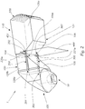
- Figure 1 shows a lighting device 1 for a motor vehicle headlight for generating a light distribution with a cut-off.
- the lighting device 1 comprises at least one light source 10, which for example comprises one or more LEDs, and an optical body 110 in which light from the at least one light source 10 can propagate.
- the optic body 110 consists of a translucent body 100 which is formed in one piece with a light feed element 101 for feeding in light which the at least one light source 10 emits and in one piece with a projection device 500.
- the optical body 110 is preferably a solid body, that is to say a body which has no through openings or opening inclusions.
- the transparent, translucent material from which the body 110 is formed has one Refractive index greater than that of air.
- the material contains, for example, PMMA (polymethyl methacrylate) or PC (polycarbonate) and is particularly preferably formed therefrom.
- the body 110 can also be made from glass material, in particular inorganic glass material.
- the optic body 110 specifically the translucent body 100, has a diaphragm device 103 with a diaphragm edge region 104, the diaphragm device 103 being arranged between the light feed element 101 and the projection device 500.
- the projection device 500 is designed to be inverting, as was already discussed at the beginning.
- the diaphragm device 103 is formed, for example, by two boundary surfaces 105, 106 of the translucent body 100, which converge in the diaphragm edge region 104, in particular into a common diaphragm edge 104a.
- Light from the at least one light source 10 is fed via the light feed element 101 into the translucent body 100, which propagates in the translucent body 100 as the first light bundle S1.
- the light feed element 101 which is designed, for example, as a collimator, is designed in such a way that it bundles the light from the at least one light source mainly in the diaphragm edge region 104.
- the diaphragm edge region 104 lies in a focal point or in a focal surface BF of the projection device 500.
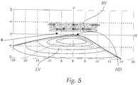
- the first light bundle S1 is modified by the diaphragm device 103 to a modified, second light bundle S2 such that this second light bundle S2 is imaged by the projection device 500 as a light distribution LV with a light-dark boundary HD (see Figure 5 , which shows an exemplary light distribution).
- the light-dark boundary HD in particular the shape and position of the light-dark boundary HD, is determined by the diaphragm edge region 104, in particular the diaphragm edge 104a of the diaphragm device 103 certainly.
- the exemplary light distribution LV shown is a classic apron distribution.
- optical axis X Below the optical axis X is the optical axis of the optic body 110, e.g. to understand the center line of the optic body 110 in relation to the apex of the exit lens or projection device.
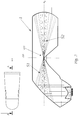
- Figure 2 shows a lighting device 1, which is essentially identical to that Figure 1 is.
- the embodiment according to Figure 2 differs from that Figure 1 only in that a screen 400 is provided between the two surfaces 105, 106. Frequently, it cannot be avoided that light also strikes the boundary surface 105. This light can typically lead to undesired scattered light, which can be intercepted with this diaphragm 400.
- this screen can be attached as an absorbent layer on the outside of surface 105.
- At least one light guide element 200, 300 specifically in the example shown, two light guide elements 200, 300 (the second light guide element 300 is in the view from Figure 1 however, the Figure 2 are removed) are provided on the optic body 110.
- Each of the light guide elements 200, 300 has a light guide element light coupling surface 201, 301 and a light guide element light coupling surface 202, 302.
- the light guide elements 200, 300 are arranged on the optical body 110 in such a way that light S3 from the light feed element 101 via the light guide element light coupling surface 201 , 301 is fed into the light-guiding elements 200, 300, as is shown in the vertical section plane BB according to Figure 4 is shown (the position of the section plane BB is in the small picture of the Figure 4 , which shows a view of the optic body from above, recognizable), propagates in it (light rays S4), in particular at least partially by means of total reflection, and re-enters the optic body 110 via the light-guiding element light decoupling surfaces 202, 302 (light rays S5).
- the light-guiding element light decoupling surfaces 202, 302 open into the optic body 110 such that they are at least partially, preferably completely below the diaphragm edge region 104, viewed in the vertical direction Z, in particular below the diaphragm edge 104a and / or below the X, Y plane.
- An upper edge 220a, 221a of the light-guiding element light decoupling surface 202, 302 is preferably at the same height as the diaphragm edge region 104 or the diaphragm edge 104a or, as shown in the figures, is preferably below.
- the light-guiding elements 200, 300 viewed in the direction of the optical axis X of the optical body 110, each extend at least up to the diaphragm edge region 104 or the diaphragm edge 104a or beyond.
- the light beams S5 originating from the light guide elements 200, 300 are finally projected by the projection device as a signlight light bundle SL into an area B of the light distribution above the light-dark boundary, and, for example as a signlight light distribution SV, are imaged in the light image.
- No light is available through the diaphragm edge area 104 or the diaphragm device 103 in a lighting device according to the prior art, which light could be imaged as a signlight in an area above the H-H line.
- the invention makes it possible to guide light from the light feed-in area 101 with the light-guiding elements 200, 300 below the diaphragm edge area past the projection device 500. After these light beams S5 originate from an area of the focal plane of the projection device, which is substantially or completely below the X, Y plane, due to the position of the light-guiding element light coupling-out surfaces 201, 301, this light S5 is transmitted from the inverting projection device 500 into an area pictured above the HH line.
- Optic body 110 and light-guiding elements 200, 300 are preferably formed in one piece with one another, and in particular from the same material.
- Such an embodiment has the advantage that at the point where the light-guiding-light coupling-out surface opens into the optic body, there is no interface at which the light from the light-guiding element could be deflected unintentionally. Light that "emerges” from the "light-guiding-element coupling-out surface” simply propagates in the optic body with the direction in which it comes from the light-guiding element.
- the light coupling-in surfaces and the light coupling-out surfaces do not represent any real surfaces, in particular no interfaces in which light is deflected.
- the light-guiding element 200 again opens into the optic body 110 in the region of the diaphragm edge 104a is widened upwards.
- This is connected with the fact that there could be a hole there with a light guide element 200 that continues to run in a straight line and through the converging surfaces 105, 106, which could be disadvantageous in terms of production technology.
- an expansion of the light guide element (s) 200 can be provided there, but this has no visual impact.
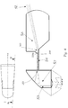
- the optic body 110 is delimited laterally opposite side delimitation surfaces 120, 121.
- Light propagating in the optic body 110 can be at least partially, preferably completely, reflected, in particular totally reflected, on the side boundary surfaces 120, 121.
- these side boundary surfaces 120, 121 are flat and diverge in the direction of the optical axis X of the optical body 110 (see small picture in FIG Figure 3 and Figure 4 ).
- the light guide elements 200, 300 are arranged on the side boundary surfaces 120, 121.
- the light-guiding elements 200, 300 are preferably configured identically and run at the same height on the optic body 110, in particular they preferably run parallel to the optical axis X.
- the light guide elements viewed in sections normal to the optical axis X, have rectangular or square cross sections.
- the two side boundary surfaces 120, 121 viewed in the direction of the optical axis X, are each divided into a rear boundary surface 120a, a central boundary surface 120b and a front boundary surface 120c, the central boundary surface 120b of each of the two side boundary surfaces 120, 121 in the horizontal direction Y, transversely springing back to the optical axis X opposite the rear and front boundary surface 120a, 120c, the respective side boundary surface 120, 121, that is to say recessed.
- a light guide element 200, 300 is arranged in each case on this recessed, central side delimitation surface 120b and is preferably connected to it in one piece.
- the Light-guiding element 200, 300 extends in the direction of the optical axis X from the rear region of the optic body 110 delimited by the rear side delimitation surface 120a to the front region of the optic body 110 delimited by the front side delimitation surface 120c.
- the central boundary surface 120b extends approximately in the region of the light-conducting body 100
- the rear boundary surface 120a extends, for example, at least partially over a region of the light feed element 101
- the front region 120c extends e.g. at least partially over the area of the projection device 500.
- a light-guiding element 200, 300 thus forms a type of web, which is located on the recessed boundary surface 120b of the optic body 110, and is preferably formed in one piece with it.
- each light-guiding element 200, 300 lies at the same height as the rear and front boundary surface 120a, 120c of the side boundary surface 120, 121 on which it is arranged.
- Total reflection preferably occurs on the lateral, outer surface 200a, a top side 200b and a bottom side 200c of each light guide element 200, 300.
- Light can enter the light-guiding body, since there the light-guiding elements 200, 300 preferably directly adjoin the light-guiding body 100 or optic body 110, in particular formed integrally therewith from the same material, this light is intercepted by the diaphragm edge device 103 in the optic body.
- light travels straight through a light guide element as it enters the light guide element or it is totally reflected at boundary surfaces 200a, 200b, 200c, which limit the light guide element to the outside, and propagates in this way to the projection device 500.
- the projection device 500 is designed to be inverting in the vertical direction.
- the projection device 500 is further configured such that, viewed in the vertical direction, light rays emanating from the same point in the intermediate light image (ie an image in the (preferably vertical, normal, normal to the optical axis X) focal plane of the projection device 200, in which preferably in about the aperture edge 104a), but propagate in different directions, are projected vertically at the same height in the photograph by the projection device.
- Such an influence is preferably not provided in the horizontal direction, so that light which emerges from the projection device 500 is generally deflected horizontally (depending on the direction of propagation before the exit).
- the projection device 500 is e.g. formed as a projection lens arrangement or includes one.
- the projection device 500 in the example shown comprises an interface (or it consists of such an interface) which limits the optics body 110 to the front, and via which interface the light propagating in the optics body, in particular the light beams S5, as a light distribution in an area are imaged in front of the optic body 110.
- the latter is shaped accordingly, in particular curved.
- the interface is preferably configured convex. In the example shown, the interface is convexly curved in vertical sections, while in horizontal sections it runs straight parallel to the optical axis.
- an outer surface of the projection device 500 is formed by a groove-shaped structure in the smooth base surface, as shown in FIG Figure 1 is indicated, the grooves forming the groove-shaped structure running in a substantially vertical direction, and preferably two grooves lying next to each other in the horizontal direction by a, in particular essentially vertical, elevation which preferably extends over the entire vertical extent of the grooves, are separated.
- the Signlight area can be specifically broadened in the horizontal direction.
- the projection device 500 is a projection lens in the form of a cylindrical lens, ie the interface of the optical body which acts as a projection lens has the shape of part of a jacket of a cylinder, with the height of the cylinder running parallel to the Y axis. For example, the height of this cylinder lies in the X, Z plane.
- the projection lens in cuts in planes parallel to the X, Z plane, the projection lens has identical cutting lines (contours).
- the design according to Figure 2 differs from that Figure 1 only by the diaphragm 400, the diaphragm 400 being modified for the invention in that it has a recess 401 for each light-guiding element 200, 300, through which the light-guiding element 200, 300 is guided.
- the Signlight light bundle SL ( Figure 4 ) is projected into an area B of the light distribution above the light-dark boundary, and, for example as a signlight light distribution SV, is imaged in the light image ( Figure 5 ).
- the area B in which the entrance light bundle S4 or parts thereof are projected, extends in the light image in the vertical direction over a range of approximately 1 ° -6 °, preferably as shown over a range of 1.5 ° - 4.5 ° above the HH line.
- area B typically extends over a range of approximately -10 ° to + 10 °, preferably over -8 ° to + 8 °.
Landscapes
- Engineering & Computer Science (AREA)
- General Engineering & Computer Science (AREA)
- Physics & Mathematics (AREA)
- Microelectronics & Electronic Packaging (AREA)
- Optics & Photonics (AREA)
- Non-Portable Lighting Devices Or Systems Thereof (AREA)
- Optical Elements Other Than Lenses (AREA)
- Lenses (AREA)
Priority Applications (7)
| Application Number | Priority Date | Filing Date | Title |
|---|---|---|---|
| EP18215157.1A EP3671016A1 (de) | 2018-12-21 | 2018-12-21 | Beleuchtungsvorrichtung für einen kraftfahrzeugscheinwerfer sowie kraftfahrzeugscheinwerfer |
| EP19816222.4A EP3899358B1 (de) | 2018-12-21 | 2019-11-26 | Beleuchtungsvorrichtung für einen kraftfahrzeugscheinwerfer sowie kraftfahrzeugscheinwerfer |
| PCT/EP2019/082583 WO2020126350A1 (de) | 2018-12-21 | 2019-11-26 | Beleuchtungsvorrichtung für einen kraftfahrzeugscheinwerfer sowie kraftfahrzeugscheinwerfer |
| CN201980085298.1A CN113195969B (zh) | 2018-12-21 | 2019-11-26 | 用于机动车前照灯的照明设备以及机动车前照灯 |
| US17/415,826 US11371669B2 (en) | 2018-12-21 | 2019-11-26 | Lighting device for a motor vehicle headlight and motor vehicle headlight |
| KR1020217019769A KR102561884B1 (ko) | 2018-12-21 | 2019-11-26 | 자동차 헤드램프용 조명 장치와 자동차 헤드램프 |
| JP2021535972A JP7258150B2 (ja) | 2018-12-21 | 2019-11-26 | 自動車前照灯用照明装置及び自動車前照灯 |
Applications Claiming Priority (1)
| Application Number | Priority Date | Filing Date | Title |
|---|---|---|---|
| EP18215157.1A EP3671016A1 (de) | 2018-12-21 | 2018-12-21 | Beleuchtungsvorrichtung für einen kraftfahrzeugscheinwerfer sowie kraftfahrzeugscheinwerfer |
Publications (1)
| Publication Number | Publication Date |
|---|---|
| EP3671016A1 true EP3671016A1 (de) | 2020-06-24 |
Family
ID=64755427
Family Applications (2)
| Application Number | Title | Priority Date | Filing Date |
|---|---|---|---|
| EP18215157.1A Withdrawn EP3671016A1 (de) | 2018-12-21 | 2018-12-21 | Beleuchtungsvorrichtung für einen kraftfahrzeugscheinwerfer sowie kraftfahrzeugscheinwerfer |
| EP19816222.4A Active EP3899358B1 (de) | 2018-12-21 | 2019-11-26 | Beleuchtungsvorrichtung für einen kraftfahrzeugscheinwerfer sowie kraftfahrzeugscheinwerfer |
Family Applications After (1)
| Application Number | Title | Priority Date | Filing Date |
|---|---|---|---|
| EP19816222.4A Active EP3899358B1 (de) | 2018-12-21 | 2019-11-26 | Beleuchtungsvorrichtung für einen kraftfahrzeugscheinwerfer sowie kraftfahrzeugscheinwerfer |
Country Status (6)
| Country | Link |
|---|---|
| US (1) | US11371669B2 (zh) |
| EP (2) | EP3671016A1 (zh) |
| JP (1) | JP7258150B2 (zh) |
| KR (1) | KR102561884B1 (zh) |
| CN (1) | CN113195969B (zh) |
| WO (1) | WO2020126350A1 (zh) |
Families Citing this family (3)
| Publication number | Priority date | Publication date | Assignee | Title |
|---|---|---|---|---|
| JP2021144902A (ja) * | 2020-03-13 | 2021-09-24 | オムロン株式会社 | 導光部材、照明装置および表示装置 |
| WO2022044078A1 (ja) * | 2020-08-24 | 2022-03-03 | 三菱電機株式会社 | 前照灯モジュール及び前照灯装置 |
| KR102602255B1 (ko) * | 2021-09-13 | 2023-11-16 | 현대모비스 주식회사 | 차량용 램프 및 그 램프를 포함하는 차량 |
Citations (6)
| Publication number | Priority date | Publication date | Assignee | Title |
|---|---|---|---|---|
| DE102008015510A1 (de) * | 2007-03-29 | 2008-10-02 | Koito Manufacturing Co., Ltd. | Leuchteneinheit eines Fahrzeugscheinwerfers |
| EP2818792A2 (en) * | 2013-06-11 | 2014-12-31 | Stanley Electric Co., Ltd. | Vehicle lighting unit |
| JP2017084556A (ja) * | 2015-10-27 | 2017-05-18 | スタンレー電気株式会社 | レンズ体、レンズ結合体及び車両用灯具 |
| WO2017185118A1 (de) * | 2016-04-29 | 2017-11-02 | Zkw Group Gmbh | Beleuchtungseinheit für einen kraftfahrzeugscheinwerfer zum erzeugen eines lichtbündels mit hell-dunkel-grenze |
| EP3290777A1 (fr) * | 2016-09-01 | 2018-03-07 | Valeo Vision | Module optique pour éclairer des points de portique |
| EP3382263A1 (en) * | 2016-09-30 | 2018-10-03 | H.A. Automotive Systems, Inc. | Condenser for low-beam vehicle light module |
Family Cites Families (11)
| Publication number | Priority date | Publication date | Assignee | Title |
|---|---|---|---|---|
| JPH029444Y2 (zh) * | 1986-11-04 | 1990-03-08 | ||
| CN100456505C (zh) * | 2006-04-10 | 2009-01-28 | 中强光电股份有限公司 | 发光模块 |
| JP2010170836A (ja) | 2009-01-22 | 2010-08-05 | Stanley Electric Co Ltd | プロジェクタ型車両用前照灯 |
| DE102012220457B4 (de) * | 2012-11-09 | 2023-05-25 | Plastic Omnium Lighting Systems Gmbh | Beleuchtungseinrichtung |
| AT518109B1 (de) * | 2016-01-14 | 2017-11-15 | Zkw Group Gmbh | Beleuchtungseinheit für einen Kraftfahrzeugscheinwerfer zum Erzeugen eines Lichtbündels mit Hell-Dunkel-Grenze |
| JP6941927B2 (ja) * | 2016-09-28 | 2021-09-29 | マクセルフロンティア株式会社 | 車両用前照灯装置 |
| US10288248B1 (en) * | 2017-12-14 | 2019-05-14 | Valeo North America, Inc. | Device for automotive lighting |
| CN207817249U (zh) * | 2018-02-28 | 2018-09-04 | 法雷奥市光(中国)车灯有限公司 | 用于车灯的光导部件、用于机动车辆的车灯和机动车辆 |
| DE102018108567A1 (de) * | 2018-04-11 | 2019-10-17 | HELLA GmbH & Co. KGaA | Scheinwerfer für Fahrzeuge |
| CN108758547A (zh) * | 2018-08-28 | 2018-11-06 | 江阴司达光电科技有限公司 | 一种汽车led前大灯 |
| FR3086734B1 (fr) * | 2018-09-28 | 2022-06-24 | Valeo Vision | Module lumineux de vehicule comprenant un pion de referencement avec une partie souple et une partie rigide |
-
2018
- 2018-12-21 EP EP18215157.1A patent/EP3671016A1/de not_active Withdrawn
-
2019
- 2019-11-26 CN CN201980085298.1A patent/CN113195969B/zh active Active
- 2019-11-26 JP JP2021535972A patent/JP7258150B2/ja active Active
- 2019-11-26 US US17/415,826 patent/US11371669B2/en active Active
- 2019-11-26 KR KR1020217019769A patent/KR102561884B1/ko active IP Right Grant
- 2019-11-26 EP EP19816222.4A patent/EP3899358B1/de active Active
- 2019-11-26 WO PCT/EP2019/082583 patent/WO2020126350A1/de unknown
Patent Citations (6)
| Publication number | Priority date | Publication date | Assignee | Title |
|---|---|---|---|---|
| DE102008015510A1 (de) * | 2007-03-29 | 2008-10-02 | Koito Manufacturing Co., Ltd. | Leuchteneinheit eines Fahrzeugscheinwerfers |
| EP2818792A2 (en) * | 2013-06-11 | 2014-12-31 | Stanley Electric Co., Ltd. | Vehicle lighting unit |
| JP2017084556A (ja) * | 2015-10-27 | 2017-05-18 | スタンレー電気株式会社 | レンズ体、レンズ結合体及び車両用灯具 |
| WO2017185118A1 (de) * | 2016-04-29 | 2017-11-02 | Zkw Group Gmbh | Beleuchtungseinheit für einen kraftfahrzeugscheinwerfer zum erzeugen eines lichtbündels mit hell-dunkel-grenze |
| EP3290777A1 (fr) * | 2016-09-01 | 2018-03-07 | Valeo Vision | Module optique pour éclairer des points de portique |
| EP3382263A1 (en) * | 2016-09-30 | 2018-10-03 | H.A. Automotive Systems, Inc. | Condenser for low-beam vehicle light module |
Also Published As
| Publication number | Publication date |
|---|---|
| EP3899358B1 (de) | 2023-03-15 |
| US11371669B2 (en) | 2022-06-28 |
| CN113195969B (zh) | 2024-02-27 |
| CN113195969A (zh) | 2021-07-30 |
| KR20210094622A (ko) | 2021-07-29 |
| EP3899358A1 (de) | 2021-10-27 |
| WO2020126350A1 (de) | 2020-06-25 |
| JP7258150B2 (ja) | 2023-04-14 |
| JP2022515178A (ja) | 2022-02-17 |
| KR102561884B1 (ko) | 2023-08-01 |
| US20220136670A1 (en) | 2022-05-05 |
Similar Documents
| Publication | Publication Date | Title |
|---|---|---|
| EP3449178B1 (de) | Beleuchtungseinheit für einen kraftfahrzeugscheinwerfer zum erzeugen eines lichtbündels mit hell-dunkel-grenze | |
| EP2799761B1 (de) | Lichtmodul für einen kraftfahrzeugscheinwerfer | |
| AT515864B1 (de) | Beleuchtungsvorrichtung für Fahrzeuge sowie Kraftfahrzeugscheinwerfer | |
| EP3899358B1 (de) | Beleuchtungsvorrichtung für einen kraftfahrzeugscheinwerfer sowie kraftfahrzeugscheinwerfer | |
| DE102012213845A1 (de) | Lichtleitelement und Lichtmodul | |
| DE102011055429B4 (de) | Beleuchtungsvorrichtung für Fahrzeuge | |
| EP3063463A1 (de) | Beleuchtungsvorrichtung für einen kraftfahrzeugscheinwerfer | |
| EP2618045A1 (de) | Beleuchtungseinrichtung für ein Kraftfahrzeug | |
| EP3653926B1 (de) | Beleuchtungsvorrichtung für einen kraftfahrzeugscheinwerfer sowie kraftfahrzeugscheinwerfer | |
| WO2014180813A1 (de) | Beleuchtungsvorrichtung für fahrzeuge | |
| EP3899353B1 (de) | Beleuchtungsvorrichtung für einen kraftfahrzeugscheinwerfer und kraftfahrzeugscheinwerfer | |
| EP3861242B1 (de) | Beleuchtungsvorrichtung für einen kraftfahrzeugscheinwerfer | |
| EP1832902A1 (de) | Flache Leuchtvorrichtung | |
| EP2963334B1 (de) | Lichtleiter-anordnung zum einsatz in einer beleuchtungseinrichtung eines kraftfahrzeugs und kraftfahrzeugbeleuchtungseinrichtung mit einer solchen lichtleiter-anordnung | |
| EP3812653B1 (de) | Signalleuchte mit einem lichtleiter | |
| DE102015204735B4 (de) | Lichtleiterelement einer Kraftfahrzeug-Beleuchtungseinrichtung und Kraftfahrzeug-Beleuchtungseinrichtung mit einem solchen Lichtleiterelement | |
| DE112019004405T5 (de) | Optisches Element einer Fahrzeugleuchte, Fahrzeugleuchtenmodul, Fahrzeug-Scheinwerfer und Fahrzeug | |
| EP3341648B1 (de) | Optisches element | |
| EP3461687A1 (de) | Lichtleiteranordnung einer kraftfahrzeugleuchte und kraftfahrzeugleuchte mit einer solchen lichtleiteranordnung | |
| DE102019211799B4 (de) | Vorrichtung zum Erzeugen einer Lichtverteilung für ein Fahrzeug | |
| DE102015207960A1 (de) | Plattenförmiges Lichtleiterelement zum Einsatz in einer Beleuchtungseinrichtung eines Kraftfahrzeugs und Beleuchtungseinrichtung mit einem solchen Lichtleiterelement | |
| EP3667389B1 (de) | Beleuchtungsvorrichtung für ein kraftfahrzeug | |
| EP2951057B1 (de) | Fahrzeuginnenleuchte | |
| EP4015897A1 (de) | Signalleuchtvorrichtung oder beleuchtungsvorrichtung für einen kraftfahrzeugscheinwerfer | |
| DE102020104678A1 (de) | Beleuchtungseinrichtung mit einem langgestreckten Lichtleiter und optimierter Lichteinkopplung |
Legal Events
| Date | Code | Title | Description |
|---|---|---|---|
| PUAI | Public reference made under article 153(3) epc to a published international application that has entered the european phase |
Free format text: ORIGINAL CODE: 0009012 |
|
| STAA | Information on the status of an ep patent application or granted ep patent |
Free format text: STATUS: THE APPLICATION HAS BEEN PUBLISHED |
|
| AK | Designated contracting states |
Kind code of ref document: A1 Designated state(s): AL AT BE BG CH CY CZ DE DK EE ES FI FR GB GR HR HU IE IS IT LI LT LU LV MC MK MT NL NO PL PT RO RS SE SI SK SM TR |
|
| AX | Request for extension of the european patent |
Extension state: BA ME |
|
| STAA | Information on the status of an ep patent application or granted ep patent |
Free format text: STATUS: THE APPLICATION IS DEEMED TO BE WITHDRAWN |
|
| 18D | Application deemed to be withdrawn |
Effective date: 20210112 |