EP3670117B1 - Kanalstruktur für einen applikationsroboter und applikationsroboter - Google Patents
Kanalstruktur für einen applikationsroboter und applikationsroboter Download PDFInfo
- Publication number
- EP3670117B1 EP3670117B1 EP19211645.7A EP19211645A EP3670117B1 EP 3670117 B1 EP3670117 B1 EP 3670117B1 EP 19211645 A EP19211645 A EP 19211645A EP 3670117 B1 EP3670117 B1 EP 3670117B1
- Authority
- EP
- European Patent Office
- Prior art keywords
- channel
- line
- robot
- channel structure
- lines
- Prior art date
- Legal status (The legal status is an assumption and is not a legal conclusion. Google has not performed a legal analysis and makes no representation as to the accuracy of the status listed.)
- Active
Links
Images




Classifications
-
- B—PERFORMING OPERATIONS; TRANSPORTING
- B25—HAND TOOLS; PORTABLE POWER-DRIVEN TOOLS; MANIPULATORS
- B25J—MANIPULATORS; CHAMBERS PROVIDED WITH MANIPULATION DEVICES
- B25J19/00—Accessories fitted to manipulators, e.g. for monitoring, for viewing; Safety devices combined with or specially adapted for use in connection with manipulators
- B25J19/0025—Means for supplying energy to the end effector
- B25J19/0029—Means for supplying energy to the end effector arranged within the different robot elements
-
- B—PERFORMING OPERATIONS; TRANSPORTING
- B05—SPRAYING OR ATOMISING IN GENERAL; APPLYING FLUENT MATERIALS TO SURFACES, IN GENERAL
- B05B—SPRAYING APPARATUS; ATOMISING APPARATUS; NOZZLES
- B05B13/00—Machines or plants for applying liquids or other fluent materials to surfaces of objects or other work by spraying, not covered by groups B05B1/00 - B05B11/00
- B05B13/02—Means for supporting work; Arrangement or mounting of spray heads; Adaptation or arrangement of means for feeding work
- B05B13/04—Means for supporting work; Arrangement or mounting of spray heads; Adaptation or arrangement of means for feeding work the spray heads being moved during spraying operation
- B05B13/0431—Means for supporting work; Arrangement or mounting of spray heads; Adaptation or arrangement of means for feeding work the spray heads being moved during spraying operation with spray heads moved by robots or articulated arms, e.g. for applying liquid or other fluent material to three-dimensional [3D] surfaces
- B05B13/0433—Means for supporting work; Arrangement or mounting of spray heads; Adaptation or arrangement of means for feeding work the spray heads being moved during spraying operation with spray heads moved by robots or articulated arms, e.g. for applying liquid or other fluent material to three-dimensional [3D] surfaces the work being vehicle components, e.g. vehicle bodies
-
- B—PERFORMING OPERATIONS; TRANSPORTING
- B25—HAND TOOLS; PORTABLE POWER-DRIVEN TOOLS; MANIPULATORS
- B25J—MANIPULATORS; CHAMBERS PROVIDED WITH MANIPULATION DEVICES
- B25J11/00—Manipulators not otherwise provided for
- B25J11/0075—Manipulators for painting or coating
-
- B—PERFORMING OPERATIONS; TRANSPORTING
- B25—HAND TOOLS; PORTABLE POWER-DRIVEN TOOLS; MANIPULATORS
- B25J—MANIPULATORS; CHAMBERS PROVIDED WITH MANIPULATION DEVICES
- B25J19/00—Accessories fitted to manipulators, e.g. for monitoring, for viewing; Safety devices combined with or specially adapted for use in connection with manipulators
- B25J19/007—Means or methods for designing or fabricating manipulators
-
- B—PERFORMING OPERATIONS; TRANSPORTING
- B05—SPRAYING OR ATOMISING IN GENERAL; APPLYING FLUENT MATERIALS TO SURFACES, IN GENERAL
- B05B—SPRAYING APPARATUS; ATOMISING APPARATUS; NOZZLES
- B05B12/00—Arrangements for controlling delivery; Arrangements for controlling the spray area
- B05B12/14—Arrangements for controlling delivery; Arrangements for controlling the spray area for supplying a selected one of a plurality of liquids or other fluent materials or several in selected proportions to a spray apparatus, e.g. to a single spray outlet
- B05B12/149—Arrangements for controlling delivery; Arrangements for controlling the spray area for supplying a selected one of a plurality of liquids or other fluent materials or several in selected proportions to a spray apparatus, e.g. to a single spray outlet characterised by colour change manifolds or valves therefor
-
- B—PERFORMING OPERATIONS; TRANSPORTING
- B05—SPRAYING OR ATOMISING IN GENERAL; APPLYING FLUENT MATERIALS TO SURFACES, IN GENERAL
- B05B—SPRAYING APPARATUS; ATOMISING APPARATUS; NOZZLES
- B05B15/00—Details of spraying plant or spraying apparatus not otherwise provided for; Accessories
- B05B15/60—Arrangements for mounting, supporting or holding spraying apparatus
- B05B15/65—Mounting arrangements for fluid connection of the spraying apparatus or its outlets to flow conduits
-
- B—PERFORMING OPERATIONS; TRANSPORTING
- B05—SPRAYING OR ATOMISING IN GENERAL; APPLYING FLUENT MATERIALS TO SURFACES, IN GENERAL
- B05B—SPRAYING APPARATUS; ATOMISING APPARATUS; NOZZLES
- B05B9/00—Spraying apparatus for discharge of liquids or other fluent material, without essentially mixing with gas or vapour
- B05B9/03—Spraying apparatus for discharge of liquids or other fluent material, without essentially mixing with gas or vapour characterised by means for supplying liquid or other fluent material
Definitions
- the invention relates to a channel structure for use in a robot for coating objects, which has a robot part with an operating space through which fluid lines are routed, with which various media are routed to an application device carried by the robot.
- the invention also relates to a robot for coating objects, which has a robot part with an operating space through which fluid lines are routed, with which various media are routed to an application device carried by the robot.
- Such robots are used in particular in paint shops for painting vehicle bodies, but also for other coatings, including other objects.
- the usually multi-axis robot guides the application device, in particular a spray gun or a high-speed rotary atomizer, and can precisely follow the contour of the object to be coated due to its multi-axis configuration.
- Operating units which are necessary for the operation of the application device, are usually attached in the vicinity of the application device on or in an arm section of the multi-axis robot. Irrespective of the operating principle of the application device, such equipment includes, among other things, paint delivery pumps, compressed air controls, reservoirs for cleaning agents and the like.
- the application device often works according to the electrostatic principle.
- the coating material is applied using a high-voltage electrode ionized and applied to the object to be coated due to electrostatic forces. This is grounded for this purpose or at least kept at approximately ground potential.
- the operating units in this case also include the electronic parts and components necessary for the electrostatic working principle.
- the application device is supplied with the required media via fluid lines, which are usually laid more or less loosely as a bundle of lines.
- fluid lines and operating units or other components of the robot share the operating area. Overall, the movements of the robot can cause mechanical stress on the fluid lines, which can lead to leakage. Replacing a defective fluid line is difficult due to the cramped spatial conditions on or in the robot and the components installed next to the fluid lines.
- JP 2007 190629 A and JP 3 830488 B2 represent the state of the art.
- the guide structure provides a motion-secured guide for a plurality of fluid lines in relation to the robot part, so that an inherent movement of the fluid lines relative to the robot part can be largely prevented there.
- the line structure For a medium in a fluid line, the line structure provides a flow path that is secured against movement in relation to the robot part.
- Either the existing fluid lines are threaded through a channel line, or a channel line itself serves as a flow path for a medium.
- the input end and the output end of the flow channel line are each designed as a connection for a fluid line feed section and a fluid line discharge section of a fluid line, so that the flow channel line can be integrated as a flow section in the fluid line.
- An advantageous variance in the line routing is achieved if one or more duct lines of the guide structure and/or the line structure have a curved course and/or have a duct fork and/or have a changing cross-section and/or a changing wall thickness in the direction of the course and/or or that a plurality of channel lines of the guide structure and/or the line structure have cross sections and/or wall thicknesses that differ from one another in the direction of travel.
- At least one holding device is provided for an operating unit, in particular for a dosing unit or for a media changing unit, and/or for a functional unit, in particular for a temperature sensor for monitoring the temperature of a medium, for a temperature control device for temperature control of a medium, for a pressure sensor for checking the pressure of a medium, for a data store, for an energy store, for an energy transmitter, for a data transmitter or a data receiver.
- a supporting structure with a frame construction is preferably provided, which is connected to the duct lines in a supporting manner.
- the frame construction preferably comprises a transverse cheek at the input end and/or a transverse cheek at the output end of the existing ducts, which runs transversely to these ducts.
- Stability also contributes if a cross beam is connected to one another at the input end and at the output end by means of longitudinal profiles.
- a transverse profile is preferably also present, which is connected at least at one end to a longitudinal profile.
- the support structure includes one or more reinforcement elements if the frame construction as such is not sufficiently rigid.
- the reinforcement elements are preferably designed as longitudinal ribs and/or cross braces and/or transverse braces.
- the frame construction and/or reinforcement elements include material recesses or material-free areas.
- the channel structure is produced at least partially from metal, plastic and/or composite materials using an additive manufacturing process.
- one or more functional units are produced as an additive partial process in the additive manufacturing process and are integrated into the channel structure.
- the support structure or the channel structure is a one-piece integrative component.
- the channel structure can advantageously be provided in or on an arm part of a robot arm.
- the arm part is that arm part of the robot that is connected to a handpiece of the robot arm, which in turn carries the application device.
- the operating space is preferably an interior space that can be closed by a cover.
- the cover can be formed by the channel structure.
- the Figures 1 to 4 show an arm section 10 with a terminal handpiece 12 of a movable robot arm 14, which is part of a multi-axis application robot 16, which is of no further interest here, as is frequently used in painting systems, the Figures 1 and 2 Illustrates a structure of a robot arm 14 as is provided in robots 16 known on the market.
- the application robot 16 carries an application device 18. This is carried by the handpiece 12 in a manner known per se and, in the present exemplary embodiment, works according to the principle of electrostatic coating.
- the application device 18 is connected to a high-voltage generator, which is not specifically shown here, as is known per se.
- the application device 18 is a high-speed rotary atomizer.
- a front arm portion 20 movably connected to the handpiece 12 and a rear arm portion 22 are shown.
- the rear arm portion 22 is in turn movably connected to the front arm portion 20 .
- articulation/gear units 24, each designated 24, are provided, as are known per se.
- the front arm part 20 defines an operating space 26 in the form of an interior space 26, which in the Figures 1 to 4 and 10 can be seen and which is accessible via an access 28 from the outside.
- the operating room 26 can also be an open area without a separate housing.
- the access 28 is closed by a cover 30 in the Figures 1 to 4 is illustrated as a folding mechanism.
- the front arm portion 20 exemplifies a general robotic portion 32 that provides an interior space 26 that conforms to the discussion below.
- a corresponding interior space 26 can also be present in other areas and other parts of the robot 16 .
- a large number of media-carrying fluid lines 34 and operating units 36 for supplying the application device 18 are accommodated in the interior space 26 of the arm part 20 .
- various media which are denoted overall by 38, such as, for example, coating materials, in particular paints, solvents and compressed air, are guided to the application device 18.
- a path through the robot 16 is illustrated by a dashed line 40 and is intended to make it clear that fluid lines 34 are also routed through the robot 16 or the robot arm 14 in other areas.
- the fluid lines 34 can also be partially routed along the outside of the robot 16 .
- the media 38 mentioned above are delivered to the application device 18 by the operating units 36 which are connected to the fluid lines 34 .
- Such operating units 36 can, for example, be dosing units 42 , in particular in the form of piston dosing devices 44 .
- Operating units 36 also include media change units, for example.
- the fluid lines 34 run in known robots 16, such as Figures 1 and 2 illustrate, more or less loosely as a bundle of lines through the interior 26 of the arm part 20. During the movements that the robot arm 14 performs during the coating processes, the fluid lines 34 also move in the interior 26 and are in this way not inconsiderably mechanically stressed. In addition, the fluid lines 34 can touch the other parts and components, in particular the operating units 36, which are arranged in the interior 26, so that the fluid lines 34 rub against these components when the robot 16 moves, thereby reducing the mechanical load on the fluid lines 34 is further increased in this area.
- the channel structure 46 designed as a separate component is provided.
- the channel structure 46 comprises a guide structure 48 for one or more fluid lines 34 and/or a line structure 50 for media 38 guided in one or more fluid lines 34.
- the guide structure 48 provides a motion-secured guide in the interior space 26 in relation to the robot part 32, so that there a movement of the fluid line 34 relative to the robot part 32, i.e. in the present case to the front arm part 20, is largely prevented.
- the line structure 50 For a medium 38 in a fluid line 34 , the line structure 50 provides a flow path in the interior space 26 that is secured against movement in relation to the robot part 32 . This is brought about by the fact that the line structure 50 provides a flow section 52 of a fluid line 34 located in the interior space 26 .
- the fluid line 34 is then formed by a feed section 34.1, which leads to the channel structure 46, the flow section 52 and a discharge section 34.2, which leads away from the channel structure 46.
- duct structure 46 includes a substantially rigid support structure 54 supporting a plurality of ducts 56, each defining a through-duct 60 bounded by a peripheral jacket 58 extending between an input end 62 and an output end 64 of the respective duct 56. Only a few duct lines 56 with the other components 58, 60, 62 and 64 are provided with reference symbols.
- Such a channel line 56 can on the one hand serve as a guide channel line 66 of the guide structure 48 for a fluid line 34 which can be routed through the through-channel 60 of the guide channel line 66 .
- the feed section 34.1 of a fluid line 34 is formed by the part that leads up to the channel structure 46.
- the flow section 52 is defined by the part of this fluid line 34 which extends through the guide channel line 66 and the discharge section 34.2 of the fluid line 34 is corresponding to its discharge section 34.2.
- such a channel line 56 can serve as a flow channel line 68 of the line structure 50 for a medium 38 which can flow through the passage channel 60 of the flow channel line 68 .
- the input end 62 and the output end 64 of the channel line 56 i.e. the flow channel line 68
- a flow channel line 68 thus corresponds to a channel line 56 with a connection 70 at both ends.
- connections 70 can in particular be designed as a type of hydraulic coupling, with which fluid-carrying lines can be coupled to one another in a fluid-tight manner in a manner known per se, for example in the form of plug-in or screw couplings.
- the supply sections 34.1 and the discharge sections 34.2 of the fluid lines 34 have connections that are complementary to the connections 70, which is not specifically shown.
- the channel structure 46 includes both the guide structure 48 and the line structure 50, with the terminals 70 of the existing flow channel lines 68 can be seen as free connection pieces.
- the channel structure 46 does not include any flow channel lines, only guide channel lines 66.
- Guide duct line 66 denoted by 66a has a curved course.
- Flow channel line 68 denoted by 68a provides a channel fork 72, at which two sub-branches 68a.1 and 68a.2 with a third sub-branch 68a.3 of the guide channel line 68 converge.
- two flows of a medium or of two media 38 are combined into one flow at the channel fork 72 or a flow of a medium 38 is branched into two flows at the fork 72 .
- figure 5 illustrates the first variant.
- channel lines 56 can also have cross sections and/or wall thicknesses that differ from one another in the course direction.
- the cross-section and wall thickness of an individual duct line 56 can also vary in the direction of travel.
- the support structure 54 includes one or more holding devices 74 with which operating units 36 or also other functional units 76 of the robot 16 can be attached to the channel structure 46 .
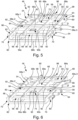
- the Figures 5 and 6 each illustrate an example of such a holding device 74, wherein figure 6 additionally shows a functional unit 76 .
- Functional units 76 can be temperature sensors, for example, with which the temperature of a medium 38 is monitored.
- a temperature control device can also be provided, with which the medium 38 is temperature-controlled, ie heated or cooled, as it flows through the channel structure 46 can be.
- a pressure sensor for checking the pressure of a medium 38 can also be provided.
- the holding devices 74 can be open or also designed as a closable housing.
- the support structure 54 also has a fastening device 78 with the aid of which the channel structure 46 can be fastened in the interior space 26 of the robot arm 14 .
- a fastening device 78 with the aid of which the channel structure 46 can be fastened in the interior space 26 of the robot arm 14 . Examples are in the Figures 5 to 8 Fastening passages 80 are shown, not all of which bear a reference number, and through which corresponding screws can be passed.
- the embodiment shown includes the channel structure 46 no guide structure, but only the line structure 50 with the flow channel lines 68, for which only a reference number is given. Instead of the curved guide duct 66a, there is a curved flow duct 68 designated 68b.
- the flow duct lines 68 can also be used as guide duct lines 66, in that a fluid line 34 to be guided through the connection 70 at the input end 62 into the duct line 56 and through the connection 70 on the Output end 64 is guided out of the duct line 56 again, without the connection function of the connections 70 being used.
- a guide structure 48 and/or a line structure 50 is present depends on the type of use of the channel structure 46. This applies to all exemplary embodiments.
- the guide structure 48 includes only a single guide channel line 66.
- the flow channel lines 68 for which again only one reference number is assigned, include both straight and curved flow channel lines, only one of which is designated 68b.
- changes in direction and branches of the duct lines 56 should follow an Archimedean spiral, so that no kinks and/or no continuous radii are produced in the duct lines 56 .
- connection 70 of the existing flow channel lines 68 protrude differently than in the Figures 5 and 6 in this exemplary embodiment, they do not protrude outwards beyond the support structure 54, but are flush with it.
- the channel structure 46 otherwise comprises no guide structure 48 and the conduit structure 50 comprises only rectilinear flow channel conduits 68, again identified by a single reference numeral.
- the support structure 54 includes a frame structure 82 and optionally reinforcing elements 84, which are required for the overall stability, rigidity and Provide torsion resistance of the channel structure 46 as a whole if these are not sufficiently guaranteed by the frame construction 82 as such.
- the frame construction 82 is not just to be understood as a peripheral frame, but overall that structural part of the duct structure 46 which is connected to the duct lines 56 in a supporting manner.
- the frame construction 82 comprises a transverse cheek 86 at the inlet ends 62 and the outlet ends 64 of the duct lines 56, the transverse cheeks 86 running transversely to the duct lines 56. How figure 7 illustrated at the output end 64, the transverse cheeks 86 can also have an angled course. The course of the transverse cheeks 86 depends on the spatial conditions in the interior 26 and is adapted thereto, so it can also be curved or multiply angled or curved.
- transverse cheeks 86 are connected to one another with the aid of longitudinal profiles 88, the longitudinal profiles 88 on the outer sides of the channel structure 46 being denoted by 88a and 88b, respectively.
- transverse profiles 90 which are connected to one of the longitudinal profiles 88 at least at one point.
- the Figures 5 and 6 show two such transverse profiles 90a and 90b, the transverse profile 90a being connected at both ends to the longitudinal profiles 88 located there and the transverse profile 90b being connected to a longitudinal profile 88 only at one end.
- FIG 7 shows three transverse profiles 90a, which extend between the two longitudinal profiles 88a and 88b there. Two of these are each arranged near the transverse cheeks 86 and contribute to the mounting of the connections 70 of the duct lines 56 .
- transverse profiles 90c and 90d attached at one end to the longitudinal profile 88a and, starting therefrom, inclined in different directions to the longitudinal direction.
- a transverse profile 90c and a transverse profile 90d intersect in each case.
- Further transverse profiles 90e extend between the longitudinal profile 88b and an adjacent duct line 56.
- a third longitudinal profile 88c can be recognized between the longitudinal profiles 88a, 88b.
- Transverse profiles 90a extend from the longitudinal profile 88a to the longitudinal profile 88c or from the longitudinal profile 88b to the longitudinal profile 88c.
- the transverse profiles 90 in figure 8 upper region of the local channel structure 46 are arranged offset in the longitudinal direction.
- the reinforcing elements 84 are in the channel structures 46 after Figures 5 and 6 formed as longitudinal ribs 92, which extend between the transverse cheeks 86 and 90 transverse profiles.
- Reinforcement elements 84 are designed as cross braces 94 or cross braces 96 which each extend between two adjacent duct lines 56 .
- the channel structure 46 according to figure 8 does not include separate reinforcement elements; the stability of the channel structure 46 is ensured there by the frame construction 82 .
- the channel structure 46 is designed to save as much material as possible.
- the components of the frame structure 82 and the reinforcement elements 84 can include material recesses or material-free areas 94, which is shown in FIGS Figures 5 and 6 is illustrated in the respective longitudinal profile 88a.
- the support structure 54 can be designed as a lattice structure overall.
- the channel structure 46 can be produced using an additive manufacturing method, in which the channel structure 46 or at least parts thereof is built up in layers by depositing material. As is known, metals, plastics or composite materials can be used as materials for this.
- Various components and parts of the channel structure 46 can, moreover, be made of different materials--regardless of the type of production and not just in the case of additive manufacturing methods.
- the materials can be selected, for example, taking into account desired properties of a part or component, for example properties such as color, strength, electrical conductivity, chemical resistance, temperature behavior and the like.
- one or more functional units 76 mentioned above are not attached as a separate component in each case, but rather are produced in the additive manufacturing process as an additive partial process and thereby integrated into the channel structure 46 .
- Thread and coupling components of the connections 70 can also be produced additively, so that separate components can also be dispensed with with regard to the connections 70 .
- Additive manufacturing processes also allow the construction of multi-layer material composites.
- a duct line 56 can have an inner jacket with good thermal conductivity, which is surrounded by a thermally insulating outer jacket.
- the support structure 54 is designed as a one-piece integrative component. This is to be understood in such a way that there are no components that can be detached using separate fastening means are connected to each other. If the channel structure 46 is produced by an additive manufacturing method, the channel structure 46 can be integrated in one piece and possibly even include functional units 76 in an integrated manner.
- the support structure 54 or the channel structure 46 is constructed in a modular manner from a plurality of components, from which the guide structure 48 and the line structure 50 with the channel lines 56 are formed during assembly.
- Figure 8A illustrates a duct 56a shown in figure 8 is also denoted and carries a plurality of connecting members 100 which form the transverse cheeks 86 and transverse profiles 90 in the formed channel structure 46 .
- figure 8 8 also shows that the outer longitudinal profiles 88a and 88b and the central longitudinal profile 88c are also manufactured as separate components and have connecting elements 102 which are complementary to the connecting links 100.
- FIG. 8 also shows that the outer longitudinal profiles 88a and 88b and the central longitudinal profile 88c are also manufactured as separate components and have connecting elements 102 which are complementary to the connecting links 100.
- duct lines 56 designed modularly as such, which are arranged between the central longitudinal profile 90c and the outer longitudinal profile 90b; there are two channel sections 56.1 and 56.2 that can be coupled, each of which defines a line module 104.
- duct lines designated 56b and 56c, which are designed as a double-strand module.
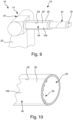
- FIG. 9 and 10 12 illustrate a variation in which the cover 30 of the interior space 26 provides the channel structure 46.
- FIG. figure 10 shows that corresponding duct lines 56 are present on the side of this cover 30 pointing into the interior space 26 . So that the channel structure 46 can also form the cover 30, the channel structure 46 defines the interior space 26 pioneering side a closed surface 106. Otherwise, the above applies to the embodiments according to Figures 5 to 8 Said accordingly.
Landscapes
- Engineering & Computer Science (AREA)
- Robotics (AREA)
- Mechanical Engineering (AREA)
- Manipulator (AREA)
- Spray Control Apparatus (AREA)
Description
- Die Erfindung betrifft eine Kanalstruktur zur Verwendung in einem Roboter zur Beschichtung von Gegenständen, welcher ein Roboterteil mit einem Betriebsraum aufweist, durch welchen Fluidleitungen geführt sind, mit denen verschiedene Medien zu einer von dem Roboter getragenen Applikationseinrichtung geführt werden.
- Außerdem betrifft die Erfindung einen Roboter zur Beschichtung von Gegenständen, welcher ein Roboterteil mit einem Betriebsraum aufweist, durch welchen Fluidleitungen geführt sind, mit denen verschiedene Medien zu einer von dem Roboter getragenen Applikationseinrichtung geführt werden.
- Derartige Roboter werden insbesondere in Lackieranlagen zum Lackieren von Fahrzeugkarosserien, aber auch zum sonstigen Beschichten auch anderer Gegenstände, eingesetzt. Der meist mehrachsige Roboter führt die Applikationseinrichtung, insbesondere eine Spritzpistole oder einen Hochrotationszerstäuber, und kann aufgrund seiner Mehrachsigkeit der Kontur des zu beschichtenden Gegenstandes genau folgen.
- Üblicherweise sind in der Nähe der Applikationseinrichtung an oder in einem Armabschnitt des mehrachsigen Roboters Betriebseinheiten angebracht, welche zum Betrieb der Applikationseinrichtung erforderlich sind. Zu solchen Betriebsmitteln zählen unter anderem unabhängig von dem Arbeitsprinzip der Applikationseinrichtung Lackförderpumpen, Druckluftsteuerungen, Reservoirs für Reinigungsmittel und dergleichen.
- Häufig arbeitet die Applikationseinrichtung nach dem elektrostatischen Prinzip. In diesem Fall wird das Beschichtungsmaterial mittels einer Hochspannungselektrode ionisiert und aufgrund elektrostatischer Kräfte auf den zu beschichtenden Gegenstand aufgebracht. Dieser ist hierfür geerdet oder zumindest auf annähernd Massepotential gehalten. Zu den Betriebseinheiten gehören in diesem Fall auch die elektronischen Bauteile und Komponenten, die für das elektrostatische Arbeitsprinzip erforderlich sind.
- Die Applikationseinrichtung wird über Fluidleitungen mit erforderlichen Medien versorgt, die meist als Leitungsbündel mehr oder weniger lose verlegt sind. Wie weiter untern nochmals erläutert wird, teilen sich Fluidleitungen und Betriebseinheiten oder weitere Komponenten des Roboters den Betriebsbereich. Insgesamt kann es durch die Bewegungen des Roboters zu mechanischen Belastungen der Fluidleitungen kommen, welche zu einer Leckage führen kann. Ein Austausch einer defekten Fluidleitung ist auf Grund der beengten räumlichen Verhältnisse am bzw. im Roboter und durch die neben den Fluidleitungen verbauten Komponenten erschwert.
- Die Dokumente
DE 60 2005 003408 T2 ,JP 2007 190629 A JP 3 830488 B2 - Es ist Aufgabe der Erfindung, eine Lösung für diese Schwierigkeiten bereitzustellen.
- Diese Aufgabe wird durch eine Kanalstruktur nach Anspruch 1 gelöst, welche
- a) als gesondertes Bauteil ausgebildet ist;
und - b) eine Führungsstruktur für mehrere Fluidleitungen umfasst; und/oder
- c) eine Leitungsstruktur für in ein oder mehreren Fluidleitungen geführte Medien umfasst.
- Die Führungsstruktur stellt für mehrere Fluidleitungen eine bezogen auf das Roboterteil bewegungsgesicherte Führung bereit, so dass dort eine Eigenbewegung der Fluidleitungen relativ zu dem Roboterteil weitgehend unterbunden werden kann.
- Die Leitungsstruktur stellt für ein Medium in einer Fluidleitung einen bezogen auf das Roboterteil bewegungsgesicherten Strömungsweg bereit.
- Insgesamt werden dadurch die bewegungsinduzierten mechanischen Belastungen für die Fluidleitungen reduziert.
- Es ist vorgesehen, dass
- a) die Führungsstruktur wenigstens eine Kanalleitung mit einem Eingangsende und einem Ausgangsende umfasst, welche einen Durchgangskanal definiert und als Führungs-Kanalleitung dient, derart, dass eine Fluidleitung durch den Durchgangskanal hindurchführbar ist; und von Vorteil, wenn
- b) die Leitungsstruktur wenigstens eine Kanalleitungen mit einem Eingangsende und einem Ausgangsende umfasst, welche einen Durchgangskanal definiert und als Strömungs-Kanalleitung der Leitungsstruktur dient, derart, dass ein Medium durch den Durchgangskanal strömen kann.
- Entweder werden also vorhandene Fluidleitungen gleichsam durch eine Kanalleitung gefädelt oder eine Kanalleitung selbst dient als Strömungsweg für ein Medium.
- In letzterem Fall ist es günstig, wenn das Eingangsende und das Ausgangsende der Strömungs-Kanalleitung jeweils als Anschluss für einen Fluidleitungs-Zuführabschnitt und einen Fluidleitungs-Abführabschnitt einer Fluidleitung ausgebildet ist, so dass die Strömungs-Kanalleitung als Strömungsabschnitt in die Fluidleitung integriert werden kann.
- Eine vorteilhafte Varianz in der Leitungsführung wird erzielt, wenn eine oder mehrere Kanalleitungen der Führungsstruktur und/oder der Leitungsstruktur einen gekrümmten Verlauf haben und/oder eine Kanalgabelung aufweisen und/oder in Verlaufsrichtung einen sich ändernden Querschnitt und/oder eine sich ändernde Wandstärke haben und/oder dass mehrere Kanalleitungen der Führungsstruktur und/oder der Leitungsstruktur in Verlaufrichtung voneinander abweichende Querschnitte und/oder Wandstärken haben.
- Für die Montage im Betriebsraum ist es außerdem günstig, wenn wenigstens eine Halteeinrichtung für eine Betriebseinheit, insbesondere für eine Dosiereinheit oder für eine Medienwechseleinheit, und/oder für eine Funktionseinheit vorgesehen ist, insbesondere für einen Temperatursensor zur Überwachung der Temperatur eines Mediums, für eine Temperiereinrichtung zum Temperieren eines Mediums, für einen Drucksensor zum Überprüfen des Druckes eines Mediums, für einen Datenspeicher, für einen Energiespeicher, für einen Energieüberträger, für einen Datensender oder einen Datenempfänger.
- Für eine stabile Ausbildung der Kanalstruktur ist vorzugsweise eine Tragstruktur mit einer Rahmenkonstruktion vorgesehen, welche tragend mit den Kanalleitungen verbunden ist.
- Die Rahmenkonstruktion umfasst bevorzugt eine Querwange an dem Eingangsende und/oder eine Querwange an dem Ausgangsende der vorhandenen Kanalleitungen umfasst, welche quer zu diesen Kanalleitungen verläuft.
- Zu Stabilität trägt außerdem bei, wenn jeweils eine Querwange am Eingangsende und am Ausgangsende mittels Längsprofilen miteinander verbunden sind. Vorzugsweise ist ferner ein Querprofil vorhanden, welches zumindest an einem Ende mit einem Längsprofil verbunden ist.
- Zudem ist es günstig, wenn die Tragstruktur ein oder mehrere Verstärkungselemente umfasst, wenn die Rahmenkonstruktion als solche nicht ausreichend starr ist.
- Die Verstärkungselemente sind bevorzugt als Längsrippen und/oder Kreuzstreben und/oder Querstreben ausgebildet.
- Um möglichst materialsparend zu arbeiten umfassen die Rahmenkonstruktion und/oder Verstärkungselemente Materialausnehmungen bzw. materialfreie Bereiche.
- Es ist besonders günstig, wenn die Kanalstruktur zumindest teilweise durch ein additives Fertigungsverfahren aus Metall, Kunststoff und/oder Verbundmaterialen hergestellt ist.
- Besonders günstig ist es dabei, wenn eine oder mehrere Funktionseinheiten bei dem additiven Fertigungsverfahren als additiver Teilvorgang hergestellt und dabei in die Kanalstruktur integriert sind.
- Von besonderem Vorteil ist es, wenn die Tragstruktur oder die Kanalstruktur ein einstückiges integratives Bauteil ist.
- Die oben genannte Aufgabe wird bei einem Roboter zur Beschichtung von Gegenständen der eingangs genannten Art dadurch gelöst, dass eine Kanalstruktur mit einigen oder allen der oben zur Kanalstruktur erläuterten Merkmale vorgesehen ist.
- Die Kanalstruktur kann vorteilhaft in oder an einem Armteil eines Roboterarmes vorgesehen sein.
- Besonders in der Nähe der Applikationseinrichtung kommen die oben erläuterten Schwierigkeiten zu tragen. Daher ist es günstig, wenn das Armteil dasjenige Armteil des Roboters ist, das mit einem Handstück des Roboterarmes verbunden ist, welches seinerseits die Applikationseinrichtung trägt.
- Bevorzugt ist der Betriebsraum ein Innenraum ist, der durch eine Abdeckung verschließbar ist.
- Dabei kann die Abdeckung durch die Kanalstruktur ausgebildet sein.
- Nachstehend werden Ausführungsbeispiele der Erfindung anhand der Zeichnungen näher erläutert. In diesen zeigen:
- Figur 1
- einen Armabschnitt eines mehrachsigen Roboters nach dem Stand der Technik, der eine Applikationseinrichtung trägt, wobei in einem von außen durch einen Zugang erreichbaren Innenraum eines Armteils des Roboters Fluidleitungen und Betriebseinheiten zur Versorgung der Applikationseinrichtung mit Medien untergebracht sind;
- Figur 2
- eine Draufsicht auf den Armabschnitt mit Blick auf die Abdeckung;
- Figur 3
- eine der
Figur 1 entsprechende Ansicht des Armabschnitts mit einer erfindungsgemäßen Kanalstruktur im Innenraum, die einer Führungsstruktur für eine oder mehrere Fluidleitungen und/oder eine Leitungsstruktur für Medien umfasst; wobei sich im Innenraum auch die Betriebseinheiten befinden; - Figur 4
- eine der
Figur 3 entsprechende Ansicht des Armabschnitts, wobei die Betriebseinheiten entfernt sind; - Figuren 5 bis 8
- verschiedene Ausführungsbeispiele der Kanalstruktur;
- Figur 9
- einen Armabschnitt einer Abwandlung eines Roboters, bei welchem die Abdeckung des Innenraums die Kanalstruktur bereitstellt;
- Figur 10
- eine perspektivische Querschnittansicht des Armteiles mit dem Zugang zum Innenraum.
- Die
Figuren 1 bis 4 zeigen einen Armabschnitt 10 mit einem endständigen Handstück 12 eines beweglichen Roboterarms 14, der Teil eines hier nicht weiter interessierenden mehrachsigen Applikationsroboters 16 ist, wie er bei Lackieranlagen häufig verwendet wird, wobei dieFiguren 1 und 2 einen Aufbau eines Roboterarms 14 illustriert, wie er bei am Markt bekannten Robotern 16 vorgesehen ist. - Der Applikationsroboter 16 trägt eine Applikationseinrichtung 18. Diese ist in an und für sich bekannter Weise von dem Handstück 12 getragen und arbeitet beim vorliegenden Ausführungsbeispiel nach dem Prinzip der elektrostatischen Beschichtung. Hierfür ist die Applikationseinrichtung 18 mit einem hier nicht eigens gezeigten Hochspannungsgenerator verbunden, wie es an und für sich bekannt ist. Die Applikationseinrichtung 18 ist beim vorliegenden Ausführungsbeispiel ein Hochrotationszerstäuber.
- Von dem Armabschnitt 10 des Roboters sind ein vorderes Armteil 20, das beweglich mit dem Handstück 12 verbunden ist, und ein hinteres Armteil 22 gezeigt. Das hintere Armteil 22 ist seinerseits beweglich mit dem vorderen Armteil 20 verbunden. Zur beweglichen Verbindung des Handstücks 12 und der Armteile 20, 22 miteinander sind jeweils mit 24 bezeichnete Gelenk-/Getriebeeinheiten 24 vorhanden, wie sie an und für sich bekannt sind.
- Das vordere Armteil 20 begrenzt einen Betriebsraum 26 in Form eines Innenraumes 26, welcher in den
Figuren 1 bis 4 und10 zu erkennen ist und welcher über einen Zugang 28 von außen erreichbar ist. Der Betriebsraum 26 kann auch ein offener Bereich ohne gesonderte Einhausung sein. - Im Betrieb des Roboters 16 ist der Zugang 28 durch eine Abdeckung 30 verschlossen, die in den
Figuren 1 bis 4 als Klappmechanismus veranschaulicht ist. Das vordere Armteil 20 dient als Beispiel allgemein eines Roboterteiles 32, welches einen Innenraum 26 bereitstellt, welcher den nachfolgenden Erläuterungen entspricht. Ein entsprechender Innenraum 26 kann auch in anderen Bereichen und anderen Teilen des Roboters 16 vorhanden sein. - In dem Innenraum 26 des Armteils 20 sind eine Vielzahl von medienführenden Fluidleitungen 34 sowie Betriebseinheiten 36 zur Versorgung der Applikationseinrichtung 18 untergebracht. Mit Hilfe der Fluidleitungen 34 werden verschiedene Medien, die insgesamt mit 38 bezeichnet sind, wie zum Beispiel Beschichtungsmaterialien, insbesondere Lacke, Lösemittel und Druckluft zur Applikationseinrichtung 18 geführt. Ein Weg durch den Roboter 16 hindurch ist durch eine gestrichelte Linie 40 veranschaulicht und soll verdeutlichen, dass Fluidleitungen 34 auch in anderen Bereichen durch den Roboter 16 bzw. den Roboterarm 14 hindurch verlegt sind. Alternativ können die Fluidleitungen 34 auch teilweise außen am Roboter 16 entlang geführt sein.
- Die oben genannten Medien 38 werden durch die Betriebseinheiten 36, die mit den Fluidleitungen 34 verbunden sind, an die Applikationseinrichtung 18 abgegeben. Solche Betriebseinheiten 36 können beispielsweise Dosiereinheiten 42, insbesondere in Form von Kolbendosierern 44 sein. Zu Betriebseinheiten 36 zählen zum Beispiel auch Medienwechseleinheiten.
- Außerdem befinden sich in dem Innenraum 26 des vorderen Armteils 20 noch Bauteile und Komponenten, die nicht eigens gezeigt sind und zum Betrieb und Bewegen des Roboters 16 bzw. des Roboterarms 14 notwendig sind. Hierbei kann es sich, wie eingangs angesprochen, beispielsweise um elektronische Bauteile, Motoren, Kabelleitungen und dergleichen handeln.
- Die Fluidleitungen 34 verlaufen bei bekannten Robotern 16, wie die
Figuren 1 und 2 veranschaulichen, mehr oder weniger lose als Leitungsbündel durch den Innenraum 26 des Armteils 20. Bei den Bewegungen, die der Roboterarm 14 bei den Beschichtungsvorgängen durchführt, bewegen sich auch die Fluidleitungen 34 in dem Innenraum 26 und werden auf diese Weise nicht unbeträchtlich mechanisch beansprucht. Darüber hinaus können die Fluidleitungen 34 die weiteren Bauteilen und Komponenten, insbesondere die Betriebseinheiten 36, die in dem Innenraum 26 angeordnet sind, berühren, so dass die Fluidleitungen 34 bei Bewegungen des Roboters 16 an diesen Bauteilen entlang reiben, wodurch die mechanische Belastung der Fluidleitungen 34 in diesem Bereich noch weiter erhöht wird. - Hierdurch kann es zu Leckagen an einer Fluidleitungen 34 in dem Innenraum 26 kommen. Um in diesem Fall eine betroffene Fluidleitung 34 auszutauschen, müssen zunächst die Betriebseinheiten 36 ausgebaut werden, um einen Zugang zu den Fluidleitungen 32 zu ermöglichen. Darüber hinaus ist es verhältnismäßig aufwendig, die defekte Fluidleitung 36 aus dem Roboter 16 und dessen Roboterarm 14 heraus- und eine neue Fluidleitung 36 in und durch den Roboter 16 bzw. dessen Roboterarm 14 hineinzuführen. Die defekte und die neue Fluidleitung 36 müssen insbesondere in dem verhältnismäßig engen und räumlich begrenzten Innenraum 26 unter Berücksichtigung der Lage vorhanden Fluidleitungen 34 sorgsam durch das vorhandene Leitungsbündel geführt werden.
- Damit diese Schwierigkeiten im Innenraum 26 gemindert werden, ist eine als gesondertes Bauteil ausgebildete Kanalstruktur 46 vorgesehen. Die Kanalstruktur 46 umfasst eine Führungsstruktur 48 für eine oder mehrere Fluidleitungen 34 und/oder eine Leitungsstruktur 50 für in ein oder mehreren Fluidleitungen 34 geführte Medien 38.
- Bei den Ausführungsbeispielen der Kanalstruktur 46 gemäß den
Figuren 5, 6 ,7 und8 sind jeweils funktionsgleiche Bauteile und Komponenten mit denselben Bezugszeichen versehen. - Die Führungsstruktur 48 stellt für eine Fluidleitung 34 eine bezogen auf das Roboterteil 32 bewegungsgesicherte Führung in dem Innenraum 26 bereit, so dass dort eine Eigenbewegung der Fluidleitung 34 relativ zu dem Roboterteil 32, d.h. vorliegend zu dem vorderen Armteil 20, weitgehend unterbunden ist.
- Die Leitungsstruktur 50 stellt für ein Medium 38 in einer Fluidleitung 34 einen bezogen auf das Roboterteil 32 bewegungsgesicherten Strömungsweg in dem Innenraum 26 bereit. Dies wird dadurch bewirkt, dass die Leitungsstruktur 50 einen im Innenraum 26 angesiedelten Strömungsabschnitt 52 einer Fluidleitung 34 bereitstellt. Die Fluidleitung 34 ist dann durch einen Zuführabschnitt 34.1, der zu der Kanalstruktur 46 führt, den Strömungsabschnitt 52 und einen Abführabschnitt 34.2, der von der Kanalstruktur 46 wegführt, ausgebildet.
- Wie die
Figuren 5, 6 ,7 und8 zeigen, umfasst die Kanalstruktur 46 eine weitgehend starre Tragstrukur 54, welche mehrere Kanalleitungen 56 lagert, die jeweils einen von einem Umfangsmantel 58 begrenzten Durchgangskanal 60 definieren, der sich zwischen einem Eingangsende 62 und einem Ausgangsende 64 der jeweiligen Kanalleitung 56 erstreckt. Es sind nur einige Kanalleitungen 56 mit den weiteren Komponenten 58, 60, 62 und 64 mit Bezugszeichen versehen. - Eine solche Kanalleitung 56 kann einerseits als Führungs-Kanalleitung 66 der Führungsstruktur 48 für eine Fluidleitung 34 dienen, die durch den Durchgangskanal 60 der Führungs-Kanalleitung 66 hindurch geführt werden kann. In diesem Fall ist der Zuführabschnitt 34.1 einer Fluidleitung 34 durch den Teil gebildet, der bis zu der Kanalstruktur 46 führt. Der Strömungsabschnitt 52 ist durch den Teil dieser Fluidleitung 34 definiert, der sich durch die Führungs-Kanalleitung 66 erstreckt und der Abführabschnitt 34.2 der Fluidleitung 34 ist entsprechend deren Abführabschnitt 34.2.
- Andererseits kann eine solche Kanalleitung 56 als Strömungs-Kanalleitung 68 der Leitungsstruktur 50 für ein Medium 38 dienen, welches durch den Durchgangskanal 60 der Strömungs-Kanalleitung 68 strömen kann. In diesem Fall sind das Eingangsende 62 und das Ausgangsende 64 der Kanalleitung 56, d.h. der Strömungs-Kanalleitung 68 als Anschlüsse 70 für Fluidleitungen 34 ausgebildet, so dass das Eingangsende 62 und das Ausgangsende 64 einer Strömungs-Kanalleitung 68 strömungstechnisch und fluiddicht mit einer Fluidleitung 34 lösbar gekoppelt werden kann. Eine Strömung-Kanalleitung 68 entspricht somit einer Kanalleitung 56 mit jeweils einem Anschluss 70 an beiden Enden. Die Anschlüsse 70 können insbesondere als eine Art Hydraulik-Kupplung ausgebildet sein, mit welcher fluidführende Leitungen in an und für sich bekannter Weise fluiddicht miteinander gekoppelt werden können, beispielsweise in Form von Steck- oder Schraubkupplungen. Die Zuführabschnitte 34.1 und die Abführabschnitte 34.2 der Fluidleitungen 34 weisen zu den Anschlüssen 70 komplementäre Anschlüsse auf, was nicht eigens gezeigt ist.
- Bei dem Ausführungsbeispiel gemäß
Figur 5 umfasst die Kanalstruktur 46 sowohl die Führungsstruktur 48 als auch die Leitungsstruktur 50, wobei die Anschlüsse 70 der vorhandenen Strömungs-Kanalleitungen 68 als freie Anschlussstutzen zu erkennen sind. - Bei einer nicht eigens gezeigten Abwandlung umfasst die Kanalstruktur 46 keine Strömungs-Kanalleitungen, sondern nur Führungs-Kanalleitungen 66.
- Eine in
Figur 5 mit 66a bezeichnete Führungs-Kanalleitung 66 weist einen gekrümmten Verlauf auf. Eine inFigur 5 mit 68a bezeichnete Strömungs-Kanalleitung 68 stellt eine Kanalgabelung 72 bereit, an welcher zwei Teilzweige 68a.1 und 68a.2 mit einem dritten Teilzweig 68a.3 der Führungs-Kanalleitung 68 zusammenlaufen. Abhängig von der Strömungsrichtung werden zwei Strömungen eines Mediums oder zweier Medien 38 an der Kanalgabelung 72 zu einer Strömung zusammengeführt oder eine Strömung eines Mediums 38 wird an der Gabelung 72 in zwei Strömungen aufgezweigt.Figur 5 veranschaulicht die erste Variante. - Abgesehen von unterschiedlichen Verläufen können verschiedene Kanalleitungen 56 in Verlaufrichtung auch voneinander abweichende Querschnitte und/oder Wandstärken haben. Der Querschnitt und die Wandstärke einer einzelnen Kanalleitung 56 können sich ebenfalls in Verlaufrichtung ändern.
- Die Tragstruktur 54 umfasst eine oder mehrere Halteeinrichtung 74, mit denen sich Betriebseinheiten 36 oder auch andere Funktionseinheiten 76 des Roboters 16 an der Kanalstruktur 46 anbringen lassen. Die
Figuren 5 und 6 veranschaulichen jeweils exemplarisch eine solche Halteeinrichtung 74, wobeiFigur 6 zusätzlich eine Funktionseinheit 76 zeigt. Funktionseinheiten 76 können beispielsweise Temperatursensoren sein, mit welchen die Temperatur eines Mediums 38 überwacht wird. Auch eine Temperiereinrichtung kann vorgesehen sein, mit welcher das Medium 38 beim Durchströmen der Kanalstruktur 46 temperiert, d.h. erwärmt oder abgekühlt werden kann. Auch ein Drucksensor zum Überprüfen des Druckes eines Mediums 38 kann vorgesehen sein. Darüber hinaus können andere elektronische Bauteile wie Datenspeicher, Energiespeicher, Energieüberträger, Datensender oder - empfänger oder dergleichen bereitgestellt werden, sofern diese für den Betrieb des Roboters 16 erforderlich sind. Die Halteeinrichtungen 74 können offen oder auch als verschließbares Gehäuse ausgebildet sein. - Die Tragstruktur 54 weist außerdem eine Befestigungseinrichtung 78 auf, mit deren Hilfe die Kanalstruktur 46 im Innenraum 26 des Roboterarms 14 befestigt werden kann. Beispielhaft sind in den
Figuren 5 bis 8 Befestigungsdurchgänge 80 gezeigt, die nicht alle ein Bezugszeichen tragen und durch welche entsprechende Schrauben geführt werden können. - Bei dem in
Figur 6 gezeigten Ausführungsbeispiel umfasst die Kanalstruktur 46 keine Führungsstruktur, sondern nur die Leitungsstruktur 50 mit den Strömungs-Kanalleitungen 68, für die nur ein Bezugszeichen angegeben ist. Anstelle der gekrümmten Führungs-Kanalleitung 66a ist dort eine mit 68b bezeichnete gekrümmte Strömungs-Kanalleitung 68 vorhanden. - Wenn der Querschnitt der Anschlüsse 70 entsprechend dimensioniert ist, können die Strömungs-Kanalleitungen 68 allerding auch als Führungs-Kanalleitungen 66 genutzt werden, indem eine zu führende Fluidleitung 34 durch den Anschluss 70 am Eingangsende 62 in die Kanalleitung 56 hinein und durch den Anschluss 70 am Ausgangsende 64 wieder aus der Kanalleitung 56 hinaus geführt wird, ohne das die Anschlussfunktion der Anschlüsse 70 genutzt wird. Ob eine Führungsstruktur 48 und/oder eine Leitungsstruktur 50 vorhanden ist, ergibt sich aus der Art der Nutzung der Kanalstruktur 46. Dies gilt für alle Ausführungsbeispiele.
- Bei dem Ausführungsbeispiel nach
Figur 7 umfasst die Führungsstruktur 48 lediglich eine einzige Führungs-Kanalleitung 66. Bei der Leitungsstruktur 50 umfassen die Strömungs-Kanalleitungen 68, für die wieder nur ein Bezugszeichen vergeben ist, neben geradlinigen auch gekrümmte Strömungs-Kanalleitungen, von denen lediglich eine mit 68b bezeichnet, ist. Grundsätzlich sollen Richtungsänderungen und Verzweigungen der Kanalleitungen 56 einer archimedischen Spirale folgen, so dass keine Knicke und/oder keine kontinuierlichen Radien bei den Kanalleitungen 56 erzeugt werden. - Die Anschlüsse 70 der vorhandenen Strömungs-Kanalleitungen 68 ragen anders als bei den
Figuren 5 und 6 bei diesem Ausführungsbeispiel nicht über die Tragstruktur 54 nach außen hervor, sondern schließen mit dieser bündig ab. Dies ist auch bei dem Ausführungsbeispiel nachFigur 8 der Fall, bei dem die Kanalstruktur 46 im Übrigen keine Führungsstruktur 48 umfasst und die Leitungsstruktur 50 nur geradlinige Strömungs-Kanalleitungen 68 aufweist, die erneut mit nur einem Bezugszeichen gekennzeichnet sind. - Neben verschiedenen Varianten der Kanalstruktur 46 bezogen auf die Führungsstruktur 48 und die Leitungsstruktur 50 veranschaulichen die
Figuren 5 bis 8 und 8A unterschiedliche Konzepte zur Ausbildung der Tragstruktur 54, welche nun erläutert werden. Wenn auf Unterschiede hingewiesen oder auf ein bestimmtes Ausführungsbeispiel Bezug genommen wird, gilt das jeweils für ein bestimmtes Ausführungsbeispiel Gesagte grundsätzlich für die Tragstruktur 54, d.h. Konstruktionsmerkmale, die anhand eines konkreten Ausführungsbeispiels erläutert werden, können ohne Weiteres auch bei einem anderen Ausführungsbeispiel als alternative oder ergänzende Konstruktionsmerkmale umgesetzt werden. - Die Tragstruktur 54 umfasst eine Rahmenkonstruktion 82 und gegebenenfalls Verstärkungselemente 84, die für die insgesamt erforderliche Stabilität, Steifheit und Verwindungsbeständigkeit der Kanalstruktur 46 insgesamt sorgen, wenn diese durch die Rahmenkonstruktion 82 als solche nicht ausreichend gewährleistet sind. Als Rahmenkonstruktion 82 ist nicht nur ein umlaufender Rahmen zu verstehen, sondern insgesamt derjenige Konstruktionsteil der Kanalstruktur 46, der tragend mit den Kanalleitungen 56 verbunden ist.
- Die Rahmenkonstruktion 82 umfasst bei den vorliegenden Ausführungsbeispielen jeweils eine Querwange 86 an den Eingangsenden 62 und den Ausgangsenden 64 der Kanalleitungen 56, wobei die Querwangen 86 quer zu den Kanalleitungen 56 verlaufen. Wie
Figur 7 am Ausgangsende 64 veranschaulicht, können die Querwangen 86 auch einen gewinkelten Verlauf haben. Der Verlauf der Querwangen 86 hängt von den räumlichen Gegebenheiten im Innenraum 26 ab und ist daran angepasst, kann also auch gekrümmt oder mehrfach gewinkelt oder gekrümmt sein. - Die Querwangen 86 sind unter Zuhilfenahme von Längsprofilen 88 miteinander verbunden, wobei die Längsprofile 88 an den Außenseiten der Kanalstruktur 46 mit 88a bzw. 88b bezeichnet sind. Zusätzlich zu den Querwangen 86 sind Querprofile 90 vorhanden, die zumindest an einer Stelle mit einem der Längsprofile 88 verbunden sind.
- Die
Figuren 5 und 6 zeigen zwei solche Querprofile 90a und 90b, wobei das Querprofil 90a an beiden Enden mit den dortigen Längsprofilen 88 und das Querprofil 90b nur an einem Ende mit einem Längsprofil 88 verbunden ist. -
Figur 7 zeigt drei Querprofile 90a, die sich zwischen den beiden dortigen Längsprofilen 88a und 88b erstrecken. Hiervon sind zwei jeweils nahe der Querwangen 86 angeordnet und tragen zur Lagerung der Anschlüsse 70 der Kanalleitungen 56 bei. Außerdem sind dort mehrere Querprofile 90c und 90d mit einem Ende an dem Längsprofil 88a befestigt und davon ausgehend in verschiedene Richtungen schräg zur Längsrichtung. Dabei kreuzen sich jeweils ein Querprofil 90c und ein Querprofil 90d. Weitere Querprofile 90e erstrecken sich zwischen dem Längsprofil 88b und einer benachbarten Kanalleitung 56. - In
Figur 8 ist zwischen den Längsprofilen 88a, 88b ein drittes Längsprofil 88c zuerkennen. Querprofile 90a erstrecken sich von dem Längsprofil 88a zum Längsprofil 88c oder vom Längsprofil 88b zum Längsprofil 88c. Es gibt ein Querprofil 90b, das nur an einem Ende mit einem Längsprofil 88 verbunden sind, in diesem Fall mit dem mittleren Längsprofil 88c. Die Querprofile 90 im inFigur 8 oberen Bereich der dortigen Kanalstruktur 46 sind in Längsrichtung versetzt angeordnet. - Die Verstärkungselemente 84 sind bei den Kanalstrukturen 46 nach den
Figuren 5 und 6 als Längsrippen 92 ausgebildet, die sich zwischen den Querwangen 86 und Querprofilen 90 erstrecken. - Bei der Kanalstruktur 46 nach
Figur 7 sind Verstärkungselemente 84 als Kreuzstreben 94 oder Querstreben 96 ausgebildet, welche sich jeweils zwischen zwei benachbarten Kanalleitungen 56 erstrecken. - Die Kanalstruktur 46 gemäß
Figur 8 umfasst keine gesonderten Verstärkungselemente; die Stabilität der Kanalstruktur 46 ist dort durch die Rahmenkonstruktion 82 sichergestellt. - Die Kanalstruktur 46 ist so materialsparend wie möglich ausgebildet. Aus diesem Grund können die Bauteile der Rahmenkonstruktion 82 und die Verstärkungselemente 84 Materialausnehmungen bzw. materialfreie Bereiche 94 umfassen, was in den
Figuren 5 und 6 bei dem jeweiligen Längsprofil 88a veranschaulicht ist. Die Tragstruktur 54 kann auf diese Weise insgesamt als Gitterstruktur ausgebildet sein. Die Kanalstruktur 46 kann mit Hilfe eines additiven Fertigungsverfahrens hergestellt werden, bei welchem die Kanalstruktur 46 oder zumindest Teile davon durch Ablagern von Material schichtweise aufgebaut wird. Als Materialien hierfür kommen in bekannter Weise Metalle, Kunststoffe oder Verbundmaterialien in Frage. Verschiedene Komponenten und Bauteile der Kanalstruktur 46 können im Übrigen - unabhängig von der Art der Herstellung und nicht nur bei additiven Herstellungsverfahren - aus unterschiedlichen Materialien sein. Die Materialien können beispielsweise unter Berücksichtigung von gewünschten Eigenschaften eines Bauteils oder einer Komponente ausgewählt sein, zum Beispiel Eigenschaften wie die Farbe, die Festigkeit, die elektrische Leitfähigkeit, die chemische Beständigkeit, das Temperaturverhalten und dergleichen. - Dabei kann auch vorgesehen sein, dass eine oder mehrere oben angesprochene Funktionseinheiten 76 nicht als jeweils gesondertes Bauteil angebracht werden, sondern bei dem additiven Fertigungsvorgang als additiver Teilvorgang hergestellt und dabei in die Kanalstruktur 46 integriert werden.
- Gewinde und Kupplungskomponenten der Anschlüsse 70 können dabei ebenfalls additiv gefertigt werden, so dass auch mit Blick auf die Anschlüsse 70 auf gesonderte Bauteile verzichtet werden kann.
- Additive Fertigungsverfahren erlauben auch den Aufbau mehrschichtiger Materialverbünde. So kann eine Kanalleitung 56 beispielsweise einen inneren, gut wärmeleitenden Mantel aufweisen, der von eine thermisch isolierenden Außenmantel umgeben ist.
- Bei den Ausführungsbeispielen gemäß den
Figuren 5, 6 und7 ist zumindest die Tragstruktur 54 einstückiges integratives Bauteil konzipiert. Dies ist so zu verstehen, dass es keine Bauteile gibt, die durch gesonderte Befestigungsmittel lösbar miteinander verbunden sind. Wenn die Kanalstruktur 46 durch ein additives Fertigungsverfahren hergestellt wird, kann die Kanalstruktur 46 einstückig integrativ sein und gegebenenfalls sogar Funktionseinheiten 76 integrativ umfassen. - Das in
Figur 8 gezeigte Ausführungsbeispiel folgt einen anderen Konzept; dort ist die Tragstruktur 54 bzw. die Kanalstruktur 46 aus mehreren Bauteilen modular aufgebaut, aus denen sich beim Zusammenbau die Führungsstruktur 48 und die Leitungsstruktur 50 mit den Kanalleitungen 56 ausbildet. -
Figur 8A veranschaulicht eine Kanalleitung 56a, welche inFigur 8 ebenso bezeichnet ist und mehrere Verbindungsglieder 100 trägt, welche bei der ausgebildeten Kanalstruktur 46 die Querwangen 86 und Querprofile 90 ausbilden. -
Figur 8 zeigt außerdem, dass die äußeren Längsprofile 88a und 88b sowie das mittlere Längsprofil 88c ebenfalls als gesonderte Bauteile gefertigt sind und Verbindungselemente 102 aufweisen, die zu den Verbindungsgliedern 100 komplementär sind. - Darüber hinaus sind in
Figur 8 auch diejenigen Kanalleitungen 56 als solche modular ausgebildet, die zwischen dem mittleren Längsprofil 90c und dem äußeren Längsprofil 90b angeordnet sind; es gibt dort beispielhaft jeweils zwei koppelbare Kanalabschnitte 56.1 und 56.2, die jeweils ein Leitungsmodul 104 definieren. Dabei gibt es zwei mit 56b und 56c bezeichnete Kanalleitungen, die als Doppelstrang-Modul ausgebildet sind. - Die
Figuren 9 und 10 veranschaulichen eine Abwandlung, bei welcher die Abdeckung 30 des Innenraums 26 die Kanalstruktur 46 bereitstellt.Figur 10 zeigt, dass auf der in den Innenraum 26 weisenden Seite dieser Abdeckung 30 entsprechende Kanalleitungen 56 vorhanden sind. Damit die Kanalstruktur 46 zugleich die Abdeckung 30 ausbilden kann, definiert die Kanalstruktur 46 auf der vom Innenraum 26 wegweisenden Seite eine geschlossene Fläche 106. Ansonsten gilt das oben zu den Ausführungsbeispielen gemäß denFiguren 5 bis 8 Gesagte sinngemäß entsprechend.
Claims (20)
- Kanalstruktur zur Verwendung in einem Roboter (16) zur Beschichtung von Gegenständen, welcher ein Roboterteil (32) mit einem Betriebsraum (26) aufweist, durch welchen Fluidleitungen (34) geführt sind, mit denen verschiedene Medien (38) zu einer von dem Roboter (16) getragenen Applikationseinrichtung (18) geführt werden, wobeia) die Kanalstruktur (46) als gesondertes Bauteil ausgebildet ist; dadurch gekennzeichnet, dass die Kanalstrukturb) eine Führungsstruktur (48) für mehrere Fluidleitungen (34) umfasst, die für jede Fluidleitung (34) jeweils eine Kanalleitung (56) mit einem Eingangsende (62) und einem Ausgangsende (64) umfasst, welche einen Durchgangskanal (60) definiert und als Führungs-Kanalleitung (66) dient, derart, dass die Fluidleitung (34) durch den Durchgangskanal (60) hindurchführbar ist;
und/oderc) eine Leitungsstruktur (50) für in ein oder mehreren Fluidleitungen (34) geführte Medien (38) umfasst. - Kanalstruktur nach Anspruch 1, dadurch gekennzeichnet, dass die Leitungsstruktur (50) vorhanden ist und wenigstens eine Kanalleitung (56) mit einem Eingangsende (62) und einem Ausgangsende (64) umfasst, welche einen Durchgangskanal (60) definiert und als Strömungs-Kanalleitung (68) der Leitungsstruktur (50) dient, derart, dass ein Medium (38) durch den Durchgangskanal (60) strömen kann.
- Kanalstruktur nach Anspruch 2, dadurch gekennzeichnet, dass das Eingangsende (62) und das Ausgangsende (64) der Strömungs-Kanalleitung (68) jeweils als Anschluss (70) für einen Fluidleitungs-Zuführabschnitt (34.1) und einen Fluidleitungs-Abführabschnitt (34.2) einer Fluidleitung (34.1, 52, 34.2) ausgebildet ist.
- Kanalstruktur nach Anspruch 2 oder 3, dadurch gekennzeichnet, dass eine oder mehrere Kanalleitungen (56) der Führungsstruktur (48) und/oder der Leitungsstruktur (50) einen gekrümmten Verlauf haben und/oder eine Kanalgabelung (72) aufweisen und/oder in Verlaufsrichtung einen sich ändernden Querschnitt und/oder eine sich ändernde Wandstärke haben und/oder dass mehrere Kanalleitungen (56) der Führungsstruktur (48) und/oder der Leitungsstruktur (50) in Verlaufrichtung voneinander abweichende Querschnitte und/oder Wandstärken haben.
- Kanalstruktur nach einem der Ansprüche 1 bis 4, dadurch gekennzeichnet, dass wenigstens eine Halteeinrichtung (74) für eine Betriebseinheit (36), insbesondere für eine Dosiereinheit (42) oder für eine Medienwechseleinheit, und/oder für eine Funktionseinheit (76) vorgesehen ist, insbesondere für einen Temperatursensor zur Überwachung der Temperatur eines Mediums (38), für eine Temperiereinrichtung zum Temperieren eines Mediums (38), für einen Drucksensor zum Überprüfen des Druckes eines Mediums (38), für einen Datenspeicher, für einen Energiespeicher, für einen Energieüberträger, für einen Datensender oder einen Datenempfänger.
- Kanalstruktur nach einem der Ansprüche 2 bis 4 oder nach Anspruch 5 unter Rückbezug auf Anspruch 2, dadurch gekennzeichnet, dass eine Tragstruktur (54) mit einer Rahmenkonstruktion (82) vorgesehen ist, welche tragend mit den Kanalleitungen (56) verbunden ist.
- Kanalstruktur nach Anspruch 6, dadurch gekennzeichnet, dass die Rahmenkonstruktion (82) eine Querwange (86) an dem Eingangsende (62) und/oder eine Querwange (86) an dem Ausgangsende (64) der vorhandenen Kanalleitungen (56) umfasst, welche quer zu diesen Kanalleitungen (56) verläuft.
- Kanalstruktur nach Anspruch 7, dadurch gekennzeichnet, dass jeweils eine Querwange (86) am Eingangsende (62) und am Ausgangsende (64) mittels Längsprofilen (88a, 88b, 88c)) miteinander verbunden sind.
- Kanalstruktur nach Anspruch 8, dadurch gekennzeichnet, dass wenigstens ein Querprofil (90) vorhanden ist, welches zumindest an einem Ende mit einem Längsprofil (88a, 88b, 88c) verbunden ist.
- Kanalstruktur nach einem der Ansprüche 6 bis 9, dadurch gekennzeichnet, dass die Tragstruktur (54) ein oder mehrere Verstärkungselemente (84) umfasst.
- Kanalstruktur nach Anspruch 10, dadurch gekennzeichnet, dass die Verstärkungselemente (84) als Längsrippen (92) und/oder Kreuzstreben (94) und/oder Querstreben (96) ausgebildet sind.
- Kanalstruktur nach einem der Ansprüche 6 bis 11, dadurch gekennzeichnet, dass die Rahmenkonstruktion (82) und/oder, unter Rückbezug auf Anspruch 10, Verstärkungselemente (84) Materialausnehmungen bzw. materialfreie Bereiche (94) umfassen.
- Kanalstruktur nach einem der Ansprüche 1 bis 12, dadurch gekennzeichnet, dass die Kanalstruktur (46) zumindest teilweise durch ein additives Fertigungsverfahren aus Metall, Kunststoff und/oder Verbundmaterialen hergestellt ist.
- Kanalstruktur nach Anspruch 13 unter Rückbezug auf Anspruch 5, dadurch gekennzeichnet, dass eine oder mehrere Funktionseinheiten (76) bei dem additiven Fertigungsverfahren als additiver Teilvorgang hergestellt und dabei in die Kanalstruktur (46) integriert sind.
- Kanalstruktur nach einem der Ansprüche 1 bis 14, dadurch gekennzeichnet, dass die Tragstruktur (54) oder die Kanalstruktur (46) ein einstückiges integratives Bauteil ist.
- Roboter zur Beschichtung von Gegenständen, welcher ein Roboterteil (32) mit einem Betriebsraum (26) aufweist, durch welchen Fluidleitungen (34) geführt sind, mit denen verschiedene Medien (38) zu einer von dem Roboter (16) getragenen Applikationseinrichtung (18) geführt werden, dadurch gekennzeichnet, dass eine Kanalstruktur nach einem der Ansprüche 1 bis 15 vorgesehen ist.
- Roboter nach Anspruch 16, dadurch gekennzeichnet, dass das Roboterteil (32) ein Armteil (20) eines Roboterarmes (14) ist.
- Roboter nach Anspruch 17, dadurch gekennzeichnet, dass das Armteil (20) mit einem Handstück (12) des Roboterarmes (14) verbunden ist, das die Applikationseinrichtung (18) trägt.
- Roboter nach einem der Ansprüche 16 bis 18, dadurch gekennzeichnet, dass der Betriebsraum (26) ein Innenraum (26) ist, der durch eine Abdeckung (30) verschließbar ist.
- Roboter nach Anspruch 19, dadurch gekennzeichnet, dass die Abdeckung (30) durch die Kanalstruktur (46) ausgebildet ist.
Applications Claiming Priority (1)
| Application Number | Priority Date | Filing Date | Title |
|---|---|---|---|
| DE102018133412.5A DE102018133412A1 (de) | 2018-12-21 | 2018-12-21 | Kanalstruktur für einen Applikationsroboter und Applikationsroboter |
Publications (2)
| Publication Number | Publication Date |
|---|---|
| EP3670117A1 EP3670117A1 (de) | 2020-06-24 |
| EP3670117B1 true EP3670117B1 (de) | 2023-08-02 |
Family
ID=68699218
Family Applications (1)
| Application Number | Title | Priority Date | Filing Date |
|---|---|---|---|
| EP19211645.7A Active EP3670117B1 (de) | 2018-12-21 | 2019-11-26 | Kanalstruktur für einen applikationsroboter und applikationsroboter |
Country Status (2)
| Country | Link |
|---|---|
| EP (1) | EP3670117B1 (de) |
| DE (1) | DE102018133412A1 (de) |
Family Cites Families (9)
| Publication number | Priority date | Publication date | Assignee | Title |
|---|---|---|---|---|
| SE513887C2 (sv) * | 1998-10-16 | 2000-11-20 | Abb Ab | Industrirobot samt styrorgan för kablage för en industrirobot samt användning av styrorganet |
| DE10139088A1 (de) * | 2001-08-16 | 2003-02-27 | Duerr Systems Gmbh | Manipulatormaschine mit einer zu dem Arbeitsgerät geführten Leitungsanordnung |
| JP3830488B2 (ja) * | 2003-02-27 | 2006-10-04 | ファナック株式会社 | 配線・配管処理装置 |
| DE102004026573A1 (de) * | 2004-06-01 | 2005-12-29 | Dürr Systems GmbH | Schlauchführungselement für einen Lackierroboter |
| DE102004033330A1 (de) * | 2004-07-09 | 2006-02-02 | Dürr Systems GmbH | Schlauchführung für einen Lackierroboter |
| JP3987845B2 (ja) * | 2004-08-13 | 2007-10-10 | ファナック株式会社 | 産業用ロボットの線条体処理構造 |
| JP4566917B2 (ja) * | 2006-01-17 | 2010-10-20 | 日本電産サンキョー株式会社 | ロボット |
| DE202013105910U1 (de) * | 2013-12-23 | 2015-03-24 | Kuka Systems Gmbh | Roboterwerkzeug |
| DE202016101974U1 (de) * | 2016-04-14 | 2017-07-17 | Intercontec Pfeiffer Industrie- Steckverbindungen GmbH | Elektrisches Verkettungsmodul für ein pneumatisches Ventilsystem, Steuerungseinheit für ein pneumatisches Ventilsystem |
-
2018
- 2018-12-21 DE DE102018133412.5A patent/DE102018133412A1/de not_active Withdrawn
-
2019
- 2019-11-26 EP EP19211645.7A patent/EP3670117B1/de active Active
Also Published As
| Publication number | Publication date |
|---|---|
| EP3670117A1 (de) | 2020-06-24 |
| DE102018133412A1 (de) | 2020-06-25 |
Similar Documents
| Publication | Publication Date | Title |
|---|---|---|
| EP2101925B1 (de) | Beschichtungseinrichtung mit einer dosiervorrichtung | |
| EP2268415B1 (de) | Lackierroboter und zugehöriges betriebsverfahren | |
| EP2698232B1 (de) | Lackiereinrichtung | |
| EP2401119B1 (de) | Roboter, insbesondere lackierroboter | |
| EP2089164B1 (de) | Universalzerstäuber und zugehöriges betriebsverfahren | |
| EP0796664B1 (de) | Beschichtungsanlage mit auswechselbarem Behälter | |
| DE102008015258A1 (de) | Lackierroboter und zugehöriges Betriebsverfahren | |
| DE3205979A1 (de) | Lenkachse mit hilfskraftunterstuetzung und einstellbaren anschlaegen | |
| EP1859872B1 (de) | Wechseleinheit für Beschichtungsmaterial | |
| DE102006022570A1 (de) | Beschichtungseinrichtung und zugehöriges Betriebsverfahren | |
| DE102004034270A1 (de) | Anlage zum Austragen fließfähiger Fluide, insbesondere Farbspritzanlage | |
| EP3313584B1 (de) | Pulverweiche und pulverabgabesystem mit solch einer pulverweiche | |
| DE102006058562A1 (de) | Beschichtungseinrichtung mit einer Dosiervorrichtung | |
| DE102008046573B3 (de) | Formwerkzeug für Rotorblätter einer Windkraftanlage | |
| DE4242715C2 (de) | Adapter mit Regelventil für automatische Material-Spritzvorrichtung | |
| EP3670117A1 (de) | Kanalstruktur für einen applikationsroboter und applikationsroboter | |
| DE102008037035B4 (de) | Ventilanordnung eines Lackierroboters | |
| EP1889666B1 (de) | Vorrichtung zum Beschichten, insbesondere zum Lackieren, von Gegenständen, insbesondere von Fahrzeugkarosserien | |
| EP1666159B1 (de) | Automatisch gesteuerte Beschichtungsmaschine mit einem Behälter für das Beschichtungsmaterial | |
| EP3899278B1 (de) | Pumpensystem | |
| DE19642404C2 (de) | Sprühbenetzungsvorrichtung für eine Druckmaschine | |
| EP1584376B1 (de) | Verfahren zum Fördern eines Beschichtungsmaterials und Beschichtungsmaschine | |
| DE102006043604B4 (de) | Tragvorrichtung sowie Roboter mit einer solchen Tragvorrichtung | |
| DE102008015494A1 (de) | Lackierroboter und zugehöriges Betriebsverfahren | |
| DE102008064881B4 (de) | Beschichtungsanlage mit einem Lackierroboter |
Legal Events
| Date | Code | Title | Description |
|---|---|---|---|
| PUAI | Public reference made under article 153(3) epc to a published international application that has entered the european phase |
Free format text: ORIGINAL CODE: 0009012 |
|
| STAA | Information on the status of an ep patent application or granted ep patent |
Free format text: STATUS: THE APPLICATION HAS BEEN PUBLISHED |
|
| AK | Designated contracting states |
Kind code of ref document: A1 Designated state(s): AL AT BE BG CH CY CZ DE DK EE ES FI FR GB GR HR HU IE IS IT LI LT LU LV MC MK MT NL NO PL PT RO RS SE SI SK SM TR |
|
| AX | Request for extension of the european patent |
Extension state: BA ME |
|
| STAA | Information on the status of an ep patent application or granted ep patent |
Free format text: STATUS: REQUEST FOR EXAMINATION WAS MADE |
|
| 17P | Request for examination filed |
Effective date: 20201221 |
|
| RBV | Designated contracting states (corrected) |
Designated state(s): AL AT BE BG CH CY CZ DE DK EE ES FI FR GB GR HR HU IE IS IT LI LT LU LV MC MK MT NL NO PL PT RO RS SE SI SK SM TR |
|
| RAP1 | Party data changed (applicant data changed or rights of an application transferred) |
Owner name: B+M SURFACE SYSTEMS GMBH |
|
| GRAP | Despatch of communication of intention to grant a patent |
Free format text: ORIGINAL CODE: EPIDOSNIGR1 |
|
| STAA | Information on the status of an ep patent application or granted ep patent |
Free format text: STATUS: GRANT OF PATENT IS INTENDED |
|
| RIC1 | Information provided on ipc code assigned before grant |
Ipc: B05B 9/03 20060101ALI20230224BHEP Ipc: B05B 12/14 20060101ALI20230224BHEP Ipc: B05B 13/04 20060101ALI20230224BHEP Ipc: B25J 11/00 20060101ALI20230224BHEP Ipc: B25J 19/00 20060101AFI20230224BHEP |
|
| INTG | Intention to grant announced |
Effective date: 20230316 |
|
| GRAS | Grant fee paid |
Free format text: ORIGINAL CODE: EPIDOSNIGR3 |
|
| GRAA | (expected) grant |
Free format text: ORIGINAL CODE: 0009210 |
|
| STAA | Information on the status of an ep patent application or granted ep patent |
Free format text: STATUS: THE PATENT HAS BEEN GRANTED |
|
| AK | Designated contracting states |
Kind code of ref document: B1 Designated state(s): AL AT BE BG CH CY CZ DE DK EE ES FI FR GB GR HR HU IE IS IT LI LT LU LV MC MK MT NL NO PL PT RO RS SE SI SK SM TR |
|
| REG | Reference to a national code |
Ref country code: GB Ref legal event code: FG4D Free format text: NOT ENGLISH |
|
| REG | Reference to a national code |
Ref country code: CH Ref legal event code: EP |
|
| REG | Reference to a national code |
Ref country code: DE Ref legal event code: R096 Ref document number: 502019008740 Country of ref document: DE |
|
| REG | Reference to a national code |
Ref country code: IE Ref legal event code: FG4D Free format text: LANGUAGE OF EP DOCUMENT: GERMAN |
|
| P01 | Opt-out of the competence of the unified patent court (upc) registered |
Effective date: 20230905 |
|
| REG | Reference to a national code |
Ref country code: LT Ref legal event code: MG9D |
|
| REG | Reference to a national code |
Ref country code: NL Ref legal event code: MP Effective date: 20230802 |
|
| PG25 | Lapsed in a contracting state [announced via postgrant information from national office to epo] |
Ref country code: GR Free format text: LAPSE BECAUSE OF FAILURE TO SUBMIT A TRANSLATION OF THE DESCRIPTION OR TO PAY THE FEE WITHIN THE PRESCRIBED TIME-LIMIT Effective date: 20231103 |
|
| PG25 | Lapsed in a contracting state [announced via postgrant information from national office to epo] |
Ref country code: IS Free format text: LAPSE BECAUSE OF FAILURE TO SUBMIT A TRANSLATION OF THE DESCRIPTION OR TO PAY THE FEE WITHIN THE PRESCRIBED TIME-LIMIT Effective date: 20231202 |
|
| PG25 | Lapsed in a contracting state [announced via postgrant information from national office to epo] |
Ref country code: SE Free format text: LAPSE BECAUSE OF FAILURE TO SUBMIT A TRANSLATION OF THE DESCRIPTION OR TO PAY THE FEE WITHIN THE PRESCRIBED TIME-LIMIT Effective date: 20230802 Ref country code: RS Free format text: LAPSE BECAUSE OF FAILURE TO SUBMIT A TRANSLATION OF THE DESCRIPTION OR TO PAY THE FEE WITHIN THE PRESCRIBED TIME-LIMIT Effective date: 20230802 Ref country code: PT Free format text: LAPSE BECAUSE OF FAILURE TO SUBMIT A TRANSLATION OF THE DESCRIPTION OR TO PAY THE FEE WITHIN THE PRESCRIBED TIME-LIMIT Effective date: 20231204 Ref country code: NO Free format text: LAPSE BECAUSE OF FAILURE TO SUBMIT A TRANSLATION OF THE DESCRIPTION OR TO PAY THE FEE WITHIN THE PRESCRIBED TIME-LIMIT Effective date: 20231102 Ref country code: NL Free format text: LAPSE BECAUSE OF FAILURE TO SUBMIT A TRANSLATION OF THE DESCRIPTION OR TO PAY THE FEE WITHIN THE PRESCRIBED TIME-LIMIT Effective date: 20230802 Ref country code: LV Free format text: LAPSE BECAUSE OF FAILURE TO SUBMIT A TRANSLATION OF THE DESCRIPTION OR TO PAY THE FEE WITHIN THE PRESCRIBED TIME-LIMIT Effective date: 20230802 Ref country code: LT Free format text: LAPSE BECAUSE OF FAILURE TO SUBMIT A TRANSLATION OF THE DESCRIPTION OR TO PAY THE FEE WITHIN THE PRESCRIBED TIME-LIMIT Effective date: 20230802 Ref country code: IS Free format text: LAPSE BECAUSE OF FAILURE TO SUBMIT A TRANSLATION OF THE DESCRIPTION OR TO PAY THE FEE WITHIN THE PRESCRIBED TIME-LIMIT Effective date: 20231202 Ref country code: HR Free format text: LAPSE BECAUSE OF FAILURE TO SUBMIT A TRANSLATION OF THE DESCRIPTION OR TO PAY THE FEE WITHIN THE PRESCRIBED TIME-LIMIT Effective date: 20230802 Ref country code: GR Free format text: LAPSE BECAUSE OF FAILURE TO SUBMIT A TRANSLATION OF THE DESCRIPTION OR TO PAY THE FEE WITHIN THE PRESCRIBED TIME-LIMIT Effective date: 20231103 Ref country code: FI Free format text: LAPSE BECAUSE OF FAILURE TO SUBMIT A TRANSLATION OF THE DESCRIPTION OR TO PAY THE FEE WITHIN THE PRESCRIBED TIME-LIMIT Effective date: 20230802 |
|
| PG25 | Lapsed in a contracting state [announced via postgrant information from national office to epo] |
Ref country code: PL Free format text: LAPSE BECAUSE OF FAILURE TO SUBMIT A TRANSLATION OF THE DESCRIPTION OR TO PAY THE FEE WITHIN THE PRESCRIBED TIME-LIMIT Effective date: 20230802 |
|
| PG25 | Lapsed in a contracting state [announced via postgrant information from national office to epo] |
Ref country code: ES Free format text: LAPSE BECAUSE OF FAILURE TO SUBMIT A TRANSLATION OF THE DESCRIPTION OR TO PAY THE FEE WITHIN THE PRESCRIBED TIME-LIMIT Effective date: 20230802 |
|
| PG25 | Lapsed in a contracting state [announced via postgrant information from national office to epo] |
Ref country code: SM Free format text: LAPSE BECAUSE OF FAILURE TO SUBMIT A TRANSLATION OF THE DESCRIPTION OR TO PAY THE FEE WITHIN THE PRESCRIBED TIME-LIMIT Effective date: 20230802 Ref country code: RO Free format text: LAPSE BECAUSE OF FAILURE TO SUBMIT A TRANSLATION OF THE DESCRIPTION OR TO PAY THE FEE WITHIN THE PRESCRIBED TIME-LIMIT Effective date: 20230802 Ref country code: ES Free format text: LAPSE BECAUSE OF FAILURE TO SUBMIT A TRANSLATION OF THE DESCRIPTION OR TO PAY THE FEE WITHIN THE PRESCRIBED TIME-LIMIT Effective date: 20230802 Ref country code: EE Free format text: LAPSE BECAUSE OF FAILURE TO SUBMIT A TRANSLATION OF THE DESCRIPTION OR TO PAY THE FEE WITHIN THE PRESCRIBED TIME-LIMIT Effective date: 20230802 Ref country code: DK Free format text: LAPSE BECAUSE OF FAILURE TO SUBMIT A TRANSLATION OF THE DESCRIPTION OR TO PAY THE FEE WITHIN THE PRESCRIBED TIME-LIMIT Effective date: 20230802 Ref country code: CZ Free format text: LAPSE BECAUSE OF FAILURE TO SUBMIT A TRANSLATION OF THE DESCRIPTION OR TO PAY THE FEE WITHIN THE PRESCRIBED TIME-LIMIT Effective date: 20230802 Ref country code: SK Free format text: LAPSE BECAUSE OF FAILURE TO SUBMIT A TRANSLATION OF THE DESCRIPTION OR TO PAY THE FEE WITHIN THE PRESCRIBED TIME-LIMIT Effective date: 20230802 |
|
| REG | Reference to a national code |
Ref country code: DE Ref legal event code: R097 Ref document number: 502019008740 Country of ref document: DE |
|
| PG25 | Lapsed in a contracting state [announced via postgrant information from national office to epo] |
Ref country code: IT Free format text: LAPSE BECAUSE OF FAILURE TO SUBMIT A TRANSLATION OF THE DESCRIPTION OR TO PAY THE FEE WITHIN THE PRESCRIBED TIME-LIMIT Effective date: 20230802 |
|
| PLBE | No opposition filed within time limit |
Free format text: ORIGINAL CODE: 0009261 |
|
| STAA | Information on the status of an ep patent application or granted ep patent |
Free format text: STATUS: NO OPPOSITION FILED WITHIN TIME LIMIT |
|
| REG | Reference to a national code |
Ref country code: CH Ref legal event code: PL |
|
| PG25 | Lapsed in a contracting state [announced via postgrant information from national office to epo] |
Ref country code: MC Free format text: LAPSE BECAUSE OF FAILURE TO SUBMIT A TRANSLATION OF THE DESCRIPTION OR TO PAY THE FEE WITHIN THE PRESCRIBED TIME-LIMIT Effective date: 20230802 |
|
| 26N | No opposition filed |
Effective date: 20240503 |
|
| PG25 | Lapsed in a contracting state [announced via postgrant information from national office to epo] |
Ref country code: LU Free format text: LAPSE BECAUSE OF NON-PAYMENT OF DUE FEES Effective date: 20231126 |
|
| PG25 | Lapsed in a contracting state [announced via postgrant information from national office to epo] |
Ref country code: CH Free format text: LAPSE BECAUSE OF NON-PAYMENT OF DUE FEES Effective date: 20231130 |
|
| GBPC | Gb: european patent ceased through non-payment of renewal fee |
Effective date: 20231126 |
|
| PG25 | Lapsed in a contracting state [announced via postgrant information from national office to epo] |
Ref country code: MC Free format text: LAPSE BECAUSE OF FAILURE TO SUBMIT A TRANSLATION OF THE DESCRIPTION OR TO PAY THE FEE WITHIN THE PRESCRIBED TIME-LIMIT Effective date: 20230802 Ref country code: LU Free format text: LAPSE BECAUSE OF NON-PAYMENT OF DUE FEES Effective date: 20231126 Ref country code: CH Free format text: LAPSE BECAUSE OF NON-PAYMENT OF DUE FEES Effective date: 20231130 Ref country code: SI Free format text: LAPSE BECAUSE OF FAILURE TO SUBMIT A TRANSLATION OF THE DESCRIPTION OR TO PAY THE FEE WITHIN THE PRESCRIBED TIME-LIMIT Effective date: 20230802 |
|
| REG | Reference to a national code |
Ref country code: BE Ref legal event code: MM Effective date: 20231130 |
|
| REG | Reference to a national code |
Ref country code: IE Ref legal event code: MM4A |
|
| PG25 | Lapsed in a contracting state [announced via postgrant information from national office to epo] |
Ref country code: IE Free format text: LAPSE BECAUSE OF NON-PAYMENT OF DUE FEES Effective date: 20231126 |
|
| PG25 | Lapsed in a contracting state [announced via postgrant information from national office to epo] |
Ref country code: GB Free format text: LAPSE BECAUSE OF NON-PAYMENT OF DUE FEES Effective date: 20231126 |
|
| PG25 | Lapsed in a contracting state [announced via postgrant information from national office to epo] |
Ref country code: BE Free format text: LAPSE BECAUSE OF NON-PAYMENT OF DUE FEES Effective date: 20231130 |
|
| PG25 | Lapsed in a contracting state [announced via postgrant information from national office to epo] |
Ref country code: FR Free format text: LAPSE BECAUSE OF NON-PAYMENT OF DUE FEES Effective date: 20231130 |
|
| PG25 | Lapsed in a contracting state [announced via postgrant information from national office to epo] |
Ref country code: IE Free format text: LAPSE BECAUSE OF NON-PAYMENT OF DUE FEES Effective date: 20231126 Ref country code: GB Free format text: LAPSE BECAUSE OF NON-PAYMENT OF DUE FEES Effective date: 20231126 Ref country code: FR Free format text: LAPSE BECAUSE OF NON-PAYMENT OF DUE FEES Effective date: 20231130 Ref country code: BE Free format text: LAPSE BECAUSE OF NON-PAYMENT OF DUE FEES Effective date: 20231130 |
|
| PG25 | Lapsed in a contracting state [announced via postgrant information from national office to epo] |
Ref country code: BG Free format text: LAPSE BECAUSE OF FAILURE TO SUBMIT A TRANSLATION OF THE DESCRIPTION OR TO PAY THE FEE WITHIN THE PRESCRIBED TIME-LIMIT Effective date: 20230802 |
|
| PG25 | Lapsed in a contracting state [announced via postgrant information from national office to epo] |
Ref country code: BG Free format text: LAPSE BECAUSE OF FAILURE TO SUBMIT A TRANSLATION OF THE DESCRIPTION OR TO PAY THE FEE WITHIN THE PRESCRIBED TIME-LIMIT Effective date: 20230802 |
|
| PG25 | Lapsed in a contracting state [announced via postgrant information from national office to epo] |
Ref country code: CY Free format text: LAPSE BECAUSE OF FAILURE TO SUBMIT A TRANSLATION OF THE DESCRIPTION OR TO PAY THE FEE WITHIN THE PRESCRIBED TIME-LIMIT; INVALID AB INITIO Effective date: 20191126 |
|
| PG25 | Lapsed in a contracting state [announced via postgrant information from national office to epo] |
Ref country code: HU Free format text: LAPSE BECAUSE OF FAILURE TO SUBMIT A TRANSLATION OF THE DESCRIPTION OR TO PAY THE FEE WITHIN THE PRESCRIBED TIME-LIMIT; INVALID AB INITIO Effective date: 20191126 |
|
| PG25 | Lapsed in a contracting state [announced via postgrant information from national office to epo] |
Ref country code: TR Free format text: LAPSE BECAUSE OF FAILURE TO SUBMIT A TRANSLATION OF THE DESCRIPTION OR TO PAY THE FEE WITHIN THE PRESCRIBED TIME-LIMIT Effective date: 20230802 |
|
| PGFP | Annual fee paid to national office [announced via postgrant information from national office to epo] |
Ref country code: DE Payment date: 20251119 Year of fee payment: 7 |
|
| PG25 | Lapsed in a contracting state [announced via postgrant information from national office to epo] |
Ref country code: AT Free format text: LAPSE BECAUSE OF NON-PAYMENT OF DUE FEES Effective date: 20241126 |
|
| REG | Reference to a national code |
Ref country code: AT Ref legal event code: MM01 Ref document number: 1594160 Country of ref document: AT Kind code of ref document: T Effective date: 20241126 |
|
| PGFP | Annual fee paid to national office [announced via postgrant information from national office to epo] |
Ref country code: AT Payment date: 20260410 Year of fee payment: 5 |